

Page 1

Marine Air Heating Systems
Air Top 2000 ST
Air Top Evo 40
Air Top Evo 55
Installation Manual
For Diesel Powered Marine Vessels
WARNING!- CONCERNING INSTALLATIONS IN GASOLINE POWERED VESSELS!
Installation of a diesel fuel fired auxiliary heater in gasoline powered marine vessels
requires professional knowledge and strict adherence to safety information, special
installation instructions and restrictions. For these reasons, installation of a diesel fuel
fired auxiliary heater in gasoline powered marine vessels must be performed by an
authorized Webasto marine installation center. Installations must comply with all
applicable American Boat & Yacht Council recommendations and U.S. Coast Guard
regulations. Also, all relevant state and provincial licensing regulations if any, governing
the installation and use of auxiliary heating devices in watercraft must be observed.
To find an authorized Webasto marine installation center near you, please call (800) 860-7866 toll
free or visit our web site at: www.webasto.us
Page 2
WARNING!
– When heater is in use, the surface of the hot air outlet may become hot to the touch. Contact
with skin may cause burns.
– Improper installation or repair of Webasto heating and cooling systems can cause fire or the
leakage of deadly carbon monoxide leading to serious injury or death.
– Installation and repair of Webasto heating and cooling systems requires special Webasto
training, technical information, special tools and special equipment.
– NEVER attempt to install or repair a Webasto heating or cooling system unless you have
successfully completed the factory training course and have the technical skills, technical
information, tools and equipment required to properly complete the necessary procedures.
– ALWAYS carefully follow Webasto installation and repair instructions and heed all WARNINGS.
– Webasto rejects any liability for problems and damage caused by the system being installed by
untrained personnel.
– Improper installation or installation by untrained personnel voids all warranties on this product.
– All fuel fired heating appliances are capable of producing poisonous carbon monoxide gases.
Webasto fuel fired heaters are engineered with state-of-the-art components and safety
features to precisely control combustion and minimize the production of deadly carbon
monoxide gas. Nevertheless, due to the confined spaces within marine vessels, an increased risk
of carbon monoxide poisoning causing death or serious injury to personnel is possible if
equipment is improperly installed. Therefore, it is extremely important that the authorized
installer fully read and understand all installation documentation supplied with the heater
BEFORE
– Webasto heating and cooling systems require qualified and/or professional installation and
repair technicians. Warranty shall be void if not installed by a certified or trained installer/repair
technician who has successfully completed the factory training course for installation and repair
of Webasto heating and cooling systems, and has been provided with the technical
information, tools and equipment required to properly complete the necessary installation/
repairs.
attempting installation.
Page 3

Air Top 2000 ST - Air Top Evo 40/55 Table of Contents
Contents Page
1. Safety and General Information 5
1.1 Warning Symbols in this Installation Manual . . . . . . . . . . . . . . . . . . . . . . . . . . . . . . . . . . . . . . . . . . . . . . . . . . . . . . . 5
1.2 General Information . . . . . . . . . . . . . . . . . . . . . . . . . . . . . . . . . . . . . . . . . . . . . . . . . . . . . . . . . . . . . . . . . . . . . . . . . 5
2. Regulation for Installation in the Vessel 6
2.1 Legal Provisions . . . . . . . . . . . . . . . . . . . . . . . . . . . . . . . . . . . . . . . . . . . . . . . . . . . . . . . . . . . . . . . . . . . . . . . . . . . . . 6
2.2 Position of the Heater . . . . . . . . . . . . . . . . . . . . . . . . . . . . . . . . . . . . . . . . . . . . . . . . . . . . . . . . . . . . . . . . . . . . . . . . 6
2.3 Fuel Supply . . . . . . . . . . . . . . . . . . . . . . . . . . . . . . . . . . . . . . . . . . . . . . . . . . . . . . . . . . . . . . . . . . . . . . . . . . . . . . . .6
2.4 Exhaust System . . . . . . . . . . . . . . . . . . . . . . . . . . . . . . . . . . . . . . . . . . . . . . . . . . . . . . . . . . . . . . . . . . . . . . . . . . . . . 7
2.5 Combustion Air Inlet . . . . . . . . . . . . . . . . . . . . . . . . . . . . . . . . . . . . . . . . . . . . . . . . . . . . . . . . . . . . . . . . . . . . . . . . . 7
2.6 Hot Air Inlet . . . . . . . . . . . . . . . . . . . . . . . . . . . . . . . . . . . . . . . . . . . . . . . . . . . . . . . . . . . . . . . . . . . . . . . . . . . . . . . . 7
2.7 Hot Air Outlet . . . . . . . . . . . . . . . . . . . . . . . . . . . . . . . . . . . . . . . . . . . . . . . . . . . . . . . . . . . . . . . . . . . . . . . . . . . . . . 7
2.8 Automatic Control of the Heating System . . . . . . . . . . . . . . . . . . . . . . . . . . . . . . . . . . . . . . . . . . . . . . . . . . . . . . . . . 7
3. Purpose of the Air Heater 8
4. Installation 9
4.1 Recommended Installation and Service Tools . . . . . . . . . . . . . . . . . . . . . . . . . . . . . . . . . . . . . . . . . . . . . . . . . . . . . . . 9
4.2 Air Top 40/55 Installation Situation . . . . . . . . . . . . . . . . . . . . . . . . . . . . . . . . . . . . . . . . . . . . . . . . . . . . . . . . . . . . . . 9
4.3 Installation Location . . . . . . . . . . . . . . . . . . . . . . . . . . . . . . . . . . . . . . . . . . . . . . . . . . . . . . . . . . . . . . . . . . . . . . . . . . 9
4.4 To Install the Heater . . . . . . . . . . . . . . . . . . . . . . . . . . . . . . . . . . . . . . . . . . . . . . . . . . . . . . . . . . . . . . . . . . . . . . . . . 10
4.5 Optional Mounting Plate . . . . . . . . . . . . . . . . . . . . . . . . . . . . . . . . . . . . . . . . . . . . . . . . . . . . . . . . . . . . . . . . . . . . . 11
4.6 Factory Plate / Label . . . . . . . . . . . . . . . . . . . . . . . . . . . . . . . . . . . . . . . . . . . . . . . . . . . . . . . . . . . . . . . . . . . . . . . . . 11
4.7 Installation Example . . . . . . . . . . . . . . . . . . . . . . . . . . . . . . . . . . . . . . . . . . . . . . . . . . . . . . . . . . . . . . . . . . . . . . . . . 12
5. Cold and Hot Air System 13
5.1 External Temperature Sensor . . . . . . . . . . . . . . . . . . . . . . . . . . . . . . . . . . . . . . . . . . . . . . . . . . . . . . . . . . . . . . . . . . 15
6. Fuel Supply 16
6.1 Removing fuel from vehicle fuel tank . . . . . . . . . . . . . . . . . . . . . . . . . . . . . . . . . . . . . . . . . . . . . . . . . . . . . . . . . . . . 16
6.2 Vehicles with Fuel Injection Engines . . . . . . . . . . . . . . . . . . . . . . . . . . . . . . . . . . . . . . . . . . . . . . . . . . . . . . . . . . . . . 16
6.3 Vehicles with Diesel Engines . . . . . . . . . . . . . . . . . . . . . . . . . . . . . . . . . . . . . . . . . . . . . . . . . . . . . . . . . . . . . . . . . . . 17
6.4 Fuel Lines . . . . . . . . . . . . . . . . . . . . . . . . . . . . . . . . . . . . . . . . . . . . . . . . . . . . . . . . . . . . . . . . . . . . . . . . . . . . . . . . . 17
6.5 Fuel Metering Pump . . . . . . . . . . . . . . . . . . . . . . . . . . . . . . . . . . . . . . . . . . . . . . . . . . . . . . . . . . . . . . . . . . . . . . . . 19
6.6 Fuel Filter . . . . . . . . . . . . . . . . . . . . . . . . . . . . . . . . . . . . . . . . . . . . . . . . . . . . . . . . . . . . . . . . . . . . . . . . . . . . . . . . . 19
7. Combustion Air System and Exhaust System 21
7.1 Exhaust Muffler . . . . . . . . . . . . . . . . . . . . . . . . . . . . . . . . . . . . . . . . . . . . . . . . . . . . . . . . . . . . . . . . . . . . . . . . . . . 22
8. Electrical Connections 23
8.1 Heater Connection . . . . . . . . . . . . . . . . . . . . . . . . . . . . . . . . . . . . . . . . . . . . . . . . . . . . . . . . . . . . . . . . . . . . . . . . . 23
8.2 Supply Voltage Connection . . . . . . . . . . . . . . . . . . . . . . . . . . . . . . . . . . . . . . . . . . . . . . . . . . . . . . . . . . . . . . . . . . . 23
8.3 Control Element (Rheostat) . . . . . . . . . . . . . . . . . . . . . . . . . . . . . . . . . . . . . . . . . . . . . . . . . . . . . . . . . . . . . . . . . . . 24
8.4 Control Element (SmarTemp) . . . . . . . . . . . . . . . . . . . . . . . . . . . . . . . . . . . . . . . . . . . . . . . . . . . . . . . . . . . . . . . . . . 25
8.5 Control Element (MC04) . . . . . . . . . . . . . . . . . . . . . . . . . . . . . . . . . . . . . . . . . . . . . . . . . . . . . . . . . . . . . . . . . . . . .26
9. Pre-Start Checklist 28
10.Operation Instructions 30
10.1 Starting Heater for the first time . . . . . . . . . . . . . . . . . . . . . . . . . . . . . . . . . . . . . . . . . . . . . . . . . . . . . . . . . . . . . . .30
10.2 Control Element Description . . . . . . . . . . . . . . . . . . . . . . . . . . . . . . . . . . . . . . . . . . . . . . . . . . . . . . . . . . . . . . . . . . 30
10.3 Product Registration . . . . . . . . . . . . . . . . . . . . . . . . . . . . . . . . . . . . . . . . . . . . . . . . . . . . . . . . . . . . . . . . . . . . . . . . 31
11.Troubleshooting 32
11.1 Error Code Output . . . . . . . . . . . . . . . . . . . . . . . . . . . . . . . . . . . . . . . . . . . . . . . . . . . . . . . . . . . . . . . . . . . . . . . . . .32
11.2 Fault Lock-out . . . . . . . . . . . . . . . . . . . . . . . . . . . . . . . . . . . . . . . . . . . . . . . . . . . . . . . . . . . . . . . . . . . . . . . . . . . . .32
www.webasto.us 3 Webasto Thermo & Comfort N.A., Inc.
Page 4

Table of Contents Air Top 2000 ST - Air Top Evo 40/55
12.Technical Data 34
12.1 Heater . . . . . . . . . . . . . . . . . . . . . . . . . . . . . . . . . . . . . . . . . . . . . . . . . . . . . . . . . . . . . . . . . . . . . . . . . . . . . . . . . . . 34
12.2 Electrical Components . . . . . . . . . . . . . . . . . . . . . . . . . . . . . . . . . . . . . . . . . . . . . . . . . . . . . . . . . . . . . . . . . . . . . . .35
12.3 Fuel for Air Top 40/55 B (Gasoline): . . . . . . . . . . . . . . . . . . . . . . . . . . . . . . . . . . . . . . . . . . . . . . . . . . . . . . . . . . . . .35
12.4 Fuel for Air Top 40/55 D (Diesel/Heating Oil): . . . . . . . . . . . . . . . . . . . . . . . . . . . . . . . . . . . . . . . . . . . . . . . . . . . . . .35
13.Version 36
14.Annex 37
14.1 Drilling Template: heater . . . . . . . . . . . . . . . . . . . . . . . . . . . . . . . . . . . . . . . . . . . . . . . . . . . . . . . . . . . . . . . . . . . . .37
14.2 Legends to the wiring diagrams . . . . . . . . . . . . . . . . . . . . . . . . . . . . . . . . . . . . . . . . . . . . . . . . . . . . . . . . . . . . . . . .39
14.3 Wiring Diagrams . . . . . . . . . . . . . . . . . . . . . . . . . . . . . . . . . . . . . . . . . . . . . . . . . . . . . . . . . . . . . . . . . . . . . . . . . . . 41
www.webasto.us 4 Webasto Thermo & Comfort N.A., Inc.
Page 5
Air Top 2000 ST - Air Top Evo 40/55 Safety and General Information
1. Safety and General Information
1.1 General Information
Webasto Thermo & Comfort North America, Inc. is pleased to provide this installation manual with the Air
Top 2000 ST, 40/55 air heaters. When installed according to the guidelines stated in this manual, you can
expect your customer to enjoy many years of trouble-free heater operation.
This manual represents our latest effort to produce the best technical documentation possible.
In our efforts towards continuous, ongoing product improvement, we encourage our customers to write to
us with their comments or criticisms concerning this manual and the Air Top 2000 ST, and Evo 40/55 air
heating systems.
Please write to us at:
Webasto Thermo & Comfort North America, Inc.
Technical Documentation Group
15083 North Road
Fenton, MI 48430
You are also invited to fill out our online questionnaire concerning our technical documentation and web
site at: www.techwebasto.com. If you have any immediate questions concerning this manual, the
installation procedures within or the product itself, please call us at: (800) 860-7866 or send a fax to:
(810) 593-6001.
The air heaters covered in this manual can be used to heat and ventilate marine vessel cabins and cockpits.
(Air Top 2000 ST does not feature a ventilation mode). Only Diesel or fuel oil operated auxiliary heaters are
approved for installation on marine vessels.
Installation accessories can be found in our accessories list for boats / ships. The recommended accessories
for the heaters are designed to facilitate the selection of suitable components, but are not all required (or
complete) for all installation variants.
These installation instructions are intended to support customers in the installation of Air Top 2000 ST, Air
Top and Air Top EVO 40 / 55 air heaters in marine vessels.
Acknowledged engineering conventions must be observed for the installation work.
1.2 Warning Symbols in this Installation Manual
The purpose of safety symbols is to attract your attention to possible hazardous conditions. This manual
uses a series of symbols and signal words which are intended to convey the level of importance of the
safety messages. The progression of symbols is described below. Remember that safety messages by
themselves do not eliminate danger and are not a substitute for proper accident prevention measures.
Warning
This symbol is used to highlight that non-compliance with instructions or procedures can result in serious
injuries or death to personnel.
Caution
This symbol is used to highlight that non-compliance with instructions or procedures may cause damage to
equipment.
Attention
This symbol is used to highlight and draw specific attention to important information.
Flammable or Combustible
This symbol is used to highlight and draw specific attention to flammable or combustible materials or risks.
Reference
This symbol is used to draw attention to important information provided in Webasto or Manufacturer
Manuals.
www.webasto.us 5 Webasto Thermo & Comfort N.A., Inc.
Page 6
Safety and General Information Air Top 2000 ST - Air Top Evo 40/55
IMPORTANT SAFETY INFORMATION – Read Before Proceeding with Installation!
WARNING!
All fuel fired heating appliances are capable of producing poisonous carbon monoxide gases. Webasto
fuel fired heaters are engineered with state-of-the-art components and safety features to precisely
control combustion and minimize the production of deadly carbon monoxide gas. Nevertheless, due to
the confined spaces within marine vessels, an increased risk of carbon monoxide poisoning causing
death or serious injury to personnel is possible if equipment is improperly installed. Therefore, it is
extremely important that the authorized installer fully read and understand all installation
documentation supplied with the heater BEFORE
If you have any doubts, safety concerns or question concerning the installation documentation or the
procedures within, do not hesitate to seek professional advice from your authorized Webasto marine
dealer or Webasto Thermo & Comfort N.A., Inc., directly at 1-800-860-7866.
• DO NOT install fuel fired heaters in unventilated passenger compartments or confined cargo holds
unless authorized in writing by a Webasto installation specialist or Webasto Thermo & Comfort N.A., Inc.
directly.
• DO NOT install fuel fired heaters in engine compartments or areas where equipment must be U.S. Coast
Guard rated “Ignition Proof.”
• DO NOT INSTALL GASOLINE
• DO NOT install diesel fuel fired heaters in the engine compartment of Gasoline
• DO NOT draw combustion air from the engine compartment of Gasoline
• ALWAYS switch fuel fired heaters off during refueling or when in a refueling area.
FIRED HEATERS ON MARINE VESSELS.
attempting installation.
powered marine vessels.
powered marine vessels.
CAUTION!
Location of heater, fuel system and components, wiring and control devices and installation of warm air
ducting are important for proper operation. Failure to comply with the installation instructions provided
may result in poor operation or damage to heater and vessel components.
CAUTION!
The installation instructions within this manual are intended to be used as general installation guidelines
only.
For information concerning special marine applications or marine applications, contact an authorized
Webasto marine dealer or Webasto Thermo & Comfort N. A., Inc. directly at: 1-800-860-7866 (USA) or 1800-667-8900 (Canada).
ATTENTION
It is the installer’s responsibility that the installation complies with all applicable American Boat & Yacht
Council and U.S. Coast Guard regulations. Also, all relevant state and provincial licensing regulations if any,
governing the installation and use of auxiliary heating devices in watercraft must be observed
Webasto Thermo & Comfort N.A., Inc. 6 www.techwebasto.com
Page 7
Air Top 2000 ST - Air Top Evo 40/55 Regulation for Installation in the Vessel
2. Regulation for Installation in the Vessel
Read this installation manual in its entirety before installing this equipment.
In the following we would like to provide some useful advice and tips which, when followed, will ensure
that the heating system fully meets your specific needs.
The installation instruction manual supplied with the heater must always be observed.
2.1 General Installation Notes
When installing the heater, the maximum inclination of the marine vessel must be taken into account. The
heater must not be submerged, for example, in the bilge water when the vessel is in an inclined position.
The heater must be installed horizontally and parallel with the longitudinal axis of the vessel. The
positional changes that are normal during heeling are acceptable.
The installation location should not be situated next to the berths or adjacent to the salon, if possible.
The heating air (cool air return) must not be extracted from the engine room.
DO NOT store flammable material in the vicinity of the heater and its exhaust gas line. This also applies to
flammable liquids, dusts, vapors and gases.
Resilient mounting of the heater is recommended in order to absorb vibrations. In most cases, this results
in a significant noise reduction.
2.2 Legal Provisions
2.2.1 The installation and service of Webasto heaters requires special expertise and training.
Installations and servicing of Webasto products by untrained, unauthorized personnel and endusers voids all warranties and releases Webasto Thermo & Comfort North America, Inc. and
Webasto authorized distributors, dealers and their personnel from responsibility for damage to
Webasto products, any resulting collateral property damage and personal injury.
2.2.2 Any use, operation, installation, modification or application of the product not described in
Webasto manuals, or subjecting the product to extreme or unusual conditions beyond the limits of
specified performance characteristics is misuse of the product. Failure to comply with all installation
instructions is a misuse of Webasto products. The same applies for repairs without using genuine Webasto
service parts. This will void the heaters “official Marks of Conformity.”
IMPORTANT!
All relevant state and provincial licensing regulations if any, governing the installation and use of auxiliary
heating devices must be observed!
2.3 Position of the Heater
CAUTION!
When heater is in use, the surface of the hot air outlet may become hot to the touch. Contact with skin
may cause burns.
When selecting a mounting location for the heater, keep in mind storage and the movement of gear, i.e.
sail stowage, fender stowage, conduits and service access points, steering gear linkages etc.
In selecting the best mounting location, first consider all installation aspects and the constraints they will
place on the mounting location, i.e. electrical harness routing, fuel pick-up point, fuel line routing, fresh air
and heated air ducting, and most importantly, the exhaust line maximum length and outlet position
www.webasto.us 7 Webasto Thermo & Comfort N.A., Inc.
.
Page 8
Regulation for Installation in the Vessel Air Top 2000 ST - Air Top Evo 40/55
A cockpit locker or storage compartment is a favored installation area where access to the transom for the
exhaust line routing, fuel tank and fuel line, and cockpit fresh air inlet (cool air return) routing are close at
hand. Refer to Figure 1 on previous page.
As an alternative, the heater can be installed within the engine room of Diesel powered boats, however, in
this location it can be difficult to route the exhaust and other components of the heater.
Keep in mind, components such as the fresh air inlet ducting (cool air return) will have to be inspected for damage on a regular basis to avoid engine room fumes being drawn into the warm air distribution system.
Special Restrictions Concerning Gasoline Powered Vessels!
WARNING!
When installing a Webasto diesel fuel fired air heater in a gasoline powered boat, the heater MUST NOT be
installed in the engine compartment. The Webasto heater must be installed above the top level of the
engine compartment.
The combustion air supply for the heater MUST NOT be drawn from the engine compartment.
The inlet end of the combustion air intake tube must be positioned above the top level of the
engine compartment to prevent the possibility of drawing flammable vapors and gases into the
heater.
2.4 Installation Location of Heater
• Install heater in a location that will prevent it from being submerged in the bilge water when the vessel
is heeling
• As a rule, to be installed in the foredeck box or locker (to keep exhaust lines short)
• Parts of the vessel body and other components in the immediate vicinity of the heater must be
protected against excessive heat and the danger of contamination by fuel or oil.
• The internal combustion heater must not pose a fire hazard even when overheated. This requirement is
deemed to have been met if care is taken during installation to ensure an adequate distance from all
parts, as well as adequate ventilation and if fire-resistant materials or heat shields are used.
• The model/serial plate or a duplicate there of must be fitted in such a way that it is still clearly legible
when the heater has been installed in the vessel.
• When positioning the heater, all reasonable precautions must be taken to minimize the risk of personal
injury or damage to items in the vessel.
• A clearly visible indicator within the user’s field of vision must show when the heater is switched on or
off.
2.5 Fuel Connection
• Mount the pump as closely to the fuel tank as possible (see Fig. 18) (maximum 1.2 meter long suction
line, maximum 9 meter pressure line)
• Install pump with an anti vibration, sound deadening mount
• Always use a fuel filter (see Fig. 16)
• Do not mount pump on frames (noise transmission)
• Provide for dedicated fuel extraction, i.e. use separate tank extraction device (standpipe), do not extract
fuel from engine’s supply line. Do not “Tee” into engine fuel delivery or return lines.
• Fuel lines are to be installed in such a way that they remain unaffected by torsional stresses created by
vessel and engine movement.
• Fuel lines must be securely fastened to the vessel every 12 inches (30 cm) or less along the total length
from heater to fuel tank.
Webasto Thermo & Comfort N.A., Inc. 8 www.techwebasto.com
Page 9
Air Top 2000 ST - Air Top Evo 40/55 Regulation for Installation in the Vessel
• Fuel-carrying components must be protected against excessive heat and are to be installed so that any
drippings or evaporating fuel can neither accumulate nor be ignited by hot components or electrical
equipment.
• The fuel tank must be equipped with a vent cap or ventilated in another way (vent line).
• The fuel filler neck may not be located in the interior of the boat and must be provided with a well-sealing
cap to prevent fuel from escaping (requirement from 2001/56/EC).
• If the heater takes the fuel from a separate additional tank, then the fuel type and the filler neck must be
clearly marked (requirement from 2001/56/EC).
• A label must be affixed to the fuel fuller neck warning that the heater must be switched off before
refueling. An identical warning must also be included in the manufacturer’s operating instructions.
2.6 Exhaust Gas System
• Exhaust gas outlet: on sailing vessels to be located at the upper stern (due to heeling) on motor boats on
the sides (owing to submerging of the upper stern)
• Install exhaust gas outlet at least 500 millimeters (20 inches) above the water line
• Always route lines with a goose-neck bend (see Fig. 21) preventing water from entering the system when
the vessel is heeling
• Always use a sealed exhaust muffler (if applicable to your installation)
• Maximum overall length of the exhaust tube is 5 meters (16.5 feet) without muffler or 2 meters (6.5 feet)
with a muffler installed.
• The total radius of bends should not exceed 270 degrees (large radii to be selected)
• Always insulate the exhaust tubes
• A condensation water drain is necessary with exhaust line lengths greater than 3 meters (10 feet) and
optional on shorter lengths (see Fig. 21) (drain to be filled with water after installation)
• Do not route exhaust components within 100 mm (4 inches) of flammable materials such as fuel system
components, polyurethane or similar foam insulation, styene sheet installation, wood and paper products,
carpet, glycol reservoirs, coolant lines, electrical wiring, etc.)
2.7 Combustion Air System
• Air to be drawn from ventilated foredeck box or ventilated locker or *engine room (*Diesel engines only)
• Check that intake openings are unobstructed
2.8 Heating Air Intake
• Air to be drawn from ventilated foredeck box or ventilated locker, not from the engine room (ensure that
intake openings are kept unobstructed)
• Optionally, fresh air or recirculated air may be drawn in using a distributing piece with control flap
(Webasto accessory)
2.9 Hot Air Circulation
CAUTION!
When heater is in use, the surface of the hot air outlet may become hot to the touch. Contact with
skin may cause burns.
• In the saloon, large, non-closable air outlet nozzles are to be used
• In backrooms, use small air outlet nozzles; they may be closable
• At least one air outlet nozzle with an outlet diameter appropriate for the heater must always be open
• Keep length of the air duct lines as short as possible to achieve good heat circulation without excessive
flow restriction on the heating system overall
www.webasto.us 9 Webasto Thermo & Comfort N.A., Inc.
Page 10

Regulation for Installation in the Vessel Air Top 2000 ST - Air Top Evo 40/55
2.10 Electrical System
• Be sure to install an external temperature sensor if air heaters are operated in the fresh-air mode.
2.11 Automatic Control of the Heating System
• When the engine stops, the heating system must cut out automatically and the fuel supply must be
stopped within 5 seconds.
• The heating system may remain in operation if a manual unit has already been activated.
Webasto Thermo & Comfort N.A., Inc. 10 www.techwebasto.com
Page 11

Air Top 2000 ST - Air Top Evo 40/55 Mode of Operation
3. Mode of Operation
The air heater in the locker draws in outside air through the intake opening with an integrated fan. The air
heated in the heater unit flows into the bow through connected warm air hoses. The warm air enters the
cabins at the air outlets.
Fuel is supplied from the boat's fuel tank with a separate metering pump.
Power is supplied (for fan, electronics, etc.) from the boat's battery.
The combustion circuit is separated from the heating circuit. This results in a separate combustion air intake.
The exhaust gas is routed to the outside via the exhaust system.
The interior temperature is adjusted to the selected value with a cabin temperature sensor and the heater
control.
The heater unit constantly compares the actual and the selected temperature and automatically adjusts the
heating capacity accordingly.
www.webasto.us 11 Webasto Thermo & Comfort N.A., Inc.
Page 12
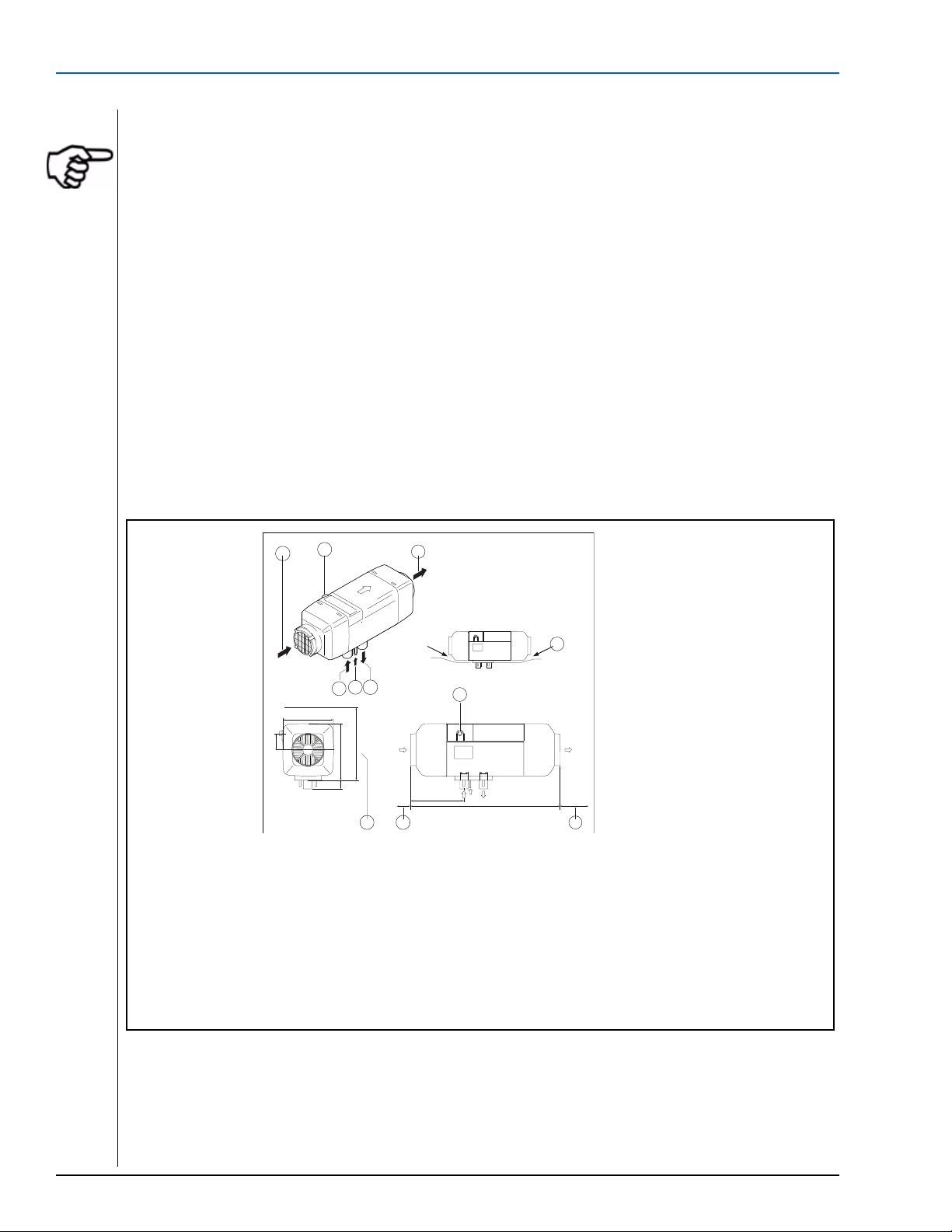
Installation Air Top 2000 ST - Air Top Evo 40/55
1. Cold air inlet
2. Cable outlet (optionally on right or left)
3. Hot air outlet
4. Exhaust gas outlet
5. Fuel inlet
6. Combustion air inlet
A. Space required for hot air outlet
B. Space requirements for cold air inlet
C. Space requirements for removing heater
D. Heater is supported only by the base
A
B
C
148
47,5
162
>200
25
>45
151
Ø25 Ø24
423
1
2
3
4
5
6
D
2
>80
4. Installation
IMPORTANT!
The regulations governing installation on pages 7-10 must be adhered to.
The heater must not be operated without the control unit cover (this will cause the heater to overheat)
The installation instruction manual supplied with the heater must always be observed.
4.1 Recommended Installation and Service Tools
• Digital Multi-Meter - Should be a good quality VAO meter.
• 1/2 Heavy-Duty, low speed drill with good quality, sharp drill bits and a selection of hole saws.
• Mounting/ Drilling Templates.
4.2 Installation Location
• In locker or control cabinet if they are well insulated. Install a contact barrier around the heating system so
that sails, fenders, bulkheads, etc. do not come into contact with hot parts!
• In the engine compartment of inboard diesel engines. Condition: Heating air intake from outside,
combustion air intake from outside or from engine compartment if this is well ventilated to the outside!
Figure 1. Dimensions of the Air Top EVO 40/55 Heater
Webasto Thermo & Comfort N.A., Inc. 12 www.techwebasto.com
Page 13
Air Top 2000 ST - Air Top Evo 40/55 Installation
6
311
> 20
120
6
Ø 22
Ø 22
130
120
121
>155
29
> 20> 20
Dimensions in millimeters
1
2
3
4
5
6
7
8
1. Hot air inlet
2. Hot air outlet
3. Combustion air inlet
4. Exhaust gas outlet
5. Fuel Intake
Figure 2. Dimensions of the Air Top 2000 ST Heater
4.3 To Install the Heater
The M6 nuts used to install the heater must be tightened with a torque of 6 Nm ±1 Nm (4.4 lb.-ft ± 74 lb.ft).
The installation dimensions and space requirement for service access are shown in the installation drawing
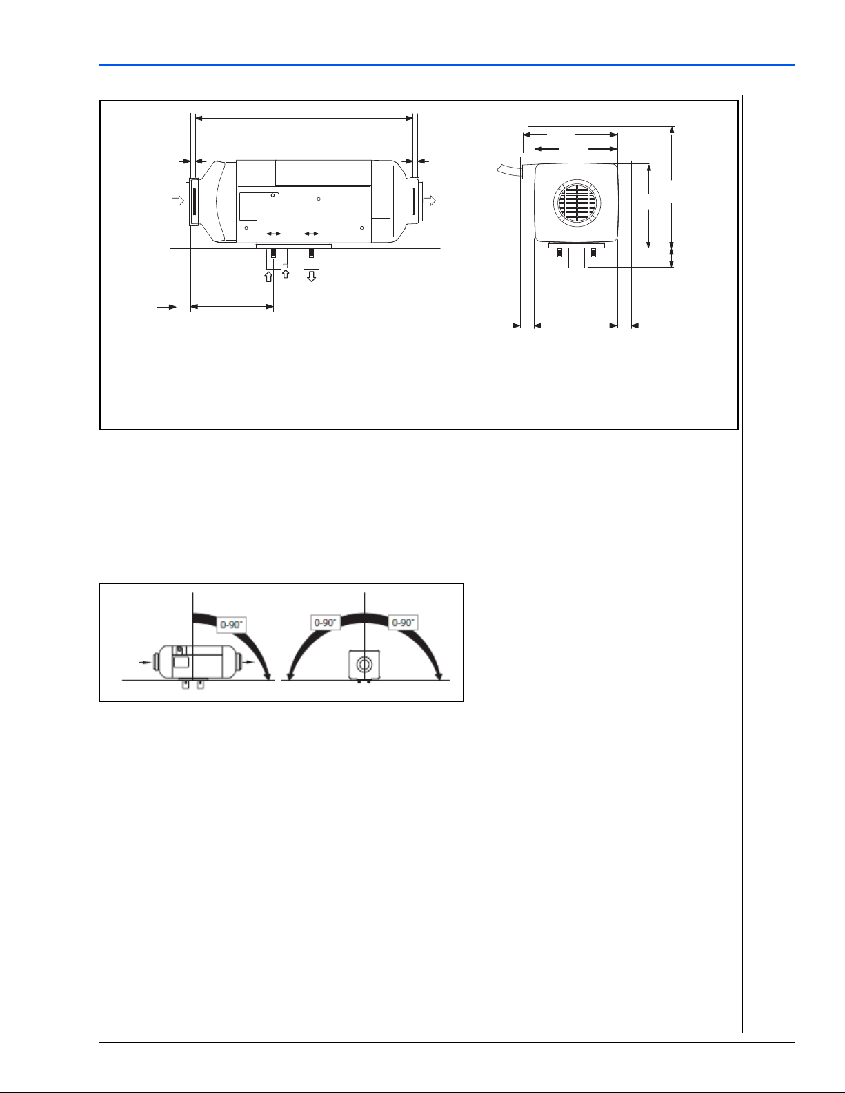
(Figure 1). The specified horizontal and axial angles must not be exceeded (Figure 3).
Figure 3. Recommended Installation Position for Heaters
6. Space required for hot air outlet
7. Space required for removing the heater
(service)
8. Cable outlet (either right or left)
Installation positions: observe possible inclination of ship!
• Recommended installation position: Exhaust outlet routed downward; heater unit parallel to ship's
longitudinal axis.
• Do not install transversely in sailboats!
Exception: if heater unit is primarily operated when boat is moored, or in motorboats then
installation transverse to longitudinal axis is also permissible.
www.webasto.us 13 Webasto Thermo & Comfort N.A., Inc.
Page 14
Installation Air Top 2000 ST - Air Top Evo 40/55
Ø 7.5
Ø 29 Ø 28
Ø 7.5
12
Ø 7.5
18
55
44
01020304050
Ø7.5
Ø7.5
Ø7.5
Ø26
Ø26
18
12
44
55
Figure 4. Install heater unit in longitudinal direction in sailboats!
A seal (Figure 6) must
time the heater is installed. The support area for the heater foot must be flat. A special tool can be
purchased from Webasto to drill the holes and, if necessary, smooth the support area. The seal can
compensate for unevenness of max. 1 mm
Warning!
The seal or foam gasket or both must be replaced each time the heater is removed and reinstalled.
be fitted between the heater and the vessel body. This seal must be replaced each
.
Figure 5. Rubber Seal Dimensions (Left: Air Top EVO 40/55) (Right: Air Top 2000 ST)
Figure 6. Rubber Seal (Left: Air Top EVO 40/55) (Right: Air Top 2000 ST)
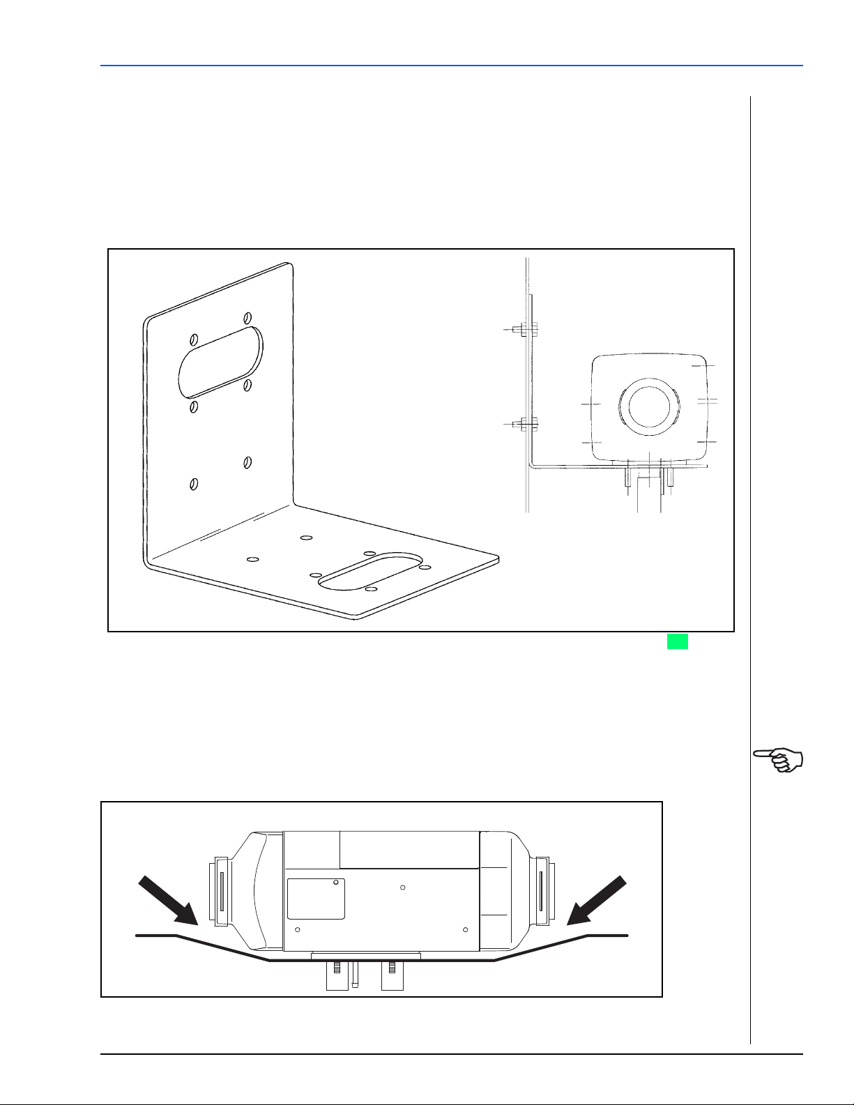
4.4 Universal Heater Mounting Bracket
WARNING!
Webasto Thermo & Comfort N.A., Inc. 14 www.techwebasto.com
Drowning risk! Be absolutely sure where you are drilling or punching holes! Inadvertently drilling large
holes through the hull of a vessel below the waterline can result in massive water intake in very short
order. Always be aware of your surroundings should you have to make an escape in an emergency.
Page 15
Air Top 2000 ST - Air Top Evo 40/55 Installation
Ensure that all moving part can move freely
For heater mounting, use the pre-drilled stainless steel mounting bracket, which is provided with the kit.
Make certain that the bracket is mounted securely to enable the heater to withstand “sea shock.” In some
cases it may be necessary to fiberglass a wooden pad in place at the mounting location to avoid drilling into
or through the hull of the vessel.
It is also preferable to position the bracket so that the heater exhaust outlet is vertical-down. This will provide
optimum heater operation and allow for vessel’s heel.
Figure 7. Universal Heater Mounting Bracket (Air Top EVO 40/55 and Air Top 2000 ST) ???
Place the heater on the mounting bracket. Ensure the rubber gasket on the base of the heater is in place.
Secure the heater using the provided hardware.
IMPORTANT!
After installation, check that the heater casing is not in contact with any parts of the vessel body.
A failure to do this may result in the hot air fan binding internally (Figure 8).
Figure 8. Installation
www.webasto.us 15 Webasto Thermo & Comfort N.A., Inc.
Page 16
Installation Air Top 2000 ST - Air Top Evo 40/55
Warning!
There is a danger of drowning when drilling into the ship's outer skin! Drilling below the water
line can cause the ship to sink! If the boat is in the water: check the drilling location! Have leak
sealing equipment available beforehand and familiarize yourself with possible escape routes!
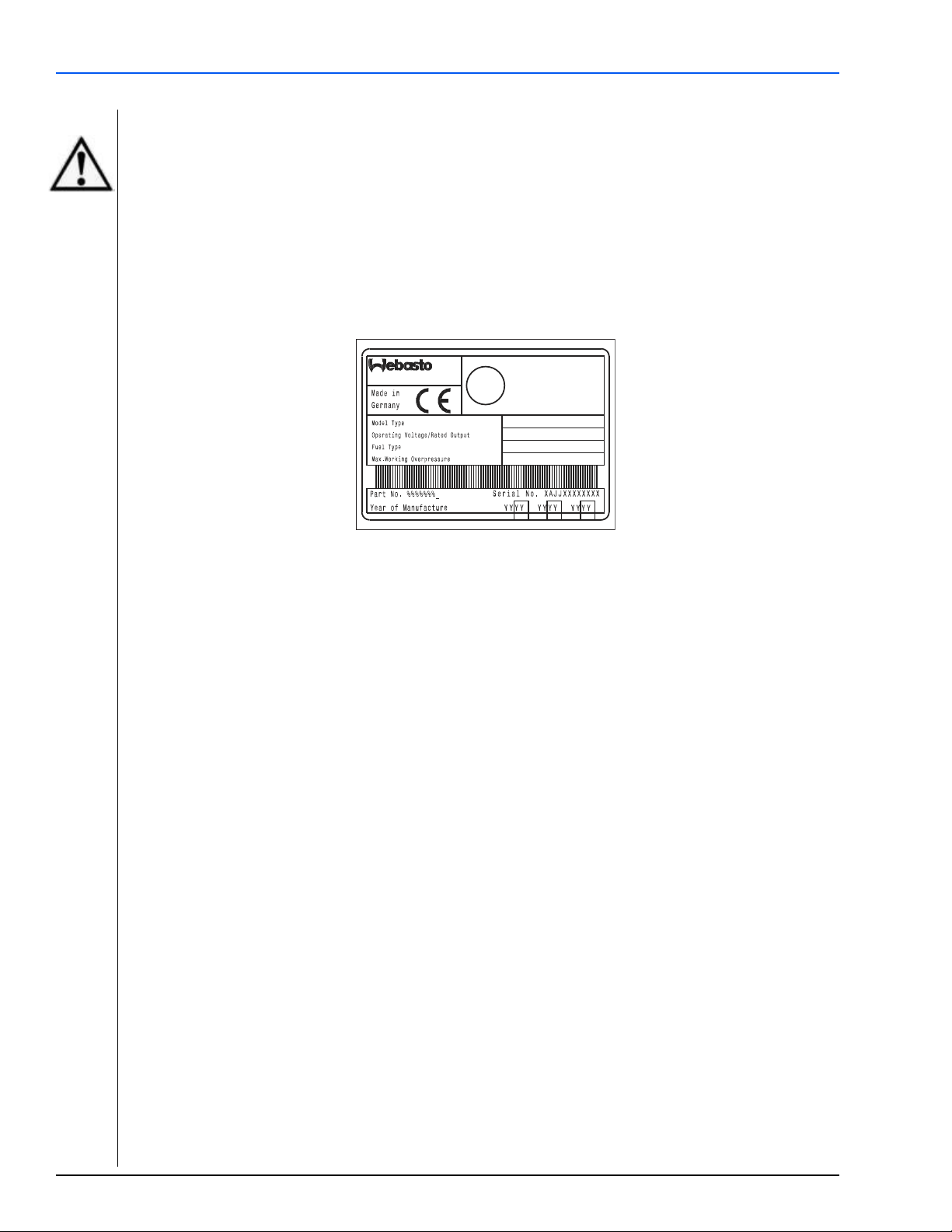
4.5 Factory Plate / Label
The model/serial number plate of the heater must be positioned so that it cannot be damaged and must be
clearly legible when the heater is installed (otherwise a duplicate model plate must be used).
Inapplicable years must be erased from the model plate.
Webasto Thermo & Comfort N.A., Inc. 16 www.techwebasto.com
Page 17

Air Top 2000 ST - Air Top Evo 40/55 Installation
5Air heater
6 Fuel Connection
7 Exhaust gas tube
8 Combustion air intake tube
9 Cool air inlet (return)
10 Heated air outlets
4.6 Installation Example
Figure 9. Installation example (installation conditions dependent on vessel type)
www.webasto.us 17 Webasto Thermo & Comfort N.A., Inc.
Page 18

Heating Air Circuit Air Top 2000 ST - Air Top Evo 40/55
5. Heating Air Circuit
5.1 General Information
WARNING!
Drowning risk! Be absolutely sure where you are drilling or punching holes for ducting! Inadvertently
drilling large holes through the hull of a vessel below the waterline can result in massive water intake in
very short order.
There are two types of heating air circuits of which both have certain advantages and disadvantages over
each other. The two common types are the fresh-air mode (extracting the heating air from the outside) and
the recirculating mode (extracting the heating air from the heated room).
In the case of the fresh-air mode, exhaust air discharge openings (fans, hatches) leading to the outside are
required in every room that is heated to prevent pressurization resulting in reduced flow through the heater.
The advantage of this operating mode is that fresh air is constantly introduced with a reduction in humidity,
as compared to the recirculating mode.
The recirculating mode of operation requires return air openings leading to the heating air intake ducting
socket of the heater so that the heating air can flow back to the heater to facilitate proper air circulation.
The advantage of this operating mode lies in the faster heating action through better heat utilization.
The total free cross-sectional area of the return air openings (or exhaust air openings of the rooms heated)
must be at least 1.5 times the size of the cross-sectional area of the heating air intake opening on the heater.
Irrespective of the position of the heating air inlet it must be ensured that no water can penetrate and that
the intake openings are not and cannot be obstructed by any objects stowed away.
Webasto air heaters feature powerful blowers that are capable of conveying the heating air through long
ducting runs for distribution throughout the vessel. Nevertheless, keep ducting runs and turns to a
minimum. Plan your heating circuit carefully to avoid high flow resistance. If flow resistance is too high, the
overheat protection will likely respond by switching the unit off.
Optional ducting system silencers are available to reduce any associated noise to a minimum.
The heating air circuit must be so designed that the heating air ducting can neither be crushed nor pinched.
Where heating air ducts need to be routed through bulkheads the use of pipe sockets is recommended so
that the ducts can be attached on both sides. Ducting hoses that are merely passed through the openings
without any protection will wear through with time.
When installing heating air ducting in a wet environment we recommend the use of spiral wire reinforced
ducting.
The use of closable air outlet nozzles is only allowed on branch lines (side rooms).
In air heating systems, manifolds with control flaps and cable control are frequently used. The air flow can
thus be distributed and adjusted by infinitely variable control.
Our accessories list contains all air circulation elements available (branches, elbows, etc.).
5.2 Heating Air Ducting Installation
Figure 10 illustrates the installation of an air heater in a sailboat with heating air intake from the cockpit.
Figure 11 illustrates the installation of an air heater with recirculating mode of operation in a sailboat.
Webasto Thermo & Comfort N.A., Inc. 18 www.techwebasto.com
Page 19

Air Top 2000 ST - Air Top Evo 40/55 Heating Air Circuit
Figure 10. Installation Diagram of an Air Heater with Fresh Air Mode of Operation
Figure 11. Installation Diagram of an Air Heater with Recirculating Mode of Operation
www.webasto.us 19 Webasto Thermo & Comfort N.A., Inc.
Page 20

Heating Air Circuit Air Top 2000 ST - Air Top Evo 40/55
5.3 Heating Air Intake Options
Option 1, Recirculation Mode:
The return air for heating is drawn in from the cabin (and any side-rooms) either via flexible ducting or return
openings. Use a Webasto fixed open grille to terminate the flexible duct. If the heater is mounted in a locker,
use the grille supplied in the kit to ventilate the locker.
Locate the air intake grille close to the heater intake, so that outside air is drawn in, in preference to the
locker air. It is not necessary to connect the grille to the heater with flexible ducting, unless there is a risk of
contaminated air reaching the heater.
If the heater is fitted in the engine room, use flexible ducting to draw in fresh cabin air, thus, avoiding engine
room air and associated fumes from being drawn into the heating air system.
Option 2, Fresh Air Intake Mode:
The air for heating is drawn into the heater from an external source either via flexible ducting or a grille
located on an external locker wall or wall opening. It is important that the rooms being heated are
adequately ventilated, otherwise air flow through the heater will be reduced, in which case the heater’s
overheat protection is likely to respond.
WARNING!
Asphyxiation risk! The fresh air intake must be located where exhaust fumes from the heater or the
engine cannot be drawn in to the heater intake and heating system.
To control the room temperature in the case of fresh air intake, an optional external temperature sensor
must be installed in a location with average room temperature and be connected to the control unit.
ATTENTION!
IT IS IMPORTANT THAT A SUPPLY OF CLEAN, UNOBSTRUCTED AIR REACHES THE HEATER THROUGHOUT ITS
OPERATION.
5.4 Hot Air Outlets
Hot air outlets should be located low in the rooms being heated. Be aware that the heated air discharged
can reach temperatures upwards to 90 °C (200 °F). Outlets should be located where contact with
passengers is unlikely. The hot air discharge should not be directed towards heat sensitive components or
surfaces in the immediate vicinity of the outlet.
Avoid long runs of ducting; they are inefficient and could lead to over heating. A heater is more efficient
when venting the hot air into free cabin space rather than being confined to a “rabbit warren” of ducting.
It is not always necessary to place outlets at every point where heat is desired. The pressure of the fan,
(particularly with minimal ducting), is effective at reaching most parts of the vessel. Keep the duct runs as
straight as possible and avoid running ducts where they could become crushed or broken.
The following diagrams illustrate typical ducting systems created with “Y” or “T” branches and outlets. Use
the clips provided to secure duct joints.
Webasto Thermo & Comfort N.A., Inc. 20 www.techwebasto.com
Page 21

Air Top 2000 ST - Air Top Evo 40/55 Heating Air Circuit
1
2 3 4 5 6
7
8
1 Air Inlet Nozzle - 60mm (2.36”) P/N 1322405
2 Ducting - 60mm (2.36”) . . . . . . P/N 50398497
3 Ducting - 60mm (2.36”) . . . . . . P/N 50398497
4 T-Junction - 60x60x60mm . . . . . P/N 1320472
2.36” x 2.36” x 2.36”
5 Ducting - 60mm (2.36”) . . . . . . P/N 50398497
6 Air Outlet Nozzle - 60mm (2.36”) . P/N 1322405
7 Ducting - 60mm (2.36”) . . . . . . P/N 50398497
8 Air Outlet Nozzle - 60mm (2.36”) . P/N 1322405
9
10
2 6
7
81 3 4
5
11
12
1 Open Air Inlet Nozzle . . . . . . . P/N 91569
90mm (3.54”)
2 Ducting . . . . . . . . . . . . . . . . . P/N 5000266
90mm x 1.5m (3.54” x 4.92’)
3 Ducting . . . . . . . . . . . . . . . . . P/N 5000266
90mm x 1.5m (3.54” x 4.92’”)
4 Y-Junction. . . . . . . . . . . . . . . . P/N 1320707
90x60x90mm (3.54” x 2.36” x 3.54”)
5 Ducting . . . . . . . . . . . . . . . . . P/N 5000753
90mm x 5m (3.54” x 16.4’)
6 Y-Junction . . . . . . . . . . . . . . . P/N 1320707
90x60x90mm (3.54” x 2.36” x 3.54”)
7 Ducting. . . . . . . . . . . . . . . . . . P/N 5000753
90mm x 5m (3.54” x 16.4’)
8 Open Outlet Nozzle. . . . . . . . . P/N 91569
90mm (3.54”)
9 Ducting. . . . . . . . . . . . . . . . . . P/N 5000316
60mm x 2m (2.36” x 6.56’)
10 Air Outlet Nozzle. . . . . . . . . . . P/N 1322405
60mm (2.36”)
11 Air Outlet Nozzle - . . . . . . . . . P/N 1322405
60mm (2.36”)
12 Ducting - . . . . . . . . . . . . . . . . P/N 5000316
60mm x 2m (2.36” x 6.56’)
Ducting Layouts - Typical
Figure 12. Air Top 2000ST - Typical 2 Outlet Ducting Layout
Figure 13. Air Top EVO 40 - Typical 3 Outlet Ducting Layout
www.webasto.us 21 Webasto Thermo & Comfort N.A., Inc.
Page 22

Heating Air Circuit Air Top 2000 ST - Air Top Evo 40/55
11
2 6 7 91 3 4 5
13
15
8
1214
10
1 Air Inlet Nozzle. . . . . . . . . . . . P/N 91569
90mm (3.54”)
2 Ducting . . . . . . . . . . . . . . . . . P/N 5000266
90mm x 1.5m (3.54” x 4.92’)
3 Y-Junction . . . . . . . . . . . . . . . P/N 1320707
90x60x90mm (3.54” x 2.36” x 3.54”)
4 Ducting . . . . . . . . . . . . . . . . . P/N 5000266
90mm x 1.5m (3.54” x 4.92’)
5 Y-Junction . . . . . . . . . . . . . . . P/N 1320707
90x60x90mm (3.54” x 2.36” x 3.54”)
6 Ducting . . . . . . . . . . . . . . . . . P/N 5000753
90mm x 5m (3.54” x 16.40’)
7 Y-Junction . . . . . . . . . . . . . . . P/N 1320707
90x60x90mm (3.54” x 2.36” x 3.54”)
8 Ducting . . . . . . . . . . . . . . . . . P/N 5000753
90mm x 5m (3.54” x 16.40’)
9 Air Outlet Nozzle . . . . . . . . . . P/N 91569
90mm (3.54”)
10 Ducting. . . . . . . . . . . . . . . . . . P/N 5000316
60mm x 2m (2.36” x 6.56’)
11 Air Outlet Nozzle . . . . . . . . . . P/N 1322405
60mm (2.36”)
12 Ducting. . . . . . . . . . . . . . . . . . P/N 5000316
60mm x 2m (2.36” x 6.56’)
13 Air Outlet Nozzle . . . . . . . . . . P/N 1322405
60mm (2.36”)
14 Air Outlet Nozzle . . . . . . . . . . P/N 1322405
60mm (2.36”)
15 Ducting. . . . . . . . . . . . . . . . . . P/N 5000316
60mm x 2m (2.36” x 6.56’)
Ducting Layouts - Continued
Figure 14. Air Top EVO 55 - Typical 4 Outlet Ducting Layout
Webasto Thermo & Comfort N.A., Inc. 22 www.techwebasto.com
Page 23

Air Top 2000 ST - Air Top Evo 40/55 Fuel System
6. Fuel System
This heater installation must follow the American Boat & Yacht Council, Inc. (ABYC) guidelines. The Fuel
system conforms to Inland Waterways specifications. Several specific regulations may apply including the use
of flame resistant fuel pipe such as copper pipe, and fire resistant fixings.
A sign must be affixed to the fuel tank’s filler neck warning that the heater must be switched off before
refueling. Affix the following sticker “Switch Off Heater Before Refueling” (included in scope of delivery) in
area of fuel filler neck.
6.1 General Information
This heater installation must follow the American Boat & Yacht Council, Inc. (ABYC) guidelines.
The Fuel system conforms to Inland Waterways specifications.
Several specific regulations may apply including the use of flame resistant fuel pipe such as copper pipe, and
fire resistant fixings.
The fuel must be extracted from the fuel tank of the vessel by means of a separate fuel pick-up (standpipe).
Do not “Tee” into engine fuel delivery or return lines.
Suitable fuel extraction devices or tank pick-up devices are contained in the accessory lists for the heaters, or
are included in the heater kit.
If an additional fuel tank needs to be installed for the fuel supply of the heater, we recommend this be
carried out by a marine installation center familiar with applicable marine industry directives, codes and
standards. Any safety hazards can thus be avoided.
6.2 Fuel Standpipe Installation
The fuel standpipe should be kept 25mm (1 in.) off the bottom of the fuel tank to prevent drawing sediment
and water into the heater’s fuel system.
www.webasto.us 23 Webasto Thermo & Comfort N.A., Inc.
Page 24

Fuel System Air Top 2000 ST - Air Top Evo 40/55
Legend for Figure 15:
11 Nut
12 Washer
13 Rubber gasket
14 Bushing (tank-boss)
15 Tank with 25mm (1 in.) hole
16 Tank with available N.P.T. threaded port
1
3
4
5
6
2
Figure 15. Fuel Standpipe
1. Cut fuel standpipe to length, approx. 25 mm (1 in.) off bottom of fuel tank. Angle the cut to prevent
clogging.
2. Remove burrs from cut end. Apply thread sealant to threaded fittings to prevent fuel leaks.
3. Install fuel standpipe using one of the following methods:
- use 1/4 or 1/2 spare port on top of fuel tank (if available) and install standpipe
OR
- drill or punch a 25 mm (1 in.) hole in a clear area on top of the fuel tank or fuel sender plate.
(Before drilling hole, apply grease to drill bit to catch metal chips)
- assemble tank-boss and fuel standpipe to form single unit.
- install standpipe by angling unit in so that one ear of the bushing hooks under the edge of the hole.
- repeat with the other ear in the same fashion.
4. Center in hole and clamp in place by tightening nut down until gasket begins to squeeze out slightly.
6.3 Auxiliary Fuel Tank
In the case of gasoline powered marine vessels, a separate fuel tank must be provided to supply Diesel fuel
to the Webasto air heater.
Gasoline
and must never be installed in marine vessels.
fuel fired Webasto auxiliary heaters are not recommended nor certified for marine use
6.4 Fuel Pump and Enclosure Installation
Appropriate mounting suggestions are contained in the following installation diagrams.
The maximum permissible fuel suction height and fuel supply height for the metering pump are referenced
in Figure 18 on the next page.
CAUTION!
The fuel pump must not be mounted lower than 500 mm (20 in.) below the top of the fuel tank.
The fuel pump assembly should be mounted as close to the fuel source as possible.
Webasto Thermo & Comfort N.A., Inc. 24 www.techwebasto.com
Page 25

Air Top 2000 ST - Air Top Evo 40/55 Fuel System
1 2
6
5
7
3
4
The total length of fuel line run including the fuel pick-up tube to the inlet of the fuel pump must not exceed
2 meters (78 in.) and a suction height no greater than 1 meter (39 in.).
On the outlet side of the pump, the fuel line must not exceed 6 meters (234 in.) and a delivery height no
greater than 3 meters (117 in.).
Ensure the fuel metering pump is mounted in a cool area. Ensure the correct direction of flow is observed.
Legend for Figure 16:
1 Fuel filter P/N 50487171
2 Fuel outlet connection
3 Fuel inlet connection
4 Pulse damper
5 Electrical cable
6 Fuel metering pump
7 P-clip
Figure 16. Fuel Pump and Enclosure Assembly
Observe Figure 17 closely.
The fuel pump outlet must be as shown (check-marked images) when installing the enclosure. This will
ensure the fuel metering pump is in the correct horizontal plane for proper operation and fuel metering.
Figure 17. Fuel Pump and Enclosure Installation
www.webasto.us 25 Webasto Thermo & Comfort N.A., Inc.
Page 26

Fuel System Air Top 2000 ST - Air Top Evo 40/55
Maximum suction height (A) = 1 m (39 in.)
Maximum suction length (A + B) = 2 m (78 in.)
Maximum delivery length (C + D) = 6 m (234 in.)
Maximum delivery height (D) = 3 m (117 in.)
Clamp
Bubble
Bubble
Wrong
Correct
Fuel System Parameters
Figure 18. Fuel System Limitations
Fuel Lines
Link the fuel supply from the standpipe to the fuel pump and from the fuel pump to the heater using the
metal fuel tubing and compression fittings supplied with the kit. Be sure to remove any burrs from the fuel
tubing using a small file after cutting. Place the nut and olive over the end of the tubing and re-assemble
onto the matting component.
The compression fittings should be tightened with moderate force only, as over-tightening will lead to a
distorted olive and leaking connections.
Route the fuel tubing as straight as possible, preferably running upwards towards the heater and securely
clip at frequent intervals, away from any heat source.
6.4.1 Connecting Two Fuel Lines with a Coupler Hose
Figure 19. Fuel line / coupler hose connection
Webasto Thermo & Comfort N.A., Inc. 26 www.techwebasto.com
Page 27

Air Top 2000 ST - Air Top Evo 40/55 Exhaust System
7. Exhaust System
7.1 General Information
Follow the diagrams below for correct installation guidelines and ensure the exhaust tube is routed with a
minimum of bends, not to exceed 270 degrees in total and with a minimum bend radius of 50mm (2 in.).
7.2 Through-hull Fitting
The exhaust gas through-hull fitting is preferably, to be mounted at the upper stern, if possible at least
500mm (20 in.) above the water line, and must not be immersed under water even when the boat is
heeling.
The hull side is acceptable for motorboats, but bear in mind the bow wave line and beam sea risk. In all
cases, the through-hull fitting must not point in the direction of travel, or be susceptible to high wind
pressure which may blow out the heater’s flame.
A suitable hole should be drilled at a 30 degree angle in the hull for the through-hull fitting.
Figure 20. Through-hull Fitting - Installation
7.3 Exhaust Tube Installation
Route the flexible exhaust in such a way that the heat cannot affect adjacent heat sensitive materials, plastic
piping, electric cables and sails etc. The stainless steel flexible exhaust tube supplied in the kit is wrapped in
a glass / silicon protective insulating sleeve (see Fig. 21, item 2).
If additional protection is required, we recommend over-sleeving with an additional layer of insulation
(available from your local Webasto marine dealer).
CAUTION!
DO NOT connect the heater exhaust into the engine or generator exhaust. Doing so will result in
unacceptable back-pressure levels and may damage the heater or cause operational failure.
DO NOT install a flapper valve (clamshell) over the exhaust outlet as this will cause excessive back pressure
within the exhaust system and heater.
DO NOT cover or block the exhaust outlet while the heater is in operation.
The end of the exhaust gas line must be routed with a goose-neck bend and be pitched downward toward
the outlet (see Fig. 21, item 1). Any splash water that may have penetrated can thus drain back out again
and not into the heater.
The exhaust gas line is to be kept as short as possible. The maximum length of 5 meters (16.5 feet) without
muffler or 2 meters (6.5 feet) with muffler must on no account be exceeded. The total radius of bends
should not exceed 270 degrees with a minimum bend radius of 50mm (2 in.).
www.webasto.us 27 Webasto Thermo & Comfort N.A., Inc.
Page 28

Exhaust System Air Top 2000 ST - Air Top Evo 40/55
The exhaust tube and exhaust components must be securely fastened using approved exhaust tube clamps
and P-clips as supplied with the heater kit. Under no circumstances should coolant hose style clamps be used
to secure exhaust tubing to the heater or other exhaust components.
If exhaust gas lines are routed through rooms occupied by persons, these pipes must be replaced with
genuine Webasto replacement parts after at least 10 years of service.
At the lowermost point of the exhaust gas line, a condensation water drain (see Fig. 21, item 3) can be
installed via which the condensation water collecting in the exhaust gas line can be drained off at regular
intervals. A condensation drain is provided in the heater kit to drain off any collected condensation or sea
water that may enter the exhaust. Fill condensation drain with water to provide a seal against exhaust gas
leakage once drain has been installed.
WARNING!
Avoid asphyxiation! If the exhaust gas tube is routed through the inside of the vessel, exhaust gas tube
must be as leakproof as possible:
- use only Webasto approved exhaust clamps and firmly tighten clamps.
- an approved exhaust sealant can be used on the inside of the exhaust tube at all connection points
- use condensation water drain
- if desired, use an optional gas tight exhaust muffler to reduce interior noise (see accessories)
Figure 21. Exhaust System
Legend for Figure 21:
1. Goose-neck (prevents water intrusion)
2. Heat insulating sleeve
3. Condensation drain-off
7.4 Combustion Air Intake Tube Installation
WARNING!
Asphyxiation risk! The combustion air required for the heater may only be drawn in from the outside or
from spaces that are not occupied by persons e.g. ventilated foredeck box or ventilated *engine
compartment (Diesel only).
*Explosion risk! Do not draw combustion air from engine compartment of gasoline
Webasto Thermo & Comfort N.A., Inc. 28 www.techwebasto.com
powered vessels.
Page 29

Air Top 2000 ST - Air Top Evo 40/55 Exhaust System
5mm (3/16”)
1
2
Keep combustion air intake
tube opening clear of
obstructions!
The maximum length of the combustion air intake tube is 5 meters (16.5 feet) without a silencer or 2 meters
(6.5 feet) with a silencer. On no account are these lengths to be exceeded. The total radius of bends should
not exceed 270 degrees with a minimum bend radius of 50mm (2 in.).
Where combustion air is drawn from an internal source, the combustion air tube should be routed away
from the heater with a downward pitch to prevent condensation or moisture from collecting in the tube.
Where combustion air is drawn from an external source, the end of the combustion air intake tube must be
routed with a goose-neck bend (see Fig. 22, item 1) with a downward pitch toward the outlet so that any
water that may penetrate can drain out and not into the heater. A 5mm (3/16 in.) condensation weep hole
must be provided at the lowest point between the goose-neck and the heater to allow drainage of any
trapped condensation or splash water (see Fig. 22, item 2).
Figure 22. Drain Hole - External Combustion Air Intake
To avoid pressure differences between exhaust gas outlet and combustion air inlet, the openings of the
through-hull fittings should be located in an area where equal pressure prevails.
Do not point the inlet of the combustion air tube in the direction of travel when intake air is drawn from an
external source.
Secure intake tube to heater with hose clamp provided. Ensure the fuel pump connector harness is in place
in the slot provided in the air intake port before tightening clamp. Secure the tube to adjacent structures
with P-clips or nylon wire ties.
www.webasto.us 29 Webasto Thermo & Comfort N.A., Inc.
Page 30

Electrical Connections Air Top 2000 ST - Air Top Evo 40/55
Extension Harness
Air Top 2000 ST shown
8. Electrical Connections
8.1 General Information
Electrical connections are to be carried out in accordance with the circuit diagrams contained in this
installation manual.
2
Main power leads must have a minimum cross-sectional area of 4.0 mm
should be routed a short as possible. In the case of lead lengths greater than 7.5 m (24.5 ft.), the
existing cables with 4.0 mm
IMPORTANT! All power connections must be fused within 14” of the battery.
When installing the electrical system make sure that the components are installed in protected, dry areas to
prevent corrosion. When leads need to be extended, make sure you use cables with the correct crosssectional area!
We recommend a second battery to be installed for the operation of the heater which should, if possible,
not be used for engine starting purposes. To avoid having to charge the battery too often its capacity should
not be too small.
If you have highly sensitive electronic components on board, a special electrical interference suppression may
become necessary. In this case, please consult a competent specialist workshop.
2
wires must be replaced with 6.0 mm2 (AWG 8 Gauge) wires.
(AWG 10 Gauge) and
When actuating the battery disconnect switch (if equipped), wait until the after-running period of the heater
has been completed.
Harness Connection
Figure 23. Control and Fuel Pump Electrical Harnesses - Air Top Heater Standard Connection
For shipping purposes, the fuel pump harness may be tucked in the air intake port on the bottom of the
heater. Carefully remove bundled harness from intake port, route it to the desired fuel pump location and
install the two terminals into the supplied connector. The fuel pump wires can be installed in either location
in the connector. There is not a specific wire location.
A fuel pump extension harness may also be used. Connect extension harness directly between original
harness and fuel pump. Refer to Figure 23.
The heater power / control harness can be routed out of the right or left hand side of the heater subject to
individual requirements.
Webasto Thermo & Comfort N.A., Inc. 30 www.techwebasto.com
Page 31

Air Top 2000 ST - Air Top Evo 40/55 Electrical Connections
ATTENTION:
Be sure not to touch the printed circuit board or conductors. Care should be taken to prevent discharge of
static electricity that can damage sensitive circuitry.
All the cables and wires that are not required must be insulated against accidental shorting or grounding.
NOTE:
The electrical connection is made as shown in the system circuit diagram.
8.2 Heater Connection
After it is switched off the heater continues running. The voltage supply must not be disconnected before
approx. 240 seconds have elapsed. An electrical battery disconnect or relay can be connected in accordance
with the wiring diagram.
Figure 24. To remove the control unit cover
AT EVO 40/55
Figure 25. Connector Diagrams
NOTE:
- Raise the control unit cover on both sides using a blunt blade (Figure 24 arrows).
- Plug in wiring harness connector at control unit.
- Route cable through left or right cable lead-through.
- Position cable grommet such that the cable lead-through is sealed off in the control unit cover.
- Connect the supply voltage to the vessel electrical system.
- Install fuse holder in vessel interior.
- Connect heater corresponding to the above connector diagram.
- Replace control unit cover.
www.webasto.us 31 Webasto Thermo & Comfort N.A., Inc.
Page 32

Electrical Connections Air Top 2000 ST - Air Top Evo 40/55
F = 20A (12V)
F = 15A (24V)
Figure 26. Fuse holder - weather sealed
Shaft requires a 12 mm (15/32 in.)
hole to mount.
8.3 Supply Voltage Connection
To provide the heater with adequate protection, an additional
flat fuse holder is to be installed (supplied with the heater).
Ideally from the vessel’s central electrical system or at the
batteries.
A weather sealed fuse holder is to be fitted to protect the
heater (supplied with the heater harness).
8.3.1 Fuse Specifications
Air Top EVO 40/55: F = 20 A (12v); F = 15A (24V)
Air Top 2000 ST: F = 15 A (12v); F = 10A (24V)
IMPORTANT!
All power connections must be fused within 14” of the
battery.
IMPORTANT!
The Air Top EVO 40/55 requires 6.25 amps @ 12 volts or 12.5 amps @ 24 volts during start-up. The
main power connection has to be made at a circuit designed to sustain this load without voltage
drop. Cigar lighter sockets and auxiliary power outputs for C.B. radio’s and other electronic
accessories are not considered adequate power supplies for the Air Top EVO 40/55.
The fuse holder may only be installed in an interior space protected from splash water or damage. Mount
the fuse holder in an upright position, see Figure 27 for installation position variance. Secure the fuse holder
mounting plate to a flat surface and clip the fuse holder into the mounting plate.
Figure 27. Fuse Holder, Installation Position
8.4 Control Element (Rheostat)
Figure 28. Control Element (rheostat)
The wiring harness is prepared for connection to
the control element.
Simply pull on the connector housing to unplug the
connector.
The connector housing can be locked (self-locking
action) by simply pulling on the wiring harness.
Locate the control element in a convenient
location.
The control element is not affected by
temperature.
Temperature is monitored inside the heater or via
an optional external temperature sensor (see Figure
31).
Webasto Thermo & Comfort N.A., Inc. 32 www.techwebasto.com
Page 33

Air Top 2000 ST - Air Top Evo 40/55 Electrical Connections
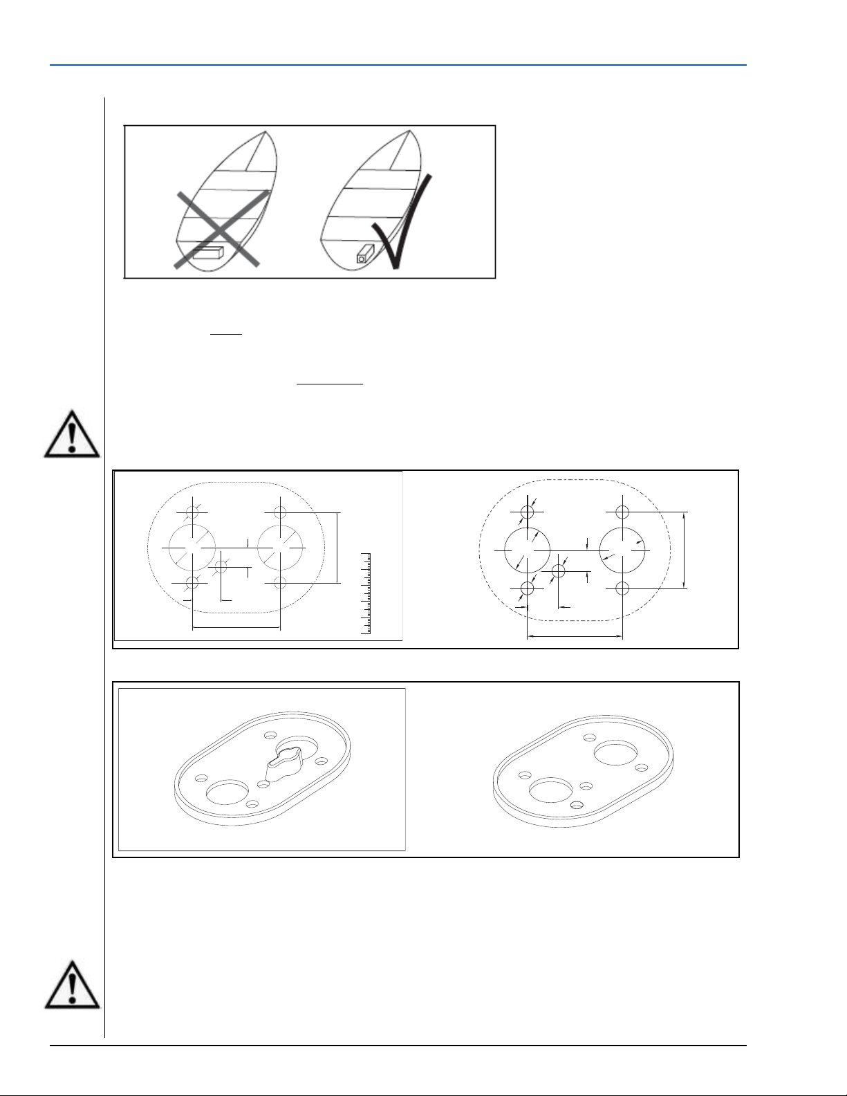
Figure 29. Installation of the control element - correct
Figure 30. Installation of the control element - incorrect
External temperature sensor
Cover
Figure 31. External temperature sensor - optional
NOTE:
The fibre optic lens must be in contact with
the rotary knob.
NOTE:
The rotary knob must sit flush with the
bezel (Figure 29) not above it as illustrated
in Figure 30.
NOTE:
As an option an external temperature
sensor may be installed in the passenger
cabin.
See installation instructions included with
the sensor or see the service instructions in
the Workshop manual for further
information.
www.webasto.us 33 Webasto Thermo & Comfort N.A., Inc.
Page 34

Electrical Connections Air Top 2000 ST - Air Top Evo 40/55
Figure 32. Control element (SmarTemp)
Figure 33. SmarTemp drilling dimensions
8.5 Control Element (SmarTemp)
The Control Panel should be installed in a suitable location on a flat surface if possible in a visible area.
– Connect control panel to existing
connectors on heater-unit wiring harness
(see “Connections Diagrams Section”)
– Use the drilling dimensions (fig. 33) to
lightly mark the two mounting holes.
– To route wire harness through the
mounting surface, drill a 22 mm hole.
Make sure to push harness through the
hole before installing terminals into
connector housing)
– Secure the SmarTemp Control using the
two supplied #4 screws.
– Follow the electrical pin-out fig. 34 to
install the supplied harness connector and
harness adapters.
– Apply any warning or caution stickers that
are supplied with the SmarTemp Control.
– Observe the installation / operating manual
supplied for proper menu setup.
NOTES:
– Always make sure there are no obstacles behind
the mounting location prior to drilling.
– Ensure good readability when selecting installation
location.
– Observe information on adhesive labels and
colored markings when connecting the control
element to vessels wiring harness.
Webasto Thermo & Comfort N.A., Inc. 34 www.techwebasto.com
Page 35

Air Top 2000 ST - Air Top Evo 40/55 Electrical Connections
"
Figure 35. Installing control element MC04
98
R2
63
Figure 34. Air Top 40/55 EVO with SmarTemp Control - connection diagram
8.6 Control Element (MC04)
The Control Panel should be installed in a suitable location (on a flat surface if possible) in a visible area.
– Use Drilling Template for Control Panel MC04 for cut-out and holes (see “drilling templates”)
– Connect Control Panel to existing connectors on heater-unit wiring harness (see “Connection diagram/
Circuit diagram”)
– Pre-mount control unit in cut-out
– Lightly press fastening screws into holes and screw in
– Carefully clip on trim frame
NOTES:
–Control Panel is only intended for
installation in passenger compartment
–Ensure good readability when selecting
installation location
–Observe information on adhesive labels
and colored markings when connecting
Control Panel to vessel wiring harness
www.webasto.us 35 Webasto Thermo & Comfort N.A., Inc.
Figure 36. MCO4 Drilling Dimensions
Page 36

Electrical Connections Air Top 2000 ST - Air Top Evo 40/55
Figure 37. Connection diagram for Air Top EVO 40/55 with control element MC04
Webasto Thermo & Comfort N.A., Inc. 36 www.techwebasto.com
Page 37

Air Top 2000 ST - Air Top Evo 40/55 Pre-Start Checklist
9. Pre-Start Checklist
This checklist is provided as a technical aid to technicians for final heater installation guidance.
HEATER MOUNTING
1 Is the heater installation safely secure / rigid?
(Ensure that all bracket bolts are tight)
2 Is there a safe clearance from heat generating
Components? (I.e. exhaust, etc...)
3 Is the heater mounted in an acceptable position
according to the limitations noted in the
installation manual?
4 Is the heater installed in a protected location?
ELETRICAL
1
Has all wiring been safely secured away from moving components
and / or heat sources?
2
Check for proper power and ground connections.
3
Check for proper fuse connection.
4
Verify the correct fuses are in the specified locations per the installation
manual.
Ensure heater and vessel fuse boxes are closed and secure. Was the
5
Webasto fuse block installed in a location protected from water and / or
moisture?
6
Ensure battery is mounted securely and connections are properly
tightened.
7
Ensure battery is at ? 12.2Vdc.
Complete
(Yes/No/Comments)
Complete
(Yes/No/Comments)
FUEL SYSTEM
1 Is the standpipe properly mounted in the fuel tank?
(sealed, structural integrity maintained).
2 Validate the standpipe does not interfere with function of sending unit by
checking fuel gauge for proper operation before completing installation
of tank.
3 Verify that all fuel lines are properly secured and are a safe distance (min.
4 in.) from exhaust systems and / or moving components.
4 Check all fuel lines for leaks or kinks.
5 Check fuel line clamps for proper positioning and tightness. Ensure fuel
system is free of leaks.
6 Ensure fuel pump is securely mounted in a cool location
NOTE: Vessel fuel tank area is generally a location with minimal sound
transfer path to vessel interior.
www.webasto.us 37 Webasto Thermo & Comfort N.A., Inc.
Complete
(Yes/No/Comments)
Page 38

Pre-Start Checklist Air Top 2000 ST - Air Top Evo 40/55
EXHAUST SYSTEMS Complete
(Yes/No/Comments)
1 Is the muffler and clamps securely tightened?
2 Has muffler and exhaust tube been routed a safe distance (min. 4 in.)
from flammable material?
3 Ensure condensation drain-off is at the lowest area of exhaust tube.
4 Ensure exhaust is venting a safe distance from any vessel interior
openings.
5 Ensure exhaust is venting in the direction that will not cause back
pressure while in motion.
COMBUSTION AIR INTAKE Complete
(Yes/No/Comments)
1 Is the combustion air intake drawing fresh air from a non-turbulent
location? (i.e. not in direction of travel)
2 Ensure air intake system is securely fastened.
HEATER FUNCTION Complete (Yes/No/
Comments)
1 Ensure heater starts and runs for a minimum of 20 minutes.
2 Ensure timer (control device) is functions properly.
COSMETICS Complete (Yes/No/
Comments)
1 Has the vessel interior, engine compartment, and storage compartment
been inspected for cleanliness after installation.
2 Has user manual been placed in vessel?
If you have any questions, contact our technical support team at (800) 860-7866 or via email at:
info-us@webasto.com
.
Webasto Thermo & Comfort N.A., Inc. 38 www.techwebasto.com
Page 39

Air Top 2000 ST - Air Top Evo 40/55 Starting Heater for the First Time
Control Element
Changes to the settings
on the control element
are implemented after
a delay.
!
Rotary knob for:
- Switching on and off
- Setting the room temperature
Resetting after a fault cut-out
-
Indicator / Error code display
10. Starting Heater for the First Time
- Make sure the control unit cover is fitted in position.
- Install contact guard if necessary.
- Bleed the fuel supply system carefully using Webasto Thermo Test PC Diagnosis.
- Switch on the heater via the control element (see control element operating instructions).
NOTE:
As a result of the low fuel consumption the heater must be switched on several times to fill the fuel line and
prime the system.
Conduct a trial of the heater to check all the connections for leaks and to ensure that they are secure. If the
heater suffers a fault during operation, the fault must be located and remedied.
10.1 Control Element Description
10.1.1 Rheostat
Figure 38. Control element (Rheostat)
10.1.2 SmarTemp Control
Figure 39. Control element (SmarTemp Control)
www.webasto.us 39 Webasto Thermo & Comfort N.A., Inc.
Page 40

Starting Heater for the First Time Air Top 2000 ST - Air Top Evo 40/55
10.1.3 MC-04
Figure 40. Control element (MC-04)
10.2 Product Registration
- Register the product on the internet under: http://techwebasto.com
- Hand over the registration document to the next owner or user of the unit.
Webasto Thermo & Comfort N.A., Inc. 40 www.techwebasto.com
Page 41

Air Top 2000 ST - Air Top Evo 40/55 Troubleshooting
11. Troubleshooting
11.1 Error code output
- If an error occurs, the unit outputs a fault code via the control element.
- You will find further information in the operating instructions and in the heater workshop manual.
NOTE:
An error code is generated on the control element indicator light after an error has occurred. When
determining the generated code, there will be a series of 5 fast flashes after which, the error code will be
generated by a sequence of long flash pulses, count only the long flash pulses to obtain the code. Error
codes are shown in the table below.
If the heater is fitted with a combination timer, an error message will appear on the display of the timer after
a fault occurs. If the control element is used, the error number is indicated by the indicator light flashing:
Air Top EVO 40/55 Fault Codes
F 00 Control unit error / incorrect parameter set / warm start recognition
F 01 No start (after 2 attempts to start) / no flame formation
F 02 Flame failure (repeated more than 3 times)
F 03 Under voltage or over voltage
F 04 Premature flame recognition
F 06 Temperature sensor interrupt or short circuit
F 07 Metering pump interrupt or pump short circuit
F 08 Fan motor interrupt or short circuit or overload or blocked
F 09 Ceramic glow pin interrupt or short circuit
F 10 Overheating: Resulting in permanent heater fault lock-out
F 11 Overheating sensor interrupt or short circuit
F 12 Heater lock-out
F 13 Heater lock-out permanent
F 14 Overheating sensor incorrect position
F 15 Set point generator interrupt
Air Top 2000 ST Fault Codes
F 00 Control unit error / incorrect data set / customer bus defective
F 01 No start (after 2 attempts to start) / no flame formation
F 02 Flame failure (repeated more than 3 times)
F 03 Under voltage or over voltage
F 04 Premature flame recognition
F 05 Flame monitor (gasoline heater) interrupt or short circuit
F 06 Temperature sensor interrupt or short circuit
F 07 Metering pump interrupt or pump short circuit
F 08 Fan motor interrupt or short circuit or overload or blocked
F 09 Ceramic glow pin interrupt or short circuit
F 10 Overheating: Resulting in permanent heater fault lock-out
F 11 Overheating sensor interrupt or short circuit
F 12 Heater lock-out
F 14 Overheating sensor incorrect position
F 15 Set point generator interrupt
11.2 Fault Lock-out
The control unit continuously monitors the heater operation. The control unit identifies errors on individual
heater components and faults during operation. Should the control unit experience component errors and
operational faults, the heater will be shut down.
www.webasto.us 41 Webasto Thermo & Comfort N.A., Inc.
Page 42

Troubleshooting Air Top 2000 ST - Air Top Evo 40/55
The heater is shut down (fault lock-out) if:
– No or incorrect start
– Temperature sensor defective
– Overheating sensor interrupt or short circuit
– Overheating sensor installed incorrectly
– Ceramic glow pin interrupt or short circuit
– Fan motor overload or blocked or short circuit or interrupt
– Error in the fuel metering pump or overheating guard circuit (start phase only)
– Under voltage less than 10 V or over voltage greater than 15 V and for longer than 20 seconds (on 12 V
heater)
– Under voltage less than 20 V or over voltage greater than 32 V and for longer than 20 seconds (on 24 V
heater)
– Control unit defective
–Overheating
The fuel supply is stopped if the heater overheats.
The heater continues to run in the same way as if it is switched off manually.
After the heater stops the control unit will be set to fault lock-out.
Overheating is indicated by the indicator flashing 10 times.
Rectify the cause of the fault.
To reset the fault, switch the heater on and off briefly (at least 2 seconds).
If serious faults, such as overheating or no start, occur frequently, the heater will be set to fault lock-out (F
12) and can be restarted by disconnecting the supply voltage (e.g. removing the fuse).
Webasto Thermo & Comfort N.A., Inc. 42 www.techwebasto.com
Page 43

Air Top 2000 ST - Air Top Evo 40/55 Technical Data
12. Technical Data
12.1 Heater
Heater Air Top 40 D Air Top Evo 55 D Air Top 2000ST
Type approval: EMC
Type approval: Heating
Design
E1 03 5529 E1 03 5529
E1 00 0385 E1 00 0386 e1*2001/56*0022*00
Air heater with
vaporising burner
Air heater with
vaporising burner
e1*72/245*95/
54*1085*00
Air heater with
evaporator burner
Heat flow over control range [kW]
Fuel
Fuel consumption over control range
Rated voltage [V]
Operating voltage range [V]
Rated power consumption over control range [W]
Permissible ambient temperature (operation/storage):
Heater [°C]
Permissible ambient temperature (operation/storage):
Fuel pump [°C]
Permissible combustion air intake temperature [°C]
Set-point temperature range [°C]
Volumetric flow rate with pressure loss in cold/hot air
system 0.5 hPa [m
3
/h]
CO2 in exhaust gas: Rated heating capacity VL [kW]
CO2 in exhaust gas: CO2 rated value VL [vol%]
CO2 in the exhaust fumes (normal function range) 1kW
CO2 in the exhaust fumes (normal function range) 2kW
Heater length [mm]
Heater width [mm]
Heater height [mm]
Heater weight [kg]
IP class: Heater
IP class: Fuel pump
Max. length of combustion air line and exhaust line
with exhaust silencer [m]
Max. length of combustion air line and exhaust line
without exhaust silencer [m]
1.5 to 3.5 (4.0) 1.5 to 5.0 (5.5) 0.9 - 2.0
Diesel / bio-diesel DIN
EN 590/ DIN EN 14214
0.15 - 0.36 (0.41) kg/h
0.18 - 0.43 (0.49) l/h
12 / 24 12 / 24 12 / 24
10.5 to 16 / 20.5 to 31 10.5 to 16 / 20.5 to 31 10.5 - 16 /21 - 32
15 to 40 (55) 15 to 95 (130) 14 to 29
–40 to +40 /
–40 to +85
–40 to +20 /
–40 to +85
–40 to +20 –40 to +20 –40 to +20
+5 to +35 +5 to +35 +5 to +35
Max. 132 (140)
3.5 5.0 N/A
9.2
N/A N/A 5.0 ... 8.0
N/A N/A 9.0 ... 12.5
423 ± 2 423 ± 2 311 ± 2
148 ± 1 148 ± 1 120 ± 1
162 ± 1 162 ± 1 121 ± 1
5.9 5.9 2.6
IP5K4K IP5K4K
IPX6 / IPX7 / IP6K9K IPX6 / IPX7 / IP6K9K
2 2
5 5
Diesel / bio-diesel DIN
EN 590/ DIN EN 14214
0.15 - 0.51 (0.56) kg/h
0.18 - 0.61 (0.67) l/h
–40 to +40 /
–40 to +85
–40 to +20 /
–40 to +85
Max. 200 (220) Max. 93
10.0
0.1 - 0.21 kg/h
(0.12 - 0.24 l/h)
–40 to +40 /
–40 to +20 /
Diesel/PME
–40 to +85
–40 to +85
N/A
Max. permissible pressure loss in cold and hot air system [hPa]
2.0 3.0
Figure 41. Technical Data Table
www.webasto.us 43 Webasto Thermo & Comfort N.A., Inc.
Page 44

Technical Data Air Top 2000 ST - Air Top Evo 40/55
The technical data apply under the following conditions:
- Ambient temperature: +20
- Geodetic height: 0 m above sea level
- Rated voltage
The standard tolerances of ±10 % for heaters shall apply if no limits are specified
The values in brackets apply for the extended heating capacity (boost function) that is activated temporarily
during each start.
12.2 Electrical Components:
Control unit, motor, metering pump, lamp in the timer and ceramic glow pin / flame monitor are designed
for either 12 or 24 Volt.
12.3 Fuel for Air Top Heaters (Diesel/Heating Oil):
The diesel fuel specified by the vessel manufacturer must be used. Heating oil may also be used as long as it
complies to the normal quality available on the North American market.
°C
.
We know of no negative influences due to additives.
If fuel is extracted from the vessel’s tank, follow the additive instructions issued by the vessel manufacturer.
If you change to low-temperature fuel, the heater must be operated for approx. 20 minutes so that the fuel
system is filled with the new fuel.
The Air Top EVO 40/55 heater is also licensed for use with PME (bio-diesel), which complies with DIN EN
14214.
Webasto Thermo & Comfort N.A., Inc. 44 www.techwebasto.com
Page 45

Air Top 2000 ST - Air Top Evo 40/55 Wiring Diagrams
13. Wiring Diagrams
13.1 Legend to Air Top EVO 40/55 Wiring Diagrams
Item Description Remarks
A1 Heater Air Top EVO 40 / 55
A2 Control unit
A3 UniBox –
B2 Room temperature sensor Inside
B3 Overheat temperature sensor Overheating protection
B4 Room temperature sensor Outside
B5 Exhaust gas temperature sensor Overheating protection / flame monitor
E Glow plug –
F1 Fuse 24 V, 15 A / 12 V, 20 A Blade type fuse SAE J 1284
F2 Fuse 4 A Not included in wiring harness
F3 Fuse 1 A Blade type fuse SAE J 1284
F4 Fuse 4 A Not included in wiring harness
F5 Fuse Value [in A] to be selected corresponding to wire cross section
H1 LED green (in Item S1) Operating indicator
H2 LED red (in Item P) Lighting: Quick Heating button, Ready indicator, ON indicator
H3
H4 Bulb/LED (in Item P and S) Display and button lighting
H7 Symbol on display –
M1 Motor Combustion air and heating air blower
P1 SmartControl –
P2 SmartControl / Multi Control –
S Air Top Evo Multi Control (MC04) ON/OFF button, selector switch for additional functions and temperature selector
S1 Rotary selector control element ON switch and temperature selector
S2 Switch Ventilation
S3 Switch CO2 setting
X1 – X6 Plug connection To Item A2
X7 Plug connection To control unit
X8 Plug connection To Item A2
X9 Plug connection –
X9 (a) Plug connection To Item S or S1
X9 (b) Plug connection To Item S or S2
X9 (c) Plug connection W-bus, optional Telestart (12 V) or Thermo Call connection
X1 – X11 Plug connections In heater on control unit
X13 Plug connection To Item Y1
X14 Plug connection –
X15 Plug connection To Item S3
X16 Plug connection Wiring harness connection DP42
X17 Plug connection Wiring harness connection DP42
Y1 Fuel pump DP42
Heating symbol on display
(in Item P)
Control unit 1580
Control unit 1574
Operating indicator
www.webasto.us 45 Webasto Thermo & Comfort N.A., Inc.
Page 46

Wiring Diagrams Air Top 2000 ST - Air Top Evo 40/55
Legend to remarks in Air Top EVO 40/55 wiring diagrams
Item Remarks
Positive from terminal 15/75 to connection 10: Continuous heating mode is possible in connection with quick
1
heating function provided the ignition is switched on.
2 All heater versions: W-bus diagnosis connection
3 CO2 setting (see workshop manual)
4 Connection to terminal 30: Continuous heating mode is possible with ignition switched off.
External temperature sensor (optional)
5
Installation as system: External temperature sensor must be connected to master heater.
Pin 7 "Boost"
6
Only ambulance heater version (door contact connected to terminal 31).
7 Wiring harness adapter (optional)
8 Switching capacity 250 mA
Connector X7 pin assignments (Air Top EVO 40/55)
Item Remarks
1 Battery disconnect / operation indicator
2 Power supply, control element / error code output
3 Battery disconnect / operation indicator
4 Voltage supply + (terminal 30)
5 Voltage supply - (terminal 31)
6 Switch-on signal (ON/OFF)
7 Multifunction (ventilation, boost, ECO) with control element MC02, only Boost activation for ambulance units
8 Set-point sensor –
9 CO2 setting
10 Not used
11 Set-point sensor +
12 W-bus (Webasto Thermo Test PC-Diagnosis connection)
Webasto Thermo & Comfort N.A., Inc. 46 www.techwebasto.com
Page 47

Air Top 2000 ST - Air Top Evo 40/55 Wiring Diagrams
13.2 Wiring Diagrams for Air Top EVO 40/55
Figure 42. Air Top 40/55, 12V / 24V with rheostat
www.webasto.us 47 Webasto Thermo & Comfort N.A., Inc.
Page 48

Wiring Diagrams Air Top 2000 ST - Air Top Evo 40/55
Figure 43. Air Top 40/55, 12V/24V with MultiControl (MC04) control element
Webasto Thermo & Comfort N.A., Inc. 48 www.techwebasto.com
Page 49

Air Top 2000 ST - Air Top Evo 40/55 Wiring Diagrams
Figure 44. Air Top 40/55, 12V/24V with SmarTemp
www.webasto.us 49 Webasto Thermo & Comfort N.A., Inc.
Page 50

Wiring Diagrams Air Top 2000 ST - Air Top Evo 40/55
13.3 Legend to Air Top 2000 ST Wiring Diagram with Control Element (SmarTemp)
Diagnostic K cable
W bus (SmarTemp uses a mini USB Connector)
CO
If an external temperature sensor (B4) is used, resistor R1 must be replaced by the temperature sensor
(B4).
adjustment (see workshop manual)
2
Cable colors
(where applicable)
bl
br
ge
gn
gr
or
rt
sw
vi
ws
blue
brown
yellow
green
grey
orange
red
black
violet
white
Item Description Comment
A1 Heater Air Top 2000 ST
A2 Control module
B1 Flame sensor For petrol heater only
B2 Temperature sensor Internal
B3 Overheating sensor Overheating guard
B4 Temperature sensor External
E Ceramic glow pin
F1 15A 12/24V (20A Max.) Flat fuse SAE J 1284
F2 5A 12/24V Flat fuse SAE J 1284
H1 LED, green (in item S1) Indicator
M1 Motor Combustion and hot air fan
M3 Motor Vessel fan
R1 Resistor 620 Ohm With internal temperature
S1 Control element Set point generator switch
S2 Switch CO
S3 Switch Ventilation
X1 Plug connector, 2-pin To item A2 (ST B)
X2 Plug connector, 2-pin To item A2 (ST V)
X3 Plug connector, 2-pin To item A2 (ST U)
X4 Plug connector, 2-pin To item A2 (ST Z)
X5 Plug connector, 2-pin To item A2 (ST Y)
X6 Plug connector, 2-pin To item A2 (ST X)
X7 Plug connector, 12-pin To item A2 (ST1)
X8 Plug connector, 2-pin
X9 Plug connector, 4-pin To item S1
X10 Plug connector, 2-pin To item Y1
X11 Plug connector, 2-pin PC Diagnostic Link
X12 Receptacle Connector, 8-pin
X13 Plug Connector, 8-pin
Y1 Dosing pump
sensor only
setting
2
(Mini USB / SmarTemp)
Webasto Thermo & Comfort N.A., Inc. 50 www.techwebasto.com
Page 51

Air Top 2000 ST - Air Top Evo 40/55 Wiring Diagrams
$
$
13.4 Wiring Diagrams for Air Top 2000 ST
Figure 45. Air Top 2000 ST, 12 / 24 Volt with SmarTemp control element
www.webasto.us 51 Webasto Thermo & Comfort N.A., Inc.
Page 52

Wiring Diagrams Air Top 2000 ST - Air Top Evo 40/55
A2 Control Unit
B1 Flame Sensor
B2 Air Temperature Sensor
B3 Temperature Limiter
E Glow Pin
F1 Fuse - 24V 10A or 12V 15A
H1 Indicator Light (in item S1)
M Motor
S1 Control Element
X1 Connector 2-Pin (Motor)
X2 Connector 2-Pin (Fuel Pump)
X3 Connector 2-Pin (Flame Sensor)
X4 Connector 2-Pin (Glow Pin)
X6 Connector 8-Pin (Main Harness)
X7 Connector 2-Pin (Fuel Pump)
X8 Connector 2-Pin (Fuel Pump)
X9 Connector 2-Pin (Temp. Sensor)
X10 Connector 8-Pin
X11 Connector 4-Pin
X12 Diagnostic Link
Y1 Fuel Metering Pump
Figure 46. Air Top 2000 ST,12 and 24 Volt with Control Element (Rheostat)
Webasto Thermo & Comfort N.A., Inc. 52 www.techwebasto.com
Page 53

Air Top 2000 ST - Air Top Evo 40/55 Warranty
14. Warranty WEBASTO AT 2000ST & 40/55 EVO Diesel Marine
LIMITED WARRANTY
Webasto Thermo & Comfort North America, Inc. (herein after referred to as Webasto) warrants Marine
heaters and heater kits
operating hours, whichever comes first,
for Original Equipment installations (OE). This warranty period may not exceed three (3) years from the
original date of sale by Webasto. This warranty period may be superseded by written contractual
agreements signed by an authorized representative of Webasto.
Webasto heating and cooling systems require qualified and/or professional installation and repair
technicians. Warranty shall be void if not installed by a certified or trained installer/repair technician
who has successfully completed the factory training course for installation and repair of Webasto
heating and cooling systems, and has been provided with the technical information, tools and
equipment required to properly complete the necessary installation/repairs.
THIS WARRANTY IS NON-TRANSFERRBLE. IMPLIED WARRANTIES INCLUDING THAT OF
MERCHANTABILITY AND FITNESS FOR A PARTICULAR PURPOSE ARE EXPRESSLY LIMITED TO
THE DURATION OF THIS WARRANTY. THE LIMITATION ON THE DURATION OF IMPLIED
WARRANTIES MAY VARY IN VARIOUS STATES OF THE UNITED STATES AND AMONG
CANADIAN PROVINCES.
against defects in material and workmanship for two (2) years or 2000
effective at the time of installation or vehicle registration date
Replacement parts are covered for six (6) months or the remainder of the original warranty period,
whichever is longer.
Replacement heaters are considered a “Replacement Part”.
Limitations and Exclusions:
Webasto specifically excludes and limits from warranty the following:
· Normal wear: (fuel filters and fuses are not covered.)
· Damage to product in transit: all claims must be filed with carrier.
· Improper installation, which is not in accordance with valid, supplied installation instructions.
· Deterioration due to normal wear, corrosion, abuse, neglect, damage, accident, improper storage
or
operation.
· Modification of product by alteration, use of not-genuine parts or repair by unauthorized
personnel.
· Economic loss for expenses related to travel, vessel disability, personal injury or other incidental or
consequential damages arising from any breach of this expressed warranty.
Owners Responsibilities:
1. Perform Webasto recommended maintenance procedures per Webasto Owner’s Manual.
2. A Warranty Registration Card is included with each Marine heater kit. Electronic Registration is
also available online at www.techwebasto.com.
this registration; Proof of purchase is required for all heaters that
It is the end users responsibility to complete
are not registered.
THE WARRANTY DESCRIBED IN THIS POLICY SHALL BE IN LIEU OF ANY OTHER WARRANTY,
EXPRESSED OR
MERCHANTABILITY OR FITNESS
IMPLIED, INCLUDING BUT NOT LIMITED TO, ANY IMPLIED WARRANTY OF
FOR A PARTICULAR PURPOSE.
For a copy of the full warranty policy please visit: http://www.techwebasto.com
www.webasto.us 53 Webasto Thermo & Comfort N.A., Inc.
Page 54

Org. 4/2015 Rev. 8/2018 P/N: 5011424B
Webasto Thermo & Comfort N.A., Inc.
15083 North Road
Fenton, MI 48430
Technical Assistance Hotline
USA: (800) 555-4518
Canada: (800) 667-8900
www.webasto.us
www.techwebasto.com
 Loading...