

Page 1

Marine Air Heater Systems
Air Top 2000 S
Air Top 3500
Air Top 5000
Installation Instructions
WARNING!- CONCERNING INSTALLATIONS IN GASOLINE POWERED VESSELS!
Installation of an auxiliary heater in gasoline powered vessels requires professional knowledge
and strict adherence to safety information, special installation instructions and restrictions.
For these reasons, installation of an auxiliary heater in gasoline powered vessels must be
performed by an authorized Webasto marine installation center. Installations must comply with all
applicable American Boat & Yacht Council recommendations and U.S. Coast Guard regulations.
To find an authorized Webasto marine installation center near you, please call (800) 860-7866 toll free
or visit our web site at: www.webasto.us
Page 2
• Improper installation of Webasto heating and cooling systems can cause fire or the
leakage of deadly carbon monoxide leading to serious injury or death.
• Repair of Webasto heating and cooling systems requires special factory training,
technical information, special tools and special equipment.
• ALWAYS carefully follow Webasto installation instructions and heed all WARNINGS.
• Webasto rejects any liability for problems and damage caused by the system being
improperly installed.
Page 3

Air Top 2000 S, 3500 & 5000 Marine Table of Contents
Contents Page
Warranty 4
Foreword 5
General . . . . . . . . . . . . . . . . . . . . . . . . . . . . . . . . . . . . . . . . . . . . . . . . . . . . . . . . . . . . . . . . . . . . . . . . . . . . . . . . . . . . . . . . 5
Scope and Purpose . . . . . . . . . . . . . . . . . . . . . . . . . . . . . . . . . . . . . . . . . . . . . . . . . . . . . . . . . . . . . . . . . . . . . . . . . . . . . . . . 5
Safety and Important Information Symbols and their Meaning . . . . . . . . . . . . . . . . . . . . . . . . . . . . . . . . . . . . . . . . . . . . . . . 5
Important Safety Information . . . . . . . . . . . . . . . . . . . . . . . . . . . . . . . . . . . . . . . . . . . . . . . . . . . . . . . . . . . . . . . . . . . . . . . .6
Symbol Identification . . . . . . . . . . . . . . . . . . . . . . . . . . . . . . . . . . . . . . . . . . . . . . . . . . . . . . . . . . . . . . . . . . . . . . . . . . . . . . 7
Technical Data 8
General Information . . . . . . . . . . . . . . . . . . . . . . . . . . . . . . . . . . . . . . . . . . . . . . . . . . . . . . . . . . . . . . . . . . . . . . . . . . . . . . . 8
Dimensions. . . . . . . . . . . . . . . . . . . . . . . . . . . . . . . . . . . . . . . . . . . . . . . . . . . . . . . . . . . . . . . . . . . . . . . . . . . . . . . . . . . . . . 9
General Installation Overview 10
Checklist of Minimum Requirements for the Installation of Heaters on Marine Vessels. . . . . . . . . . . . . . . . . . . . . . . . . . . . . 10
Installation Example - Air Heater . . . . . . . . . . . . . . . . . . . . . . . . . . . . . . . . . . . . . . . . . . . . . . . . . . . . . . . . . . . . . . . . . . . . . 11
Installation 12
General Installation Notes . . . . . . . . . . . . . . . . . . . . . . . . . . . . . . . . . . . . . . . . . . . . . . . . . . . . . . . . . . . . . . . . . . . . . . . . . . 12
Positioning of the Heater . . . . . . . . . . . . . . . . . . . . . . . . . . . . . . . . . . . . . . . . . . . . . . . . . . . . . . . . . . . . . . . . . . . . . . . . . . 12
Universal Heater Mounting Bracket. . . . . . . . . . . . . . . . . . . . . . . . . . . . . . . . . . . . . . . . . . . . . . . . . . . . . . . . . . . . . . . . . . . 13
Exhaust System 14
General Information . . . . . . . . . . . . . . . . . . . . . . . . . . . . . . . . . . . . . . . . . . . . . . . . . . . . . . . . . . . . . . . . . . . . . . . . . . . . . . 14
Through-hull Fitting . . . . . . . . . . . . . . . . . . . . . . . . . . . . . . . . . . . . . . . . . . . . . . . . . . . . . . . . . . . . . . . . . . . . . . . . . . . . . . 14
Exhaust Tube Installation. . . . . . . . . . . . . . . . . . . . . . . . . . . . . . . . . . . . . . . . . . . . . . . . . . . . . . . . . . . . . . . . . . . . . . . . . . . 14
Combustion Air Intake Tube Installation 16
Fuel System 17
General Information . . . . . . . . . . . . . . . . . . . . . . . . . . . . . . . . . . . . . . . . . . . . . . . . . . . . . . . . . . . . . . . . . . . . . . . . . . . . . . 17
Fuel Standpipe Installation . . . . . . . . . . . . . . . . . . . . . . . . . . . . . . . . . . . . . . . . . . . . . . . . . . . . . . . . . . . . . . . . . . . . . . . . . 17
Fuel Pump and Enclosure Installation. . . . . . . . . . . . . . . . . . . . . . . . . . . . . . . . . . . . . . . . . . . . . . . . . . . . . . . . . . . . . . . . . .18
Fuel System Parameters. . . . . . . . . . . . . . . . . . . . . . . . . . . . . . . . . . . . . . . . . . . . . . . . . . . . . . . . . . . . . . . . . . . . . . . . . . . . 19
Fuel Lines . . . . . . . . . . . . . . . . . . . . . . . . . . . . . . . . . . . . . . . . . . . . . . . . . . . . . . . . . . . . . . . . . . . . . . . . . . . . . . . . . . . . . . 19
Heating Air Circuit 20
General Information . . . . . . . . . . . . . . . . . . . . . . . . . . . . . . . . . . . . . . . . . . . . . . . . . . . . . . . . . . . . . . . . . . . . . . . . . . . . . . 20
Heating Air Ducting Installation. . . . . . . . . . . . . . . . . . . . . . . . . . . . . . . . . . . . . . . . . . . . . . . . . . . . . . . . . . . . . . . . . . . . . . 21
Heating Air Intake Options . . . . . . . . . . . . . . . . . . . . . . . . . . . . . . . . . . . . . . . . . . . . . . . . . . . . . . . . . . . . . . . . . . . . . . . . . 22
Hot Air Outlets . . . . . . . . . . . . . . . . . . . . . . . . . . . . . . . . . . . . . . . . . . . . . . . . . . . . . . . . . . . . . . . . . . . . . . . . . . . . . . . . . . 22
Ducting Layouts - Typical. . . . . . . . . . . . . . . . . . . . . . . . . . . . . . . . . . . . . . . . . . . . . . . . . . . . . . . . . . . . . . . . . . . . . . . . . . .23
Electrical System 25
General Information . . . . . . . . . . . . . . . . . . . . . . . . . . . . . . . . . . . . . . . . . . . . . . . . . . . . . . . . . . . . . . . . . . . . . . . . . . . . . . 25
Harness Connection . . . . . . . . . . . . . . . . . . . . . . . . . . . . . . . . . . . . . . . . . . . . . . . . . . . . . . . . . . . . . . . . . . . . . . . . . . . . . .25
Fuse Holder Installation. . . . . . . . . . . . . . . . . . . . . . . . . . . . . . . . . . . . . . . . . . . . . . . . . . . . . . . . . . . . . . . . . . . . . . . . . . . . 26
Control Element (Rheostat) Installation . . . . . . . . . . . . . . . . . . . . . . . . . . . . . . . . . . . . . . . . . . . . . . . . . . . . . . . . . . . . . . . . 27
Initial Start-up 28
Maintenance/Troubleshooting 29
Heater Maintenance . . . . . . . . . . . . . . . . . . . . . . . . . . . . . . . . . . . . . . . . . . . . . . . . . . . . . . . . . . . . . . . . . . . . . . . . . . . . . . 29
Troubleshooting . . . . . . . . . . . . . . . . . . . . . . . . . . . . . . . . . . . . . . . . . . . . . . . . . . . . . . . . . . . . . . . . . . . . . . . . . . . . . . . . . 29
Heater Shuts Off Automatically. . . . . . . . . . . . . . . . . . . . . . . . . . . . . . . . . . . . . . . . . . . . . . . . . . . . . . . . . . . . . . . . . . . . . . 30
Heater Emits Black Smoke from Exhaust . . . . . . . . . . . . . . . . . . . . . . . . . . . . . . . . . . . . . . . . . . . . . . . . . . . . . . . . . . . . . . . 30
Self-Diagnostic System (Reading Flash Codes) . . . . . . . . . . . . . . . . . . . . . . . . . . . . . . . . . . . . . . . . . . . . . . . . . . . . . . . . . . . 30
Diagnostic Code Table . . . . . . . . . . . . . . . . . . . . . . . . . . . . . . . . . . . . . . . . . . . . . . . . . . . . . . . . . . . . . . . . . . . . . . . . . . . . 31
Schematics 32
Wiring Schematic - Air Top 2000 / 2000 S with Control Element (Rheostat). . . . . . . . . . . . . . . . . . . . . . . . . . . . . . . . . . . . . 32
Wiring Schematic - Air Top 3500 / 5000 with Control Element (Rheostat) . . . . . . . . . . . . . . . . . . . . . . . . . . . . . . . . . . . . . . 33
Accessories 34
www.webasto.us 3 Webasto Product N.A., Inc.
Page 4

Warranty
Air Top 2000 S, 3500 & 5000 Marine
LIMITED CONSUMER WARRANTY - BlueHeat MARINE HEATER
Webasto Product North America (WPNA) provides a limited (2) two year consumer warranty to the original purchaser
commencing on the date of purchase. This limited warranty covers parts and labor on all components of the BlueHeat
marine heater against defective materials or workmanship. Damages are limited to repair or replacement of the heater
and must be performed by a WPNA Authorized Marine Sales and Service center.
Proof of original purchase, and date of installation are required to receive limited consumer warranty service.
This warranty applies only when the BlueHeat marine heater has been installed in accordance with WPNA marine
installation instructions, or by a WPNA Authorized Marine Sales and Service Center. Transportation costs are the
responsibility of the owner.
All obligations of WPNA under this warranty shall be terminated if:
Malfunction or damage is caused by rough handling, incorrect use, vandalism, accident, improper installation or
application, adjustment, modification, alteration, unauthorized repair or service, acts of God such as lightning, careless
handling, physical abuse to, or misuse of the BlueHeat marine heater.
To submit a claim per the provisions stated in this limited consumer warranty, contact the WPNA Authorized Marine
Sales & Service Center that sold or installed the heater or the nearest WPNA Authorized Marine Sales & Service Center.
To locate the nearest WPNA Authorized Marine Sales & Service Center, call: 1-800-337-6731 or log on to our web site
at: www.webasto.us
WARRANTY LIMITATIONS AND EXCLUSIONS
WEBASTO PRODUCT NORTH AMERICA, INC. MAKES NO OTHER WARRANTY OF ANY KIND WHATEVER, EXPRESSED
OR IMPLIED; AND ALL IMPLIED WARRANTIES OF MERCHANTABILITY AND FITNESS FOR A PARTICULAR PURPOSE
WHICH EXCEED THE ABOVE STATED OBLIGATIONS ARE DISCLAIMED BY WEBASTO PRODUCT NORTH AMERICA, INC.
AND EXCLUDED FROM THIS AGREEMENT.
This limited consumer warranty is void if the owner fails to promptly complete and submit the product registration
card.
This limited consumer warranty gives purchasers specific rights. The purchaser may also be entitled to other rights
which vary from state to state. Some states may not permit Webasto to limit the duration of implied warranties or the
recovery of consequential damages.
Webasto does not authorize any person to create for it other obligation or liability in connection with its heater. This
document contains the entire limited consumer warranty, merging and integrating all related terms and conditions.
ARBITRATION CLAUSE
Any controversy or claim arising out of or relating to this limited warranty or breach thereof shall be settled by
arbitration, administered by the American Arbitration Association in the state of Michigan in accordance with the
Commercial Arbitration Rules of the American Arbitration Association and judgment on the award rendered by the
arbitrator(s) may be entered in any court having jurisdiction thereof.
Webasto Product N.A., Inc. 4 www.techwebasto.com
Page 5
Air Top 2000 S, 3500 & 5000 Marine
Foreword
Foreword
General
The air heaters covered in this manual can be used to heat and ventilate marine vessel cabins and cockpits
(Air Top 2000 S does not feature a ventilation mode). Only Diesel or fuel oil operated heaters are
approved for installation on marine vessels.
Installation accessories can be found in our accessories list for boats/ships. The recommended accessories
for the heaters are designed to facilitate the selection of suitable components, but are not all required (or
complete) for all installation variants.
Scope and Purpose
These non-binding installation instructions are intended to support customers in the installation of Air Top
2000 S / Air Top 3500 / Air Top 5000 air heaters in marine vessels.
Acknowledged engineering conventions must be observed for the installation work.
Safety and Important Information Symbols and their Meaning
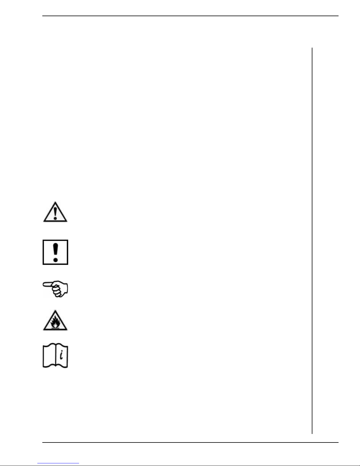
Warning
This symbol is used to highlight that non-compliance with instructions or procedures can
result in serious injuries or death to personnel.
Caution
This symbol is used to highlight that non-compliance with instructions or procedures may
cause damage to equipment.
Attention
This symbol is used to highlight and draw specific attention to important information.
Flammable or Combustible
This symbol is used to highlight and draw specific attention to flammable or combustible
materials or risks.
Reference
This symbol is used to draw attention to important information provided in Webasto or
Manufacturer Manuals.
www.webasto.us 5 Webasto Product N.A., Inc.
Page 6
Foreword
IMPORTANT SAFETY INFORMATION – Read Before Proceeding with Installation!
WARNING!
• DO NOT install fuel fired heaters in unventilated passenger compartments or confined cargo holds
• DO NOT install fuel fired heaters in engine compartments or areas where equipment must be U.S.
• DO NOT install Gasoline
• DO NOT install fuel fired heaters in the engine compartment of Gasoline
• DO NOT draw combustion air from the engine compartment of Gasoline
• ALWAYS switch fuel fired heaters off during refueling or when in a refueling area.
Air Top 2000 S, 3500 & 5000 Marine
All fuel fired heating appliances are capable of producing poisonous carbon monoxide gases. Webasto
fuel fired heaters are engineered with state-of-the-art components and safety features to precisely
control combustion and minimize the production of deadly carbon monoxide gas. Nevertheless, due to
the confined spaces within marine vessels, an increased risk of carbon monoxide poisoning causing
death or serious injury to personnel is possible if equipment is improperly installed. Therefore, it is
extremely important that you fully read and understand all installation documentation supplied with
your heater BEFORE
If you have any doubts, safety concerns or question concerning the installation documentation or the
procedures within, do not hesitate to seek professional advice from your authorized Webasto marine
dealer or Webasto Product N.A., Inc., directly at 1-800-555-4518.
unless authorized in writing by a Webasto installation specialist or Webasto Product N.A., Inc. directly.
Coast Guard rated “Ignition Proof.”
attempting installation.
fired heaters on marine vessels.
powered marine vessels.
powered marine vessels.
WARNING! - CONCERNING INSTALLATIONS IN GASOLINE POWERED VESSELS!
Installation of an auxiliary heater in gasoline powered vessels requires professional knowledge and
strict adherence to safety information, special installation instructions and restrictions. For these
reasons, installation of an auxiliary heater in gasoline powered vessels must be performed by an
authorized Webasto marine installation center. Installations must comply with all applicable American
Boat & Yacht Council recommendations and U.S. Coast Guard regulations.
CAUTION!
Location of heater, fuel system and components, wiring and control devices and installation of warm air
ducting are important for proper operation. Failure to comply with the installation instructions provided
may result in poor operation or damage to heater and vessel components.
CAUTION!
The installation instructions within this manual are intended to be used as general installation
guidelines only.
For information concerning special marine applications or marine applications you are not sure of,
contact an authorized Webasto marine dealer or Webasto Product N. A., Inc. directly at:
1-800-555-4518 (USA) or 1-800-667-8900 (Canada).
ATTENTION
It is the installer’s responsibility that the installation complies with all applicable American Boat & Yacht
Council and U.S. Coast Guard regulations. Also, all relevant state and provincial licensing regulations if
any, governing the installation and use of auxiliary heating devices in watercraft must be observed.
Webasto Product N.A., Inc. 6 www.techwebasto.com
Page 7
Air Top 2000 S, 3500 & 5000 Marine
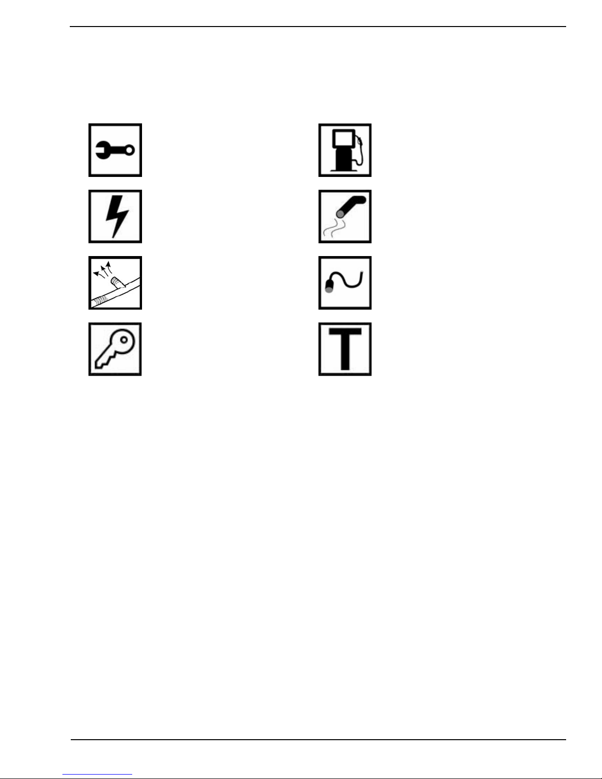
Symbol Identification
Symbols that define sections in this manual
Foreword
Mechanical Preparation
Electrical
Warm Air Ducting
Fuel
Exhaust
Combustion Air Intake
Maintenance/TroubleshootingInitial Start-up
www.webasto.us 7 Webasto Product N.A., Inc.
Page 8

Technical Data
Air Top 2000 S, 3500 & 5000 Marine
General Information
Unless tolerances are shown within the technical data table, a tolerance of ± 10% applies at an ambient temperature
of +20 °C (+68 °F) and at the rated voltage and conditions.
Fuel Requirements (Diesel/):
Diesel fuel, heating oil and kerosene are suitable fuels for the heater. Any negative effect caused by additives is not
known. Any addition of waste oil is not permitted.
When changing to cold-resistant fuels, the heater must be operated for approximately 15 minutes to ensure that the
fuel metering pump is filled with the new fuel.
Electrical Components:
Control unit, motor, fuel metering pump, light bulb in the digital timer and pencil-type glow pin are designed either for
12-volt or 24-volt operation.
The digital timer, temperature limiter and flame detector are voltage-independent components.
Heater Operation AT 2000 S D AT 3500 D AT 5000 D
Mark of Approval ~ S 306 ~ S 303
Type Air heater with vaporizing type burner (Ferro-Tec)
Heat Output Control Range
Boost (30 min.)
Fuel Diesel Diesel Diesel
Fuel Consumption Control Range
Boost (30 min.)
Rated Voltage 12/24 Volts 12/24 Volts 12/24 Volts
Operating Voltage Range 12 Volt
24 Volt
Rated Power Consumption Control Range 9-22 Watts 15-36 Watts 15-90 Watts
Permissible Ambient Temperature
Heater: - operation
- storage
Metering Pump: - operation
- storage
Control Element: - operation
- storage
Combustion Air Intake
Temperature
Setting Range for Interior
Temperature
Flow Rate of Heating Air Against
0.5 mbar
Maximum +40 °C (+104 °F)
Maximum
0.9 - 2.0 kW 1.5 - 3.5 kW 1.5 - 5.0 kW
5.5 kW
0.12 - 0.24 l/h 0.17 - 0.42 l/h 0.17 - 0.60 l/h
0.66 l/h
10 - 15 Volts
20 - 30 Volts
-40 °C ... +40 °C (-40 °F ... +104 °F)
-40 °C ... +85 °C (-40 °F ... +185 °F)
-40 °C ... +20 °C (-40 °F ... +68 °F)
-40 °C ... +85 °C (-40 °F ... +185 °F)
-40 °C ... +75 °C (-40 °F ... +167 °F)
-40 °C ... +85 °C (-40 °F ... +185 °F)
+10 °C ... +45 °C (+50 °F ... +113 °F)
3
70 m
/h 139 m3/h 218 m3/h
10.5 - 15 Volts
21 - 30 Volts
10.5 - 15 Volts
21 - 30 Volts
CO
Content in Exhaust Gas
2
(operating range maximum)
Dimensions of Heater
(Millimeters)
Weight of Heater 2.6 kg (5.73 lb) 5.9 kg (13.0 lb)
Table 1: Technical Data
Webasto Product N.A., Inc. 8 www.techwebasto.com
9.5 ... 10.5
Vol.-%
Length 311mm
Width 120mm
Height 121mm
9.5 ... 12.0 Vol.-%
Length 425mm
Width 148mm
Height 148mm
Page 9
Air Top 2000 S, 3500 & 5000 Marine
Technical Data
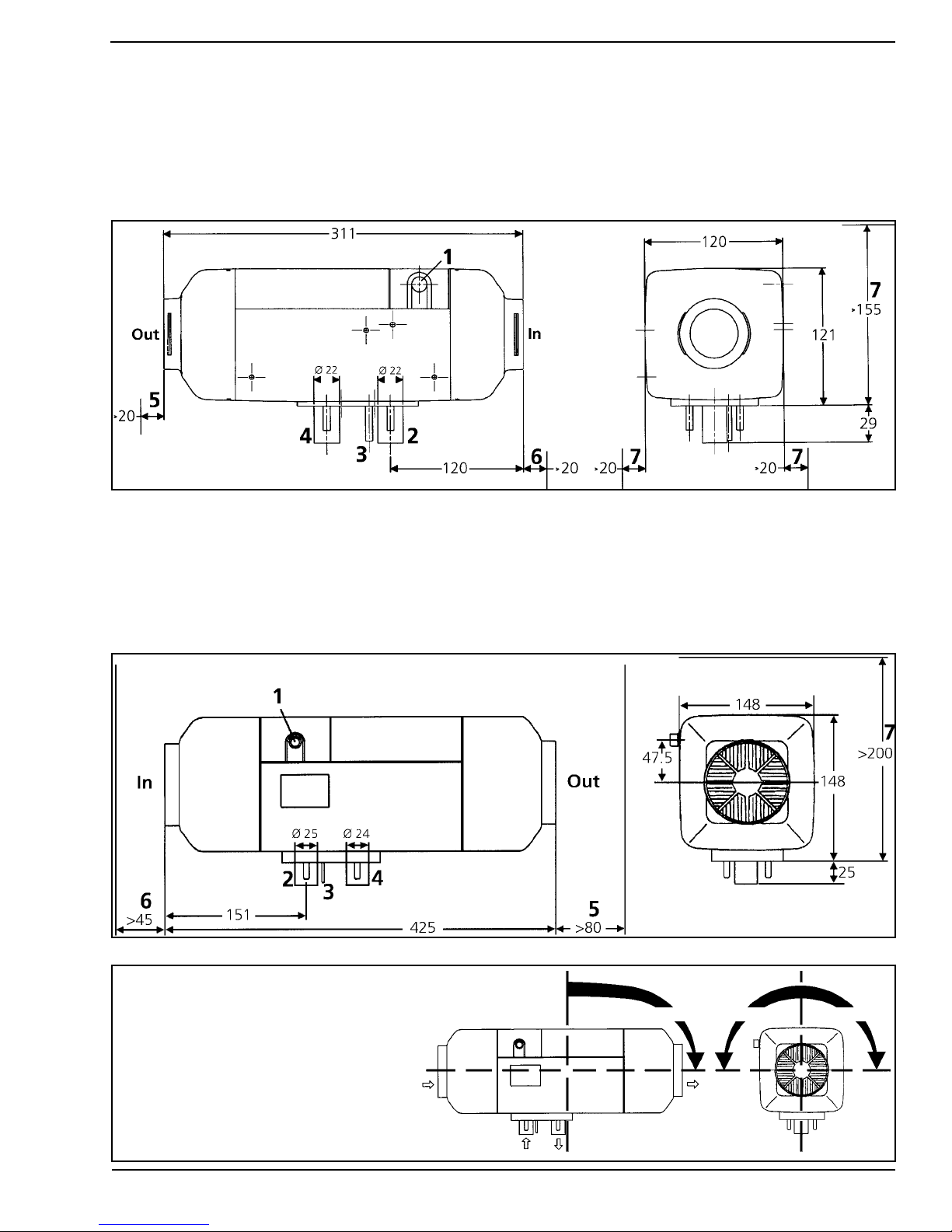
Dimensions
The mounting dimensions as well as the space required for the performance of servicing work are shown in the
following figures.
Air Top 2000 S
Legend for Air Top 2000 S (above) and Air Top 3500 & 5000 (below):
1 Electrical Cable Access (Right or Left)
2 Combustion Air Inlet
3 Fuel Inlet Tube
4 Exhaust Gas Outlet
5 Minimum Space Requirement for Warm Air Outlet
6 Minimum Space Requirement for Cool Air Inlet
7 Minimum Space Requirement for Heater Removal
Air Top 3500 & 5000
Permissible installation positions for
Air Top 2000 S, Air Top 3500 and
Air Top 5000 air heaters.
www.webasto.us 9 Webasto Product N.A., Inc.
0 – 90° 0 – 90°0 – 90°
Page 10

General Installation Overview
Air Top 2000 S, 3500 & 5000 Marine
Checklist of Minimum Requirements for the Installation of Heaters on Marine Vessels
Installation Location of Heater
• Install heater in a location that will prevent it from being submerged in the bilge water when the vessel is heeling
• As a rule, to be installed in the foredeck box or locker (to keep exhaust lines short)
Fuel Connection
• Mount the pump as closely to the fuel tank as possible (see Fig. 9, page 19)
(maximum 1.2 meter long suction line, maximum 9 meter pressure line)
• Install pump with an anti vibration, sound deadening mount
• Always use a fuel filter (see Fig. 7, page 18 and Webasto accessories)
• Do not mount pump on frames (noise transmission)
• Provide for dedicated fuel extraction, i.e. use separate tank extraction device (standpipe), do not extract fuel from
engine’s supply line. Do not “Tee” into engine fuel delivery or return lines.
Exhaust Gas System
• Exhaust gas outlet: on sailing vessels to be located at the upper stern (due to heeling) on motor boats on the sides
(owing to submerging of the upper stern)
• Install exhaust gas outlet at least 500 millimeters (20 inches) above the water line
• Always route lines with a goose-neck bend (see Fig. 4, page 15) preventing water from entering the system when
the vessel is heeling
• Always use a sealed exhaust muffler (if applicable to your installation)
• Maximum overall length of the exhaust tube is 5 meters (16.5 feet) without muffler or 2 meters (6.5 feet) with a
muffler installed.
• The total radius of bends should not exceed 270 degrees (large radii to be selected)
• Always insulate the exhaust tubes
• A condensation water drain is necessary with exhaust line lengths greater than 3 meters (10 feet) and optional on
shorter lengths (see Fig. 4, page 15) (drain to be filled with water after installation)
Combustion Air System
• Air to be drawn from ventilated foredeck box or ventilated locker or *engine room (*Diesel engines only)
• Check that intake openings are unobstructed
Heating Air Intake
• Air to be drawn from ventilated foredeck box or ventilated locker, not from the engine room (ensure that intake
openings are kept unobstructed)
• Optionally, fresh air or recirculated air may be drawn in using a distributing piece with control flap (Webasto
accessory)
Hot Air Circulation
• In the saloon, large, non-closable air outlet nozzles are to be used
• In backrooms, use small air outlet nozzles; they may be closable
• At least one air outlet nozzle with an outlet diameter appropriate for the heater must always be open
• Keep length of the air duct lines as short as possible to achieve good heat circulation without excessive flow
restriction on the heating system overall
Electrical System
• Be sure to install an external temperature sensor if air heaters are operated in the fresh-air mode
Webasto Product N.A., Inc. 10 www.techwebasto.com
Page 11
Air Top 2000 S, 3500 & 5000 Marine
Installation Example - Air Heater
General Installation Overview
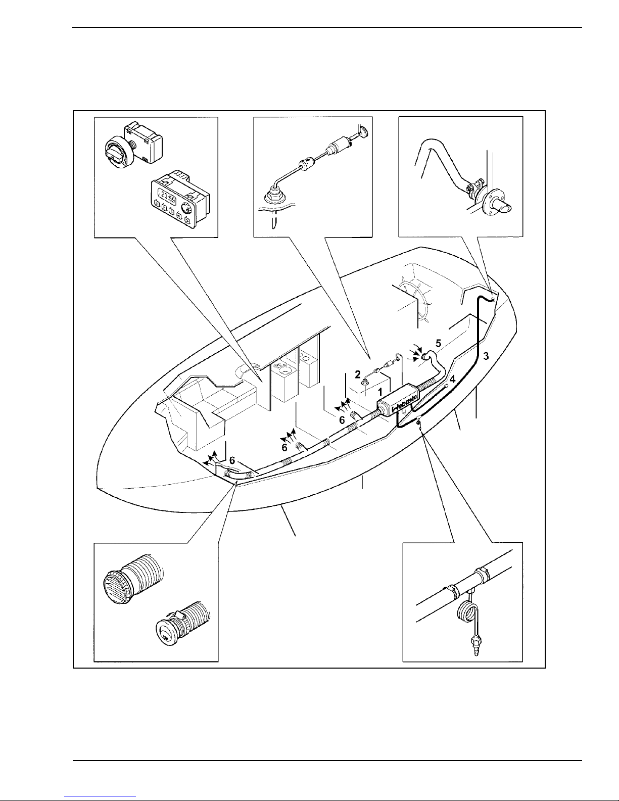
Figure 1. Installation Example - Air Heater
Legend for Figure 1:
1Air heater
2 Fuel Connection
3 Exhaust gas line
www.webasto.us 11 Webasto Product N.A., Inc.
4 Combustion air intake line
5 Cool air inlet (return)
6 Heated air outlets
Page 12

Installation
Air Top 2000 S, 3500 & 5000 Marine
Installation
In the following we would like to provide some useful advice and tips which, when followed, will ensure
that the heating system fully meets your specific needs.
The installation instruction manual supplied with the heater must always be observed.
General Installation Notes
When installing the heater, the maximum inclination of the marine vessel must be taken into account.
The heater must not be submerged, for example, in the bilge water when the vessel is in an inclined
position. The heater must be installed horizontally and parallel with the longitudinal axis of the vessel.
The positional changes that are normal during heeling are acceptable.
The installation location should not be situated next to the berths or adjacent to the salon, if possible.
The heating air (cool air return) must not be extracted from the engine room.
DO NOT store flammable material in the vicinity of the heater and its exhaust gas line. This also applies to
flammable liquids, dusts, vapors and gases.
Resilient mounting of the heater is recommended in order to absorb vibrations. In most cases, this results
in a significant noise reduction.
Positioning of the Heater
When selecting a mounting location for the heater, keep in mind storage and the movement of gear, i.e.
sail stowage, fender stowage, conduits and service access points, steering gear linkages etc.
In selecting the best mounting location, first consider all installation aspects and the constraints they will
place on the mounting location, i.e. electrical harness routing, fuel pick-up point, fuel line routing, fresh
air and heated air ducting, and most importantly, the exhaust line maximum length and outlet position
A cockpit locker or storage compartment is a favored installation area where access to the transom for the
exhaust line routing, fuel tank and fuel line, and cockpit fresh air inlet (cool air return) routing are close at
hand. Refer to Figure 1 on previous page.
As an alternative, the heater can be installed within the engine room of Diesel powered boats, however, in
this location it can be difficult to route the exhaust and other components of the heater.
Keep in mind, components such as the fresh air inlet ducting (cool air return) will have to be inspected for
damage on a regular basis to avoid engine room fumes being drawn into the warm air distribution system.
.
Special Restrictions Concerning Gasoline Powered Vessels!
WARNING!
When installing a Webasto air heater in a gasoline powered boat, the heater MUST NOT be installed in
the engine compartment. The Webasto heater must be installed above the top level of the engine
compartment.
The combustion air supply for the heater MUST NOT be drawn from the engine compartment. The inlet
end of the combustion air intake tube must be positioned above the top level of the engine
compartment to prevent the possibility of drawing flammable vapors and gases into the heater.
Webasto Product N.A., Inc. 12 www.techwebasto.com
Page 13

Air Top 2000 S, 3500 & 5000 Marine
Universal Heater Mounting Bracket
WARNING!
Drowning risk! Be absolutely sure where you are drilling or punching holes! Inadvertently drilling large
holes through the hull of a vessel below the waterline can result in massive water intake in very short
order. Always be aware of your surroundings should you have to make an escape in an emergency.
For heater mounting, use the pre-drilled stainless steel mounting bracket, which is provided with the kit.
Make certain that the bracket is mounted securely to enable the heater to withstand “sea shock.” In
some cases it may be necessary to glass fiber a wooden pad in place at the mounting location to avoid
drilling into or through the hull of the vessel.
It is also preferable to position the bracket so that the heater exhaust outlet is vertical-down. This will
provide optimum heater operation and allow for vessel’s heel.
Figure 2. Universal Heater Mounting Bracket
Place the heater on the mounting bracket. Ensure the rubber gasket on the base of the heater is in place.
Secure the heater using the four coated M6 nuts and flat washers provided.
www.webasto.us 13 Webasto Product N.A., Inc.
Page 14

Air Top 2000 S, 3500 & 5000 Marine
Exhaust System
General Information
The permissible lengths, bending radii and diameters stated in the heater manufacturer’s installation
manual for your particular heater apply to the installation of the exhaust tubing and system.
Follow the diagrams below for correct installation guidelines and ensure the exhaust tube is routed with a
minimum of bends, not to exceed 270 degrees in total and with a minimum bend radius of 50mm (2 in.).
Through-hull Fitting
The exhaust gas through-hull fitting is preferably, to be mounted at the upper stern, if possible at least
500mm (20 in.) above the water line, and must not be immersed under water even when the boat is
heeling.
The hull side is acceptable for motorboats, but bear in mind the bow wave line and beam sea risk. In all
cases, the through-hull fitting must not point in the direction of travel, or be susceptible to high wind
pressure which may blow out the heater’s flame.
A suitable hole should be drilled at a 30 degree angle in the hull for the through-hull fitting. A 6mm bar
is included in the kit to be used as an extended drilling guide for the hole saw.
Figure 3. Through-hull Fitting - Installation
Exhaust Tube Installation
Route the flexible exhaust in such a way that the heat cannot affect adjacent heat sensitive materials,
plastic piping, electric cables and sails etc. The stainless steel flexible exhaust tube supplied in the kit is
wrapped in a glass / silicon protective insulating sleeve (see Fig. 4, item 2).
If additional protection is required, we recommend over-sleeving with an additional layer of insulation
(available from your local Webasto marine dealer).
CAUTION!
DO NOT connect the heater exhaust into the engine or generator exhaust. Doing so will result in
unacceptable back-pressure levels and may damage the heater or cause operational failure.
DO NOT install a flapper valve (clamshell) over the exhaust outlet as this will cause excessive back
pressure within the exhaust system and heater.
DO NOT cover or block the exhaust outlet while the heater is in operation.
Webasto Product N.A., Inc. 14 www.techwebasto.com
Page 15

Air Top 2000 S, 3500 & 5000 Marine
The end of the exhaust gas line must be routed with a goose-neck bend and be pitched downward
toward the outlet (see Fig. 4, item 1). Any splash water that may have penetrated can thus drain back out
again and not into the heater.
The exhaust gas line is to be kept as short as possible. The maximum length of 5 meters (16.5 feet)
without muffler or 2 meters (6.5 feet) with muffler must on no account be exceeded. The total radius of
bends should not exceed 270 degrees with a minimum bend radius of 50mm (2 in.).
The exhaust tube and exhaust components must be securely fastened using approved exhaust tube
clamps and P-clips as supplied with the heater kit.
Under no circumstances should coolant hose style clamps be used to secure exhaust tubing to the heater
or other exhaust components.
If exhaust gas lines are routed through rooms occupied by persons, these pipes must be replaced with
genuine Webasto replacement parts after at least 10 years of service.
At the lowermost point of the exhaust gas line, a condensation water drain (see Fig. 4, item 3) can be
installed via which the condensation water collecting in the exhaust gas line can be drained off at regular
intervals. A condensation drain is provided in your heater kit to drain off any collected condensation or
sea water that may enter the exhaust. Fill condensation drain with water to provide a seal against exhaust
gas leakage once drain has been installed.
WARNING!
Avoid asphyxiation! If the exhaust gas tube is routed through the inside of the vessel, exhaust gas tube
must be as leakproof as possible:
- use only Webasto approved exhaust clamps and firmly tighten clamps.
- an approved exhaust sealant can be used on the inside of the exhaust tube at all connection points
- use condensation water drain
- if desired, use an optional gas tight exhaust muffler to reduce interior noise (see accessories)
Figure 4. Exhaust System
Legend for Figure 4:
1 Goose-neck (prevents water intrusion)
2 Heat insulating sleeve
3 Condensation drain-off
www.webasto.us 15 Webasto Product N.A., Inc.
Page 16

Air Top 2000 S, 3500 & 5000 Marine
Combustion Air Intake Tube Installation
WARNING!
Asphyxiation risk! The combustion air required for the heater may only be drawn in from the outside or
from spaces that are not occupied by persons e.g. ventilated foredeck box or ventilated *engine
compartment (Diesel only).
*Explosion risk! Do not draw combustion air form engine compartment of gasoline
The maximum length of the combustion air intake tube is 5 meters (16.5 feet) without a silencer or 2
meters (6.5 feet) with a silencer. On no account are these lengths to be exceeded. The total radius of
bends should not exceed 270 degrees with a minimum bend radius of 50mm (2 in.).
Where combustion air is drawn from an internal source, the combustion air tube should be routed away
from the heater with a downward pitch to prevent condensation or moisture from collecting in the tube.
Where combustion air is drawn from an external source, the end of the combustion air intake tube must
be routed with a goose-neck bend (see Fig. 5, item 1) with a downward pitch toward the outlet so that
any water that may penetrate can drain out and not into the heater. A 5mm (3/16 in.) condensation weep
hole must be provided at the lowest point between the goose-neck and the heater to allow drainage of
any trapped condensation or splash water (see Fig. 5, item 2).
powered vessels.
1
Keep combustion air intake tube
opening clear of obstructions!
2
5mm (3/16”)
Figure 5. Drain Hole - External Combustion Air Intake
To avoid pressure differences between exhaust gas outlet and combustion air inlet, the openings of the
through-hull fittings should be located in an area where equal pressure prevails.
Do not point the inlet of the combustion air tube in the direction of travel when intake air is drawn from
an external source.
Secure intake tube to heater with hose clamp provided. Ensure the fuel pump connector harness is in
place in the slot provided in the air intake port before tightening clamp. Secure the tube to adjacent
structures with P-clips or nylon wire ties.
Webasto Product N.A., Inc. 16 www.techwebasto.com
Page 17

Air Top 2000 S, 3500 & 5000 Marine
Fuel System
General Information
If you are installing the heater under the American Boat & Yacht Council, Inc. (ABYC) guidelines, the
advice of a specialist should sought.
The Fuel system conforms to Inland Waterways specifications.
Several specific regulations may apply including the use of flame resistant fuel pipe such as copper pipe,
and fire resistant fixings.
The fuel must be extracted from the fuel tank of the vessel by means of a separate fuel pick-up
(standpipe). Do not “Tee” into engine fuel delivery or return lines.
Suitable fuel extraction devices or tank pick-up devices are contained in the accessory lists for the heaters,
or are included in the heater kit.
If an additional fuel tank needs to be installed for the fuel supply of the heater, we recommend this be
carried out by a marine installation center familiar with applicable marine industry directives, codes and
standards. Any safety hazards can thus be avoided.
Fuel Standpipe Installation
The fuel standpipe should be kept 25mm (1 in.) off the bottom of the fuel tank to prevent drawing
sediment and water into the heater’s fuel system.
Legend for Figure 6:
1Nut
2 Washer
3 Rubber gasket
4 Bushing (tank-boss)
5 Tank with 25mm (1 in.) hole
1
2
3
4
5
Figure 6. Fuel Standpipe
1. Cut fuel standpipe to length, approx. 25 mm (1 in.) off bottom of fuel tank. Angle the cut to prevent
clogging.
2. Remove burrs from cut end. Apply thread sealant to threaded fittings to prevent fuel leaks.
3. Install fuel standpipe using one of the following methods:
- use 1/4 or 1/2 spare port on top of fuel tank (if available) and install standpipe
OR
- drill or punch a 25 mm (1 in.) hole in a clear area on top of the fuel tank or fuel sender plate.
(Before drilling hole, apply grease to drill bit to catch metal chips)
- assemble tank-boss and fuel standpipe to form single unit.
- install standpipe by angling unit in so that one ear of the bushing hooks under the edge of the hole.
- repeat with the other ear in the same fashion.
4. Center in hole and clamp in place by tightening nut down until gasket begins to squeeze out slightly.
6 Tank with available N.P.T. threaded port
6
www.webasto.us 17 Webasto Product N.A., Inc.
Page 18

Air Top 2000 S, 3500 & 5000 Marine
Auxiliary Fuel Tank
In the case of gasoline powered marine vessels, a separate fuel tank must be provided to supply Diesel fuel
to the Webasto air heater. Please note that gasoline
certified for marine use and must never be installed in marine vessels.
Fuel Pump and Enclosure Installation
Appropriate mounting suggestions are contained in the following installation diagrams.
The maximum permissible fuel suction height and fuel supply height for the metering pump are
referenced in Figure 9 on the next page.
CAUTION!
The fuel pump must not be mounted lower than 500 mm (20 in.) below the top of the fuel tank.
The fuel pump assembly should be mounted as close to the fuel source as possible.
The total length of fuel line run including the fuel pick-up tube to the inlet of the fuel pump must not
exceed 2 meters (78 in.) and a suction height no greater than 1 meter (39 in.).
fueled Webasto heaters are not recommended nor
On the outlet side of the pump, the fuel line must not exceed 6 meters (234 in.) and a delivery height no
greater than 3 meters (117 in.).
Ensure the fuel metering pump is mounted in a cool area. Ensure the correct direction of flow is observed.
1 2
Legend for Figure 7:
1 Fuel filter P/N 5048717A
2 Fuel outlet connection
3
3 Fuel inlet connection
4 Pulse damper
5 Electrical cable
6 Fuel metering pump
4
7 P-clip
7
6
Figure 7. Fuel Pump and Enclosure Assembly
5
Observe Figure 8 on the next page closely.
The fuel pump outlet must be as shown (check-marked images) when installing the enclosure. This will
ensure the fuel metering pump is in the correct horizontal plane for proper operation and fuel metering.
Webasto Product N.A., Inc. 18 www.techwebasto.com
Page 19

Air Top 2000 S, 3500 & 5000 Marine
Figure 8. Fuel Pump and Enclosure Installation
Fuel System Parameters
Maximum suction height (A) = 1 m (39 in.)
Maximum suction length (A + B) = 2 m (78 in.)
Maximum delivery length (C + D) = 6 m (234 in.)
Maximum delivery height (D) = 3 m (117 in.)
Figure 9. Fuel System Limitations
Fuel Lines
Link the fuel supply from the standpipe to the fuel pump and from the fuel pump to the heater using the
metal fuel tubing and compression fittings supplied with the kit. Be sure to remove any burrs from the
fuel tubing using a small file after cutting. Place the nut and olive over the end of the tubing and reassemble onto the matting component.
The compression fittings should be tightened with moderate force only, as over-tightening will lead to a
distorted olive and leaking connections.
Route the fuel tubing as straight as possible, preferably running upwards towards the heater and securely
clip at frequent intervals, away from any heat source.
www.webasto.us 19 Webasto Product N.A., Inc.
Page 20

Air Top 2000 S, 3500 & 5000 Marine
Heating Air Circuit
General Information
WARNING!
Drowning risk! Be absolutely sure where you are drilling or punching holes for ducting! Inadvertently
drilling large holes through the hull of a vessel below the waterline can result in massive water intake in
very short order.
There are two types of heating air circuits of which both have certain advantages and disadvantages over
each other. The two common types are the fresh-air mode (extracting the heating air from the outside)
and the recirculating mode (extracting the heating air from the heated room).
In the case of the fresh-air mode, exhaust air discharge openings (fans, hatches) leading to the outside are
required in every room that is heated to prevent pressurization resulting in reduced flow through the
heater. The advantage of this operating mode is that fresh air is constantly introduced with a reduction in
humidity, as compared to the recirculating mode.
The recirculating mode of operation requires return air openings leading to the heating air intake ducting
socket of the heater so that the heating air can flow back to the heater to facilitate proper air circulation.
The advantage of this operating mode lies in the faster heating action through better heat utilization.
The total free cross-sectional area of the return air openings (or exhaust air openings of the rooms heated)
must be at least 1.5 times the size of the cross-sectional area of the heating air intake opening on the
heater.
Irrespective of the position of the heating air inlet it must be ensured that no water can penetrate and that
the intake openings are not and cannot be obstructed by any objects stowed away.
Webasto air heaters feature powerful blowers that are capable of conveying the heating air through long
ducting runs for distribution throughout the vessel. Nevertheless, keep ducting runs and turns to a
minimum. Plan your heating circuit carefully to avoid high flow resistance. If flow resistance is too high,
the overheat protection will likely respond by switching the unit off.
Optional ducting system silencers are available to reduce any associated noise to a minimum.
The heating air circuit must be so designed that the heating air ducting can neither be crushed nor
pinched.
Where heating air ducts need to be routed through bulkheads the use of pipe sockets is recommended so
that the ducts can be attached on both sides. Ducting hoses that are merely passed through the openings
without any protection will wear through with time.
When installing heating air ducting in a wet environment we recommend the use of spiral wire reinforced
ducting.
The use of closable air outlet nozzles is only allowed on branch lines (side rooms).
In air heating systems, manifolds with control flaps and cable control are frequently used. The air flow can
thus be distributed and adjusted by infinitely variable control.
Our accessories list contains all air circulation elements available (branches, elbows, etc.).
Webasto Product N.A., Inc. 20 www.techwebasto.com
Page 21

Air Top 2000 S, 3500 & 5000 Marine
Heating Air Ducting Installation
Figure 10 illustrates the installation of an air heater in a sailboat with heating air intake from the cockpit.
Figure 11 illustrates the installation of an air heater with recirculating mode of operation in a sailboat.
Figure 10. Installation Diagram of an Air Heater with Fresh Air Mode of Operation
Figure 11. Installation Diagram of an Air Heater with Recirculating Mode of Operation
www.webasto.us 21 Webasto Product N.A., Inc.
Page 22

Air Top 2000 S, 3500 & 5000 Marine
Heating Air Intake Options
Option 1, Recirculation Mode:
The return air for heating is drawn in from the cabin (and any side-rooms) either via flexible ducting or
return openings. Use a Webasto fixed open grille to terminate the flexible duct. If the heater is mounted
in a locker, use the grille supplied in the kit to ventilate the locker.
Locate the air intake grille close to the heater intake, so that outside air is drawn in, in preference to the
locker air. It is not necessary to connect the grille to the heater with flexible ducting, unless there is a risk
of contaminated air reaching the heater.
If the heater is fitted in the engine room, use flexible ducting to draw in fresh cabin air, thus, avoiding
engine room air and associated fumes from being drawn into the heating air system.
Option 2, Fresh Air Intake Mode:
The air for heating is drawn into the heater from an external source either via flexible ducting or a grille
located on an external locker wall or wall opening. It is important that the rooms being heated are
adequately ventilated, otherwise air flow through the heater will be reduced, in which case the heater’s
overheat protection is likely to respond.
WARNING!
Asphyxiation risk! The fresh air intake must be located where exhaust fumes from the heater or the
engine cannot be drawn in to the heater intake and heating system.
To control the room temperature in the case of fresh air intake, an optional external temperature sensor
must be installed in a location with average room temperature and be connected to the control unit.
ATTENTION
IT IS IMPORTANT THAT A SUPPLY OF CLEAN, UNOBSTRUCTED AIR REACHES THE HEATER THROUGHOUT
ITS OPERATION.
Hot Air Outlets
Hot air outlets should be located low in the rooms being heated. Be aware that the heated air discharged
can reach temperatures upwards to 90 °C (200 °F). Outlets should be located where contact with
passengers is unlikely. The hot air discharge should not be directed towards heat sensitive components or
surfaces in the immediate vicinity of the outlet.
Avoid long runs of ducting; they are inefficient and could lead to over heating.
A heater is more efficient when venting the hot air into free cabin space rather than being confined to a
“rabbit warren” of ducting.
It is not always necessary to place outlets at every point where heat is desired. The pressure of the fan,
(particularly with minimal ducting), is effective at reaching most parts of the vessel.
Keep the duct runs as straight as possible and avoid running ducts where they could become crushed or
broken.
The following diagrams illustrate typical ducting systems created with “Y” or “T” branches and outlets.
Use the clips provided to secure duct joints.
Webasto Product N.A., Inc. 22 www.techwebasto.com
Page 23

Air Top 2000 S, 3500 & 5000 Marine
Ducting Layouts - Typical
2 3 4 5 6
1
7
8
1 Open Air Inlet Nozzle - 60mm P/N 398551
2 Ducting - 60mm. . . . . . . . . . . P/N 398497
3 Ducting - 60mm. . . . . . . . . . . P/N 398497
4 T-Junction - 60x60x60mm . . . P/N 86643A
Figure 12. Air Top 2000 / 2000 S - Typical 2 Outlet Ducting Layout
2 6
12
5 Ducting - 60mm . . . . . . . . . . . P/N 398497
6 Air Outlet Nozzle - 60mm . . . . P/N 398551
7 Ducting - 60mm . . . . . . . . . . . P/N 398497
8 Air Outlet Nozzle - 60mm . . . . P/N 398551
5
11
10
7
81 3 4
9
1 Open Air Inlet Nozzle - 90mm P/N 91569A
2 Ducting - 90mm x 1.5m . . . . . P/N 5000266A
3 Ducting - 90mm x 1.5m . . . . . P/N 5000266A
4 Y-Junction - 90x60x90mm . . . P/N 90999A
5 Ducting - 90mm x 5m . . . . . . P/N 5000753A
6 Y-Junction - 90x60x90mm . . . P/N 90999A
Figure 13. Air Top 3500 - Typical 3 Outlet Ducting Layout
See “Accessories” section of this manual for a listing of additional ducting accessories.
www.webasto.us 23 Webasto Product N.A., Inc.
7 Ducting - 90mm x 5m. . . . . . . P/N 5000753A
8 Open Outlet Nozzle - 90mm . . P/N 91569A
9 Ducting - 60mm x 2m. . . . . . . P/N 5000316A
10 Air Outlet Nozzle - 60mm . . . . P/N 398551
11 Air Outlet Nozzle - 60mm . . . . P/N 398551
12 Ducting - 60mm x 2m. . . . . . . P/N 5000316A
Page 24

Ducting Layouts - Continued
Air Top 2000 S, 3500 & 5000 Marine
2 6 7 91 3 4 5
15
1 Open Air Inlet Nozzle - 90mm P/N 91569A
2 Ducting - 90mm x 1.5m . . . . . P/N 5000266A
3 Y-Junction - 90x60x90mm . . . P/N 90999A
4 Ducting - 90mm x 1.5m . . . . . P/N 5000266A
5 Y-Junction - 90x60x90mm . . . P/N 90999A
6 Ducting - 90mm x 5m . . . . . . P/N 5000753A
7 Y-Junction - 90x60x90mm . . . P/N 90999A
8 Ducting - 90mm x 5m . . . . . . P/N 5000753A
Figure 14. Air Top 5000 - Typical 4 Outlet Ducting Layout
9 Air Outlet Nozzle - 90mm . . . . P/N 91569A
10 Ducting - 60mm x 2m. . . . . . . P/N 5000316A
11 Air Outlet Nozzle - 60mm . . . . P/N 398551
12 Ducting - 60mm x 2m. . . . . . . P/N 5000316A
13 Air Outlet Nozzle - 60mm . . . . P/N 398551
14 Air Outlet Nozzle - 60mm . . . . P/N 398551
15 Ducting - 60mm x 2m. . . . . . . P/N 5000316A
13
8
10
1214
11
See “Accessories” section of this manual for a listing of additional ducting accessories.
Webasto Product N.A., Inc. 24 www.techwebasto.com
Page 25

Air Top 2000 S, 3500 & 5000 Marine
Electrical System
General Information
Electrical connections are to be carried out in accordance with the circuit diagrams contained in this
installation manual.
2
Main power leads must have a minimum cross-sectional area of 4.0 mm
should be routed a short as possible. In the case of lead lengths greater than 7.5 m (24.5 ft.), the
existing cables with 4.0 mm
2
wires must be replaced with 6.0 mm2 (AWG 8 Gauge) wires.
The main fuse has to be installed at a distance no greater than 1 m (39 in.) from the battery
positive pole.
When installing the electrical system make sure that the components are installed in protected, dry areas
to prevent corrosion. When leads need to be extended, make sure you use cables with the correct crosssectional area!
We recommend a second battery to be installed for the operation of the heater which should, if possible,
not be used for engine starting purposes. To avoid having to charge the battery too often its capacity
should not be too small.
(AWG 10 Gauge) and
If you have highly sensitive electronic components on board, a special electrical interference suppression
may become necessary. In this case, please consult a competent specialist workshop.
When actuating the battery disconnect switch (if equipped), wait until the after-running period of the
heater has been completed.
Harness Connection
Figure 15. Control, Battery, and Fuel Pump Electrical Harnesses - Air Top Heaters
The fuel pump harness can be connected directly to the fuel pump without the extension if the pump is
mounted close to the heater, otherwise, use the extension as shown in Figure 15.
The heater power / control harness can be routed out of the right or left hand side of the heater subject to
individual requirements.
www.webasto.us 25 Webasto Product N.A., Inc.
Page 26

Air Top 2000 S, 3500 & 5000 Marine
ATTENTION
Be sure not to touch the printed circuit board or conductors. Care should be taken to prevent discharge
of static electricity that can damage sensitive circuitry.
Remove the control unit cover to access the harness connection sockets. Insert harness connectors into
their relative sockets.
NOTE:
Lift off control unit cover by applying a blunt
edge at its side (see arrows in Figure 16).
Figure 16. Removal of Control Unit Cover
The Air Top 2000 S will have an eight-way socket whereas the Air Top 3500 & 5000 will have a twelve-way
socket.
Refit the control unit cover with the harness grommet in place.
Locate a suitable battery supply and ground point. The closer you can connect the main power leads to
the battery, the less likelihood of voltage drop problems affecting heater operation. Route and connect
the power leads, with ring terminals, as follows:
Red - battery positive or power supply point (+)
Brown - battery negative or ground point (–)
Fuse Holder Installation
To provide the heater with adequate protection, an additional flat fuse holder is to be installed (supplied
with the heater). The fuse holder must be mounted within 1 meter (39 in.) of the positive power source
or closer if possible.
The fuse holder may only be installed in an interior space protected from splash water or damage. Mount
the fuse holder in an upright position, see Figure 18 for installation position variance. Secure the fuse
holder mounting plate to a flat surface and clip the fuse holder into the mounting plate.
Figure 17. Fuse Holder, Installation Position
Webasto Product N.A., Inc. 26 www.techwebasto.com
Page 27

Air Top 2000 S, 3500 & 5000 Marine
Control Element (Rheostat) Installation
ATTENTION
Since the control element is not affected by temperature, it can be mounted virtually anywhere suitable
within the vessel as long as it can be easily reached by the user during heater operation.
Install control element in a suitable location allowing enough slack in the harness so that it is not stretched
taut. The shaft will require a 12.5 mm (1/2 in.) hole for mounting. Observe the figures below for
mounting. Plug harness connector into receptacle on rear of control element.
Figure 18. Heater Control Knob
Correct!
Figure 19. Mounting of Heater Control Knob
Incorrect! (shaft set too high)
Figure 20. Mounting of Heater Control Knob (Incorrect)
www.webasto.us 27 Webasto Product N.A., Inc.
Page 28

Air Top 2000 S, 3500 & 5000 Marine
Initial Start-up
Before starting the heater for the first time, check your installation for:
• routing and securing of wiring, fuel line, exhaust/combustion air tubes and hot air outlet/return
air ducting.
• battery connections and polarity.
• loose fasteners.
Control Range
Off
Indicator
Figure 21. Control Element Knob Range
Once the installation has been inspected, insert the main power fuse and set the control element knob to
the maximum heat position (see Figure 21).
The heater may run through a few start-up attempts without actually firing up. Depending on the total
length of fuel line, it may take a few start attempts before the fuel reaches the heater. This is normal after
switching on for the very first time. Switch the heater off and back on again to clear the lock-out and reinitiate the start-up cycle after each failed attempt.
Once the heater starts, allow it to run until all trapped air bubbles have escaped and heater operation
sounds smooth and consistent.
Knob
Maximum
After the heater is in normal operation, all fuel connections must be checked once again for leakage and
all lines, tubes and wiring for secure fastening.
Using the information from the heater identification plate, complete the warranty registration card and
send to Webasto Product N.A., Inc. for warranty registration.
Webasto Product N.A., Inc. 28 www.techwebasto.com
Page 29

Air Top 2000 S, 3500 & 5000 Marine
Maintenance/Troubleshooting
WARNING!
Although simple maintenance procedures can be performed by the owner, any operational problems or
major repairs due to damage should be performed by a properly trained Webasto specialist.
CAUTION!
Always use genuine Webasto service and replacement parts to ensure trouble-free operation of the
heater.
Heater Maintenance
The Webasto Air Top series air heaters are designed and engineered with minimal maintenance in mind.
Under normal circumstances it should be inspected for proper functioning at least once annually,
preferably, just prior to the heating season.
To ensure trouble-free operation, the following should be part of an annual and periodical inspection:
• Operate the heater a minimum of 10 minutes every month to keep fresh fuel in the system and
the fuel pump lubricated.
• Keep the heating air outlet and ducting clear of obstructions. Inspect outlet ducting for damage
and repair as necessary.
• Keep the heater inlet grille clear of obstructions. If the heater is equipped with ducting, inspect
for damage and repair as necessary.
• Inspect the combustion air tube and exhaust tube for obstructions and damage. Check to ensure
they are securely attached to the heater and vehicle. Repair damaged items where necessary.
• Inspect the fuel system and all connections for leaks. Tighten clamps if loose. Ensure fuel line is
well secured to the vehicle. Replace fuel filter if equipped.
Troubleshooting
ATTENTION
Advanced troubleshooting requires comprehensive knowledge about structure and theory of operation
of the heater components and should only be performed by authorized Webasto trained specialists.
For the purpose of this manual, only those items as they pertain to installation will be covered under
troubleshooting.
For malfunctions beyond the scope of this manual, please call Webasto Product N. A., Inc. directly at
1-800-555-4518 (USA) or 1-800-667-8900 (Canada).
In the event of a heater malfunction, first check the following two items to eliminate them as cause for
trouble:
1. Power Supply
- Fuse blown?
- Power at fuse?
2. Fuel Supply
- Fuel in tank?
- Clean, unrestricted fuel supply?
www.webasto.us 29 Webasto Product N.A., Inc.
Page 30

Air Top 2000 S, 3500 & 5000 Marine
Heater Shuts Off Automatically
The heater will automatically shut off if a malfunction occurs. To clear a malfunction, turn the control
element knob to off, wait 2 seconds and turn on once again to reset the heaters control unit. Should the
heater fail to start or continues to malfunction, consult your Webasto specialist.
Heater Emits Black Smoke from Exhaust
Check the combustion air intake tube and exhaust tube for obstructions or damage. Clear obstructions as
necessary or replace damaged tubes. Should condition persist, consult your Webasto specialist.
Self-Diagnostic System (Reading Flash Codes)
A flash code will be generated on the indicator light of the control element. These flash codes indicate a
malfunction and subsequent operational interruption. There are up to ten codes available depending on
the nature of the malfunction and the heater model (see Table 2).
In order to make a correct analysis, it is necessary to understand the flash code event. The flash code
pertains to the control element (switch) only. The flash code is only visible during the after-run (cooldown) period of operation (an optional timer will hold the last code in memory until corrected, see “F”
codes in parentheses on Table 2).
During the flash code event, you will see five quick flashes followed by a slower sequence of flashes from
one flash up to ten flashes. The slower sequence of flashes is the actual malfunction code. The five quick
flashes are only an indication that a malfunction has been detected and that the code will be displayed.
Count only the slower sequence of flashes to obtain the current malfunction code.
For example ( = one flash):
Event code 4X (F 04): ... ... ... ...
The fast/slow sequence will be repeated until the heater completes the after-run (cool-down) cycle after
which, the code will be stored in the control unit memory.
ATTENTION
Specialized diagnostic equipment is required to read malfunction codes stored in the control unit
memory. Consult your Webasto specialist for details.
ATTENTION
After any correction of a malfunction, a functional test has to be performed with the heater installed in
the vessel.
ATTENTION
Ambient air temperature must be below the set point on the control element knob before heater will
start operation.
Webasto Product N.A., Inc. 30 www.techwebasto.com
Page 31

Air Top 2000 S, 3500 & 5000 Marine
Diagnostic Code Table
Symptom Probable Cause Check and Correct
No Function Electrical wiring, fuses
Control unit
1X Flash (F 01)
No start after 2 start
attempts No flame-up
2X Flashes (F 02)
Flame-out during
operation
3X Flashes (F 03)
Low or over voltage for
more than 20 seconds
4X Flashes (F 04)
Premature flame
detection
5X Flashes (F 05)
(Air Top 2000 S Only)
Flame sensor
6X Flashes (F 06)
Temperature sensor
7X Flashes (F 07)
Fuel metering pump
8X Flashes (F 08)
Combustion air fan
9X Flashes (F 09)
Glow pin
(Ceramic igniter)
10X Flashes (F 10)
Overheating
11X Flashes (F 11)
(Air Top 3500/5000 Only)
Temperature limiter
12X Flashes (F 12)
(Air Top 3500/5000 Only)
Control element
Fuel system
Combustion air
Burner
Fuel supply (shortage)
Burner
Electrical system Load test batteries
Defective flame sensor
Defective flame sensor/
glow pin
Wiring
Defective flame sensor
Wiring
Defective temp. sensor
Wiring
Defective fuel pump
Wiring
Wrong RPM
Defective fan motor
Wiring
Defective glow pin
Defective flame sensor/
glow pin
Overheating
Air flow
Wiring
Defective temp. limiter
Wiring
Defective temp. limiter
Wiring
Defective control element
Fuses, battery connections
Power at red wire, ground at brown wire
Control unit malfunction
Fuel level - No fuel - Fuel system not primed
Type of fuel being used
Plugged fuel filter - replace
Fuel line connections and clamps loose
Air intake or exhaust - restricted or plugged
Clean or replace burner unit
Restriction in fuel system
Plugged fuel filter - replace
Fuel line connections and clamps loose
Type of fuel being used
Clean or replace burner unit
Corrosion at connections
Loose connections
Replace flame sensor - Air Top 2000 S only
Replace flame sensor/glow pin - Air Top 3500/5000
only
Damaged or corroded wiring, open or short circuit
Replace flame sensor
Damaged or corroded wiring, open or short circuit
Replace temperature sensor
Damaged or corroded wiring, open or short circuit
Replace fuel pump
Damaged or corroded wiring, open or short circuit
Replace combustion air fan
Replace combustion air fan
Damaged or corroded wiring, open or short circuit
Replace glow pin - Air Top 2000 S only
Replace flame sensor/glow pin - Air Top 3500/5000
only
Switch heater off and back on (see air flow)
Motor/fan obstruction, heating air flow blocked
Damaged or corroded wiring, open or short circuit
Replace temperature limiter
Damaged or corroded wiring, open or short circuit
Replace temperature limiter
Damaged or corroded wiring, open or short circuit
Replace control element
Table 2: Diagnostic Codes - Air Top Heaters
www.webasto.us 31 Webasto Product N.A., Inc.
Page 32

Schematics
Air Top 2000 S, 3500 & 5000 Marine
Wiring Schematic - Air Top 2000 / 2000 S with Control Element (Rheostat)
Figure 22. Wiring Schematic - Air Top 2000 / 2000 S (12 and 24 Volt)
A1 Air Top 2000
A2 Control Unit
B1 Flame Sensor
B2 Air Temperature Sensor
B3 Temperature Limiter
E Glow Pin
F1 Fuse - 24V 10A or 12V 15A
H1 Indicator Light (in item S1)
M Motor
S1 Control Element
X1 Connector 2-Pin (Motor)
X2 Connector 2-Pin (Fuel Pump)
Webasto Product N.A., Inc. 32 www.techwebasto.com
X3 Connector 2-Pin (Flame Sensor)
X4 Connector 2-Pin (Glow Pin)
X5 Connector 2-Pin (Temp. Limiter)
X6 Connector 8-Pin (Main Harness)
X7 Connector 2-Pin (Fuel Pump)
X8 Connector 2-Pin (Fuel Pump)
X9 Connector 2-Pin (Temp. Sensor)
X10 Connector 8-Pin
X11 Connector 4-Pin
X12 Diagnostic Link
Y1 Fuel Metering Pump
Page 33

Air Top 2000 S, 3500 & 5000 Marine
Wiring Schematic - Air Top 3500 / 5000 with Control Element (Rheostat)
Schematics
Figure 23. Wiring Schematic - Air Top 3500 / 5000 (12 and 24 Volt)
A1 Heater - Air Top 3500 / 5000
A2 Control Unit
B2 Temperature Sensor
B3 Temperature Limiter
E Ceramic Igniter / Flame Detector
F1 Flat Fuse - 15 Amp
H1 Operation Indicator
M1 Fan Motor
S1 Control Element (On - Off Switch and
Temperature Controller)
X1 2-pin Connector - Fan Motor
www.webasto.us 33 Webasto Product N.A., Inc.
X2 2-pin Connector - Ceramic Igniter / Flame Detector
X3 2-pin Connector - Temperature Limiter
X4 2-pin Connector - Fuel Pump
X5 2-pin Connector - Temperature Sensor
X6 2-pin Connector - Not Used
X7 12-pin Connector - Main Harness Connection
X8 2-pin Connector - Diagnostic Link
X9 4-pin Connector - Control Element
X10 2-pin Connector - Fuel Pump Harness
X11 2-pin Connector - Fuel Pump Harness
Y1 Fuel Dosing Pump
Page 34

Accessories
Air Top 2000 S, 3500 & 5000 Marine
Air Top 2000 S
Part Number Description
88206A . . . . . . . . . .7-Day Digital Timer Model 1531 with 3 Programmable Settings and Temperature Control
398551 . . . . . . . . . . Hot Air Outlet Nozzle with 360 Degree Directional Adjust - 60 Millimeter
87389A . . . . . . . . . .Return Air Inlet or Hot Air Outlet (Flat Mount - Non Directional) - 60 Millimeter
86643A . . . . . . . . . .Tee Junction - 60 x 60 x 60 Millimeter
5000258A . . . . . . . .Ducting - 60 Millimeter Diameter by 0.5 Meter Length
900497A . . . . . . . . .Ducting - 60 Millimeter Diameter by 1 Meter Length
5000693A . . . . . . . .Ducting - 60 Millimeter Diameter by 1.5 Meter Length
5000316A . . . . . . . .Ducting - 60 Millimeter Diameter by 2 Meter Length
5000692A . . . . . . . .Ducting - 60 Millimeter Diameter by 3 Meter Length
5000318A . . . . . . . .Ducting - 60 Millimeter Diameter by 10 Meter Length
7-Day Digital Timer P/N 88206A
60mm
60mm
60mm
Tee Junction P/N 86643A
60mm
Webasto Product N.A., Inc. 34 www.techwebasto.com
360 Degree Directional Hot Air Outlet
P/N 398551
Page 35

Air Top 2000 S, 3500 & 5000 Marine
Accessories
Air Top 3500 / 5000
Part Number Description
88206A . . . . . . . . . 7-Day Digital Timer Model 1531 with 3 Programmable Settings and Temperature Control
91569A . . . . . . . . . Return Air Inlet or Hot Air Outlet (Flat Mount - Non Directional) - 90 Millimeter
87389A . . . . . . . . . Hot Air Outlet (Flat Mount - Non Directional) - 60 Millimeter
398551. . . . . . . . . . Hot Air Outlet Nozzle with 360 Degree Directional Adjust - 60 Millimeter
90999A . . . . . . . . . Wye Junction - 90 x 60 x 90 Millimeter
5000264A . . . . . . . Ducting - 90 Millimeter Diameter by 0.5 Meter Length
5000265A . . . . . . . Ducting - 90 Millimeter Diameter by 1 Meter Length
5000266A . . . . . . . Ducting - 90 Millimeter Diameter by 1.5 Meter Length
5000753A . . . . . . . Ducting - 90 Millimeter Diameter by 5 Meter Length
5090395A . . . . . . . Ducting - 90 Millimeter Diameter by 25 Meter Length
5000258A . . . . . . . Ducting - 60 Millimeter Diameter by 0.5 Meter Length
900497A . . . . . . . . Ducting - 60 Millimeter Diameter by 1 Meter Length
5000693A . . . . . . . Ducting - 60 Millimeter Diameter by 1.5 Meter Length
5000316A . . . . . . . Ducting - 60 Millimeter Diameter by 2 Meter Length
5000692A . . . . . . . Ducting - 60 Millimeter Diameter by 3 Meter Length
5000318A . . . . . . . Ducting - 60 Millimeter Diameter by 10 Meter Length
60mm
60mm
90mm
Hot Air Outlet P/N 87389A
90mm
www.webasto.us 35 Webasto Product N.A., Inc.
90mm
Wye Junction P/N 90999A
Return Air Inlet or Hot Air Outlet
P/N 91569A
Page 36

Org. 01/2004 Rev. N/A P/N 5000700A
Webasto Product N.A., Inc.
15083 North Road
Fenton, MI 48430
Technical Assistance Hotline
USA: (800) 555-4518
Canada: (800) 667-8900
www.webasto.us
www.techwebasto.com
 Loading...