

Page 1
Operating and servicing
instructions
Air Top 2000
Webasto AG
Kraillinger Strasse 5
http://www.webasto.de
- 82131 Stockdorf
General information
Dear Webasto user
We presume that the principle and mode of operation of your new heater has been
explained to your complete satisfaction by the workshop / service centre which
installed the heater. This manual summarizes the main points of importance for using
the heaters Air Top 2000.
Maintenance and safety instructions
The heater has been type-tested and approved in accordance with EC
Air Top 2000
Directives 72/245/EEC (EMC) and 2001/56/EC (heater) with the following EC permit
numbers:
e1*72/255*95/54*1085*--
e1*2001/56*0013*--
NOTE:
The provisions of these Directives are binding within the territory governed by EU
Directive 70/156/EEC and should similarly be observed in countries without
specific regulations!
The heaters must be installed as described in the installation instructions. The
installation must be tested in compliance with the statutory regulations for the installation.
For further details refer to the installation instructions.
The year in which the heater was used for the first time must be permanently displayed
on the factory plate be deleting the inapplicable years from the plate.
The heaters are not designed for heating hazardous substance transport
compartments.
requirements of ADR/RID part 9 para. 9.2.4.7 Combustion heating systems, must also
be satisfied.
Keep the hot air inlet and hot air outlet free of dirt and foreign bodies.
Contaminated or blocked hot air lines may cause overheating and thus result in the
overheating cut-out tripping.
Do not stand on the heater and do not place any heavy items on the heater or throw
items at the heater.
Do not place any items of clothing, textiles or similar materials over the heater or in front
of the hot air inlet and the hot air outlet.
The current of hot air in the heater must not be restricted or blocked by highly
inflammable substances or materials such as rags, cleaning wool, etc.
To install the Air Top 2000 heater in hazchem vehicles, the
The heater must not be operated:
n
at filling stations or tank farms.
n
in places where inflammable vapours or dust may form
!
Risk of explosion
and asphyxiation
(for example near fuel, coal, wood dust or cereal stores).
n
in enclosed areas (for example garages), not even if you
use the timer or Telestart.
The heater :must not
nnbe exposed to temperatures over +85°C. If it is exposed
to temperatures above this level the electronics may
D
suffer permanent damage.
be cleaned using a high pressure cleaner.
The heater :must
n
be operated with the fuel specified by the manufacturer
(petrol for the Air Top 2000 B heater). Both leaded and
unleaded fuel may be used.
It must be operated with the fuel specified by the
manufacturer (diesel for the Air Top 2000 D heater).
Class EL heating oil (not L heating oil) may also be used
as long as it complies with the normal quality available on
G
the German market pursuant to DIN 51603.
The Air Top 2000 D heater may also be operated using
PME (bio diesel), which complies with DIN EN 14124.
We know of no negative influences due to additives.
If fuel is extracted from the vehicle's tank, follow the
additive instructions issued by the vehicle manufacturer.
If you change to low-temperature fuel, the heater must be
operated for approx. 15 minutes so that the fuel system is
filled with the new fuel.
n
be shut down by removing the fuse if lots of smoke,
unusual combustion noise or a smell of fuel develops.
Do not restart it until the heater has been tested by
Webasto-trained personnel.
n
be started at least one per months with a cold engine and
at the lowest blower setting for 10 minutes. The heater
must be checked by an expert at the latest at the start of
the cold weather.
Ident-Nr. 9011427A 05/0406
Page 2
Liability claims:
nnFailure to follow the installation instructions and the notes
contained therein will lead to all liability being refused by
Webasto. The same applies if repairs are carried out
incorrectly or with the use of parts other than genuine
spare parts. This will result in the invalidation of the type
approval for the heater and therefore of its homologation /
EC type licence.
Liability claims will only be accepted if the claimant can
verify that he has complied with the servicing and safety
instructions.
The heat exchanger in the air heater can be used for a maximum of 10 years and
must then be replaced by the manufacturer or one of its contract workshops using
a genuine spare part.
If exhaust lines pass through areas used by personnel they must also be replaced
by genuine spare parts after 10 years.
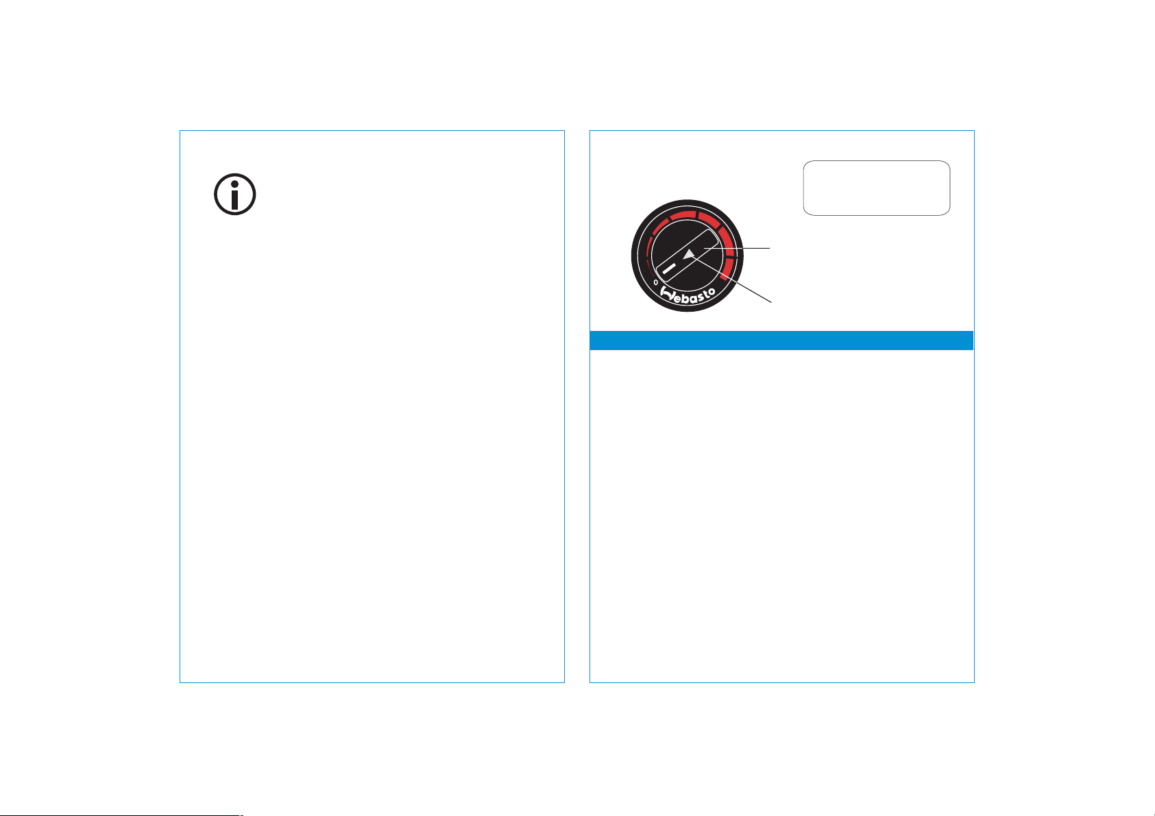
Control element
Changes to the settings
on the control element
are implemented after
!
a delay.
Rotary knob for:
- Switching on and off
- Setting the room temperature
Resetting after a fault cut-out-
Indicator / Error code display
To switch on
Set the rotary knob on the control element to the required temperature.
NOTE:
To prevent the hot and combustion air fan from blocking or scraping, ensure that
there are no objects on or against the heater before you switch it on.
!
NOTE for ADR operation only:
The Air Top 2000 heater is switched on and off by hand using a switch. Automatic
controls must not be used.
In class FL vehicles these heaters must not be used during loading and unloading
procedures or at loading points.
In class FL vehicles the heaters are switched off automatically and the combustion air
supply is interrupted for a maximum of 40 seconds if:
– the vehicle's engine is at a standstill; in this case the heater can be switched on
again by hand.
– a pumping device that is part of the vehicle is started. The control unit is then in fault
lock-out mode.
The ON/OFF switch must be set to OFF before the heater can be restarted.
!
Page 3

Combination timer
Day
Program number
Time
Combination
timer
MO
2
Indicator
Temperature
selector
Switch on
Switch off
Set time/date
View time
Manual: Press the button (permanent heating mode)
Automatic: By programming the start time
Manual: Press the button again
Automatic: By programming the operating period
When the heater is operating: By setting the remaining time
Press the button for more than two seconds the time will flash
set the time using the and buttons the day will flash set the
day.
Ignition off: Press button.
--
--
General
Operation
Error code
Program selector
Immediate
Return
Forward
heat
The combination timer allows the heater start time to be selected for
a period of up to seven days. Three cut-in times can be programmed,
although only one of them may be activated.
The combination timer has a temperature setpoint generator.
When the ignition is switched on the timer shows the current time
and the day. If the heater is operating the display and the buttons
are lit.
When the timer is connected to the power supply all the symbols in
the display will flash. The time and day must be set. The display
remains blank in ADR vehicles.
The operation of the timer is designed such that all the flashing
symbols can be adjusted using the and buttons. If no button is
pressed for five seconds the displayed time is saved. If the and
are pressed for longer than two seconds, they will switch to high
speed adjustment.
If the ignition is switched off whilst the heater is in permanent heating
mode, a remaining operating time of 15 minutes will appear on the
display and the heater will continue to operate.
On heaters that output an error code (Air Top 2000),
a number, the error code, may appear in the display. In this case you
should visit a Webasto service outlet.
Program
Start time
View/Delete
selected
times
Program
operating
time
Set remaining
time
Remote control
Vehicles with
ADR
equipment
Press button program number will flash set the start time using
the and buttons the day will flash set the day.
If you press the button several times you can set program
numbers 2 and 3 or go to time mode.
Press the button several times until the required program number
is displayed.
To delete the selected time press the button until the time is
displayed with no program numbers.
The heater must be switched off. Press the button for three
seconds the operating duration will flash set the required operating
duration using the and buttons (10 to 120 minutes).
Set the required remaining time (1 to 120 minutes) using the
and buttons. The remaining time is the time that the heater will
continue to operate. It can only be changed whilst the heater is
operating and the ignition is off.
Possible using an external optional immediate heat button.
It is not possible to set a time on ADR vehicles. The remaining time
will be shown on the display whilst the heater is operating. The time
can be adjusted.
--
--
-
--
Page 4

Troubleshooting Error code output on combination timer or control element
If an error occurs, first check the fuse and plug connections to ensure that they are in
perfect condition and connected correctly.
If the action described below does not rectify the error, have the heater checked by
Webasto-trained personnel.
Heater cuts out automatically
Cause
No combustion after start
and repeat start
Flame extinguishes during
operation
Heater overheats
Indicator flashes
Vehicle voltage too low
Remedy
Switch the heater off (wait at least 2 seconds) and
then on again
Switch the heater off (wait at least 2 seconds) and
then on again
Check that the hot air can flow freely.
Allow the heater to cool.
Switch the heater off (wait at least 2 seconds) and
then on again
Charge battery
Switch the heater off (wait at least 2 seconds) and
then on again
Black smoke is emitted from the heater
Cause
Combustion air and/or
exhaust system blocked
Remedy
Check combustion air and exhaust system for
blockages
NOTE for ADR mode only:
After an ADR cut-out or the application of operating voltage by switching on the main
vehicle switch and setting the control element to ”ON” the control unit will be set to
the “Fault cut-out” position.
Before the heater can be restarted the control element must be set to “OFF” or the
immediate heat button on the combination or standard timer must be pressed.
!
If the system is fitted with a combination timer, when an error occurs an error code is
output on the timer's display until the heater has been rectified.
If the system is fitted with a control element, when an error occurs an error code is output
by the indicator/error code display flashing. After a burst of fast flashes the error code will
be output by a sequence of long flashes, the number of which is shown in the table
below. The error code will continue until the heater is reset.
Meaning of error code
F01
F02
F03
F04
F05
F06
F07
F08
F09
F10
No start (after 2 attempts to start)
Flame failure (at least > 5)
Undervoltage or overvoltage
Premature flame recognition
Flame monitor interrupt or
flame sensor short-circuit
Temperature sensor interrupt or
temperature sensor short circuit
Metering pump short circuit
Fan motor interrupt or
fan motor short circuit or
fan motor overload or blocked
Glow plug interrupt or glow plug short circuit
Overheating
 Loading...