

Page 1

WD Green™MB500M-6Gb
SATA 6 Gb/s Hard Drives
Technical Reference Manual
WD20NPVX
WD15NPVX
WD CONFIDENTIAL
Page 2

© 2013 Western Digital Technologies, Inc.
All Rights Reserved
Information furnished by WD is believed to be accurate and reliable. No license is granted by implication or otherwise
under any patent or patent rights of WD. WD reserves the right to change specifications at any time without notice.
Western Digital, WD, and the WD logo are registered trademarks in the U.S. and other countries; and
WD Green, Data Lifeguard, CacheFlow, and FIT Lab are trademarks of Western Digital Technologies, Inc. Other marks
may be mentioned herein that belong to other companies.
Western Digital
3355 Michelson Drive, Suite 100
Irvine, California 92612
U.S.A.
2679-771422-A00
Document Control Number Definition:
2679-771xxx- Axx-Px NRD
Doc Control No. Doc Revision Level Non-Released Document
Axx = Released Version
Px = Review Cycle
WD CONFIDENTIAL
Page 3
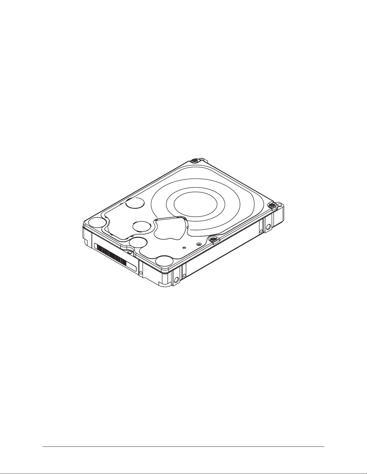
WD Green MB500M-6Gb
Technical Reference Manual
2679-771422-A00 RELEASED 5/2/13 (WD CONFIDENTIAL)
Page 4

RELEASED 5/2/13 (WD CONFIDENTIAL) 2679-771422-A00
Page 5

WD Green MB500M-6Gb Table of Contents
TABLE OF CONTENTS
1. DESCRIPTION AND FEATURES ................................................................................................. 1
1.1 General Description....................................................................................................................................................................... 1
1.2 Product Features ............................................................................................................................................................................ 1
2. SPECIFICATIONS....................................................................................................................... 3
2.1 Performance Specifications ......................................................................................................................................................... 3
2.2 Physical Specifications.................................................................................................................................................................. 4
2.2.1 Physical Dimensions ...................................................................................................................................................... 5
2.3 Mechanical Specifications............................................................................................................................................................ 6
2.4 Electrical Specifications................................................................................................................................................................ 7
2.4.1 Current Requirements and Power Dissipation ........................................................................................................ 7
2.4.2 Input Voltage Requirements......................................................................................................................................... 7
2.4.3 Ripple................................................................................................................................................................................. 7
2.4.4 Power Connectors and Cables................................................................................................................................... 7
2.4.5 ESD.................................................................................................................................................................................... 8
2.5 Environmental Specifications....................................................................................................................................................... 8
2.5.1 Shock and Vibration ....................................................................................................................................................... 8
2.5.2 Temperature and Humidity ........................................................................................................................................... 9
2.5.3 Thermocouple Location................................................................................................................................................. 9
2.5.4 Cooling............................................................................................................................................................................ 10
2.5.5 Atmospheric Pressure .................................................................................................................................................10
2.5.6 Acoustics ........................................................................................................................................................................10
2.5.7 RoHS (Restriction of Hazardous Substances) ......................................................................................................10
2.6 Reliability Specifications .............................................................................................................................................................10
2.7 Agency Approvals.........................................................................................................................................................................11
2.8 Full Model Number Specification.............................................................................................................................................. 11
3. PRODUCT FEATURES.............................................................................................................. 12
3.1 SATA 6 Gb/s................................................................................................................................................................................. 13
3.2 Advanced Format (AF) ................................................................................................................................................................13
3.3 Fluid Dynamic Bearings (FDB)..................................................................................................................................................13
3.4 IntelliPower.....................................................................................................................................................................................13
3.5 Reduced Power Spinup (RPS) ................................................................................................................................................. 13
3.6 Perpendicular Magnetic Recording (PMR).............................................................................................................................14
3.7 System-on-Chip (SOC)..............................................................................................................................................................14
3.8 S.M.A.R.T. Command Transport (SCT)...................................................................................................................................14
3.8.1 Write Same ....................................................................................................................................................................14
3.8.2 Read/Write Long ..........................................................................................................................................................15
3.8.3 Temperature Reporting................................................................................................................................................15
3.9 Reliability Features Set................................................................................................................................................................15
3.9.1 Data Lifeguard™ ............................................................................................................................................................15
3.9.2 Thermal Management ..................................................................................................................................................16
3.9.3 Internal Environmental Protection System ..............................................................................................................16
3.9.4 Recoverable Errors.......................................................................................................................................................16
3.9.5 Unrecoverable Errors ...................................................................................................................................................16
3.9.6 Self Test .......................................................................................................................................................................... 16
3.9.7 ATA Error Logging........................................................................................................................................................16
3.9.8 Defect Management.....................................................................................................................................................17
3.9.9 Automatic Defect Retirement.....................................................................................................................................17
3.9.10 Error Recovery Process...............................................................................................................................................17
3.10 Hot Plug Support..........................................................................................................................................................................17
3.11 Active LED Status ........................................................................................................................................................................18
3.12 Staggered Spinup and Activity Indication (SATA Power Pin 11) .....................................................................................18
3.12.1 Staggered Spinup ........................................................................................................................................................18
3.12.2 Activity Indication ..........................................................................................................................................................18
3.13 CacheFlow™ ..................................................................................................................................................................................18
3.13.1 Write Cache...................................................................................................................................................................19
2679-771422-A00 RELEASED 5/2/13 (WD CONFIDENTIAL) i
Page 6

Table of Contents WD Green MB500M-6Gb
3.13.2 Read Cache ...................................................................................................................................................................19
3.13.3 48-bit Logical Block Addressing (LBA) ..................................................................................................................19
3.14 Power Management .....................................................................................................................................................................20
3.15 Self-Monitoring, Analysis, and Reporting Technology (S.M.A.R.T.)..................................................................................20
3.16 Security Mode ...............................................................................................................................................................................20
3.16.1 Master and User Passwords ......................................................................................................................................20
3.16.2 Security Levels ..............................................................................................................................................................20
4. AT COMMAND SET ................................................................................................................21
4.1 Host Interface Commands .........................................................................................................................................................21
4.1.1 ATA-7/ATA-8 Commands ..........................................................................................................................................21
4.1.2 SATA Commands.........................................................................................................................................................22
4.1.3 Obsolete Commands...................................................................................................................................................22
4.1.4 SCT Commands ...........................................................................................................................................................23
4.2 S.M.A.R.T. (B0h)........................................................................................................................................................................... 23
4.2.1 Read Attribute Values Sub-Command ....................................................................................................................23
4.2.2 Supported Attributes ...................................................................................................................................................25
4.2.3 Read Log Sector...........................................................................................................................................................26
4.3 Identify Device (ECh)...................................................................................................................................................................27
4.4 Set Features (EFh) ......................................................................................................................................................................34
5. INSTALLATION AND SETUP PROCEDURES............................................................................. 35
5.1 Unpacking ......................................................................................................................................................................................35
5.1.1 Handling Precautions...................................................................................................................................................35
5.1.2 Inspection of Shipping Container .............................................................................................................................36
5.1.3 Removal From Shipping Container...........................................................................................................................36
5.1.4 Removal From Static Shielding Bag.........................................................................................................................36
5.1.5 Moving Precautions......................................................................................................................................................36
5.2 Bare Drive Handling External Force ......................................................................................................................................... 37
5.3 Mounting Restrictions..................................................................................................................................................................37
5.3.1 Orientation......................................................................................................................................................................37
5.3.2 Screw Type and Screw Length Limitations............................................................................................................37
5.3.3 Grounding.......................................................................................................................................................................38
5.4 Jumper Settings ............................................................................................................................................................................39
6. MAINTENANCE ........................................................................................................................ 40
7. TECHNICAL SUPPORT............................................................................................................. 41
7.1 WD Online Services ....................................................................................................................................................................41
8. GLOSSARY .............................................................................................................................. 42
ii RELEASED 5/2/13 (WD CONFIDENTIAL) 2679-771422-A00
Page 7

WD Green MB500M-6Gb List of Figures
LIST OF FIGURES
Figure 2-1 Mounting Dimensions...........................................................................................................................................6
Figure 2-2 Drive Base Casting Thermocouple Location ..................................................................................................9
Figure 2-3 Forced Airflow Direction ................................................................................................................................... 10
Figure 5-1 Drive Handling Precautions.............................................................................................................................. 35
Figure 5-2 Hard Drive Removal From Static Shielding Bag ......................................................................................... 36
Figure 5-3 Grounding Diagram ........................................................................................................................................... 38
Figure 5-4 Jumper Settings for WD SATA Hard Drives................................................................................................ 39
2679-771422-A00 RELEASED 5/2/13 (WD CONFIDENTIAL) iii
Page 8

WD Green MB500M-6Gb List of Tables
LIST OF TABLES
Table 2-1 Shock and Vibration ............................................................................................................................................... 8
Table 2-2 Full Model Number Description........................................................................................................................ 11
Table 4-1 ATA-7/ATA-8 Command Opcodes................................................................................................................. 21
Table 4-2 Optional Subcommands ................................................................................................................................... 22
Table 4-3 Obsolete Command Opcodes ......................................................................................................................... 22
Table 4-4 SCT Action Codes .............................................................................................................................................. 23
Table 4-5 Definitions for the 512 Bytes. ........................................................................................................................... 23
Table 4-6 Log Address Definition ....................................................................................................................................... 26
Table 4-7 Identify Device Command.................................................................................................................................. 27
2679-771422-A00 RELEASED 5/2/13 (WD CONFIDENTIAL) iv
Page 9

WD Green MB500M-6Gb Description and Features
1.0 DESCRIPTION AND FEATURES
1.1 General Description
WD Green hard drives are designed for use in systems that require cool and quiet operation, as
secondary drives in PCs, for external enclosures and other applications for which low noise and low
heat are beneficial. These earth-friendly drives are ideal for use whenever energy efficiency is needed.
1.2 Product Features
15 mm Height - 1.5 TB and 2 TB models are 15.0 mm high and are not compatible with
notebook systems. Targeted application is external hard drives.
Serial ATA (SATA) — Serial ATA (SATA) is the next generation bus interface for
2.5-inch hard drives. It is designed to replace Parallel ATA, and has many advantages including
increased transfer rate, improved signal integrity, enhanced data protection, and hot plug support.
Advanced Format (AF) — Technology adopted by WD and other drive manufacturers to
increase media format efficiencies, thus enabling larger drive capacities.
IntelliPower™ — A fine-tuned balance of spin speed, transfer rate and caching algorithms
designed to deliver both significant power savings and solid performance. For each WD Green
drive model, WD may use a different, invariable RPM.
Fluid Dynamic Bearings (FDB) — A bearing design that allows ultra-low rotational drag while
providing high lateral stiffness to steadily hold the spinning center of the diskpack for
high-accuracy of reading and writing of data. FDB provide increased shock robustness and
enhanced reliability while reducing power consumption and acoustics.
Perpendicular Magnetic Recording (PMR) — With PMR technology the magnetization of each
data bit is aligned vertically to the spinning disk, rather than longitudinally as has been the case in
hard drive technology for decades. This enables more data on a given disk than is possible with
conventional longitudinal recording, and provides a platform for future expansion of hard drive
densities.
Reduced Power Spinup (RPS) — WD’s optimized start up feature specifically designed for the
external hard drive and Consumer Electronics (CE) market. Specific focus for RPS is to minimize
the duration and magnitude of the peak power consumption from the hard drive.
System-on-Chip - The System-on-Chip (SOC) is the foundation for WD's next generation
electronics and firmware architecture. The native SATA SOC lowers component count by
integrating a hard disk controller, high performance processor, high speed execution SRAM, and
read channel in a 128-pin package.
S.M.A.R.T. Command Transport (SCT) — The SCT Command Transport feature set provides
a method for a host to send commands and data to a device and for a device to send data and status
to a host using log pages.
Reliability Features Set-Data Lifeguard™ — Representing WD's ongoing commitment to data
protection, Data Lifeguard includes features that enhance the drive’s ability to prevent data loss.
Data Lifeguard data protection utilities include thermal management, an environmental
protection system, and embedded error detection and repair features that automatically detect,
isolate, and repair problem areas that may develop over the extended use of the hard drive. With
these enhanced data reliability features, the drive can perform more accurate monitoring, error
repair, and deliver exceptional data security.
Hot Plug Support — SATA supports hot plugging (also known as “hot swapping”), the ability to
swap out a failed hard drive without having to power down the system or reboot. This capability
contributes to both data availability and serviceability without any associated downtime, making it
a critical feature for extending SATA into enterprise applications.
2679-771422-A00 RELEASED 5/2/13 (WD CONFIDENTIAL) 1
Page 10

Description and Features WD Green MB500M-6Gb
Active LED Status — These drives support external LED requirements. It provides an activity
LED output which is ON during command execution and OFF otherwise.
Staggered Spin-Up — Native SATA feature that allows the system to control whether the drive
will spin up immediately or wait until the interface is fully ready.
CacheFlow™ —WD’s unique, multi-generation caching algorithm evaluates the way data is read
from and written to the drive and adapts “on-the-fly” to the optimum read and write caching
methods. CacheFlow minimizes disk seek operations and overheads due to rotational latency.
CacheFlow supports sequential and random write cache. With write cache and other CacheFlow
features, the user can cache both read and write data. The cache can hold multiple writes and
collectively write them to the hard drive.
48-bit Logical Block Addressing (LBA) — WD SATA drives support both 48-bit and 28-bit
LBA and CHS-based addressing. LBA is included in advanced BIOS and operating system device
drivers and ensures high capacity disk integration.
Power Management — WD SATA drives support the ATA and Serial ATA power management
command set, allowing the host to reduce the power consumption of the drive by issuing a variety
of power management commands.
Automatic Defect Retirement — If the WD SATA drive detects a defective sector while reading,
writing, or performing offline data collection, it automatically relocates the sector without enduser intervention.
Self-Monitoring, Analysis, and Reporting Technology (S.M.A.R.T.) — S.M.A.R.T. enables a
drive’s internal status to be monitored through diagnostic commands at the host level and during
offline activities. S.M.A.R.T. devices employ data analysis algorithms that are used to predict the
likelihood of some near-term degradation or fault conditions. When used with a S.M.A.R.T.
application, the drive can alert the host system of a negative reliability status condition. The host
system can then warn the user of the impending risk of data loss and recommend an appropriate
action.
ATA Security — WD SATA drives support the ATA Security Mode Feature set. The ATA
Security Mode feature set allows the user to create a device lock password that prevents
unauthorized hard disk access even if the drive is removed from the host computer. The correct
password must be supplied to the hard drive in order to access user data. Both the User and
Master Password features are supported, along with the High and Maximum security modes. The
Master Password Revision code is also supported.
2 RELEASED 5/2/13 (WD CONFIDENTIAL) 2679-771422-A00
Page 11

WD Green MB500M-6Gb Specifications
2.0 SPECIFICATIONS
2.1 Performance Specifications
Average Latency 5.8 ms
Rotational Speed IntelliPower
Data Transfer Rates
- Interface Speed
- Internal Transfer Rate
Buffer Size 8 MB
Spindle Start Time
- From Power-on to Drive Ready
- From Power-on to Rotational Speed
Spindle Stop Time 8s average
Load/Unload Cycles
1
During continuous Seek, Read, or Write commands, an algorithm in the code will add latency as required to keep
the VCM motor from overheating. Seek performance will be impacted under this condition.
2
As used for storage capacity, one megabyte (MB) = one million bytes, one gigabyte (GB) = one billion bytes, and
one terabyte (TB) = one trillion bytes. Total accessible capacity varies depending on operating environment. As
used for buffer or cache, one megabyte (MB) = 1,048,576 bytes. As used for transfer rate or interface, megabyte
per second (MB/s) = one million bytes per second, and gigabit per second (Gb/s) = one billion bits per second.
Effective maximum SATA 6 Gb/s transfer rate calculated according to the Serial ATA specification published by
the SATA-IO organization as of the date of this document. Visit www.sata-io.org for details.
3
Defined as the time from power-on to the setting of Drive Ready and Seek Complete including calibration.
4
Defined as the time from power-on to when the full spindle rotational speed is reached.
5
Controlled unload at ambient condition.
1
2
3
4
6 Gb/s
135 MB/s (max)
6.5s average
4.5s average
600,000
2679-771422-A00 RELEASED 5/2/13 (WD CONFIDENTIAL) 3
Page 12
Specifications WD Green MB500M-6Gb
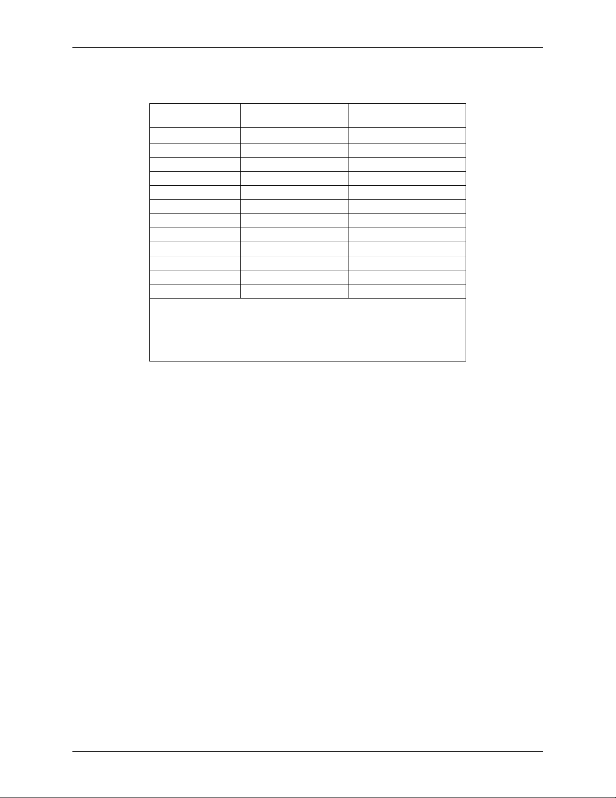
2.2 Physical Specifications
Physical
WD20NPVX WD15NPVX
Specifications
Capacity
Interface SATA 6 Gb/s SATA 6 Gb/s
Actuator Type Rotary Voice Coil Rotary Voice Coil
Number of Disks 4 4
Data Surfaces 8 8
Number of Heads 8 8
Physical Bytes per Sector 4096 4096
Host Bytes per Sector 512 512
User Sectors per Drive 3,907,029,168 2,930,277,168
Servo Type Embedded Embedded
Recording Method Partial DC Target Partial DC Target
ECC LDPC LDPC
1
1
As used for storage capacity, one megabyte (MB) = one million bytes, one gigabyte (GB)
= one billion bytes, and one terabyte (TB) = one trillion bytes. Total accessible capacity
varies depending on operating environment. As used for buffer or cache, one megabyte
(MB) = 1,048,576 bytes. As used for transfer rate or interface, megabyte per second (MB/
s) = one million bytes per second, and gigabit per second (Gb/s) = one billion bits per
second. Effective maximum SATA 6 Gb/s transfer rate calculated according to the Serial
ATA specification published by the SATA-IO organization as of the date of this document.
Visit www.sata-io.org for details.
2,000,398 MB 1,500,301 MB
4 RELEASED 5/2/13 (WD CONFIDENTIAL) 2679-771422-A00
Page 13

WD Green MB500M-6Gb Specifications
2.2.1 Physical Dimensions
English Metric
Dimension Tolerance Dimension Tolerance
Height 0.59 inches
(0.58 inches)
Length 3.94 inches ±0.01 inch 100.20 mm ±0.25 mm
Width 2.75 inches ±0.01 inch 69.85 mm ±0.25 mm
Weight (typical) 0.40 pounds — 182 gm —
Max.
(Min.)
15.00 mm
(14.72 mm)
Max.
(Min.)
2679-771422-A00 RELEASED 5/2/13 (WD CONFIDENTIAL) 5
Page 14
Specifications WD Green MB500M-6Gb
2.3 Mechanical Specifications
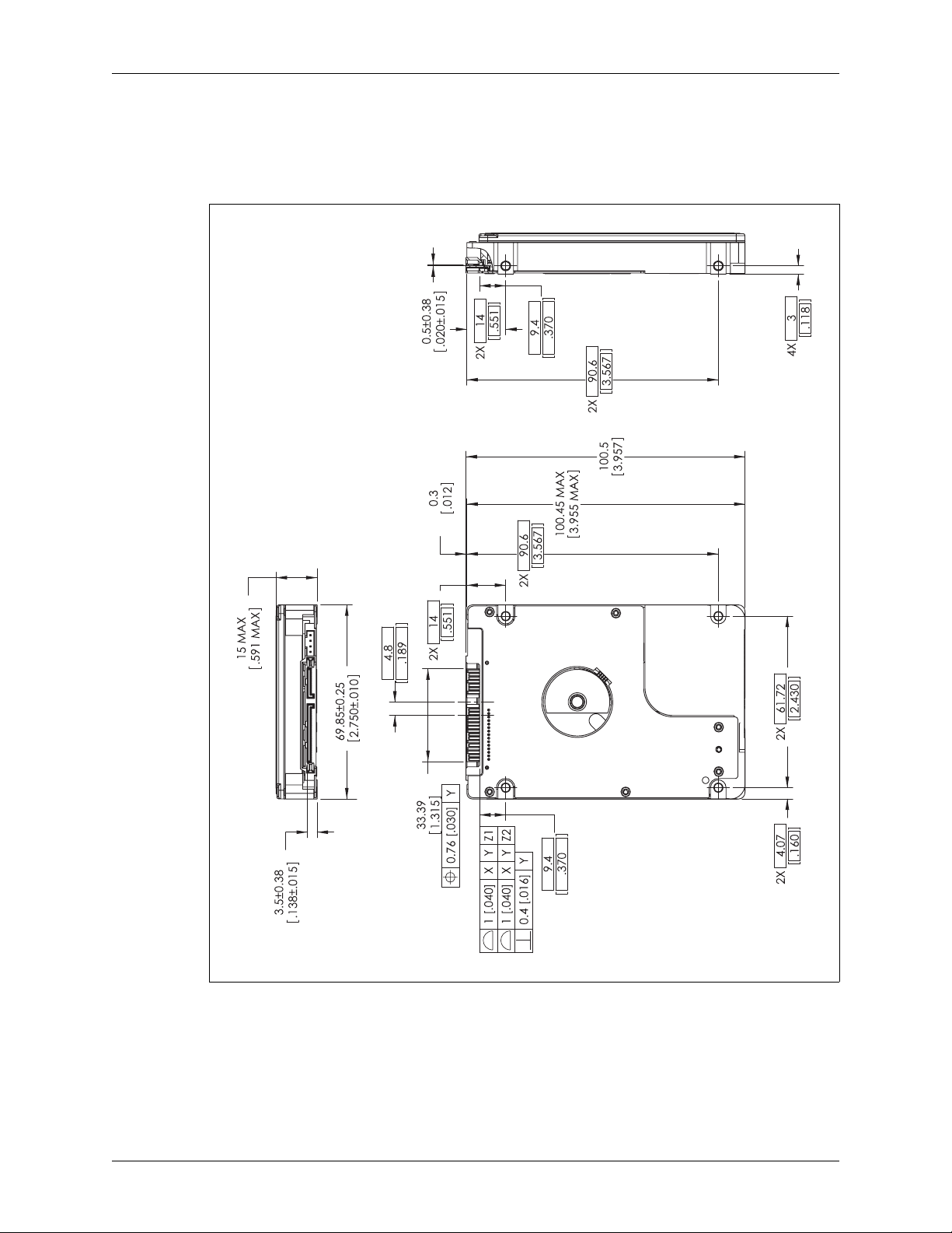
Figure 2-1 shows the mounting dimensions and locations of the screw holes for the drive.
Figure 2-1. Mounting Dimensions
6 RELEASED 5/2/13 (WD CONFIDENTIAL) 2679-771422-A00
Page 15
WD Green MB500M-6Gb Specifications
2.4 Electrical Specifications
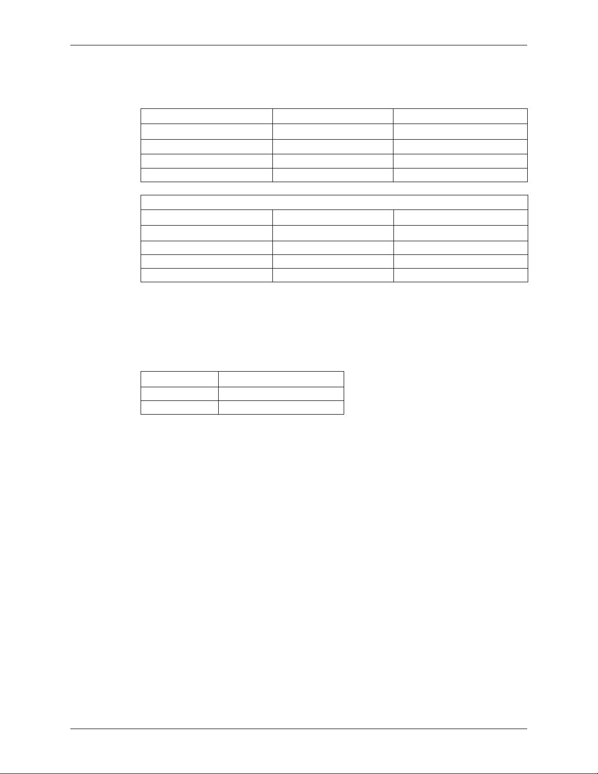
2.4.1 Current Requirements and Power Dissipation
Operating Mode
Current
1
5 VDC
Spinup (max)
Read/Write (average) 340 mA 1.70 W
Seek (average) 400 mA 2.00 W
2
1000 mA 5.00 W
POWER MANAGEMENT COMMANDS
Operating Mode
Current
1
5 VDC
Idle (E1H)(average) 150 mA 0.75W
Standby (E0H)(average) 35 mA 0.18W
Sleep (E6H)(average) 35 mA 0.18W
1
All values are typical (25°C and 5V input) except where specified as maximum.
2
In Reduced Power Spinup (RPS) mode, Spinup (max) = 750 mA.
Power
Power
1
1
2.4.2 Input Voltage Requirements
The input voltage requirement for these drives is +5.0V ± 5%.
2.4.3 Ripple
+5 VDC
Peak-to-peak 100 mV
Frequency 0 - 30 MHz
2.4.4 Power Connectors and Cables
Serial ATA Connectors
For information on SATA data connectors, including the pin definitions of the SATA connectors and
the corresponding signal names and signal functions, refer to the latest SATA specification available for
download at www.sata-io.org.
Cabling Requirements for Serial ATA
The SATA cable consists of four conductors in two differential pairs. The cable may also include drain
wires to be terminated to the ground pins in the SATA cable receptacle connectors. See the SATA
specification for cable specifications. The cable's maximum length is one meter.
2679-771422-A00 RELEASED 5/2/13 (WD CONFIDENTIAL) 7
Page 16
Specifications WD Green MB500M-6Gb
2.4.5 ESD
The ESD specification compliance is determined at room ambient conditions with nominal power
supply settings, unless otherwise specified.
Op-System Level Minimum
Direct contact discharges 8 kV
Direct air discharges 15 kV
Indirect contact discharges (VCP & HCP) 8 kV
Indirect air discharges (VCP & HCP) 15 kV
Non-Op Drive Level
Direct contact discharges 8 kV
Direct air discharges 15 kV
2.5 Environmental Specifications
2.5.1 Shock and Vibration
Table 2-1. Shock and Vibration
Shock
Operating (2 ms) 300G
Non-operating (2 ms) 650G
Note: Half-sine wave, measured without shock isolation and without non-recoverable errors.
Vibration
Operating
Non-operating
1
1.5grms
2
5.8grms
Drive Generated Vibration
Operating (average) 0.25 gm-mm
Rotational Shock Non-Operating
Amplitude 50K rad/sec
Duration 2 ms
1
2
0.00003 g2/Hz (10-500 Hz)
0.06984 g2/Hz (10-500 Hz)
2
Operating Vibration
Drives are tested by applying a random or swept sinusoidal excitation in each linear axis, one axis at a
time. The drive incurs no physical damage and no hard errors while operating and subjected to
continuous vibration not exceeding the level listed in Table 2-1. Operating performance may degrade
during periods of exposure to continuous vibration.
Non-Operating Vibration
Note: This capability applies to handling and transportation of unmounted drives.
Drives are tested by applying a random or swept sinusoidal excitation in each linear axis, one axis at a
time. The drive incurs no physical damage when subjected to continuous vibration not exceeding the
level listed in Table 2-1.
Drive Generated Vibration
Drives are tested by supporting a single drive horizontally in a free-free state and measuring the side-toside vibration. Self vibration may not exceed the level listed in Table 2-1.
8 RELEASED 5/2/13 (WD CONFIDENTIAL) 2679-771422-A00
Page 17
WD Green MB500M-6Gb Specifications
Rotational Shock Non-Operating
Drives are tested by applying a rotational force centered around the actuator pivot. The drive incurs no
physical damage when subjected to the rotational force specified in Table 2-1.
Packaged Shock and Vibration
The shipping packaging is designed to meet the National/International Safe Transit Association
(N/ISTA) standards for packaged products. The drive incurs no physical damage when subjected to the
N/ISTA standards.
2.5.2 Temperature and Humidity
Temperature & Humidity
Operating ambient temperature
Max base casting temperature
Humidity 8-90% RH non-condensing
Thermal Gradient 20°C/hour (maximum)
Humidity Gradient 20%/hour (maximum)
Non-operating Temperature -40°C to 65°C (-40°F to 149°F)
Humidity 5-95% RH non-condensing
Thermal Gradient 30°C/hour (maximum)
Humidity Gradient 20%/hour (maximum)
1
The system environment must allow sufficient air flow to limit maximum surface temperatures as defined.
2
See Figure 2-2.
1
0°C to 60°C (32°F to 140°F)
2
60°C (140°F)
29.4°C (maximum wet bulb)
40°C (maximum wet bulb)
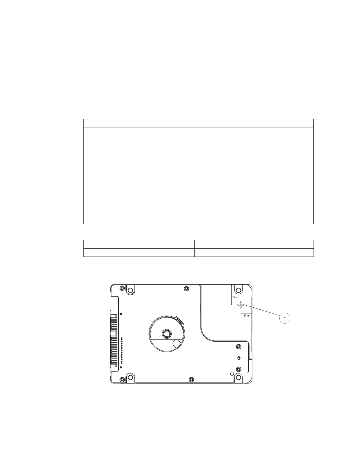
2.5.3 Thermocouple Location
Component Location
Drive base casting #1, Figure 2-2
Figure 2-2. Drive Base Casting Thermocouple Location
2679-771422-A00 RELEASED 5/2/13 (WD CONFIDENTIAL) 9
Page 18
Specifications WD Green MB500M-6Gb
2.5.4 Cooling
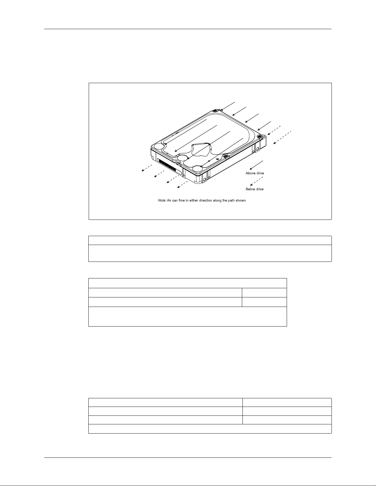
If forced air cooling is required, the drive must be positioned to receive airflow from one or more fans
as indicated in Figure 2-3.
Figure 2-3. Forced Airflow Direction
2.5.5 Atmospheric Pressure
Altitude
Operating -1,000 feet to 10,000 feet (-305m to 3,048m)
Non-operating -1,000 feet to 40,000 feet (-305m to 12,192m)
2.5.6 Acoustics
TYPICAL SOUND POWER LEVEL
Idle Mode (average dBA)
Seek Mode (average dBA)
1
Measured per ECMA-74/ISO 7779.
2
No audible pure tones.
3
Random seek at a rate of 26 seeks per second.
2
3
2.5.7 RoHS (Restriction of Hazardous Substances)
WD hard drive products manufactured and sold worldwide after June 8, 2011, meet or exceed
Restriction of Hazardous Substances (RoHS) compliance requirements as mandated by the RoHS
Directive 2011/65/EU. RoHS aims to protect human health and the environment by restricting the
use of certain hazardous substances in new equipment, and consists of restrictions on lead, mercury,
cadmium, and other substances.
2.6 Reliability Specifications
Component Design Life 5 years
AFR <0.5%
Power on Hours (POH) 3120
1
Ambient temperature 35°C, HDD temperature 40°C.
1
24
25
1
10 RELEASED 5/2/13 (WD CONFIDENTIAL) 2679-771422-A00
Page 19

WD Green MB500M-6Gb Specifications
2.7 Agency Approvals
MB500M-6Gb Regulatory Number (R/N): 771933
These drives meet the standards of the following regulatory agencies:
Federal Communication Commission: Verified to comply with FCC Rules for Radiated and
Conducted Emission, Part 15, Subpart B, for Class B Equipment.
Underwriters Laboratories: Bi-National UL Standard CAN/CSA-C22.2 No. 60950/UL 60950-
1. Standard for Safety of Information Technology Equipment, including Electrical Business
Equipment (File E101559).
TUV NORD CERT GmbH: IEC-950 (EN60950) Standard for Safety of Information
Technology Equipment, including Electrical Business Equipment. EN60065. Standard of Safety
for Audio, Video, and Similar Electronic Apparatus.
CE Compliance for Europe: Verified to comply with EN55022:2006 for RF Emissions and
EN55024:1998, A1:2001 + A2:2003, EN61000-3-2:2000, EN61000-3-3:1995 + A1:2001 for
Generic Immunity as applicable.
C-Tick Compliance for Australia: Verified to comply with AS/NZ3548 for RF Emissions as
required by the Australian Communications Authority.
Korean RRL Mark: Registered as a Class-B product with the South Korean Ministry of
Information and Communication.
Taiwan BSMI EMI Certification: Certified as a Class-B product with the Bureau of Standards
Metrology and Inspection (BSMI).
2.8 Full Model Number Specification
Table 2-2 below provides a summary specification of the model number suffix for this product
platform.
Table 2-2. Full Model Number Description
Model Number Format ID Product Brand RPM Description
WD20NPVX-xxEA4Tx EA4 WD Green IntelliPower MB500M 8 MB SATA 6 Gb/s AF
WD15NPVX-xxEA4Tx EA4 WD Green IntelliPower MB500M 8 MB SATA 6 Gb/s AF
2679-771422-A00 RELEASED 5/2/13 (WD CONFIDENTIAL) 11
Page 20

Product Features WD Green MB500M-6Gb
3.0 PRODUCT FEATURES
SATA 6 Gb/s
Advanced Format (AF)
Fluid Dynamic Bearings (FDB)
IntelliPower
Reduced Power Spinup (RPS)
Perpendicular Magnetic Recording (PMR)
System-on-Chip (SOC)
S.M.A.R.T. Command Transport (SCT)
Reliability Features Set—Data Lifeguard™
Hot Plug Support
Active LED Status
Staggered Spin-Up and Activity Indication (SATA Power Pin 11)
CacheFlow™
48-bit Logical Block Addressing (LBA)
Power Management
Self-Monitoring, Analysis, and Reporting Technology (S.M.A.R.T.)
Security Mode
12 RELEASED 5/2/13 (WD CONFIDENTIAL) 2679-771422-A00
Page 21

WD Green MB500M-6Gb Product Features
3.1 SATA 6 Gb/s
SATA 6 Gb/s is the next generation interface for SATA hard drives. It adds to the functionality of the
SATA 1.5 Gb/s interface with the following features:
Improved Power Management— provides improved power management features including Host
Initiated SATA Power Management (HIPM) and Device Initiated SATA Power Management
(DIPM).
Staggered Spin-up — allows the system to control whether the drive will spin up immediately or
wait until the interface is fully ready before spinning up.
Asynchronous Signal Recovery (ASR) — robustness feature that improves signal recovery.
Enclosure Services — defines external enclosure management and support features.
Backplane Interconnect — defines how to lay out signal line traces in a backplane.
Auto-activate DMA — provides increased command efficiency through automated activation of
the DMA controller.
Device Configuration Overlay (DCO) — allows hiding of supported features via a SATA feature
mask.
3.2 Advanced Format (AF)
Advanced Format (AF) technology is adopted by WD and other drive manufacturers to increase media
format efficiencies, thus enabling larger drive capacities.
In Advanced Format, each physical sector is composed of eight 512 byte logical sectors, totalling 4096
bytes. WD is shipping Advanced Format drives as 512 Byte Emulated Devices until full operating
system support for the Advanced Format host interface is available. 512 Byte Emulated Device drives
are backward compatible with 512 byte sector accesses.
WD Advanced Format hard drives may require you to run the WD Align software utility after you
install your operating system or partition and format the drive as a secondary drive. WD Align
software aligns partitions on the Advanced Format drive to ensure it provides full performance for
certain configurations. Go to www.wdc.com/advformat for important configuration and installation
guidelines.
3.3 Fluid Dynamic Bearings (FDB)
A bearing design that allows ultra-low rotational drag while providing high lateral stiffness to steadily
hold the spinning center of the diskpack for high-accuracy of reading and writing of data. FDB
provide increased shock robustness and enhanced reliability while reducing power consumption and
acoustics.
3.4 IntelliPower
A fine-tuned balance of spin speed, transfer rate and caching algorithms designed to deliver both
significant power savings and solid performance. For each GreenPower™ drive model, WD may use a
different, invariable RPM. Spin speed is reduced but optimized through a special blend of channel
capability, electronics through-put capability, and mechanical resonances to achieve low power
consumption.
3.5 Reduced Power Spinup (RPS)
Applications for 2.5-inch hard drives include USB external hard drives, notebook systems, and
Consumer Electronics (CE). Due to the fact that many of these applications are portable in nature, an
option for limiting startup current levels and increasing spinup speed is necessary.
2679-771422-A00 RELEASED 5/2/13 (WD CONFIDENTIAL) 13
Page 22

Product Features WD Green MB500M-6Gb
To address this requirement, WD has developed Reduced Power Spinup (RPS) mode. RPS-enabled
drives use minimal power consumption during spin up, allowing a greater range of compatibility with
various systems and cables in the marketplace. RPS mode is set via jumper. See Figure 5-4 for more
information.
3.6 Perpendicular Magnetic Recording (PMR)
In perpendicular magnetic recording (PMR), the magnetization of each data bit is aligned vertically to
the spinning disk, rather than longitudinally as has been the case in hard drive technology for decades.
In longitudinal recording, as the bits become smaller and closer together, they experience an increasing
demagnetizing field, much like two bar magnets that are placed end-to-end repel one another. A
property of the media called coercivity must be increased to counteract the demagnetization to keep the
bits stable under thermal fluctuations; otherwise data corruption may occur over time. Higher media
coercivity has pushed the recording head write field to the limit of known materials.
In perpendicular recording, the adjacent bits attract instead of repel (as with bar magnets placed side by
side,) creating more thermally stable bits. In addition, the media contains a magnetically soft
underlayer (SUL) beneath the recording layer. This SUL allows a larger effective write field, thus higher
coercivity media, enabling further increases in density. Lastly, because of the vertical orientation of the
bits, the PMR recording layer tends to be thicker than that used for longitudinal recording, providing
increased signal for the read heads. All of these benefits enable WD engineers to reliably pack more data
on a given disk than is possible with conventional longitudinal recording.
3.7 System-on-Chip (SOC)
The System-on-Chip (SOC) is the foundation for WD's next generation electronics and firmware
architecture. The native SATA SOC lowers component count by integrating a hard disk controller,
high performance processor, high speed execution SRAM, and read channel in a 128-pin package. The
processor has a 5-stage pipeline which can execute instructions in a single cycle and a DSP engine for
enhanced operations. The SOC has on-chip tightly coupled memory for high speed code and data
execution that maximizes the processing bandwidth for timing critical operations. It has a high
performance disk controller that incorporates maximum flexibility, modularity, performance, and low
power consumption. The read/write channel has advanced detection capabilities for high-density
drives.
3.8 S.M.A.R.T. Command Transport (SCT)
The SCT Command Transport feature set provides a method for a host to send commands and data to
a device and for a device to send data and status to a host using log pages. Standard ATA commands
may be interspersed with SCT commands, but SCT commands cannot be nested. SCT commands that
do not require a subsequent data transfer operation are not interspersed with any ATA commands or
each other.
The SCT Command Transport feature set provides a method for a host to send commands and data to
a device and for a device to send data and status to a host using log pages. This capabilitility is used to
pass commands through a driver interface or a bridge where new or unknown commands may be
filtered and not passed to the drive. SCT is also used for issuing commands that require more than 8
parameter bytes. ATA8-ACS provides detailed information on the usage and capabilities of SCT. The
SCT feature set includes the following commands:
Write Same
Read/Write Long
Temperature Reporting
3.8.1 Write Same
The Write Same command allows the host to erase the media, or write a pattern repeatedly across the
media, with a minimum of data transfer from the host. The host can clear the entire media to zeros or
14 RELEASED 5/2/13 (WD CONFIDENTIAL) 2679-771422-A00
Page 23

WD Green MB500M-6Gb Product Features
a specific pattern by sending this command with the pattern as a parameter—no data transfer is
necessary. Write Same can write the entire media, or just a portion of the media. The host can monitor
the progress of the Write Same by issuing SCT Status requests. This frees the host system to do other
tasks while the media is being cleared.
3.8.2 Read/Write Long
The function performed by the Long Sector Access command is based on the obsolete ATA READ
LONG/WRITE LONG capability, and has been extended beyond 28-bit addressing. The Long Sector
data format for both reads and writes is two blocks long (i.e., each block is 512 bytes long). The first
block contains the user data. The second data block contains the error correction and detection bytes.
The remainder of the second block should contain zeros. Once the SCT command has been issued and
the status response indicates that the device is ready to transfer data, log page E1h should be read or
written to transfer the data. Long Sector Access commands cause a forced unit access to occur.
3.8.3 Temperature Reporting
The SCT Temperature Reporting (SCT TR) feature allows a host system to access temperature
information in the drive. This information can been used to control fans or adjust the usage of various
system components to keep the drive within its normal operating temperature. Applications include
Enterprise, Laptop, Desktop and Consumer Electronics. SCT TR reports the maximum and minimum
sustained operating limits, warning level limits, and drive damage limits. In addition to reporting the
limits, SCT TR returns the current drive temperature (a temperature history which the host can use to
predict heating or cooling trends) and the maximum temperature acheived during the lifetime of the
drive as well as the highest temperature achieved since the power was applied to the drive. Detailed
information on this capability can be found in ATA8-ACS.
3.9 Reliability Features Set
3.9.1 Data Lifeguard™
Representing WD's ongoing commitment to data protection, Data Lifeguard includes features that
enhance the drive’s ability to prevent data loss. Data Lifeguard data protection utilities include thermal
management, an environmental protection system, and embedded error detection and repair features
that automatically detect, isolate, and repair problem areas that may develop over the extended use of
the hard drive. With these enhanced data reliability features, the drive can perform more accurate
monitoring, error repair, and deliver exceptional data security.
This self-tuning feature is performed during offline data collection scan. All user sectors on the hard
drive are scanned during times of no activity from the host. Any sector determined to be written poorly
(e.g., off-track), or that is difficult to recover (e.g., because of a developing media defect or thermal
asperity), is marked for repair. Data Lifeguard actively guards your data, even if S.M.A.R.T. operations
are disabled.
All WD drives are defect-free and low-level formatted at the factory. After prolonged use, any drive,
including a WD drive, may develop defects. If you continue receiving data errors in any given file, use
the Data Lifeguard Diagnostics utility to recover, relocate and rewrite the user data to the nearest spare
sector and maintain a secondary defect list.
CAUTION:As with all format utilities, some options in the Data Lifeguard Diagnostics
utility will overwrite user data.
Download the latest versions of the Data Lifeguard Diagnostic and Data Lifeguard Tools programs at
http://support.wd.com.
1
1. Default shipping configuration has Data Lifeguard feature disabled for power management
optimization.
2679-771422-A00 RELEASED 5/2/13 (WD CONFIDENTIAL) 15
Page 24

Product Features WD Green MB500M-6Gb
3.9.2 Thermal Management
The drive is designed with Thermal Management features for high reliability.
State-of-the-art mechanical design—Mechanical design is optimized to reduce the drive’s
temperature. State-of-the-art thermal dissipation and windage design is employed.
Closed loop servo management—Thermal management monitors the drive temperature and can
control servo operations to maintain a stable operating temperature under high temperature
conditions. This is a closed loop servo and thermal control system.
S.M.A.R.T. HDA Temperature Attribute—The S.M.A.R.T. HDA Temperature Attribute is
supported.
Ducted airflow—Provides protection to the Read/Write element from heated air.
3.9.3 Internal Environmental Protection System
This system protects the inside environment of the drive from contamination. System features include:
Filtration System to ensure fast clean-up times
Directed airflow to maximize mechanical cooling
Increase casting surface area to maximize cooling
Ducted air flow to protect read/write elements from heated air
Breather filter located at low pressure area
Enhanced heat dissipation
3.9.4 Recoverable Errors
A sector marked for repair is written back to the same location. The sector is then read several times to
be sure that it was written correctly and that there is no media damage at its location (sector test). If the
sector does not easily and consistently read correctly, the sector is then relocated with original data.
3.9.5 Unrecoverable Errors
If an unrecoverable error is found during the offline scan, the sector is marked. Future reads from this
location will continue to perform full error recovery. However, the next write to this location will
perform a sector test to be sure the media is not damaged, and the sector relocated if the sector test fails.
3.9.6 Self Test
Self Test is a quick way to determine the operation status of a drive. The following Self Tests are
supported:
Quick Test: Completes in less than two minutes.
Extended Test: Tests all the critical subsystems of the drive.
Conveyance Test: Quickly identifies issues caused by handling damage.
Selective Test: Scans host-defined sections of the drive.
The test may be run to completion or be performed as a background task as the drive processes other
commands from the host. The host may then poll the drive for runtime status and test results. Since the
test is embedded in the drive’s firmware, it is always available, requires no installation and can be faster
and more effective than a software-based drive test.
3.9.7 ATA Error Logging
ATA Error Logging provides an industry standard means to record error events and supporting
information that is then accessible by the host. The event record includes the exact command that
caused the failure, the response of the drive, the time of the event and information about the four
commands immediately prior to the errant command. Error Logging can reliably and quickly
16 RELEASED 5/2/13 (WD CONFIDENTIAL) 2679-771422-A00
Page 25

WD Green MB500M-6Gb Product Features
determine whether a system problem is the result of a hard drive failure or other component
malfunction. Error Logging retains total error count for the life of the drive and complete records for
the last five errors.
3.9.8 Defect Management
Every WD drive undergoes factory-level intelligent burn in, which thoroughly tests for and maps out
defective sectors on the media before the drive leaves the manufacturing facility. Following the factory
tests, a primary defect list is created. The list contains the cylinder, head, and sector numbers for all
defects.
Defects managed at the factory are sector slipped. Grown defects that can occur in the field are mapped
out by relocation to spare sectors on the inner cylinders of the drive.
3.9.9 Automatic Defect Retirement
The automatic defect retirement feature automatically maps out defective sectors while reading or
writing. If a defective sector appears, the drive finds a spare sector.
The following item is specific to automatic defect retirement on writes (write auto-relocation):
Data is always written to disk (using automatic defect retirement if required) and no error is
reported.
The following item is specific to automatic defect retirement on reads (read auto-relocation):
When host retries are enabled, the drive will internally flag any unrecoverable errors (DAMNF or
ECC). This flagging allows subsequent write commands to this location to relocate the sector only
if the sector test fails.
3.9.10 Error Recovery Process
The drive has the following means of Error Recovery:
One-the-Fly Recovery: Using LDPC's internal recovery mechanism with Global and Local
Iteration for Error Recovery and Correction. This recovery is real time and does not require any
additional re-reads for the correction.
Simple Firmware Assist Recovery: Single variable re-reads involving off-track recoveries and synch
mark retires.
Extended Firmware Assist Recovery: This retry procedure will step through a combination of
positive/negative track offsets and VGA DAC manipulations to recover the data. In addition,
further retries will also involve Low Pass Filter (FIR) manipulations, Timing recovery, and Synch
Error Recoveries deeper into the retry process. Furthermore, in specific retry steps Hardware assist
is also involved for Extended Retry involving more modification of FIR filters & Erasure Sweep.
LDPC Erasure Sweep Correction: This step sweeps the entire data stream with a Erasure Length
and a Sliding Window, both programmable, to maximize the correction capability.
When an extended retry operation is successful, the controller continues with the command. The
controller clears any changes during the F/W Assist Recovery before commencing to the next
operation.
3.10 Hot Plug Support
SATA supports hot plugging (also known as “hot swapping”), the ability to swap out a failed hard drive
without having to power down the system or reboot. This capability contributes to both data
availability and serviceability without any associated downtime, making it a critical feature for
extending SATA into enterprise applications.
WD SATA drives support hot plugging only in systems where a SATA hard drive storage backplane is
used.
2679-771422-A00 RELEASED 5/2/13 (WD CONFIDENTIAL) 17
Page 26

Product Features WD Green MB500M-6Gb
The Serial ATA revision 2.5 specification requires staggered pins for both the hard drive and drive
receptacles. Staggered pins mate the power signals in the appropriate sequences required for powering
up the hot plugged device. These pins are also specified to handle in excess of the maximum allowed
inrush current that occurs during drive insertion. SATA-compliant devices thus need no further
modification to be hot pluggable and provide the necessary building blocks for a robust hot plug
solution, which typically includes:
Device detection even with power downed receptacles (typical of server applications).
Pre-charging resistors to passively limit inrush current during drive insertion.
Hot plug controllers to actively limit inrush current during drive insertion.
3.11 Active LED Status
The drive supports external LED requirements. It provides an activity LED output which is ON
during command execution and OFF otherwise.
The drive strength of this open Drain Drive Active signal is that it can sink 12mA to 0.4V Max. It is
5V tolerant, meaning that the external LED may be driven from +5V or +3.3V so long as the Host
system provides a series resistor to limit the LED current to the lower of 12mA or the rated operating
current of the LED. As an example with +5V and a 2 volt forward drop across a 10mA LED, a 300
Ohm 5% 1/16W resistor would be suitable. In the case of a 3.3V supply for the same LED, the resistor
would be 130 Ohm 5% 1/16W.
The pin corresponding to P11 shall be used for Active LED.
3.12 Staggered Spinup and Activity Indication (SATA Power Pin 11)
SATA device power connector pin 11 is defined as a means by the host to DISABLE staggered spinup
and it may also be used by the device to provide the host with an activity indication. According to the
SATA II specs, "Staggered Spin-up Disable and Activity Signal shall not be enabled at the same time."
3.12.1 Staggered Spinup
When multiple disks are installed in an enclosure, it is desirable to provide a simple mechanism by
which a subsystem controller can sequence hard drive initialization to minimize the current load
presented during power up. Staggered spinup provides this mechanism by preventing the hard drives
from spinning up until after successful PHY initialization (i.e., after PHY enters DP7:DR_Ready
state).
Staggered spinup is only applicable during initial power-up. If a drive is spun down using ATA
commands—as a result of having been placed in Standby or Sleep power modes, for example—the
drive shall spin up following the rules that govern spinup from low power modes described in ATA/
ATAPI-6 or later.
3.12.2 Activity Indication
The host controller through SATA power pin 11 may access storage device status and activity. The
signal provided by the device for activity indication is a low-voltage low-current signal. It is not suitable
for directly driving an LED. A buffer circuit external to the device must be employed to drive the LED.
The activity signal is based on an open-collector or open-drain active low driver. The device shall
tolerate the activity signal being shorted to ground.
3.13 CacheFlow™
CacheFlow is WD’s unique, multi-generation disk caching system. It incorporates read cache with
write cache.
WD designed CacheFlow to obtain maximum performance with today’s most popular operating
systems and applications. CacheFlow increases performance over prior caching algorithms by
18 RELEASED 5/2/13 (WD CONFIDENTIAL) 2679-771422-A00
Page 27
WD Green MB500M-6Gb Product Features
increasing the number of times that requested data is in the cache. This reduces the number of host
commands that require actual media access thereby improving overall drive performance.
Typical applications perform a variety of access patterns, such as random, sequential, and repetitive.
CacheFlow is designed to dynamically adapt to the changes in access patterns that occur during the
course of application execution.
Random mode is the default operational mode for CacheFlow. Once CacheFlow detects a sequential
access pattern, it leaves random mode. CacheFlow also performs predictive read operations to increase
the probability that data requested in future commands already exists in the cache.
CacheFlow partitions the buffer into multiple segments to allow for the fact that applications may
access multiple non-contiguous areas on the disk. CacheFlow tracks the amount of valid data in each
segment and controls the deallocation of segments to maximize drive performance.
3.13.1 Write Cache
CacheFlow is designed to improve both single and multi-sector write performance by reducing delays
caused by seek time and rotational latency.
The write cache adaptively detects random and sequential access patterns during application execution.
If a defective sector is found during a write cache operation, that sector is automatically relocated before
the write occurs.
3.13.2 Read Cache
CacheFlow implements a multiple segment read cache. Cache segments are assigned to read commands
as they are received from the host.
Each read segment consists of pre and post read sectors in addition to the host-requested sectors. This
maximizes the amount of cache data in the drive’s buffer, thereby increasing the likelihood of cache hits
and improving overall performance.
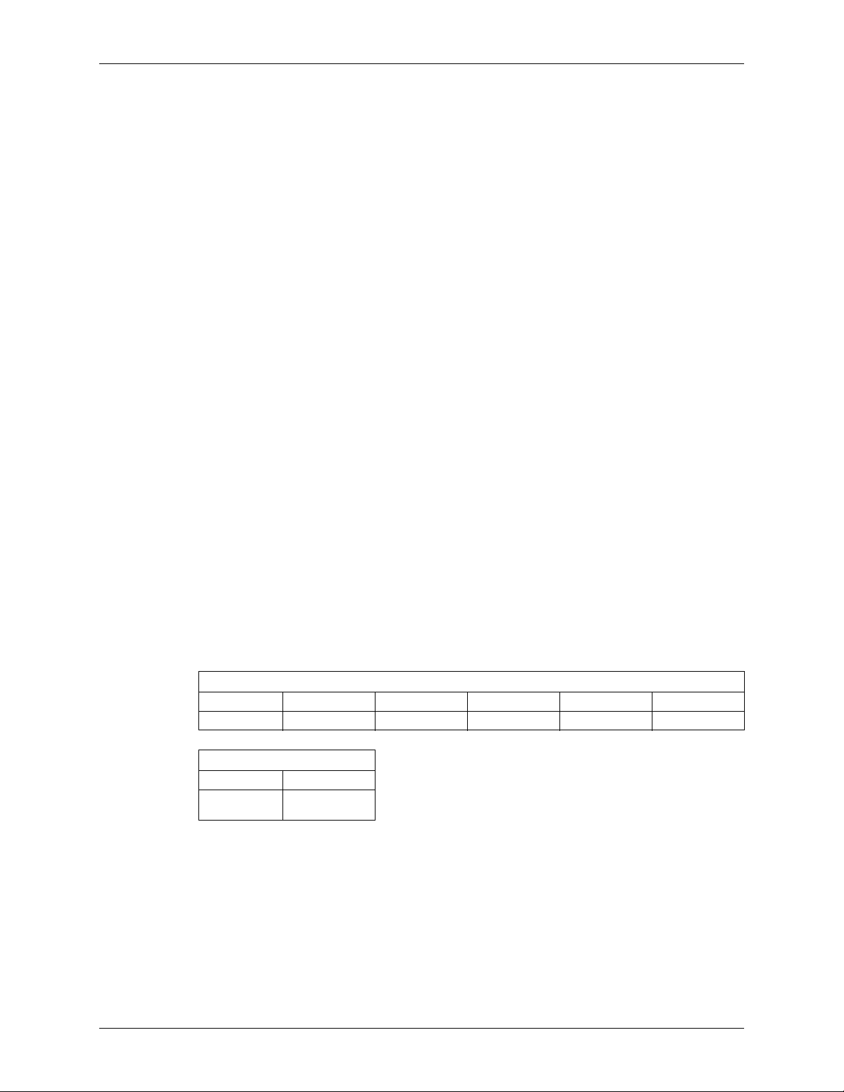
3.13.3 48-bit Logical Block Addressing (LBA)
The 48-bit Address feature set allows devices with capacities up to approximately 281 tera sectors or
approximately 144 peta bytes. In addition, the number of sectors that may be transferred by a single
command are increased by increasing the allowable sector count to 16 bits.
48-bit Address
Bits (47:40) Bits (39:32) Bits (31:24) Bits (23:16) Bits (15:8) Bits (7:0)
LBA High (exp) LBA Mid (exp) LBA Low (exp) LBA High LBA Mid LBA Low
16-bit Sector Count
Bits (15:8) Bits (7:0)
Sector Count
(exp)
Sector Count
2679-771422-A00 RELEASED 5/2/13 (WD CONFIDENTIAL) 19
Page 28

Product Features WD Green MB500M-6Gb
3.14 Power Management
The drives support the ATA power management commands that lower the average power consumption
of the hard drives. For example, to take advantage of the lower power consumption modes of the drive,
an energy efficient host system could implement a power management scheme that issues a Standby
Immediate command when a host resident disk inactivity timer expires. The Standby Immediate
command causes the drive to spin down and enter a low-power mode. Subsequent disk access
commands would cause the drive to spin up and execute the new command.
To avoid excessive wear on the drive due to the starting and stopping of the HDA, set the host’s disk
inactivity timer to no shorter than ten minutes.
The drives also support the SATA power management feature that lowers the average power
consumption of the SATA interface.
3.15 Self-Monitoring, Analysis, and Reporting Technology (S.M.A.R.T.)
S.M.A.R.T. helps you monitor a drive’s internal status through diagnostic commands at the host level.
The drive monitors Read Error Rate, Start/Stop Count, Re-allocated Sector Count, Seek Error Rate,
Power-on Hours Count, Spin-up Retry Count, Drive Calibration Retry Count, Drive Power Cycle
Count, Offline Scan Uncorrectable Sector Count, Ultra ATA CRC Error Rate, Multi-zone Error Rate,
Spin-up Time, Relocation Event Count, and Current Pending Sector Count. The hard drive updates
and stores these attributes in the reserved area of the disk. The drive also stores a set of attribute
thresholds that correspond to the calculated attribute values. Each attribute threshold indicates the
point at which its corresponding attribute value achieves a negative reliability status.
3.16 Security Mode
The Security Mode feature set allows the user to create a device lock password that prevents
unauthorized hard drive access even if the drive is removed from the computer.
3.16.1 Master and User Passwords
The manufacturer/dealer can set a master password using the Security Set Password command, without
enabling the device lock function. The user password should be given or changed by a system user.
Master Password Identifier is supported and set to a default value of 00FE. If a Master Password is set
via a Security Set Password Command, a valid Master Password Revision code value of 0001h – 00FEh
must be used. A Master Password Identifier of 0000h is ignored.
When the master password is set, the drive does not enable the device lock function. When the user
password is set, the drive enables the device lock function, and the drive is locked after the next power
on reset or hard reset.
3.16.2 Security Levels
High - If High level security is set and the user password is forgotten, the master password can be used
to unlock the drive and access the data.
Maximum - If Maximum level security is set and the user password is forgotten, data access is
impossible. Only the master password with a Security Erase Unit command can unlock the drive when
the device lock function is enabled and the user password has been forgotten. When the Security Erase
Unit command is used to unlock the drive, all user data is erased.
20 RELEASED 5/2/13 (WD CONFIDENTIAL) 2679-771422-A00
Page 29

WD Green MB500M-6Gb AT Command Set
4.0 AT COMMAND SET
4.1 Host Interface Commands
4.1.1 ATA-7/ATA-8 Commands
Table 4-1 lists the hexadecimal codes specific to each ATA-7/ATA-8 command supported by these
hard drives. Refer to the D1699 ATA8-ACS specification for full details on each command.
Table 4-1. ATA-7/ATA-8 Command Opcodes
COMMAND HEX OPCODE
CHECK POWER MODE E5
DEVICE CONFIGURATION OVERLAY B1
DOWNLOAD MICROCODE 92
EXECUTE DEVICE DIAGNOSTIC 90
FLUSH CACHE E7
FLUSH CACHE EXT EA
IDENTIFY DEVICE EC
IDLE E3
IDLE IMMEDIATE E1
NOP 00
READ BUFFER E4
READ DMA C8
READ DMA EXT 25
READ FPDMA QUEUED 60
READ LOG EXT 2F
READ LOG DMA EXT 47
READ MULTIPLE C4
READ MULTIPLE EXT 29
READ NATIVE MAX ADDRESS F8
READ NATIVE MAX ADDRESS EXT 27
READ SECTOR(S) 20
READ SECTORS(S) EXT 24
READ VERIFY SECTOR(S) EXT 42
READ VERIFY SECTORS(S) 40
S.M.A.R.T. B0
SECURITY DISABLE PASSWORD F6
SECURITY ERASE PREPARE F3
SECURITY ERASE UNIT F4
SECURITY FREEZE LOCK F5
SECURITY SET PASSWORD F1
SECURITY UNLOCK F2
SET FEATURES EF
SET MAX F9
SET MAX ADDRESS EXT 37
SET MULTIPLE C6
SLEEP E6
STANDBY E2
2679-771422-A00 RELEASED 5/2/13 (WD CONFIDENTIAL) 21
Page 30
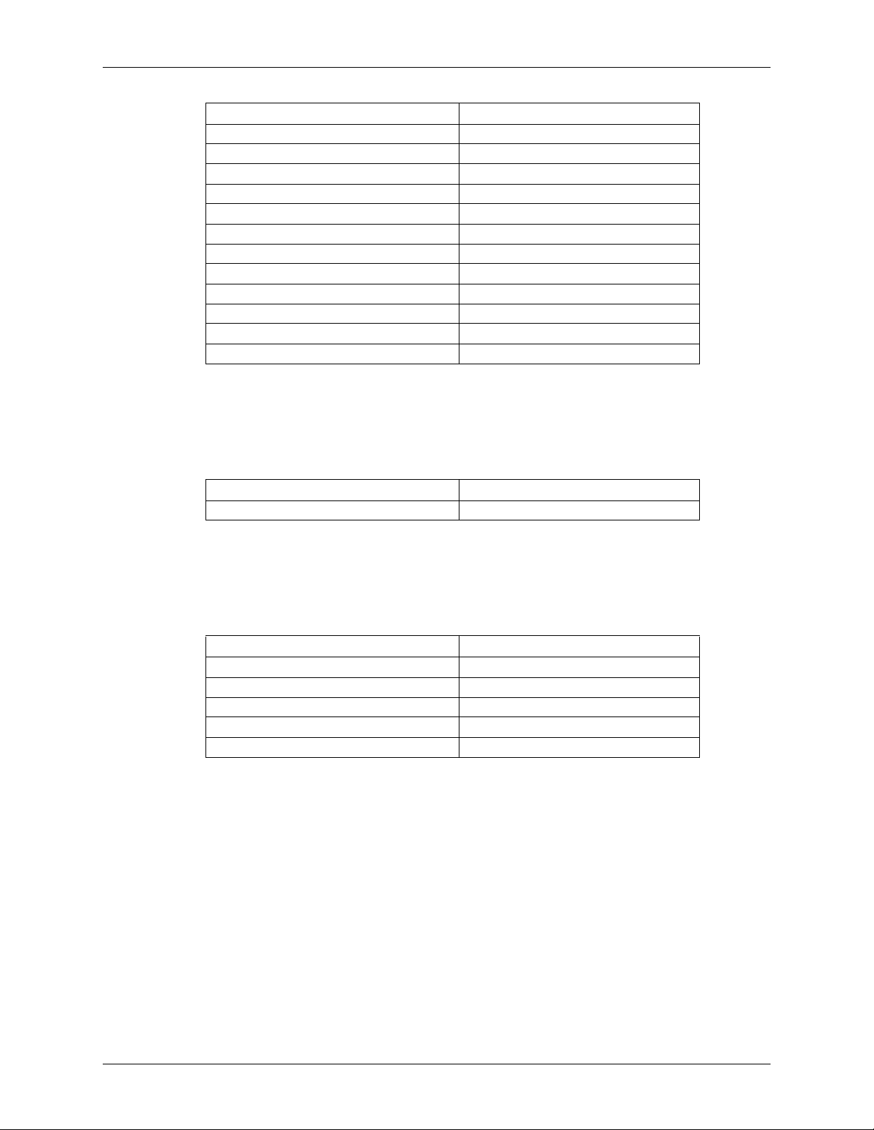
AT Command Set WD Green MB500M-6Gb
COMMAND HEX OPCODE
STANDBY IMMEDIATE E0
WRITE BUFFER E8
WRITE DMA CA
WRITE DMA EXT 35
WRITE FPDMA QUEUED 61
WRITE LOG EXT 3F
WRITE LOG DMA EXT 57
WRITE MULTIPLE C5
WRITE MULTIPLE EXT 39
WRITE SECTOR(S) 30
WRITE SECTOR(S) EXT 34
WRITE UNCORRECTABLE EXT 45
4.1.2 SATA Commands
Table 4-2 lists the hexadecimal codes specific to each SATA command supported by these hard drives.
Refer to the SATA specification for full details on each command.
Table 4-2. Optional Subcommands
COMMAND SUBFUNCTION
DOWNLOAD MICROCODE Mode 3
4.1.3 Obsolete Commands
Table 4-3 lists the hexadecimal codes specific to each obsolete command supported by these hard
drives.
Table 4-3. Obsolete Command Opcodes
COMMAND HEX OPCODE
INITIALIZE DEVICE PARAMETERS 91
READ LONG 22
RECALIBRATE 10
SEEK 70
WRITE LONG 32
22 RELEASED 5/2/13 (WD CONFIDENTIAL) 2679-771422-A00
Page 31
WD Green MB500M-6Gb AT Command Set
4.1.4 SCT Commands
SCT commands provide capabilities not covered in ATA/ATAPI-7 for commands that do not fit the
ATA command delivery model. Some SCT commands report completion when the command begins
execution. Execution progress for these commands may be checked by requesting SCT status. For
instance, the host can track the progress of a Write Same command by issueing a status request once
per minute. See ATA8-ACS for a full description of SCT.
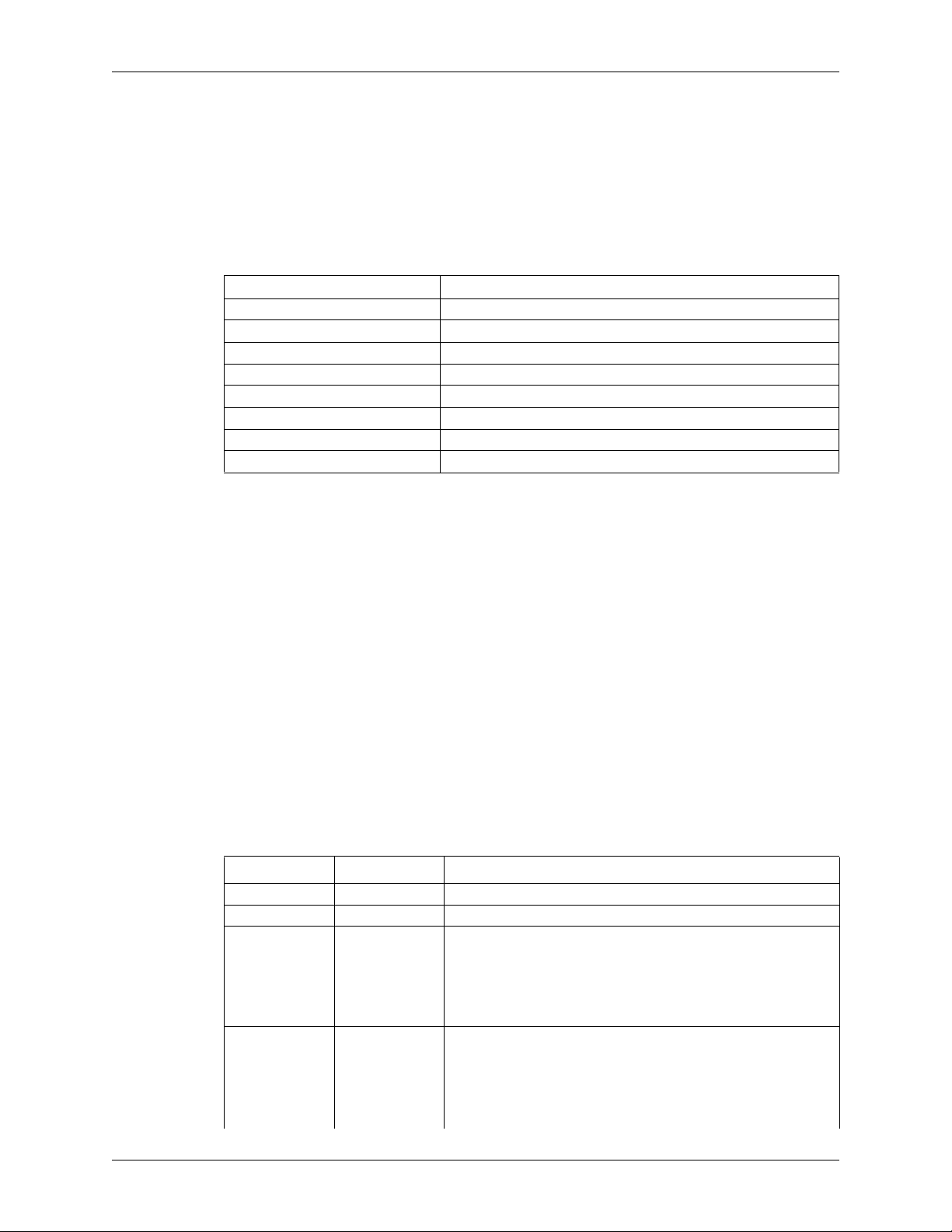
Table 4-4. SCT Action Codes
ACTION CODE DESCRIPTION
0000h RESERVED
0001h Long Sector Access
0002h Write Same
0004h Features Control
0005h SCT Data Tables
0006h Vendor specific
0007h BFFFh Reserved
C000h FFFFh Vendor specific
4.2 S.M.A.R.T. (B0h)
The S.M.A.R.T. command provides access to attribute values, S.M.A.R.T. status, and other
S.M.A.R.T. information. These commands can be used for logging and reporting purposes, and for
accommodating special user needs.
Prior to writing the S.M.A.R.T. command to the Command Register, the host must write key values
into the LBA Mid and LBA High Registers (4Fh, C2h) or the command will be aborted and an error
will be reported.
The S.M.A.R.T. command has several sub-commands that are selectable via the Features Register when
the host issues the S.M.A.R.T. command. To select a sub-command, the host must write the
appropriate sub-command code to the Features Register before issuing the S.M.A.R.T. command. The
sub-commands and their respective codes are listed below. For more detailed information on executing
S.M.A.R.T. commands, please see the ATA specification.
4.2.1 Read Attribute Values Sub-Command
This command returns a sector of data with the drive's S.M.A.R.T. data structure.
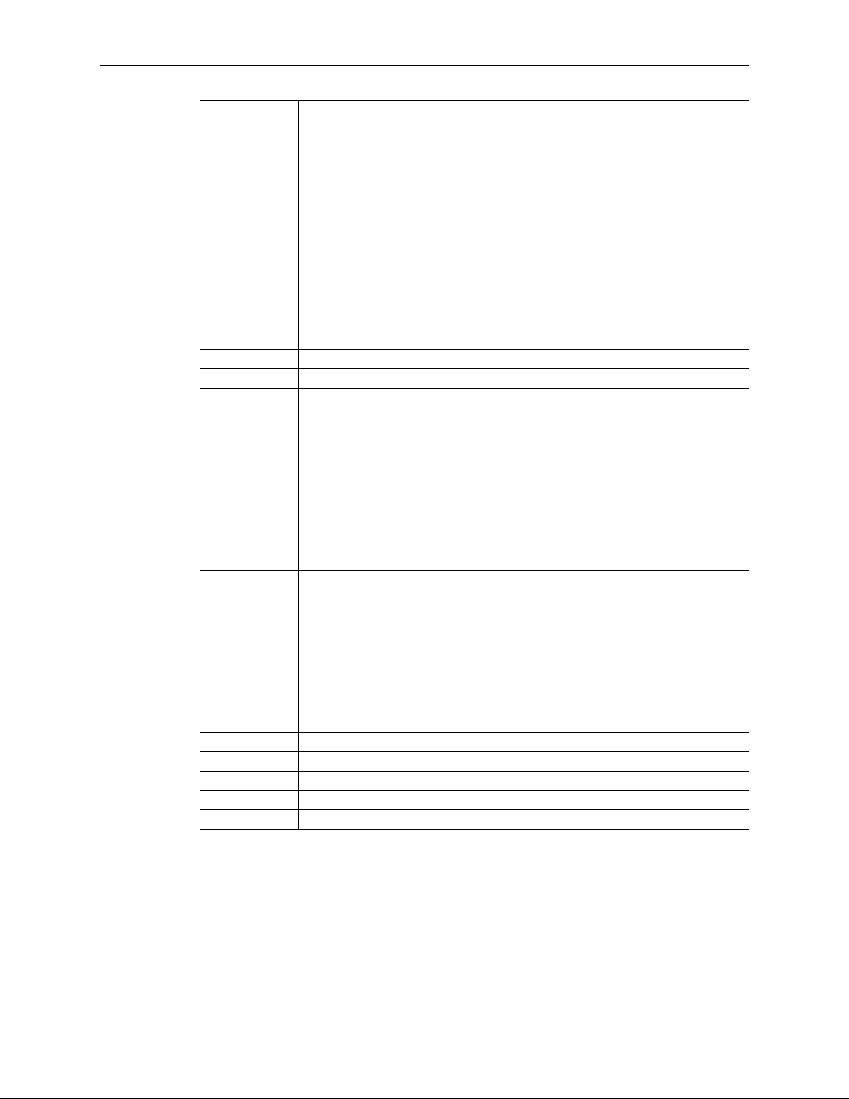
Table 4-5. Definitions for the 512 Bytes.
BYTE VALUE DESCRIPTION
0 - 1 0010h S.M.A.R.T. Data Structure Revision
2 - 361 XX S.M.A.R.T. Attribute Data
Offline data collection status
0Xh OL disabled
362 XX
363 XX Self-Test execution status byte.
8Xh OL enabled
X0h scan not run
X2h scan complete
X4h scan suspended
X5h scan aborted
00h The previous self-test routine completed without error or no
01h The self-test routine was aborted by the host
02h The self-test routine was interrupted by the host with a hard or
self-test has ever been run
soft reset
2679-771422-A00 RELEASED 5/2/13 (WD CONFIDENTIAL) 23
Page 32
AT Command Set WD Green MB500M-6Gb
BYTE VALUE DESCRIPTION
364 - 365 XX
366 XX
367 7Bh
368 - 369 0003h
370 01h
371 XX
372 XX
373 XX
374 XX
375 - 510 XX
511 XX
03h A fatal error or unknown test error occurred while the device
04h The previous self-test completed having a test element that
05h The previous self-test completed having a test element that
06h The previous self-test completed having a test element that
07h The previous self-test completed having a test element that
08h The previous self-test completed having a test element that
090Eh
0Fh Self-test routine in progress
Total time in seconds to complete offline data collection activity
Reserved
Offline data collection capability. Bits are as follows:
S.M.A.R.T. Capability. Bits are as follows:
Error logging capability. Bits are as follows:
Reserved
Short self-test routine completion time in minutes
Extended self-test routine completion time in minutes
Conveyance self-test routine completion time in minutes
Reserved
Checksum
was executing its self-test routine. The device was unable to
complete the self-test routine.
failed. The test element that failed is not known.
failed. The electrical element of the test failed.
failed. The servo (and/or seek) test element of the test failed.
failed. The read element of the test failed.
failed. The element damage is suspected to be caused by
handling.
Reserved
1 = Offline Immediate Command supported
0
1 = Auto Offline enable\disable command supported
1
0 = Offline will suspend on and will resume after host
2
command
1 = Offline read scan implemented
3
1 = DST Short and Extended tests supported
4
1 = DST Conveyance test supported
5
1 = DST Selective test supported
6
0 = Reserved
7
1 = The device saves SMART data prior to going into a power
1
saving mode
1 = Device complies with SMART data autosave after an event
1
Reserved
2-15
1 = Error logging supported
0
Reserved
1
24 RELEASED 5/2/13 (WD CONFIDENTIAL) 2679-771422-A00
Page 33
WD Green MB500M-6Gb AT Command Set
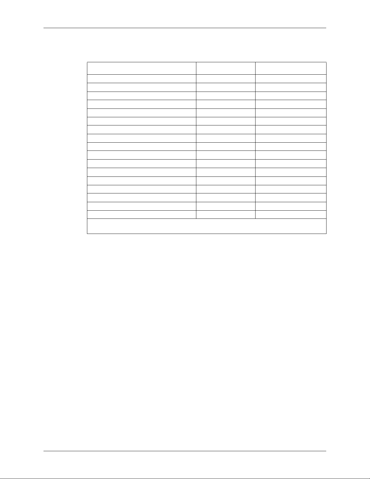
4.2.2 Supported Attributes
The drive supports the following attributes.
Attribute Attribute ID Number Pre-Failure/Advisory Bit
Read Error Rate 1 Pre-Failure
Spin-up Time 3 Pre-Failure
Start/Stop Count 4 Advisory
Re-allocated Sector Count 5 Pre-Failure
Seek Error Rate 7 Advisory
Power-on Hours Count 9 Advisory
Spin-up Retry Count 10 Advisory
Drive Calibration Retry Count 11 Advisory
Drive Power Cycle Count 12 Advisory
Emergency Retract Cycles 192 Advisory
Load/Unload Cycles 193 Advisory
HDA Temperature
Relocation Event Count 196 Advisory
Current Pending Sector Count 197 Advisory
Offline Scan Uncorrectable Sector Count 198 Advisory
Ultra DMA CRC Error Rate 199 Advisory
Multi-zone Error Rate 200 Advisory
1
Status bits are typical but may vary.
2
See “Temperature Reporting” on page 15 for a better mechanism.
2
194 Advisory
(Status Flags bit 0)
1
Attributes that use the Pre-Failure/Advisory Bit Set can predict potential future degrading or faulty
conditions. Attributes with the Failure/Advisory Bit Clear are used for informational purposes only,
they do not indicate impending drive failure.
The S.M.A.R.T. data saving process is a background task. After a pre-determined idle period, the selfmonitoring data is automatically saved to the disk.
2679-771422-A00 RELEASED 5/2/13 (WD CONFIDENTIAL) 25
Page 34
AT Command Set WD Green MB500M-6Gb
4.2.3 Read Log Sector
There are several logs that can be read with the S.M.A.R.T. Read Log Sector sub-command. The LBA
Low Register indicates the log sector to be returned.
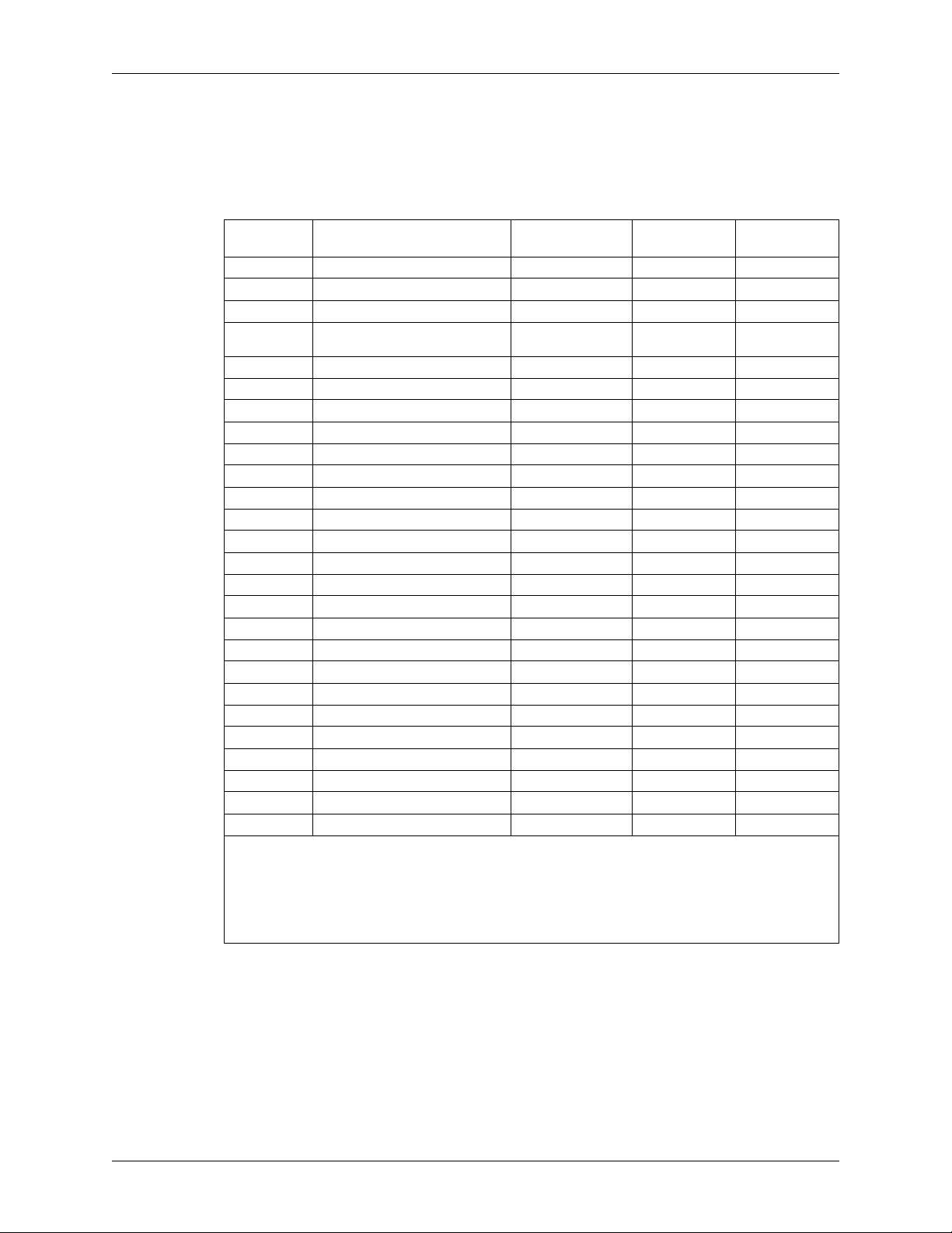
Table 4-6. Log Address Definition
Log
Log Name Feature Set R/W Access
Address
00h Log directory ExtLog RO GPL, SL
01h Summary Log SMART RO SL
02h Comprehensive SMART error log SMART RO SL
03h
04h Device Statistics N/A RO GPL, SL
05h Reserved Reserved Reserved
06h SMART self-test log SMART RO SL
07h Extended SMART self-test log ExtLog RO GPL
08h Reserved Reserved Reserved
09H Selective self-test log SMART R/W SL
0Ah-0Fh Reserved N/A Reserved
10h NCQ Command Error NCQ RO GPL
11h SATA PHY Counters ExtLog RO GPL
12h-17h Reserved for Serial ATA N/A Reserved
18h-1Fh Reserved N/A Reserved
20h Obsolete
21h Write Stream Error Log Streaming RO GPL
22h Read Stream Error Log Streaming RO GPL
23h Obsolete
24h-7Fh Reserved N/A Reserved
80h-9Fh Host vendor specific SMART / ExtLog R/W GPL, SL
A0h-BFh Device vendor specific SMART / ExtLog VS GPL, SL
C0h-EFh Reserved Reserved Reserved
E0h SCT Command/Status N/A R/W GPL, SL
E1h SCT Data Transfer GPL, SL
E2h-FFh Reserved Reserved Reserved
RO – Read Only
R/W – Read / Write
SMART – Supported by B0h command code.
ExtLog – Supported by 2Fh/3Fh command code.
VS – Vendor Specific
SCT – SMART Command Transport
Extended Comprehensive SMART
error log
ExtLog RO GPL
26 RELEASED 5/2/13 (WD CONFIDENTIAL) 2679-771422-A00
Page 35
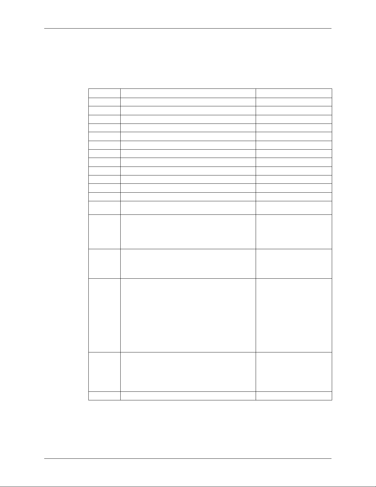
WD Green MB500M-6Gb AT Command Set
4.3 Identify Device (ECh)
The Identify Device command transfers 512 bytes of data that specify the drive’s parameters. Table 4-7
lists the parameters read by the host.
Table 4-7. Identify Device Command
WORD FIELD DESCRIPTION VALUE
0 General Configuration 427Ah
1Obsolete XXXX
2 Specific Configuration XXXX
3Obsolete XXXX
4-5 Retired 0
6Obsolete XXXX
7-8 Reserved for assignment by the CompactFlash™ Association 0
9 Retired 0
10-19 Serial Number (ATA String) WDnnnnnnnn
20-21 Retired XXXX
22 Obsolete 0
23-26 Firmware Revision (ATA String) nnnn
27-46 Model Numbers (ATA String) “WDC WD20NPVX-nnnnnnn”
47 READ/WRITE MULTIPLE support
Bit 15-8: 80h
Bit 7-0: 00h: Reserved
01h-FFh = Maximum number of logical sectors that shall be
transferred per DRQ data block on READ/WRITE
MULTIPLE commands
48 Trusted Computing feature set options
49 Capabilities
50 Capabilities
51-52 Obsolete 0
Bit 15: Shall be cleared to zero
Bit 14: Shall be set to one
Bit 13-1: Reserved for the Trusted Computing Group
Bit 0: If set, Trusted Computing feature set is supported
Bit 15-14: Reserved for the IDENTIFY PACKET DEVICE
command.
Bit 13: If set, Standby timer values as specified in this
standard are supported.
0 = Standby timer values shall be managed by the device
Bit 12: Reserved for the IDENTIFY PACKET DEVICE
command
Bit 11: If set, IORDY supported
Bit 10: If set, IORDY may be disabled
Bit 9: If set, LBA supported
Bit 8: If set, DMA supported
Bit 7-2: Reserved
Bit 1: Current Long Physical Alignment Setting
Bit 15: Shall be cleared to zero.
Bit 14: Shall be set to one.
Bit 13-2: Reserved.
Bit 1: Obsolete
Bit 0: Shall be set to one to indicate a device specific
Standby timer value minimum
“WDC WD15NPVX-nnnnnnn”
8010h
4000h
2F00h
4001h
2679-771422-A00 RELEASED 5/2/13 (WD CONFIDENTIAL) 27
Page 36
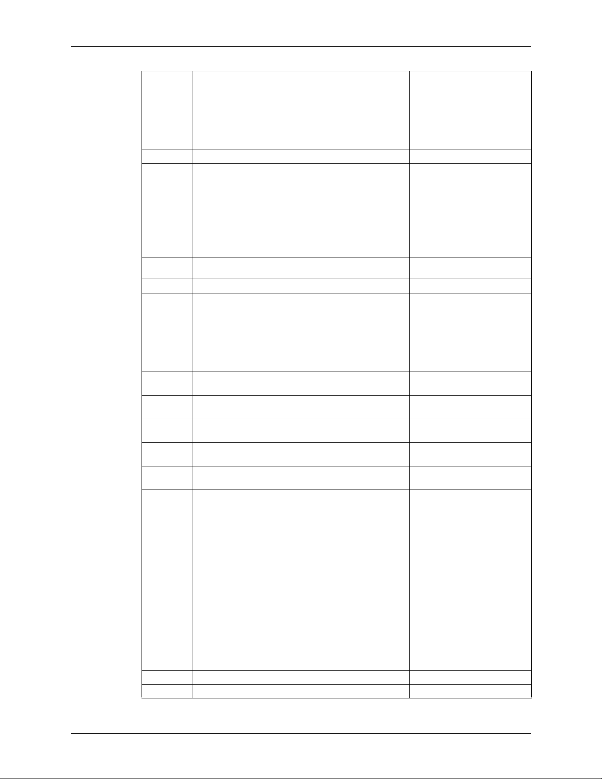
AT Command Set WD Green MB500M-6Gb
53 Additional Words Valid
Bit 8-15: Free-fall Control Sensitivity
00h = Vendor’s recommended setting
01h-FFh = Sensitivity level. A larger number is a
more sensitive setting.
Bit 7-3: Reserved
Bit 2: If set, the fields reported in word 88 are valid
Bit 1: If set, the fields reported in words 70-64 are valid
Bit 0: Obsolete
54-58 Obsolete XXXX
59 Current Blocking Factor
Bit 15: 1=The BLOCK ERASE EXT command is supported
Bit 14: 1= The OVERWRITE EXT command is supported
Bit 13: 1=The CRYPTO Scramble EXT command is
supported
Bit 12: 1=The Sanitize feature set is supported
Bit 9-11 Reserved
Bit 8: 1=Multiple local sector setting is valid
Bit 0-7: Current setting for number of logical sectors that
shall be transferred per DRQ data block on READ/WRITE
Multiple commands
60-61 Total number of user addressable logical sectors for 28 bit
62 Obsolete 0
63 Multi-Word DMA Transfer Mode Supported
64 Advanced PIO Modes Supported
65 Min. Multi-Word DMA Transfer Cycle Time (ns)
66 Manufacturer Recommended Multi-Word DMA Cycle Time
67 Min. PIO Transfer Cycle Time without flow control
68 Min. PIO Transfer Cycle Time with IORDY flow control
69 Additional Supported
70 Reserved 0
71-74 Reserved for the Identify Packet Device command 0
commands (DWord)
Bit 15-11: Reserved
Bit 10: If set, Multiword DMA mode 2 is selected
Bit 9: If set, Multiword DMA mode 1 is selected
Bit 8: If set, Multiword DMA mode 0 is selected
Bit 7-3: Reserved
Bit 2: If set, Multiword DMA mode 2
Bit 1: If set, Multiword DMA mode 1
Bit 0: If set, Multiword DMA mode 0
Bits 0-7: PIO Modes supported
Bit 15-0: Cycle time in nanoseconds
Bit 15-0: Cycle time in nanoseconds
Bit 15-0: Cycle time in nanoseconds
Bit 15-0: Cycle time in nanoseconds
Bit 15: If set, CFast Specification Support
Bit 14: If set, Deterministic data in trimmed LBA range(s) is
supported
Bit 13: If set, Long Physical Sector Alignment Error
Reporting Control is supported
Bit 12: If set, DEVICE CONFIGURATION IDENTIFY DMA
and DEVICE CONFIGURATION SET DMA are supported
Bit 11: If set, READ BUFFER DMA is supported
Bit 10: If set, WRITE BUFFER DMA is supported
Bit 9: If set, SET MAX SET PASSWORD DMA and SET
MAX UNLOCK DMA are supported
Bit 8: If set, DOWNLOAD MICROC
Bit 6: If set, Optional ATA device 28-bit commands
supportedODE DMA is supported
Bit 7: If set, Reserved for IEEE 1667
Bit 5: If set, Trimmed LBA range(s) returning zeroed data is
supported
Bit 4: If set, Device Encrypts All User Data
Bit 3: If set, Extended Number of User Addressable Sectors
is supported
Bit 2-0: Reserved
0007h
XXh
0FFFFFFFh
XX07h
0003h
120
120
120
120
0
28 RELEASED 5/2/13 (WD CONFIDENTIAL) 2679-771422-A00
Page 37

WD Green MB500M-6Gb AT Command Set
75 Queue Depth
Bit 15-5: Reserved
Bit 4-0: Maximum queue depth - 1
76 Serial ATA Capabilities
77 Serial ATA Additional Capabilities
78 Serial ATA Features Supported
79 Serial ATA Features Enabled
80 Major Version Number
81 Minor Version Number 0000h
Bit 15: If set, Supports Read Log DMA Ext
Bit 14: If set, Supports Device Automatic Partial to Slumber
transitions
Bit 13: If set, Supports Host Automatic Partial to Slumber
transitions
Bit 12: Supports Native Command Queuing priority
information
Bit 11: Supports Unload while NCQ commands
outstanding
Bit 10: Supports Phy event counters
Bit 9: Supports receipt of host-initiated interface power
management requests
Bit 8: Supports Native Command Queuing (NCQ)
Bit 7-3: Reserved for future Serial ATA signaling speed
grades
Bit 2: 1= Supports Serial ATA Gen2 signaling speed
(3 Gb/s)
Bit 1: 1= Supports Serial ATA Gen1 signaling speed
(1.5 Gb/s)
Bit 0: Shall be cleared to zero
Bit 15 - 7: Reserved
Bit 6: If set, Supports Receive and Send FPDMA Queued
Commands
Bit 5: If set, Supports NCQ Queue Management Command
Bit 4: If set, Supports NCQ Streaming
Bit 3 - 1: Coded value indicating negotiated Serial ATA
signal Speed
Bit 0: Shall be cleared to zero
Bit 15-8: Reserved for Serial ATA
Bit 7: If set, device supports NCQ Autosense
Bit 6: If set, device supports software settings preservation
Bit 5: Reserved for Serial ATA
Bit 4: If set, device supports in-order data delivery
Bit 3: If set, device supports initiating power management
Bit 2: If set, device supports DMA Setup Auto-activation
Bit 1: If set, device supports non-zero buffer offsets
Bit 0: Cleared to zero
Bits 15-7: Reserved for Serial ATA
Bit 6: If set, software settings preservation enabled
Bit 5: Reserved for Serial ATA
Bit 4: If set, In-order data delivery enabled
Bit 3: If set, device initiated power management enabled
Bit 2: If set, DMA Setup Auto-activation enabled
Bit 1: If set, non-zero buffer offsets enabled
Bit 0: Cleared to zero
Bit 15-10: Reserved
Bit 9: if set, supports ACS-2
Bit 8: if set, supports ATA8-ACS
Bit 7: if set, supports ATA/ATAPI-7
Bit 6: if set, supports ATA/ATAPI-6
Bit 5: if set, supports ATA/ATAPI-5
Bit 4 –1: Obsolete
Bit 0: Reserved
1111 1111 0000 0110b
0000 0000 0100 1100b
0000 0000 0X00 XX00b
001Fh
FF06h
000Xh
004Ch
03FEh
2679-771422-A00 RELEASED 5/2/13 (WD CONFIDENTIAL) 29
Page 38

AT Command Set WD Green MB500M-6Gb
82 Command and feature sets supported
Bit 14: If set, NOP command supported
Bit 13: If set, Read buffer command supported
Bit 12: If set, Write buffer command supported
Bit 11: Obsolete
Bit 10: If set, Host Protected Area Feature Set supported
Bit 9: If set, Device Reset command supported
Bit 8: If set, Service interrupt supported
Bit 7: If set, Release interrupt supported
Bit 6: If set, look-ahead supported
Bit 5: If set, Write Cache supported
Bit 4: Cleared to 0 to indicate that the PACKET feature set
is not supported.
Bit 3: If set, mandatory Power Management Feature Set
supported
Bit 2: Obsolete
Bit 1: If set, Security Feature Set supported
Bit 0: If set, SMART Feature Set supported
83 Command Set Supported
84 Command and feature sets supported
85 Command and feature sets supported or enabled
Bit 15: Shall be cleared to 0
Bit 14: Shall be set to 1
Bit 13: If set, Flush Cache EXT command supported
Bit 12: If set, mandatory Flush Cache command supported
Bit 11: If set, DCO feature set supported
Bit 10: If set, 48-bit Address Feature Set supported
Bit 9: Not supported
Bit 8: If set, Set Max Security Extension supported
Bit 7: Reserved
Bit 6: If set, Set Features subcommand required to spin-up
after power-up
Bit 5: If set, Power-Up In Standby feature set supported
Bit 4: Obsolete
Bit 3: If set, Advanced Power Management feature set
supported
Bit 2: If set, CFA feature set supported
Bit 1: If set, Read/Write DMA Queued supported
Bit 0: If set, Download Microcode command supported
Bit 15: Shall be cleared to zero
Bit 14: Shall be set to one
Bit 13: If set, Idle Immediate with Unload Feature supported
Bit 12: Reserved
Bit 11: Reserved
Bit 9-10: Obsolete
Bit 8: If set, 64-bit World wide name supported
Bit 7: If set, Write DMA Queued FUA EXT command
supported
Bit 6: If set, Write DMA FUA EXT and Write Multiple FUA
EXT commands supported
Bit 5: If set, General Purpose Logging feature set supported
Bit 4: If set, Streaming Feature Set supported
Bit 3: Obsolete
Bit 2: If set, Media serial number supported
Bit 1: If set, SMART Self-Test supported
Bit 0: If set, SMART Error Logging supported
Bit 15: Obsolete
Bit 14: If set, NOP command supported
Bit 13: If set, Read Buffer command supported
Bit 12: If set, Write Buffer command supported
Bit 11: Obsolete
Bit 10: If set, Host Protected Area has been established
Bit 9: If set, DEVICE RESET command supported
Bit 8: If set, SERVICE interrupt enabled
Bit 7: If set, Release Interrupt enabled
Bit 6: If set, Read look-ahead enabled
Bit 5: If set, Volatile Write cache enabled
Bit 4: Cleared to 0 to indicate that the PACKET feature set
is not supported
Bit 3: Set to 1 to indicate that the Mandatory Power
Management feature set is supported
Bit 2: Obsolete
Bit 1: If set, Security Feature Set enabled
Bit 0: If set, SMART Feature Set enabled
0111 0100 0110 1011b
746Bh
0111 1101 0110 1001b
7D69h
0110 0001 0010 0011b
6123h
0111 0X0X XXX0 10XXb
30 RELEASED 5/2/13 (WD CONFIDENTIAL) 2679-771422-A00
Page 39

WD Green MB500M-6Gb AT Command Set
86 Commands and feature sets supported or enabled
Bit 15: If set, Words 119-120 are valid
Bit 14: Reserved
Bit 13: If set, Flush Cache EXT command supported
Bit 12: If set, Flush Cache command supported
Bit 11: If set, Device Configuration Overlay supported
Bit 10: If set, 48-bit Address Feature Set supported
Bit 9: Not supported
Bit 8: If set, Set Max Security Extension enabled by Set Max
Set Password
Bit 7: Reserved
Bit 6: If set, Set Features subcommand required to spin-up
after power-up
Bit 5: If set, Power-Up In Standby feature set enabled
Bit 4: Obsolete
Bit 3: If set, Advanced Power Management feature set
enabled
Bit 2: If set, CFA Feature Set enabled
Bit 1: If set, Read/Write DMA Queued command supported
Bit 0: If set, Download Microcode command supported
87 Commands and feature sets supported or enabled
Bit 15: Shall be cleared to zero
Bit 14: Shall be set to 1
Bit 13: If set, Idle Immediate with Unload Feature supported
Bit 12: Reserved
Bit 11: Reserved
Bit 9-10: Obsolete
Bit 8: If set, 64-bit World wide name supported
Bit 7: If set, Write DMA Queued FUA EXT command
supported
Bit 6: If set, Write DMA FUA EXT and Write Multiple FUA
EXT commands supported
Bit 5: If set, General Purpose Logging Feature Set
supported
Bit 4: Obsolete
Bit 3: If set, Media Card Pass Through Command feature
set supported
Bit 2: If set, Media serial number is valid
Bit 1: If set, SMART Self-Test supported
Bit 0: If set, SMART Error Logging supported
88 Ultra DMA modes
89 Bit 15-8: Reserved
90 Bit 15-8: Reserved
91 Current APM level value XXXXh
92 Master Password Identifier XXXXh
93 Hardware reset result 0
94 Obsolete 0
95 Stream Minimum Request Size 0
96 Stream Transfer Time - DMA 0
97 Stream Access Latency -DMA and PIO 0
98-99 Stream Performance Granularity (Dword) 0
Bit 15: Reserved
Bit 14: If set, Ultra DMA Mode 6 is selected
Bit 13: If set, Ultra DMA Mode 5 is selected
Bit 12: If set, Ultra DMA Mode 4 is selected
Bit 11: If set, Ultra DMA Mode 3 is selected
Bit 10: If set, Ultra DMA Mode 2 is selected
Bit 9: If set, Ultra DMA Mode 1 is selected
Bit 8: If set, Ultra DMA Mode 0 is selected
Bit 7: Reserved
Bit 6: Ultra DMA mode 6 supported
Bit 5: Ultra DMA mode 5 supported
Bit 4: Ultra DMA mode 4 supported
Bit 3: Ultra DMA mode 3 supported
Bit 2: Ultra DMA mode 2 supported
Bit 1: Ultra DMA mode 1 supported
Bit 0: Ultra DMA mode 0 supported
Bit 7-0: Time required for Normal Erase mode SECURITY
ERASE UNIT command
Bit 7-0: Time required for Normal Erase mode SECURITY
ERASE UNIT command
1011 11XX 01X0 X001b
0110 0001 0010 0011b
6123h
XXXX XXXX 0111 1111b
XX7Fh
BDh (2 TB)
BDh (2 TB)
2679-771422-A00 RELEASED 5/2/13 (WD CONFIDENTIAL) 31
Page 40
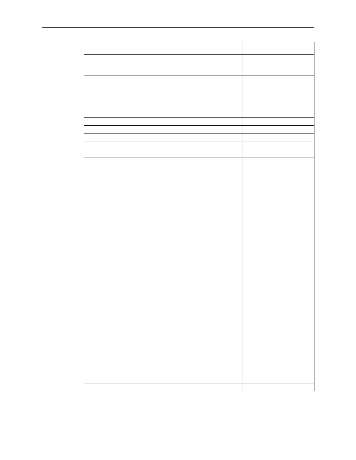
AT Command Set WD Green MB500M-6Gb
100-103 Total number of User Addressable Logical Sectors (QWord) WD20NPVT (3,907,029,168)
104 Streaming Transfer Time - PIO 0
105 Maximum number of 512 byte blocks per Data Set
106 Physical sector size / logical sector size
107 Inter-seek delay for ISO 7779 standard acoustic testing 0
108-111 World Wide Name XXXXXXXXXXXXXXXX
112-115 Reserved 0
116 Reserved for TLC 0
117-118 Logical Sector size (DWord) 0
119 Commands and feature sets supported (Continued from words
120 Commands and feature sets supported (Continued from words
121-126 Reserved 0
127 Obsolete 0
128 Security Status
129-159 Vendor Specific 0
Management command
Bit 15 Shall be cleared to zero
Bit 14 Shall be set to one
Bit 13 if set, Device has multiple logical sectors per physical sector.
Bit 12 if set, Device Logical Sector longer than 256 Words
Bits 11-4 Reserved
Bits 3-0 2X logical sectors per physical sector
82-84)
Bit 15: Cleared to zero
Bit 14: Shall be set to one
Bit 13-8: Reserved
Bit 7: If set, Extended Power Conditions feature set
supported
Bit 6: If set, Sense Data Reporting supported
Bit 5: If set, Free-fall Control feature set is supported
Bit 4: If set, DOWNLOAD MICROCODE with offsets is
supported
Bit 3: If set, READ and WRITE DMA EXT GPL optional
commands are supported
Bit 2: If set, WRITE UNCORRECTABLE EXT supported
Bit 1: If set, Write-Read-Verify feature set is supported
Bit 0: Reserved for DDT
85-87)
Bit 15: Cleared to zero
Bit 14: Shall be set to one
Bit 13-8: Reserved
Bit 7: If set, Extended Power Conditions feature set
supported
Bit 6: If set, Sense Data Reporting supported
Bit 5: If set, Free-fall Control feature set is supported
Bit 4: If set, DOWNLOAD MICROCODE with offsets is
supported
Bit 3: If set, READ and WRITE DMA EXT GPL optional
commands are supported
Bit 2: If set, WRITE UNCORRECTABLE EXT supported
Bit 1: If set, Write-Read-Verify feature set is supported
Bit 0: Reserved for DDT
Bit 15-9: Reserved
Bit 8: Security level (0 = High, 1 = Maximum)
Bit 7-6: Reserved
Bit 5: If set, Enhanced Security Erase supported
Bit 4: If set, Security count expired
Bit 3: If set, Security Frozen
Bit 2: If set, Security Locked
Bit 1: If set, Security enabled
Bit 0: If set, Security supported
WD15NPVT (2,930,277,168)
0
6003h
0100 0000 0001 1000b
4018h
0100 0000 0001 1000b
4018h
0000 000X 001X XXX1b
32 RELEASED 5/2/13 (WD CONFIDENTIAL) 2679-771422-A00
Page 41
WD Green MB500M-6Gb AT Command Set
160 CFA power mode
Bit 15: Word 160 supported
Bit 14: Reserved
Bit 13: CFA power mode
Bit 12: CFA power mode 1 disable
Bit 11-0: Maximum current in ma
161-167 Reserved for the CompactFlash™ Association 0
168 Device Nominal Form Factor
Bit 15-4: Reserved
Bit 3-0: Device Nominal Form Factor
169 Data Set Management Command
Bit 15-1: Reserved
Bit 0: if set, the Trim bit in the Data Set Management
command supported
170-173 Additional Product Identifier 0
174-175 Reserved 0
176-205 Current Media Serial number 0
206 SCT Command Transport
Bit 15-12: Vendor Specific
Bit 11-6: Reserved
Bit 5: If set, SCT Data tables command supported
Bit 4: If set, SCT Features Control command supported
Bit 3: If set, SCT Error Recovery Control command
supported
Bit 2: If set, SCT Write Same command supported
Bit 1: If set, Obsolete
Bit 0: If set, SCT Command Transport supported
207-208 Reserved 0
209 Alignment of logical blocks within a physical block
Bit 15: Shall be cleared to zero
Bit 14: Shall be set to one
Bits 13-0: Logical sector offset within the first physical
sector where the first logical sector is placed.
210-211 Write-Read-Verify Sector Count Mode 3 0
212-213 Write-Read-Verify Sector Count Mode 2 0
214 NV Cache Capabilities
Bit 15-12: NV Cache feature set version
Bit 11-8: NV Cache Power Mode feature set version
Bit 7-5: Reserved
Bit 4: If set, NV Cache feature set enable
Bit 3-2: Reserved
Bit 1: If set, NV Cache Power Mode feature set enable
Bit 0: if set, NV Cache Power Mode feature set supported
215-216 NV Cache Size in Logical Blocks 0
217 Nominal media rotation rate 1480h
218 Reserved 0
219 NV Cache Options
Bit 15-8: Reserved
Bit 7-0: Device Estimate Time to spin up in seconds
220 Bit 15-8: Reserved
Bit 7-0: Write-Read-Verify feature set current mode
221 Reserved 0
222 Transport major version number
0000h or FFFFh=device does not report version
Bit 12-15: Transport Type (0h=Parallel 1h=Serial 2hFh=Reserved)
Bit 6-11: Reserved (Parallel, Serial)
Bit 5: Reserved SATA Rev. 3.0
Bit 4: Reserved SATA Rev. 2.6
Bit 3: Reserved SATA Rev. 2.5
Bit 2 : Reserved SATA II: Extensions
Bit 1: ATA/ATAPI-7 SATA 1.0a
Bit 0: ATA8-APT ATA8-AST
223 Transport minor version number 0
0111 0000 0011 0101b
0001 0000 0011 1110b
0
0
0
7035h
4000h
0
0
0
103Eh
2679-771422-A00 RELEASED 5/2/13 (WD CONFIDENTIAL) 33
Page 42

AT Command Set WD Green MB500M-6Gb
224-229 Reserved 0
230-233 Extended Number of User Addressable Sectors (Qword) 0
234 Minimum number of 512-byte data blocks per DOWNLOAD
235 Maximum number of 512-byte data blocks per DOWNLOAD
236-254 Reserved 0
255 Integrity Word
MICROCODE command for mode 03h
MICROCODE command for mode 03h
Bit 15-8: Checksum
Bit 7-0: Signature
0001h
1000h
XXA5h
34 RELEASED 5/2/13 (WD CONFIDENTIAL) 2679-771422-A00
Page 43
WD Green MB500M-6Gb AT Command Set
4.4 Set Features (EFh)
The Set Features command enables or disables the features listed in the following table
FUNCTION FEATURES
REGISTER
Enable read look-ahead
Disable read look-ahead
Enable write cache
Disable write cache
1
1
1
1
Set Transfer Mode 03h Don’t care
Enable use of Serial ATA Feature 10h 02h-DMA Setup FIS Auto-Activate optimization
Disable use of Serial ATA Feature 90h 02h-DMA Setup FIS Auto-Activate optimization
Enable the PUIS feature set
Disablethe PUIS feature set
PUIS feature set device spinup
Enable/disable reverting to defaults
1
Changes are only valid while power remains applied to the drive. After power is cycled, the drive reverts to the default
settings.
1
1
1
1
AAh Don’t care
55h Don’t care
02h Don’t care
82h Don’t care
06h Don’t care
86h Don’t care
07h Don’t care
66h Don’t care
SECTOR COUNT REGISTER
03h-Device-initiated interface power state transitions
06h-Software Settings Preservation
03h-Device-initiated interface power state transitions
06h-Software Settings Preservation
2679-771422-A00 RELEASED 5/2/13 (WD CONFIDENTIAL) 35
Page 44
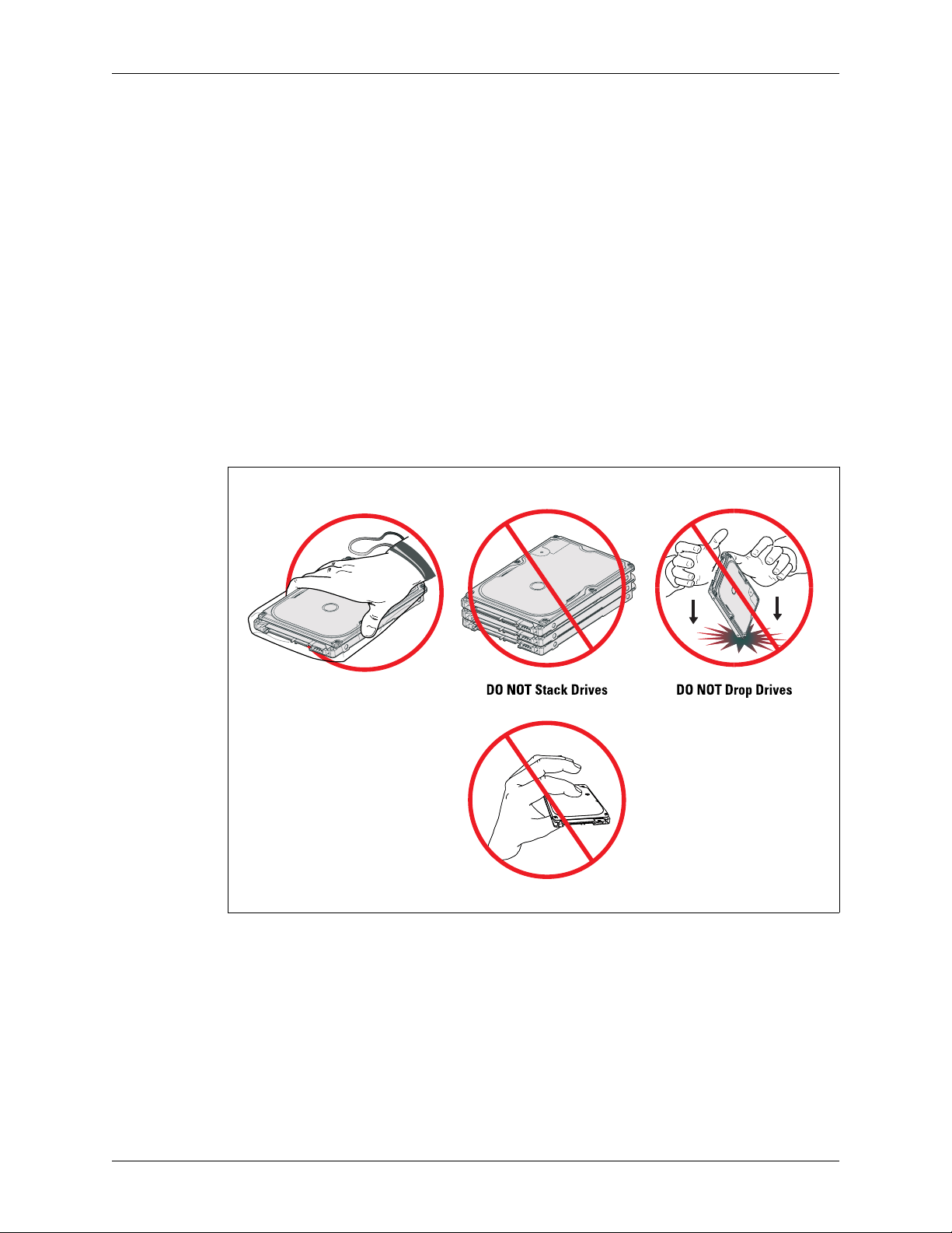
Installation and Setup Procedures WD Green MB500M-6Gb
5.0 INSTALLATION AND SETUP PROCEDURES
Hard drives are precision instruments that must be handled with care to prevent damage. It is important to
understand that drives are typically damaged due to electrostatic discharge (ESD), pressing on the top cover,
rough handling, or shock and vibration. Also refer to the WD 2.5-inch Hard Drive Handling poster (part
number 2378-701047) for details on drive handling.
Important: If your system does not support hot plugging (see “Hot Plug Support” on page 17), it must
be turned off and unplugged before installing your hard drive.
5.1 Unpacking
5.1.1 Handling Precautions
WD products are designed to withstand normal handling during unpacking and installation. Take care
to avoid excessive mechanical shock, pressing on the top cover, or electrostatic discharge (ESD) which
can permanently damage the hard drive and void the warranty. Hard drives are typically damaged
because of ESD, rough handling, or shock and vibration.
Figure 5-1. Drive Handling Precautions
Hard drives are delicate, precision instruments and should be handled with care at all times.
Hard drives are typically damaged by rough handling, shock, vibration, and electrostatic discharge (ESD).
Handle the Drive ONLY by its Sides
DO NOT Press on the Top Cover of the Drive
To avoid ESD problems, wear a properly grounded wrist strap when handling the hard drive. Articles
of clothing generate static electricity. Do not allow clothing to come in direct contact with the hard
drive or circuit board components.
When the drive is not in its shipping container or installed in its proper host enclosure, it must remain
in the antistatic bag. To prevent damage, do not unpack your drive until you are ready to install it.
CAUTION:To avoid damage to internal drive components, do not apply a load greater than
2.6 lbf to a circular 10 mm diameter area anywhere on the top cover. Chassis
design should allow for sufficient clearance and support to prevent loads from
being transferred to the drive top cover.
36 RELEASED 5/2/13 (WD CONFIDENTIAL) 2679-771422-A00
Page 45
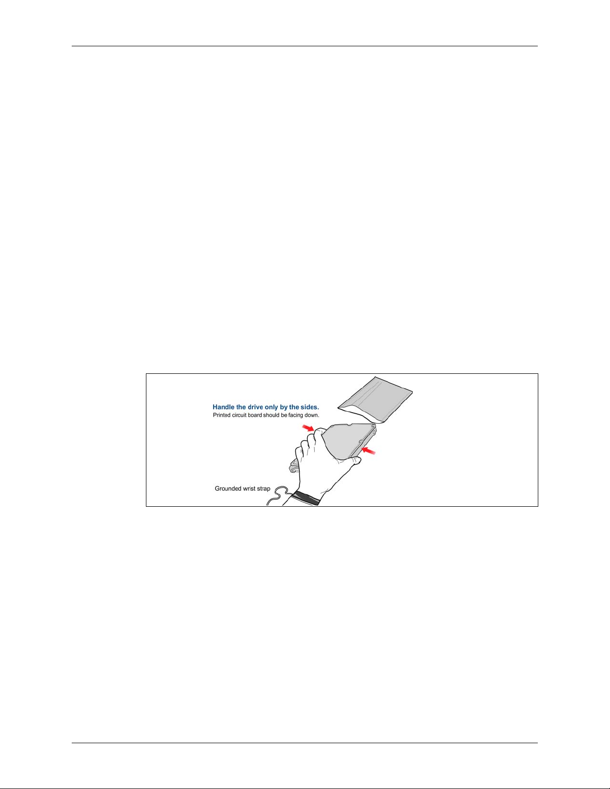
WD Green MB500M-6Gb Installation and Setup Procedures
5.1.2 Inspection of Shipping Container
Carefully examine the container for obvious shipping damage, such as: holes, signs of crushing, or
stains. Notify the carrier and your WD representative if you observe any shipment damage. Always
move the shipping container in the upright position indicated by the arrows on the container.
5.1.3 Removal From Shipping Container
Remove the drive from the shipping container only for inspection or installation. Carefully open the
box. When removing the drive from the box, follow these precautions:
Grasp the drive by the sides only; avoid touching the circuit board components.
Gently place the drive on its antistatic bag on a clean, level, grounded work area.
Do not stack drives or stand the drive on its edge.
CAUTION:When removing the drive from the shipping container, be careful not to drop it.
Dropping the drive can severely damage the head disk assembly or printed
circuit board.
5.1.4 Removal From Static Shielding Bag
Before removing the drive from its static shielding bag:
Make sure that your work station is properly grounded.
Wear a properly grounded wrist strap with good skin contact.
Avoid contact with any component on the printed circuit board.
Figure 5-2. Hard Drive Removal From Static Shielding Bag
After attaching your wrist strap, gently remove the drive from the static shielding bag.
Handle the drive by the sides only; avoid touching the printed circuit board.
Handle the drive with the printed circuit board facing downward during installation.
The unit should not be moved during drive activity.
The unit is not intended as a portable device.
Do not attempt to open the drive and service it yourself. Removing the cover may expose you to
harmful electrical voltages and will void the warranty.
To allow ventilation, do not block the air slots on the underside and rear of the enclosure.
Do not remove the tape seal or any labels from the drive; this will void the warranty.
5.1.5 Moving Precautions
If you need to move your computer, turn off the power to automatically unload the heads. Unloading
moves the heads to a safe, non-data landing zone where they lock into place. This helps protect the
media and the heads from accidental damage due to vibration, moving, or shipping.
2679-771422-A00 RELEASED 5/2/13 (WD CONFIDENTIAL) 37
Page 46

Installation and Setup Procedures WD Green MB500M-6Gb
5.2 Bare Drive Handling External Force
To avoid damage to internal drive components, do not apply a load greater than 2.6 lbf to a circular 10
mm diameter area anywhere on the top cover.
5.3 Mounting Restrictions
Important: Your system must be turned off and unplugged before installing your hard drive.
5.3.1 Orientation
You can mount the hard drive in the X, Y, or Z axis, depending upon the physical design of your
system. For best results, mount the drive with all four screws grounded to the chassis. If all four screws
are not used, see "Grounding" on page 39.
5.3.2 Screw Type and Screw Length Limitations
The hard drive should be mounted to the chassis using four M3 screws. Recommended screw torque is
5 in-lb. Maximum screw torque is 6 in-lb.
CAUTION: Screws that are too long can damage the hard drive. Hard drive screw
penetration can differ between products depending upon hard drive design.
WD's minimum design criteria is to always meet the SFF 8201 industry
standard specification. The industry standard as defined in the SFF 8201,
specifies for Side Mounting a maximum of 3 mm screw penetration, and a
minimum of 3 threads engagement, for Bottom Mounting a maximum of 2.5
mm screw penetration, and a minimum of 2.5 threads engagement.
38 RELEASED 5/2/13 (WD CONFIDENTIAL) 2679-771422-A00
Page 47
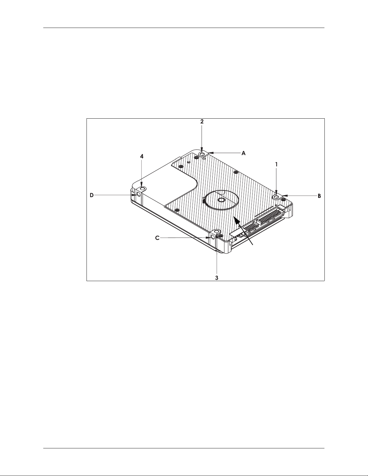
WD Green MB500M-6Gb Installation and Setup Procedures
5.3.3 Grounding
For best results, mount the drive with all four screws in the side grounded to the chassis (positions A, B,
C, and D below). You must ground the drive with at least one mounting screw in position A (side
mounting) or position 1 (top face mounting).
When mounting the drive in a chassis or system, the chassis or system should never contact the crosshatched area “E” to prevent electrical shorting of the PCBA or drive. Contact should be limited to the
side mounting (A,B,C, and D) or top facing mounting (1, 2, 3, and 4).
Figure 5-3. Grounding Diagram
E
Side Mounting – Use four metal screws in A, B, C, and D. If less than four screws are used, remove in
this order: C, D, and then B. You must use a screw in position A.
Top face Mounting–Use four metal screws in 1, 2, 3 and 4. If less than four screws are used, remove in
this order: 2, 4, and then 3. You must use a screw in position 1.
2679-771422-A00 RELEASED 5/2/13 (WD CONFIDENTIAL) 39
Page 48
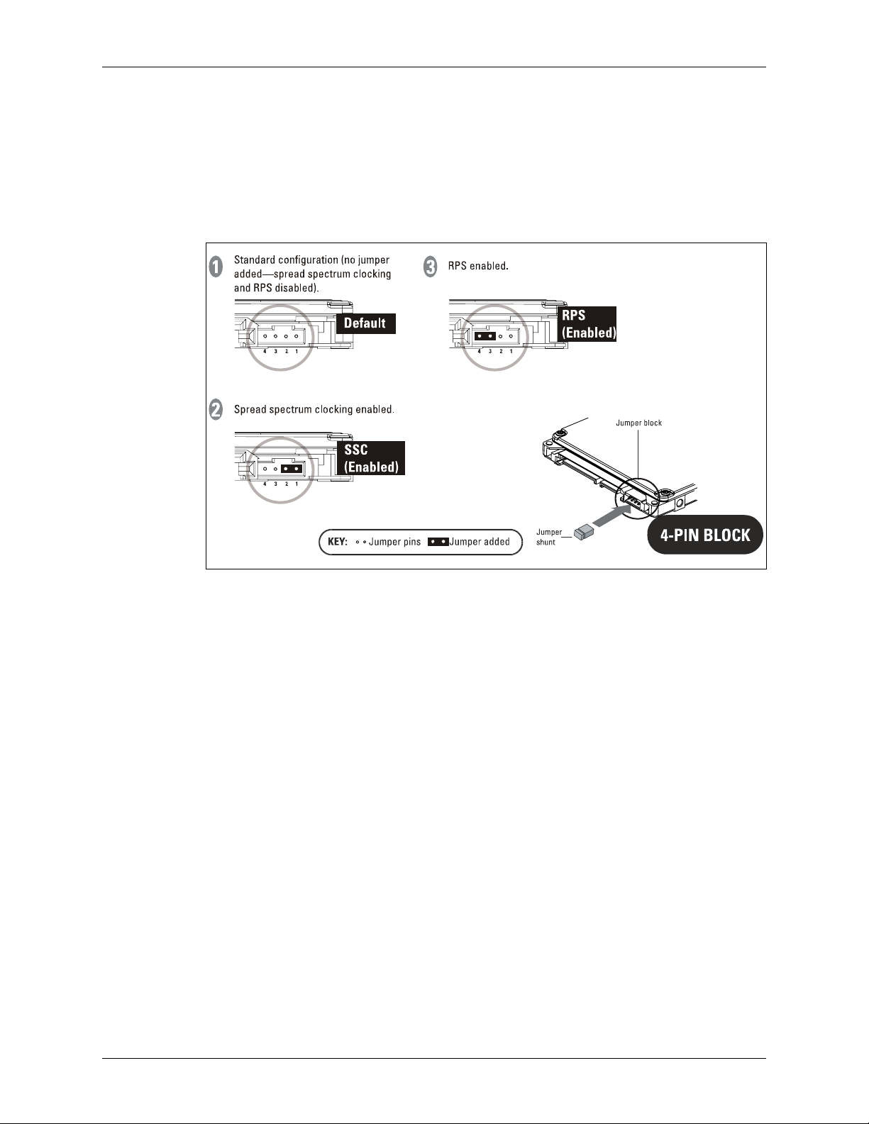
Installation and Setup Procedures WD Green MB500M-6Gb
5.4 Jumper Settings
It is not necessary to put a jumper shunt on the drive for notebook use. Advanced settings for the drive
are as follows:
SSC Mode – Spread spectrum clocking feature. Default setting is disabled.
RPS Mode – RPS feature. Default setting is disabled
Figure 5-4. Jumper Settings for WD SATA Hard Drives
40 RELEASED 5/2/13 (WD CONFIDENTIAL) 2679-771422-A00
Page 49

WD Green MB500M-6Gb Maintenance
6.0 MAINTENANCE
The hard drive requires no preventative maintenance and contains no user-serviceable parts. The service and
repair of WD drives can only be performed at a WD Service Center. Please contact your WD representative for
warranty information and service/return procedures.
Observe the following precautions to prolong the life of the drive:
Do not attempt to open the sealed compartment of the WD drive as this will void the warranty.
Do not lift a WD drive by the printed circuit board.
Avoid static discharge when handling a WD drive.
Avoid harsh shocks or vibrations.
Do not touch the components on the printed circuit board.
Do not obstruct or cover any holes on the drive’s cover. Air must be able to pass through these holes to the
external air filter for normal operation of the drive.
Observe the environmental limits specified for this product.
To protect your data, back it up regularly. WD assumes no responsibility for loss of data. For information
about back-up and restore procedures, consult your operating system manual. There are also a number of
utility programs available that you can use to back up your data.
2679-771422-A00 RELEASED 5/2/13 (WD CONFIDENTIAL) 41
Page 50

Technical Support WD Green MB500M-6Gb
7.0 TECHNICAL SUPPORT
NORTH AMERICA
US/Canada
Monday - Thursday 8:00 am - 9:00 pm
Friday - Sunday 8:00 am - 7:00 pm
EUROPE
Central European Time (CET) 00800.27549338 (toll-free where available) or +31.880062100
Monday - Thursday 9:00 am - 7:00 pm
Friday 9:00 am - 5:00 pm
(Central Time)
7.1 WD Online Services
WD provides a wide variety of technical support services on our Internet site at http://support.wd.com.
800.ASK.4WDC (800.275.4932)
42 RELEASED 5/2/13 (WD CONFIDENTIAL) 2679-771422-A00
Page 51

WD Green MB500M-6Gb Glossary
8.0 GLOSSARY
Active LED Status - WD SATA drives support external LED requirements. It provides an activity LED output
which is ON during command execution and OFF otherwise.
Advanced Format (AF) — Technology adopted by WD and other drive manufacturers to increase media
format efficiencies, thus enabling larger drive capacities.
Annualized Failure Rate (AFR) - A method of measuring failure rates or trends for a group of units at a site.
The rates are based on the monthly total number of returned field failure units divided by the total cumulative
installed base and multiplied by 12 (to annualize the failure rate).
Automatic Defect Retirement - If defective sectors are found during a read or write, they are automatically
mapped out and relocated.
Block - A group of bytes handled, stored, and accessed as a logical data unit, such as an individual file record.
Buffer - A temporary data storage area that compensates for a difference in data transfer rates and/or data
processing rates between sender and receiver.
Data Lifeguard™ — Representing WD's ongoing commitment to data protection, Data Lifeguard data
protection utilities include thermal management, an environmental protection system, and embedded error
detection and repair features that automatically detect, isolate, and repair problem areas that may develop over
the extended use of the hard drive.
Data Transfer Rate -The rate that digital data is transferred from one point to another, expressed in bits per
second or bytes per second.
Defect Management -A general methodology of eliminating data errors on a recording surface by mapping out
known bad areas of the media.
ECC On-the-Fly -A hardware correction technique that corrects errors in the read buffer prior to host transfer
without any performance penalties. These error corrections are invisible to the host system because they do not
require assistance from the drive’s firmware.
Error Correction Code (ECC) -A mathematical algorithm that can detect and correct errors in a data field by
adding check bits to the original data.
F.I.T. (Functional Integrity Testing) - A suite of tests WD performs on all its drive products to ensure
compatibility with different hosts, operating systems, application programs, and peripherals. This testing must
be performed before the product can be released to manufacturing.
Fluid Dynamic Bearings (FDB) - A bearing design that allows ultra-low rotational drag while providing high
lateral stiffness to steadily hold the spinning center of the diskpack for high-accuracy of reading and writing of
data.
Formatted Capacity - The actual capacity available to store data in a mass storage device. The formatted
capacity is the gross capacity minus the capacity taken up by the overhead data required for formatting the
media.
Hot Plugging - The ability to swap out a failed hard drive without having to power down the system or reboot.
Latency - The period of time that the read/write heads wait for the disk to rotate the data to an accessible
position. For a disk rotating at 5400 RPM, the average latency is 5.5 milliseconds.
Logical Address - A storage location address that may or may not relate directly to a physical location. The
logical address is usually used when requesting information from a controller. The controller performs a logicalto-physical address conversion and retrieves the data from a physical location in the storage device.
Logical Block Address - An alternative addressing methodology of identifying a given location on an SATA
drive that permits disk sizes greater than 528 MB.
Perpendicular Magnetic Recording (PMR) - In PMR, the magnetization of each data bit is aligned vertically
rather than longitudinally to the spinning disk. The adjacent bits attract instead of repel (as with bar magnets
placed side by side), creating more thermally stable bits.
PRML (Partial Response Maximum Likelihood) - A read channel using sampled data, active equalization and
Veterbi detection to accurately retrieve the user data off the disk.
2679-771422-A00 RELEASED 5/2/13 (WD CONFIDENTIAL) 43
Page 52

Glossary WD Green MB500M-6Gb
RoHS (Restriction of Hazardous Substances) — WD hard drive products manufactured and sold worldwide
after June 8, 2011, meet or exceed Restriction of Hazardous Substances (RoHS) compliance requirements as
mandated by the RoHS Directive 2011/65/EU. RoHS aims to protect human health and the environment by
restricting the use of certain hazardous substances in new equipment, and consists of restrictions on lead,
mercury, cadmium, and other substances.
Rotational Latency - The amount of delay in obtaining information from a hard drive that can be attributed to
the rotation of the disk.
RPM (Revolutions per Minute) - Rotational speed of the media (disk), also known as the spindle speed. Hard
drives spin at one constant speed. The slower the RPM, the higher the mechanical latencies. Disk RPM is a
critical component of hard drive performance because it directly impacts the rotational latency of the disk
transfer rate.
Serial ATA (SATA) - SATA is the next generation bus interface for hard drives. It is designed to replace Parallel
ATA, and has many advantages including increased transfer rate, improved signal integrity, enhanced data
protection, and hot plugging.
Sector - A 512- or 4K-byte packet of data.
Seek Time - The time it takes for the read/write head to move to a specific block of data on the hard drive. The
average seek time is computed by dividing the time it takes to complete a large number of random seeks by the
number of seeks performed.
Self-Monitoring, Analysis, and Reporting Technology (S.M.A.R.T.) - A technology to assist the user in
preventing possible system down time due to hard drive failure.
S.M.A.R.T. Command Transport (SCT) — The SCT Command Transport feature set provides a method for a
host to send commands and data to a device and for a device to send data and status to a host using log pages.
System-on-Chip - The System-on-Chip (SOC) is the foundation for WD's next generation electronics and
firmware architecture. The native SATA SOC lowers component count by integrating a hard disk controller,
high performance processor, high speed execution SRAM, and read channel in a 128-pin package.
Unrecoverable Error - A read error that cannot be overcome by an ECC scheme or by rereading the data when
host retries are enabled.
World Wide Name (WWN) — The World Wide Name (WWN) defined in ATA/ATAPI-7 is a modification
of the IEEE extended unique identifier 64 bit standard (EUI-64) and is comprised of three major components:
naming authority, organizationally unique identifier (OUI) and serial number. WD's OUI is 0014EEh.
Write Cache - A feature in CacheFlow that posts “command complete” prior to completing the actual write.
44 RELEASED 5/2/13 (WD CONFIDENTIAL) 2679-771422-A00
Page 53

WD Green MB500M-6Gb Index
INDEX
—A—
Acoustics, 10, 11
Active LED Status, 18
Activity indication, 18
Actuator Type, 4
Advanced Formatting, 1, 12, 13, 21
Advanced formatting, 42
Agency Approvals, 11
Annualized Failure Rate, 42
Atmospheric Pressure, 10
Automatic Acoustic Management (AAM), 21
Automatic Defect Retirement, 17
—B—
Buffer Size, 3
Bytes per Sector, 4
—C—
Cabling, 7
CacheFlow6, 18
Commands
SCT, 23
Component Design Life, 10
Cooling, 10
Airflow, 10
Current Requirements, 7
—D—
Data Lifeguard, 15
Data Surfaces, 4
Data Transfer Rate, 3
Defect Management, 17
Dimensions, 5
—E—
ECC, 4
Error Recovery Process, 17
—F—
Fluid Dynamic Bearings (FDB), 13, 18
—G—
Glossary, 42
Grounding, 38
—H—
Host Interface Commands, 21
Identify Drive, 27
S.M.A.R.T., 23
Set Features, 34
Hot Plug Support, 17
—I—
Input Voltage Requirements, 7
Installation and Setup, 35
IntelliPower, 13
Internal Environmental Protection System, 16
—J—
Jumper Settings, 39
Jumper Settings Diagram, 39
—L—
Latency, 3
LED
active status, 18
activity indication, 18
Load/unload cycles, 3
Logical Block Addressing
48-bit, 19
—M—
Maintenance, 40
Model number specification, 11
Mounting Restrictions
Orientation, 37
Screw Size Limitations, 37
—P—
Perpendicular Magnetic Recording (PMR), 14
Power Conservation, 20
Power Dissipation, 7, 9
—R—
Read Cache, 19
Recording Method, 4
Reliability features set, 15
Ripple, 7
RoHS (Restriction of Hazardous Substances), 10
Rotational Speed, 3
—S—
S.M.A.R.T., 20
S.M.A.R.T. Command Transport (SCT), 14
SATA 1.5 Gb/s, 13
SATA 3 Gb/s, 13
SCT, 14
SCT commands, 23
SCT feature set
read/write long, 15
temperature reporting, 15
write same, 14
Security Mode, 20
Passwords, 20
Security Levels, 20
Servo Type, 4
Shock, 8
2679-771422-A00 RELEASED 5/2/13 (WD CONFIDENTIAL) 44
Page 54

Index WD Green MB500M-6Gb
Specifications, 3
Electrical, 7
Environmental, 8
Mechanical, 6
Performance, 3
Physical, 4
Reliability, 10
Spindle Start Time, 3
Staggered Spinup, 18
System-on-Chip (SOC), 14
—T—
Technical Support, 41
Online Services, 41
Temperature
airflow, 10
cooling, 10
thermocouple location, 9
Temperature and Humidity, 9
Thermal Management, 16
Thermocouple location, 9
—U—
Unpacking
Container Inspection, 36
Drive Removal - Container, 36
Drive Removal - Static Shielding Bag, 36
Handling Precautions, 35
Moving Precautions, 36
User Sectors per Drive, 4
—V—
Vibration, 8
—W—
Write Cache, 19
45 RELEASED 5/2/13 (WD CONFIDENTIAL) 2679-771422-A00
Page 55

Western Digital
3355 Michelson Drive, Suite 100
Irvine, California 92612
U.S.A.
For service and literature:
http://support.wd.com
www.wd.com
ASK.4WDC North America
800.
(800.275.4932)
800.832.4778 Spanish
+800.6008.6008 Asia Pacific
00800.27549338 Europe (toll free where available)
+31.880062100 Europe/Middle East/Africa
2679-771422-A00
May 2013
WD CONFIDENTIAL
 Loading...