

Page 1

800-1910 (REV. 4-87)
WD1002
WD1003
WD1002
WD1003
USER’S GUIDE
Page 2
DOCUMENT SCOPE
This document describes the hardware and software installation of the following boards:
WD1002-WAH Winchester Disk Controller
WDl002-WA2 Winchester/Floppy Disk Controller
WDl003-WAH Winchester Disk Controller
WDl003-WA2 Winchester/Floppy Disk Controller
NOTE
These controllers are designed for use in IBM Personal
computer ATs or other AT-compatible computers with a 16bit data bus.
The use of the term controller refers to all boards described
within this document. When a specific reference is made to a
particular board. the appropriate WD part number is used.
HARDWARE INSTALLATION
This section briefly describes installation of your hardware. If
the disk drive(s) is(are) being installed internally, it is best to
locate the controller in the nearest available expansion slot to
the drive.
CAUTION
Handle the controller board by the ends of the
board. Some of the chips are static sensitive and
damage may occur If the board is incorrectly
handled.
NOTE
Only verify the jumper settings in Step 1. Modification of the
standard factory jumper settings on any equipment described
in this document is rarely necessary. Modify jumpers only
under the direction of a qualified individual; i.e., your dealer.
1.
Verify controller jumper settings. Refer to pages 3
through 6 for jumper setting information.
2.
Verify termination on last drive. Verify proper setting of
drive select switches on drive; i.e., set the drive select
switches for drive select 1 or 2. Refer to your system
owner's manual for information about proper drive
termination and select switches.
3
. Remove the blank expansion slot bracket. Put the bracket
away and save it for possible future use. The screw will
be used to hold the new controller board in place.
1
4.
Attach 34-pin control connector pin 1 to J1 (J5 for
WDl002-WA2 or WDl003-WA2) pin 1. Pin 1 is in the
lower left hand corner of J1. Pin 1 is in the upper left
hand corner of J5.
5.
Connect control cable to drive.
6.
Attach 20-pin data connector to J2 (drive C or 1) for the
WD1002-WAH or WD1003-WAH (J4 for WD1002WA2 or WD1003-WA2).
7.
Attach 20-pin data connector to J3 (Drive D or 2).
8.
Connect data cables to drives.
9.
Attach 34-pin floppy cable connector to J1. Connect
cable to floppy drive. This step applies to WD1002-WA2
and WDl003-WA2 users only.
10.
Attach Winchester activity LED connector to J6 for all
controllers except the WDl002-WAH. The reference
designator for the Winchester activity LED connector on
the WD1002-WAH is J4.
11.
Install the controller board into the expansion slot. Make
sure that the board is seated properly by pressing down
on both ends of the board. Secure the board with the
bracket screw.
12.
Remove or disable any other floppy controller in your
system
IF YOU ARE INSTALLING A
WD1002-
WA2
OR
WD1003-WA2.
2
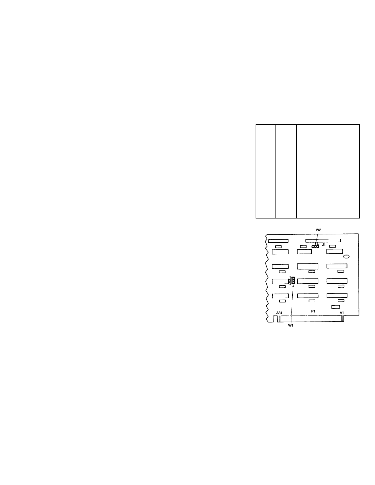
WD 1002-WAH JUMPER SETTINGS
JUMPER PIN
CONNECTS
DESCRIPTION
NOTE
DO NOT MOVE JUMPER W1 UNLESS YOUR
OPERATING SYSTEM IS CONFIGURED TO
ACCEP T TWO H A RD DI SK C ON TRO LLERS .
CERTAIN OPERATING SYSTEMS SUPPORT
TWO CON TROLLERS IN THE SAME
SYSTEM. IBM DOS AND MANY IBMCOMPATIBLE OPERATING SYSTEMS DO
NOT SUPPORT THIS FEATURE.
W1 Primary/secondary I/O address jumper.
1 to 2 Standard factory setting. Jumper in this position
selects base primary addresses IF0 hex thru IF7
and 3F6 hex thru 3F7 hex.
2 to 3 Jumper in this position selects base secondary
addresses 170 hex thru 177 hex and 376 hex thru
377 hex.
W2 Latched Status Register Jumper
L S tandard factory setting. Current drive in use is
continuously selected. The Winchester Activity
LED remains continuously lit even though the
drive is n ot con stan tly acces s ed by the ho st. Us ed
for IBM Personal Computer ATs.
W2 NL Current drive in use is selected only w hen the
WD1002-WAH is communicating with the drive.
The Winchester Activity LED only lights when the
controller acces ses the driv e. Used for Compaq
286 computers.
WD1002–WAH JUMPER LOCATIONS
3
Page 3

WD1002-WA2 JUMPER SETTINGS
PIN
CONNECTS
DESCRIPTION
NOTE
DO NOT MOVE
PRIMARY
ADDRESS JUMPERS
UNLESS YOUR OPERATING SYSTEM IS
CONFIGURED TO ACCEPT TWO HARD DISK
CONTROLLERS. CERTAIN OPERATING SYSTEMS
SUPPORT TWO CONTROLLERS IN THE SAME
SYST EM. IBM DOS AND MANY IBM-COMPATIBL E
OPERATING SYSTEMS DO NOT SUPPORT THIS
FEATURE.
E2 to E3 Standard factory setting. Selects primary address 3F2,
3F4/3F7 hex for the floppy disk drives.
E5 to E6 Standard factory setting. Selects primary addresses 1FO
hex through lF7 hex, and 3F6 hex and 3F7 hex for the
Winchester diskdrives.
El to E2 Selects secondary addresses 372, 374/377 hex for the
floppy disk drives.
E4 to E5 Selects secondary addresses 170 hex through I 77 hex and
376 hex and 377 hex for the Winchester disk drives.
E7 to E8 Jumper must he installed at all times
. DO NOT
REMOVE.
4
WD1003-WA2 JUMPER SETTINGS
JUMPER POSITION FUNCTION
W1 No jumper Status Read is non-latched. Dynamic drive select; i.e..
SELECT = DRIVE BUSY. Used for Compaq 286s.
Jumper Standard factory setting. Status read is latched. Static
drive select (SELECT asserted except during RESET).
Used for IBM Personal Computer ATs.
NOTE
Do NOT MOVE PRIMARY ADDRESS JUMPERS
UNLESS YOUR OPERATING SYSTEM IS
CONFIGURED TO ACCEPT TWO HARD DISK
CONTROLLERS. CERTAIN OPERATING
SYSTEMS SUPPORT TWO CONTROLLERS IN
THE SAME SYSTEM. IBM DOS AND MANY IBM
COMPATIBLE OPERATING SYSTEMS DO NOT
SUPPORT THIS FEATURE
W2 No Jumper Standard factory setting. Primary addresses selected.
Jumper Secondary addresses selected.
W3 No jumper This configuration used with WD1lC00A-22 or when
W5, pins 2 and 3 are jumpered.
Jumper Required only on early units with WD11C00-22 and
W5. pins 1-2 jumpered. DO NOT JUMPER WITH
WD11C00A-22 INSTALLED.
W4 Jumper 2-3 Standard factory setting. Ties firmware sense bit input
high
Jumper 1-2 Supports 2 head. 612 cylinder second drive with
standard system setup for 4 head. 306 cylinder drive.
W5 Jumper 2-3 Standard factory setting.
Jumper 1-2 Internal signal of Power-up circuit controls WG enable.
W6 Jumper 2-3 Standard factory setting. Ties input high.
Jumper 1-2 Ties input low. The 35 µsec step rate cannot be selected
with W6 in this position. Instead, the 16 µsec step rate is
selected.
5
Page 4

WD1003-WA2 JUMPER SETTINGS
PIN CONNECTS DESCRIPTION
NOTE
DO NOT MOVE PRIMARY ADDRESS JUMPERS
UNLESS YOUR OPERATING SYSTEM IS CONFIGURED
TO ACCEPT TWO HARD DISK CONTROLLERS.
CERTAIN OPERATING SYSTEMS SUPPORT TWO
CON TRO LLERS IN THE SA M E SY S TEM. IBM D OS A ND
MANY IBM-COMPATIBLE OPERATING SYSTEMS DO
NOT SUPPORT THIS FEATURE.
E2 to E3 Standard factory setting. Selects primary addresses.
E5 to E6 Standard factory setting. Selects primary addresses.
El to E2 Selects secondary addresses.
E4 to E5 Selects secondary addresses.
E7 to E8 Standard factory setting. Supports 360 RPM floppy disk drives.
ES to E9 Jumper in this position selects 300 RPM floppy disk drives.
6
SOFTWARE INSTALLATION
This section contains instructions for preparing (low level
format, etc.) your operating system to recognize the Western
Digital controller.
1
. Insert your system Diagnostic Diskette (or equivalent).
2.
Turn on the power
3.
Boot diagnostic and select setup option.
4
. Set clock etc.
CAUTION
Avoid system damage by consulting your
Technical Reference manual to ensure that your
drive type is supported by your host BIOS drive
tables. Not all AT-compatibles share the same
drive tables as IBM
.
5.
Select proper drive type. Consult your Technical Reference Manual for further information on these parameters.
NOTE
Step 6 requires execution of low level formatting. Use of the
IBM Advanced Diagnostic (or similar program for IBMcompatibles) is necessary since these controllers contain no
on-board Basic Input/Output System (BIOS) ROM.
6.
Insert your Advanced Diagnostic diskette and execute
low level Format. Follow instructions in your reference
manual.
7.
Insert System Diagnostic Diskette (or equivalent) after
the system finishes the low level format.
8.
Load and execute the FDISK and FORMAT programs.
Follow instructions in your reference manual.
7
 Loading...