

Page 1

WD
Array Management Setup
User Manual
Page 2

WD
Array Management Setup
User Manual
Information furnished by WD is believed to be accurate and reliable. However, no responsibility is assumed by WD for its use nor for
any infringement of patents or other rights of third parties which may result from its use. No license is granted by implication or
otherwise under any patent or patent rights of WD. WD reserves the right to change specifications at any time without notice.
© 2005 Western Digital Technologies, Inc. All rights reserved.
Western Digital is a registered trademark; and WD, the WD logo, and EasyBuild are trademarks of Western Digital Technologies, Inc.
Other marks may be mentioned herein that belong to other companies.
2779-001011-A01 Sep 2005
Page 3
Table of Contents
1 Chapter 1: Introduction
AMS Components . . . . . . . . . . . . . . . . . . . . . . . . . . . . . . . . . . . . . . . . . . . 1
How They Work Together . . . . . . . . . . . . . . . . . . . . . . . . . . . . . . . . . . . . . 1
AMS Installation Options. . . . . . . . . . . . . . . . . . . . . . . . . . . . . . . . . . . . . . 2
4 Chapter 2: Installation
Installation Locations . . . . . . . . . . . . . . . . . . . . . . . . . . . . . . . . . . . . . . . . . 4
Operating System Support . . . . . . . . . . . . . . . . . . . . . . . . . . . . . . . . . . . . . 6
Network Requirements. . . . . . . . . . . . . . . . . . . . . . . . . . . . . . . . . . . . . . . . 6
Installation Procedure . . . . . . . . . . . . . . . . . . . . . . . . . . . . . . . . . . . . . . . . . 6
AMS Installation. . . . . . . . . . . . . . . . . . . . . . . . . . . . . . . . . . . . . . . . . . . . . 6
10 Chapter 3: Initial Setup
Launch AMS. . . . . . . . . . . . . . . . . . . . . . . . . . . . . . . . . . . . . . . . . . . . . . . 10
Remote AMS Login . . . . . . . . . . . . . . . . . . . . . . . . . . . . . . . . . . . . . . . . . 13
Create a New User . . . . . . . . . . . . . . . . . . . . . . . . . . . . . . . . . . . . . . . . . . 15
Create an Array. . . . . . . . . . . . . . . . . . . . . . . . . . . . . . . . . . . . . . . . . . . . . 16
Setup Alert Notification . . . . . . . . . . . . . . . . . . . . . . . . . . . . . . . . . . . . . . 18
Specify Alert Notification Events . . . . . . . . . . . . . . . . . . . . . . . . . . . . . . . 20
22 Chapter 4: AMS User Interface
Tree View . . . . . . . . . . . . . . . . . . . . . . . . . . . . . . . . . . . . . . . . . . . . . . . . . 23
Tree View and Component Specific Menus . . . . . . . . . . . . . . . . . . . . . . . 24
Object View . . . . . . . . . . . . . . . . . . . . . . . . . . . . . . . . . . . . . . . . . . . . . . . 24
Information View . . . . . . . . . . . . . . . . . . . . . . . . . . . . . . . . . . . . . . . . . . . 25
Status Bar . . . . . . . . . . . . . . . . . . . . . . . . . . . . . . . . . . . . . . . . . . . . . . . . . 25
Pulldown Menus. . . . . . . . . . . . . . . . . . . . . . . . . . . . . . . . . . . . . . . . . . . . 25
Toolbar. . . . . . . . . . . . . . . . . . . . . . . . . . . . . . . . . . . . . . . . . . . . . . . . . . . 28
Popup Menus . . . . . . . . . . . . . . . . . . . . . . . . . . . . . . . . . . . . . . . . . . . . . . 28
31 Chapter 5: RAID Monitoring and Maintenance with AMS
Remote AMS . . . . . . . . . . . . . . . . . . . . . . . . . . . . . . . . . . . . . . . . . . . . . . 31
Message Server IP Address Change . . . . . . . . . . . . . . . . . . . . . . . . . . . . . . 34
Local AMS . . . . . . . . . . . . . . . . . . . . . . . . . . . . . . . . . . . . . . . . . . . . . . . . 35
User Management. . . . . . . . . . . . . . . . . . . . . . . . . . . . . . . . . . . . . . . . . . . 36
Alert Notification . . . . . . . . . . . . . . . . . . . . . . . . . . . . . . . . . . . . . . . . . . . 39
Specify Alert Notification Events . . . . . . . . . . . . . . . . . . . . . . . . . . . . . . . 41
Controller . . . . . . . . . . . . . . . . . . . . . . . . . . . . . . . . . . . . . . . . . . . . . . . . . 43
Arrays . . . . . . . . . . . . . . . . . . . . . . . . . . . . . . . . . . . . . . . . . . . . . . . . . . . . 46
Synchronize an Array . . . . . . . . . . . . . . . . . . . . . . . . . . . . . . . . . . . . . . . . 54
Delete an Array. . . . . . . . . . . . . . . . . . . . . . . . . . . . . . . . . . . . . . . . . . . . . 55
TABLE OF CONTENTS - i
Page 4

56 Appendix A: RAID Concepts
RAID . . . . . . . . . . . . . . . . . . . . . . . . . . . . . . . . . . . . . . . . . . . . . . . . . . . . 56
58 Appendix B: Partition and Format
62 Appendix C: Networking Issues
IP Address. . . . . . . . . . . . . . . . . . . . . . . . . . . . . . . . . . . . . . . . . . . . . . . . . 62
DHCP Issues . . . . . . . . . . . . . . . . . . . . . . . . . . . . . . . . . . . . . . . . . . . . . . 63
64 Appendix D: WD Service and Support
TABLE OF CONTENTS - ii
Page 5

WD ARRAY MANAGEMENT SETUP
USER MANUAL
Chapter 1: Introduction
The WD Array Management Setup (AMS) is a utility application designed specifically for
monitoring and managing the WD SATA RAID Controller. AMS runs over a local area
network and makes possible RAID monitoring and management from any computer on the
network and even over Internet. This allows your IT manager to watch your RAIDs and take
care of them over the network.
AMS Components
There are three components to AMS. Depending on your installation, all three may be on the
same workstation or work separately across your network:
Monitoring Utility—The Monitoring Utility is a Graphic User Interface (GUI) that reports
on the condition of the RAID array. It receives and displays reports on RAID condition and
operation through the Message Server. The Monitoring Utility works on any PC with a
TCP/IP network connection to your RAID.
When installed on the computer that operates the RAID, the Monitoring Utility also provides
a complete set of RAID management tools.
Message Server—The Message Server normally runs on a network file server but can also run
on the PC controlling the RAID.
Message Agent—The Message Agent runs on the PC that controls the RAID, called the
"RAID PC". The Message Agent directly monitors the RAID and sends messages through the
Message Server to all PCs running the Monitoring Utility.
How They Work Together
The WD Array Management Setup (AMS) utility provides and easy way to set up, monitor,
modify, and repair your RAID. AMS works with the WD SATA RAID Controller.
AMS watches the RAID and when significant events happen, or it discovers a problem, the
Message Agent sends a warning to the Message Server. The Message Server passes the warning
along to all PCs running the Monitoring Utility.
Warnings appear on the PC in the form of email messages and popup alerts. You can select
either one or both. You can also select which events and problems AMS will report.
A major benefit of AMS is that it runs over a TCP/IP network. This enables remote
monitoring of your RAIDs, including offsite monitoring over an Internet connection.
Once you become aware of a problem, go to the PC that controls the RAID, called the
"RAID PC" to take corrective action. If you have more than one RAID PC on your network,
AMS will indicate which one has the problem.
AMS allows monitoring access only through the network. Management access occurs only at
the RAID PC.
CHAPTER 1: INTRODUCTION - 1
Page 6
WD ARRAY MANAGEMENT SETUP
USER MANUAL
AMS Installation Options
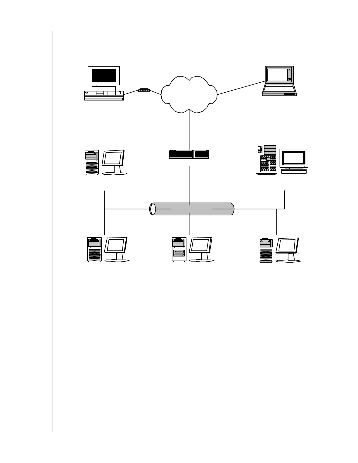
1. Following are some examples of ways you can incorporate AMS into your network and
RAID systems.
Ho me -ba se d P C
+ Monitoring Utility
A ne tworked PC
+ Monitoring Utility
Mo de m
Internet
L apt op com pute r
+ Monitoring Utility
Router & Firew all
Ne twor k Fi l e S er ve r
+ Message Server
Comp any LAN
PC
+ WD SATA RAID Controller
+ Message Agent
PC
+ WD SATA RAID Cont rolle r
+ Int erna l RAID a rray
Figure 1. LAN and Internet Connections
PC
+ WD SATA RAID Controller
+ Message Agent
CHAPTER 1: INTRODUCTION - 2
Page 7
WD ARRAY MANAGEMENT SETUP
g
r
r
USER MANUAL
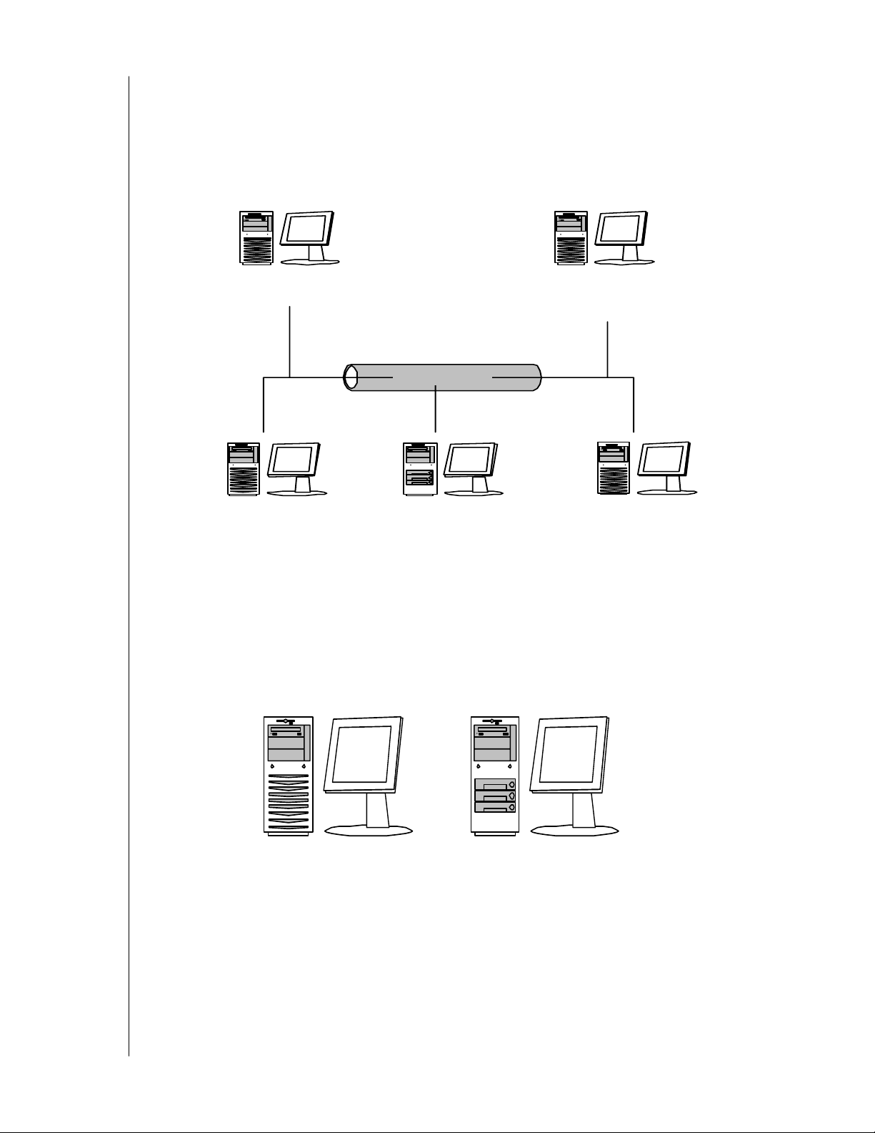
In the following example, there are three PCs with WD SATA RAID Controllers connected
to the company's LAN. The AMS Message Agent runs on each of the PCs with a WD SATA
RAID Controller. The AMS Message Server runs on the company's file server. The AMS
Monitoring Utility runs on networked PCs and also on remote PCs connecting to the
company network through the Internet. With this arrangement, you can monitor RAID
condition and activity from offsite, such as a hotel room or home office.
A networked PC
+ Monitoring Utility
+ WD SATA RAID Controller
+ Message Agent
PC
+ WD SATA RAID Controller
Company LAN
PC
+ Internal RAID array
+ Messa
e Agent
A network ed P C
+ Monitoring Utility
+ Message Server
PC
+ WD SATA RAID Controlle
+ Message Agent
Figure 2. Company LAN without a File Server
In the above example, there are three PCs with WD SATA RAID Controllers connected to
the company's LAN, the same as before. But this network has no file server, so the AMS
Message Server runs on one of the networked PCs. AMS Monitoring Utility runs on both
networked PCs. If this LAN were upgraded with a suitable router and an Internet connection,
you could set up offsite monitoring as in Figure 1.
PC
+ WD SATA RAID Controller
+ Monitoring Utilit y
+ Message Agent
+ WD SATA RAID Controlle
PC
+ Internal RAID array
+ Monitori ng Ut ility
Figure 3. PCs with Internal RAID
WD's SATA RAID Controller is designed to setup and control a RAID within the PC's
enclosure. They have the same need of monitoring and management as an external RAID
subsystem. All three AMS components run on the PC itself.
CHAPTER 1: INTRODUCTION - 3
Page 8

WD ARRAY MANAGEMENT SETUP
USER MANUAL
Chapter 2: Installation
To install WD Array Management Setup (AMS) is an uncomplicated procedure, once you
understand your systems and how you want to use AMS. The purpose of this Chapter is to
help you plan and carry out your installation of AMS.
By way of review, AMS consists of three components:
! Monitoring Utility
! Message Server
! Message Agent
These were described in the previous chapter. Before proceeding with the installation, you
must know which component goes where. If you plan to run AMS over a network, you must
know the IP addresses of each computer on the network that will be involved in your RAID
monitoring and management activity.
Installation Locations
In the table below are possible locations for each of the three AMS components.
Monitoring Utility Message Server Message Agent
Internet-connected PC
Network PC
Network File Server
RAID PC
Table 1. Acceptable AMS Component Installation Locations
•
••
••
•••
Monitoring Utility
The Monitoring Utility installs on any computer you will use to monitor and manage the
RAIDs.
If your RAID runs without a network connection, install it on the RAID PC with the rest of
the AMS components.
If your RAIDs are networked, you can install the Monitoring Utility on any computer
connected to the network.
If your company has networked RAIDs and Internet access, you may choose to install the
Monitoring Utility on a laptop or home-based PC for dial-in remote access.
CHAPTER 2: INSTALLATION - 4
Page 9
WD ARRAY MANAGEMENT SETUP
USER MANUAL
Limit your installation to the computers of RAID users and your IT administrator. AMS
features password protection to further limit access and provide security of your data.
Home-based PC
+ Monitoring Utility
A ne tworked PC
+ Monitoring Utility
PC
+ WD SATA RAID Controller
+ Message Agent
Mo dem
Internet
Router & Firew all
Comp any LAN
PC
+ W D SATA RAID Cont ro ller
+ Int erna l RAID array
L apt op com pute r
+ Monitoring Utility
Network File Server
+ Message Server
PC
+ W D SATA RAID Cont ro ller
+ Message Agent
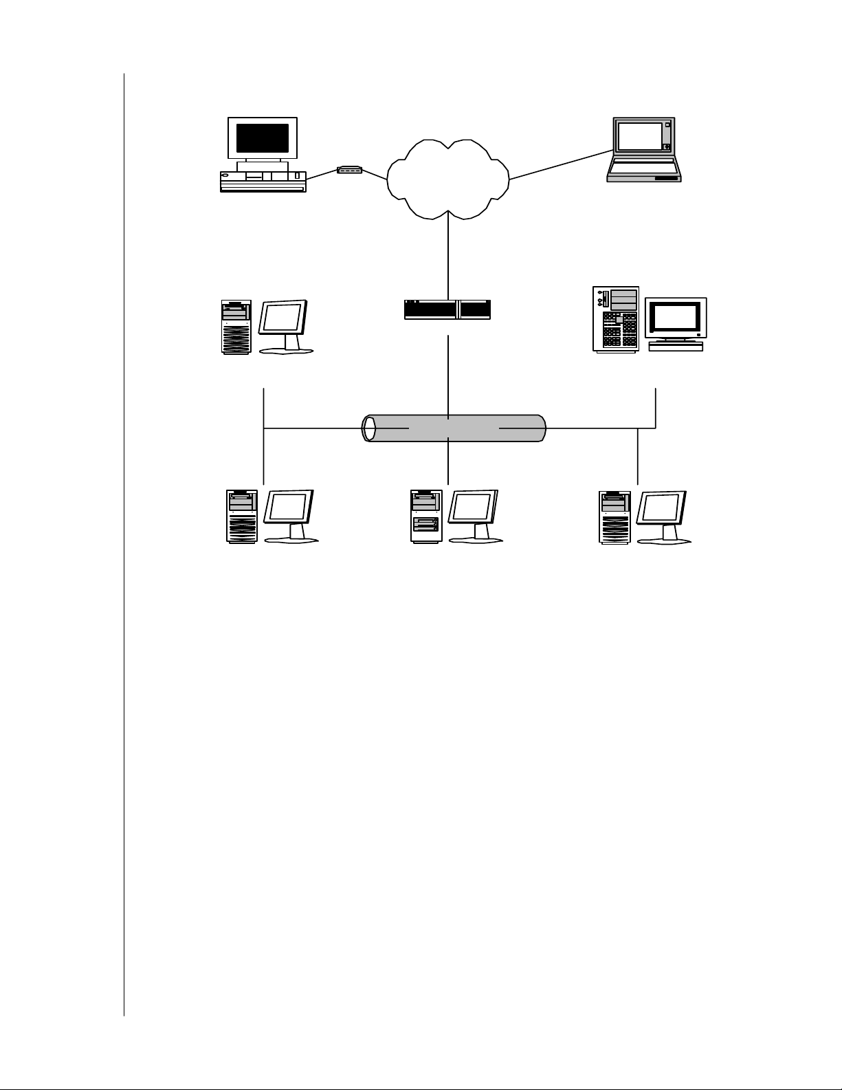
Figure 4. Networked RAID has many installation options
Message Server
The Message Server is required if your RAID PC connects to a network.
If you want run AMS over a network, install the Message Server on one of your networked
computers including a file server, a networked PC or the RAID PC.
Only one installation of the Message Server is required for AMS to work over a network. You
may install Message Server on more than one network PC or file server, but AMS's network
configuration will only use one of them, thus any additional installations are useless.
Do not install the Message Server on any PC that may be disconnected from the network,
such as a laptop or a computer that connects via the Internet. Not only will a disconnect cause
AMS to fail, but reconnecting again may involve time-consuming network configuration.
Network configuration is discussed later in this chapter.
Message Agent
The Message Agent installs on the RAID PC, whether your RAID is networked or not. For
AMS to monitor and manage a RAID, it must have Message Agent installed.
If you have more than one AMS-compatible RAID PC on your network, you may install a
copy of Message Agent on all of them.
CHAPTER 2: INSTALLATION - 5
Page 10
WD ARRAY MANAGEMENT SETUP
USER MANUAL
Operating System Support
AMS is a utility designed to run on top of previously installed WD SATA RAID Controller.
Generally, if your PC runs the WD SATA RAID Controller properly, it will run AMS also.
Windows 2003 Server, XP, or 2000 operating systems are required to take full advantage of all
the features of AMS. In some cases, you can run AMS on other Windows operating systems.
This becomes an issue when running AMS over a network where there are PCs with different
operating systems.
Network Requirements
If you plan to install AMS on a network be sure all the hosts and servers are connected and
running. That is, each of the PCs, RAIDs and Servers must have a working network
connection before you install AMS.
For AMS to be configured over a network, you must know the IP (network) address of the
RAID PC(s) in your system. The Message Server uses IP addresses to communicate with the
Message Agent on the RAID PCs and the Monitoring Utility on the network PCs.
See Appendix C: Networking Issues for help in finding the IP Address of the RAID PC.
Installation Procedure
Before you start...
If you are installing AMS to run over a network, determine the computers and servers onto
which you will install AMS. Obtain the IP addresses of all RAID PCs where AMS will be
installed.
AMS Installation
With that information ready, follow these steps to install AMS on each computer or server:
1. Boot the PC/server and launch Windows.
2. If the computer is already running, exit all programs.
3. Insert the WD RAID setup and management CD into your CD-ROM
drive.
4. Open the CD and locate the AMS folder.
5. Inside the AMS folder, look for the AMS Installer icon (right).
CHAPTER 2: INSTALLATION - 6
Page 11

WD ARRAY MANAGEMENT SETUP
6. Double-click the icon to run the installer. The opening screen appears.
USER MANUAL
Figure 5. AMS Setup Opening Screen
7. Click Next or press ENTER to continue.
Figure 6. The License Agreement
8. When the License Agreement appears, click Yes to agree to the terms and continue the
installation. If you click No, AMS Setup will exit.
CHAPTER 2: INSTALLATION - 7
Page 12
WD ARRAY MANAGEMENT SETUP
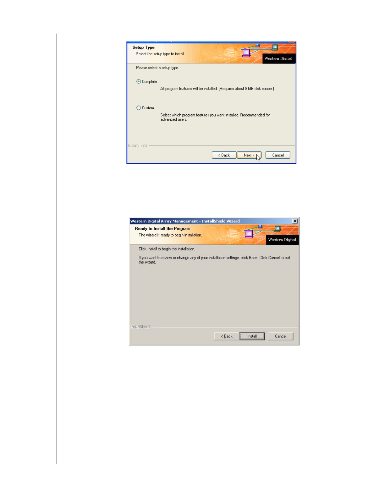
Figure 7. The Setup Type dialog box
USER MANUAL
9. In the Setup Type dialog box, make your choice between Complete (Recommended) and
Custom installation. Use the Custom installation to change install locations or to deselect
individual components.
10. Click Next or press Enter to continue.
Figure 8. Ready to Install dialog box
11. In the Ready to Install dialog box, click Install or press Enter to continue.
CHAPTER 2: INSTALLATION - 8
Page 13

WD ARRAY MANAGEMENT SETUP
Figure 9. Add User Account dialog box
USER MANUAL
12. When the Add User Account dialog box appears, you may accept the default name or
enter a new one in the Name field.
13. Enter your password in the Password and Confirm Password fields. When you are done,
click Next or press Enter to continue.
Note: If you are only installing the Message Server, this dialog box does not appear.
Figure 10. Installation Complete
14. When the Install Complete dialog box appears, you have the option to:
- Create AMS shortcuts on your Desktop
- Register AMS online
Both of these options are recommended.
15. Click Finish or press Enter when you are done.
This completes the AMS installation. Go on to Chapter 3: Initial Setup.
CHAPTER 2: INSTALLATION - 9
Page 14
WD ARRAY MANAGEMENT SETUP
USER MANUAL
Chapter 3: Initial Setup
After you have completed installation, you must set up your AMS Monitoring Utility to work
with your RAID.
Launch AMS
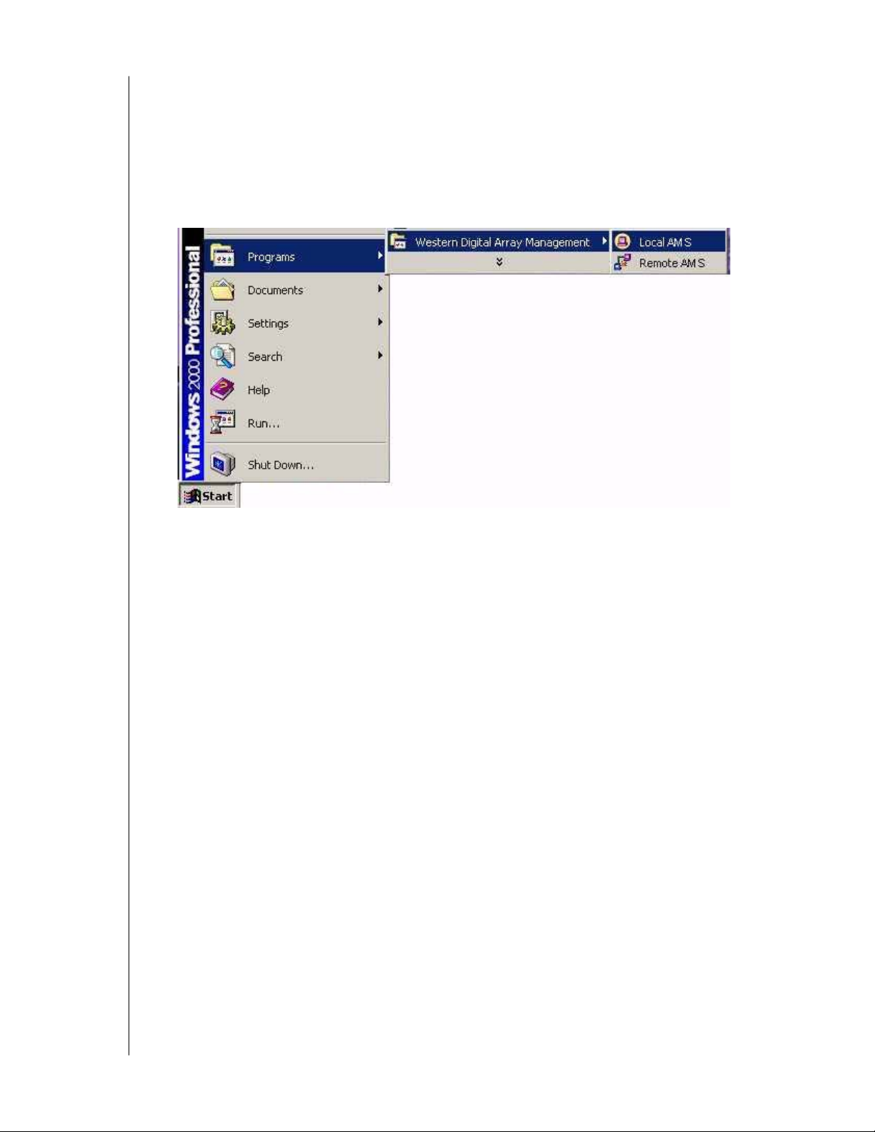
Figure 11. AMS on the Desktop and in the Start Menu
To Start AMS, click on a Desktop icon or go to Start > Programs > WD Array Management
and select:
Local AMS—Use to monitor and manage the WD SATA RAID Controller in your PC
Remote AMS—Use to monitor WD SATA RAID controllers over your network
Note: If you only installed the Message Server, this shortcut does not appear. The Message
Server works only through network connections and has no user interface. Go to the RAID
PC or a Networked PC to setup AMS.
CHAPTER 3: INITIAL SETUP - 10
Page 15
WD ARRAY MANAGEMENT SETUP
USER MANUAL
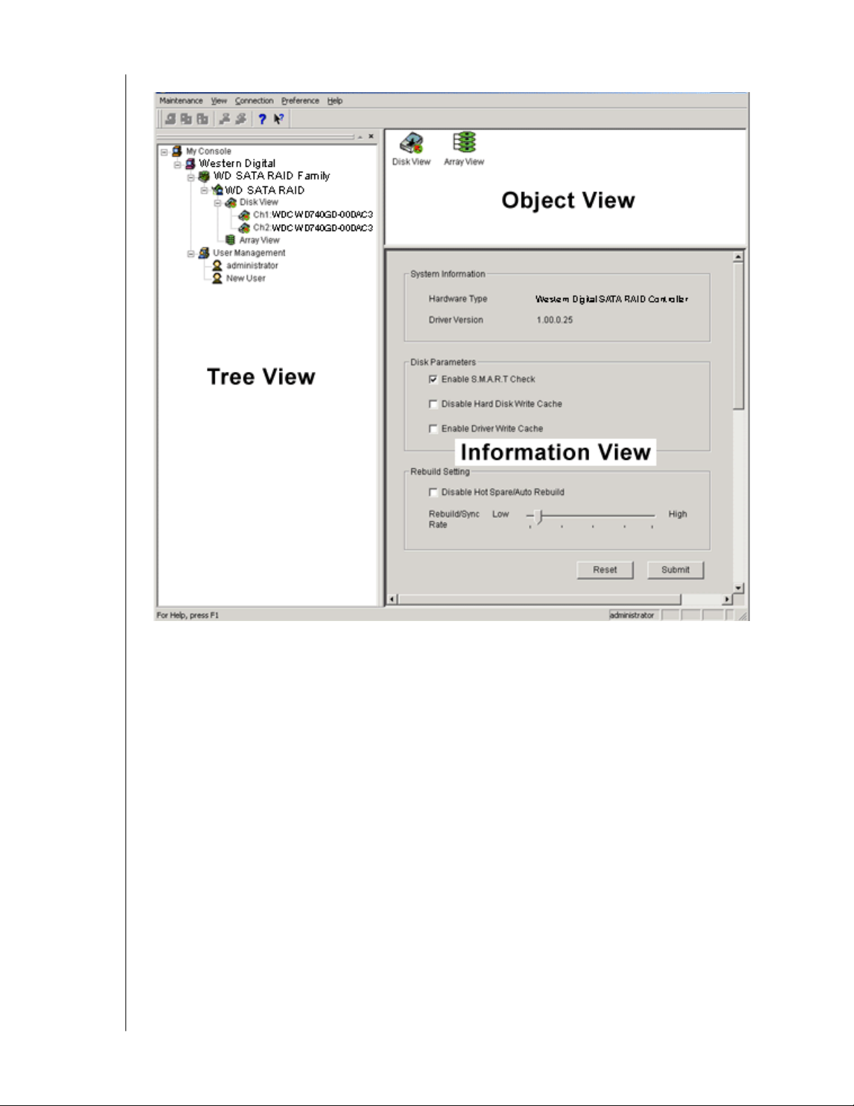
Figure 12. The AMS Monitor Window
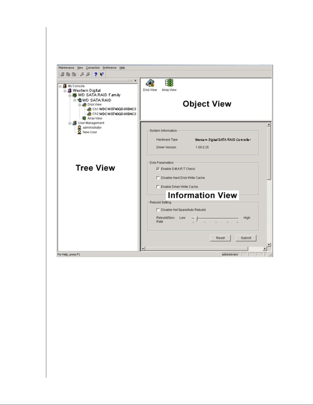
The Monitor window is the user interface for AMS. It has three views:
Tree View—Displays the elements of your RAID system. It works like Windows Explorer
with hierarchical menus. You can expand individual items to see their components.
Object View—Displays icons representing the devices below the highlighted device in the
Tre e V i e w.
Information View—Displays information on the item highlighted in the Tree View. This
may include text boxes, list boxes, fields and buttons. It varies with
CHAPTER 3: INITIAL SETUP - 11
Page 16
WD ARRAY MANAGEMENT SETUP
USER MANUAL
Local Agent Log In
Launch Local AMS. The AMS user interface appears:
Figure 13. Log In to Local AMS
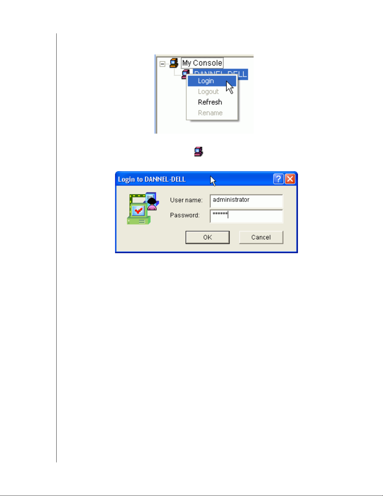
1. Right click on the RAID Machine icon in Tree View. Select Login from the popup
menu. The Login dialog box appears.
Figure 14. Login Dialog Box
2. In the Login dialog box, type your Username and Password, and click OK.
Initially, administrator is the only user. Use the administrator's password selected during
installation.
CHAPTER 3: INITIAL SETUP - 12
Page 17
WD ARRAY MANAGEMENT SETUP
USER MANUAL
Remote AMS Login
Remote AMS works over your network. Therefore it requires additional steps the first time
you log on. Launch Remote AMS. When the AMS user interface appears:
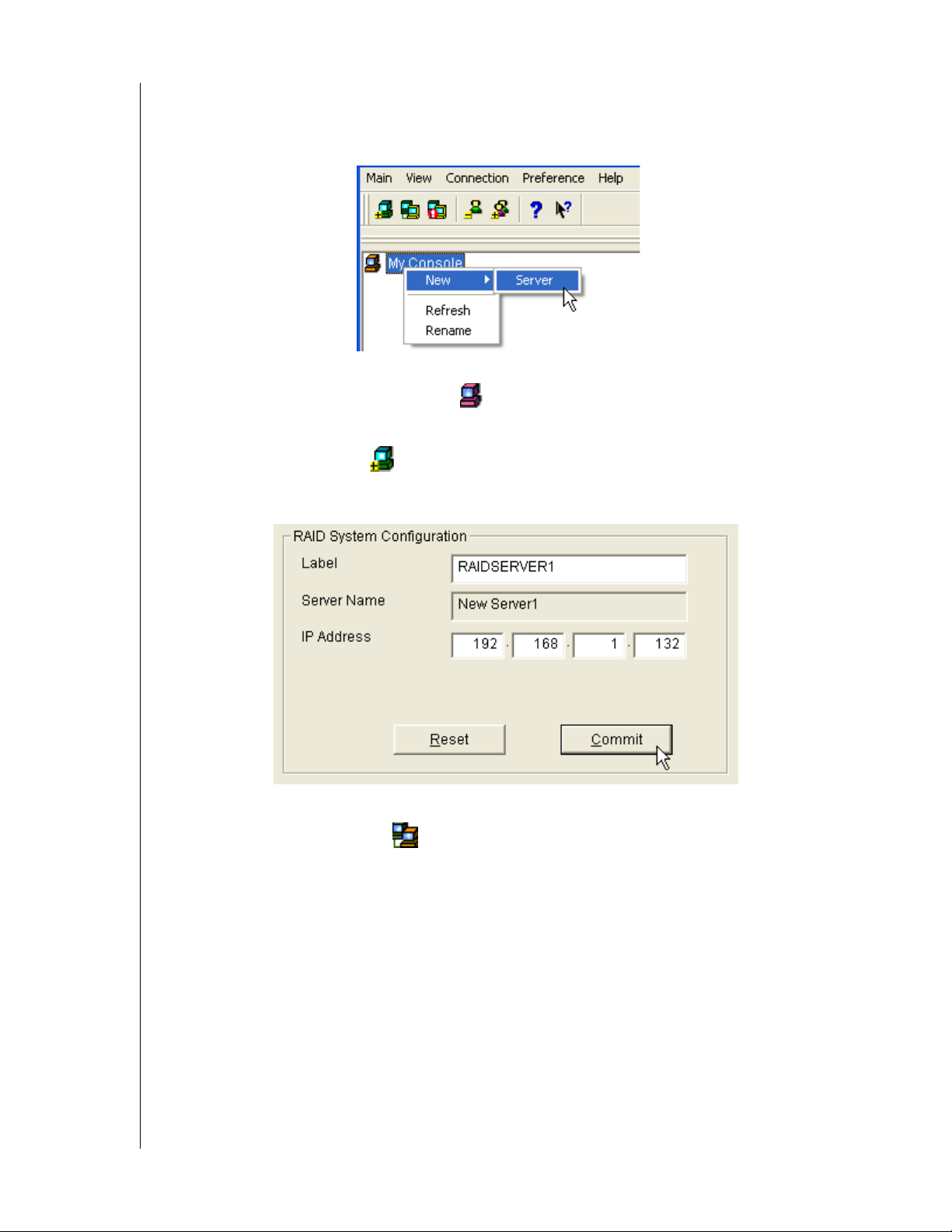
Figure 15. Make a New RAID Server
1. Right-click on the My Console icon and:
-Select New > Server from the popup menu.
- Click the New Server icon in the Toolbar.
A RAID Server icon appears.
Figure 16. RAID System Configuration Box
2. Click on the RAID Server icon. In Information View, type in the IP address of the
computer where the Message Server software is installed.
If the Message Server software in installed on the monitoring PC (the PC you are now
working on), you can use the default 127.0.0.1 IP address.
CHAPTER 3: INITIAL SETUP - 13
Page 18
WD ARRAY MANAGEMENT SETUP
USER MANUAL
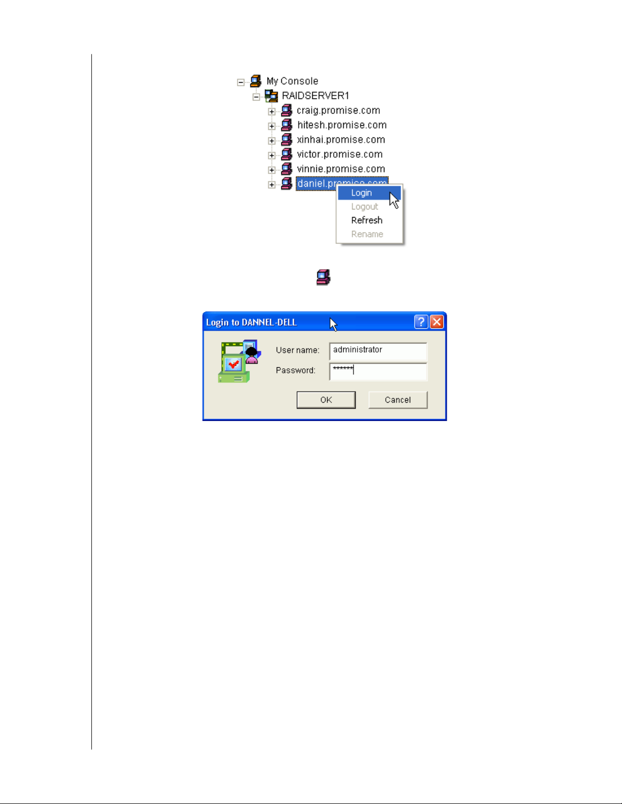
3. Click Commit. A list of networked RAID PCs appears as shown below.
Figure 17. List of Networked RAID PCs
4. Right-click on the RAID Machine icon in Tree View. Select Login from the popup
menu. The Login dialog box appears.
Figure 18. Login Dialog Box
5. In the Login dialog box, type your Username and Password, and click OK.
Initially, administrator is the only user. Use the administrator's password selected during
installation.
If you want to log in to another user's RAID PC, obtain the User name and Password, if
necessary.
CHAPTER 3: INITIAL SETUP - 14
Page 19
WD ARRAY MANAGEMENT SETUP
USER MANUAL
Create a New User
The administrator is created by default. You must create additional users manually.
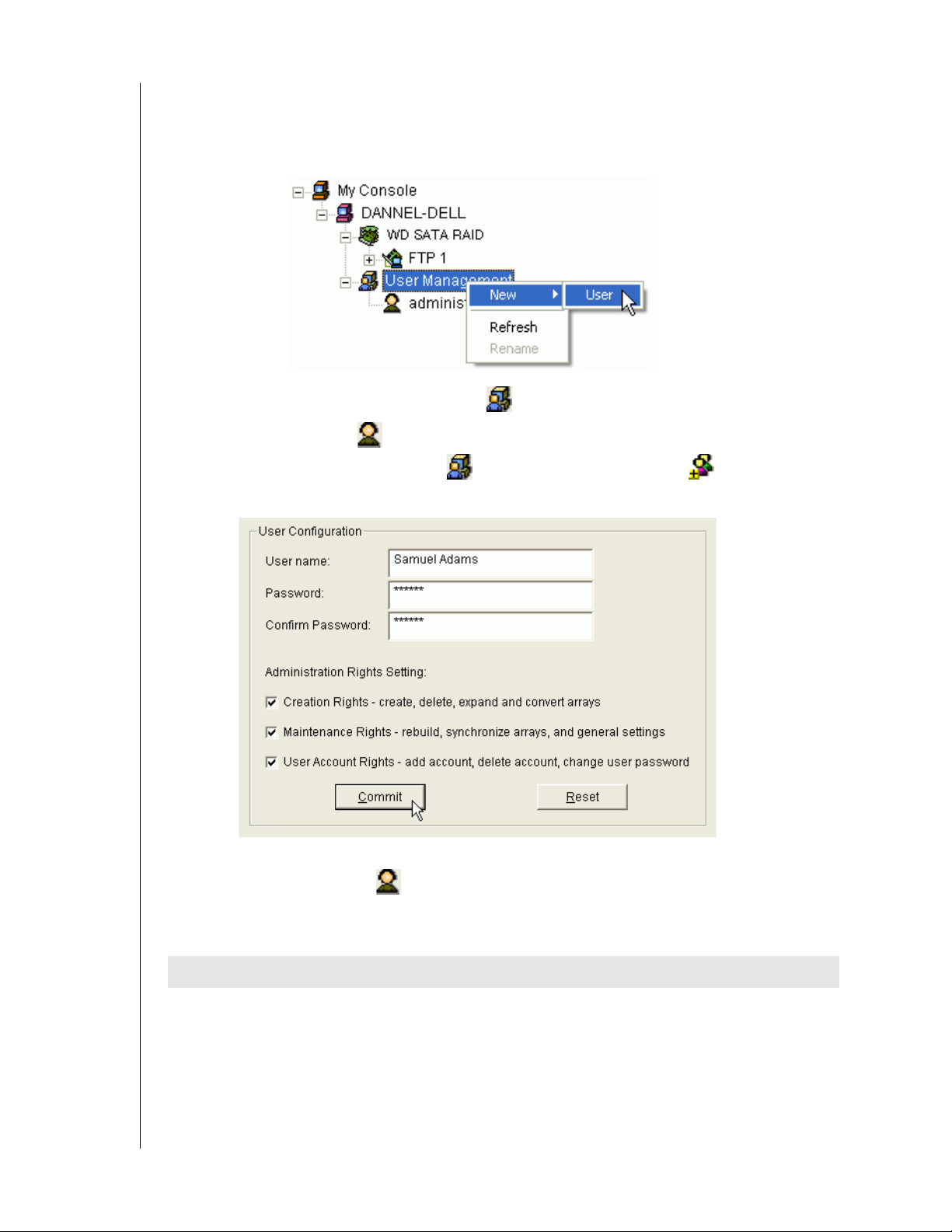
1. Do one of the following:
- Right click on the User Management icon and select New > User from the popup
menu. A new User icon appears.
- Or select the User Management icon and click the Add User button on the
To o l b a r.
Figure 19. User Configuration Box
2. Right-click on the User icon to display the User Information View.
The User Information View displays a request for new user identification and access
rights.
Rights Definition
Creation Allows you to create and delete arrays, rebuild and synchronize arrays, and make
general settings
Maintenance Allows you to rebuild and synchronize arrays, and make general settings
User Account Allows you to add and delete user accounts and change your password
Every User has at least one of these three Rights and can change his/her own password.
CHAPTER 3: INITIAL SETUP - 15
Page 20
WD ARRAY MANAGEMENT SETUP
USER MANUAL
The Administrator can assign more or fewer rights to other Users but cannot change their
passwords.
3. Type a User name and Password in their respective fields.
Check all the appropriate boxes to set access rights. Click the Submit button when you are
done.
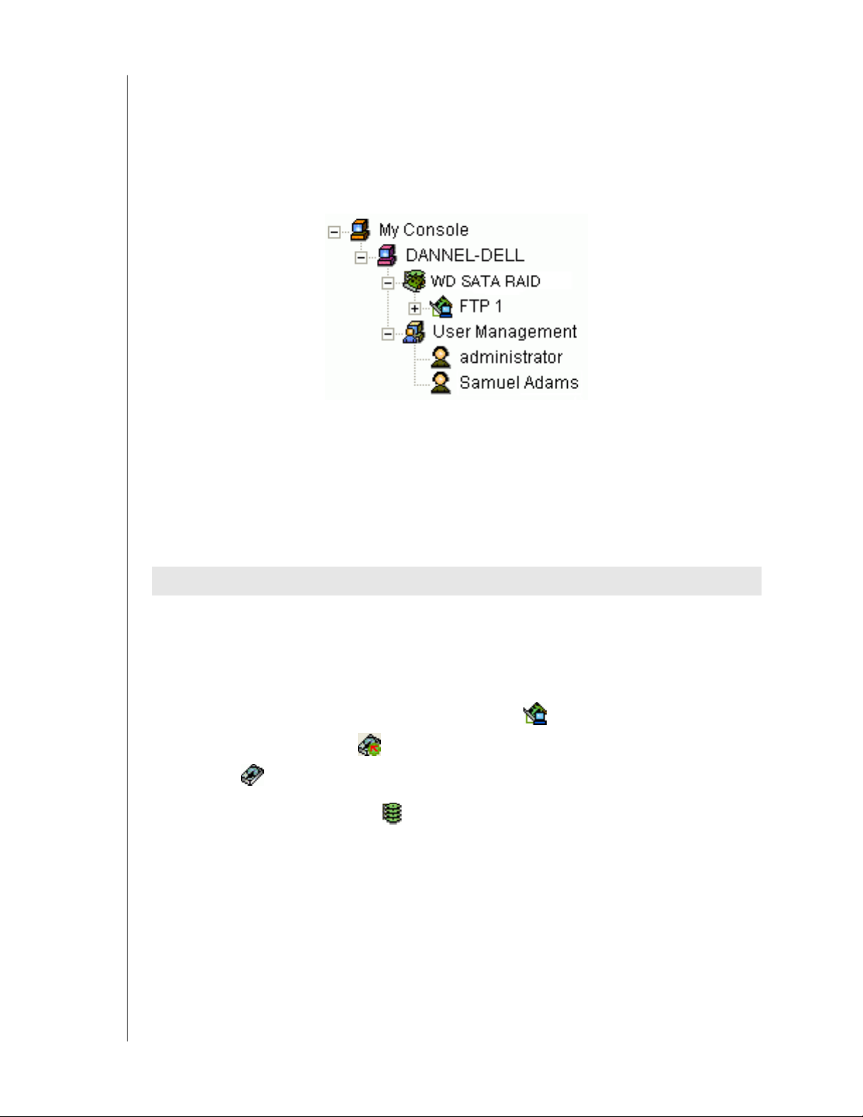
The new user's name appears on Tree View.
Create an Array
The available RAID selection depends on the number of hard drives available.
The table below lists the RAID levels available with WD SATA RAID Controller and the
number of drives required.
See Appendix A: RAID Concepts for a more detailed description.
RAID Level Name Minimum drives Maximum drives
0 Striping 1 4
1 Mirroring 2 2
Table 2. RAID levels available on WD SATA RAID Controller
1. In Tree View, click the + to the left of the Controller icon to see the Disk View icon.
Look under the Disk View icon to see the unassigned disk drives. Unassigned drives
have this icon.
2. Right-click on the Array View icon and select New Array from the popup menu. A
Create Array icon appears.
CHAPTER 3: INITIAL SETUP - 16
Page 21
WD ARRAY MANAGEMENT SETUP
USER MANUAL
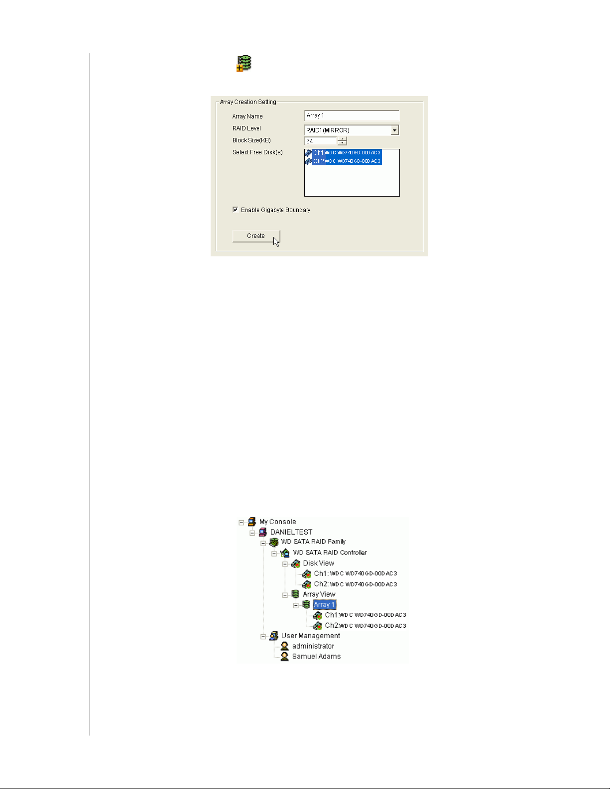
3. Select the Create Array icon and go to the Create Array Settings in Information
View.
Figure 20. Array Creation Setting Box
4. In the Array Creation Settings box:
- Type in a name for your array
- Select the RAID Mode (Level) from the dropdown menu
- Set the Stripe Block Size (see below)
- Highlight the disk drives to add to the array
- Check to enable Gigabyte Boundary, as desired (see below)
Stripe Block Size (RAID 0) - This setting allows you to manually select the stripe block
size. The size selected affects how the WD SATA RAID Controller sends and receives data
blocks to and from the drives. In general, a larger block size is better when handling large
data transfers (such as A/V editing and graphics) while a smaller size is better when
handling email and other common server data. The default is 64 KB. When in doubt, use
the default value.
Gigabyte Boundary (RAID 1) - This setting rounds the size of the array down to the
nearest whole gigabyte. It allows you to install a slightly smaller (within 1 GB)
replacement drive, should the need arise. To enable Gigabyte Boundary, check the box.
5. Click the Create button when you are done.
The new array appears in Tree View.
6. Restart your computer.
CHAPTER 3: INITIAL SETUP - 17
Page 22
WD ARRAY MANAGEMENT SETUP
USER MANUAL
The next step is to partition and format the new array using the RAID PC's operating system.
See Appendix B: Partition and Format for more information.
Setup Alert Notification
AMS alerts you to the problems and processes happening to your RAID through email and
popup messages.
These steps describe how to setup the email function.
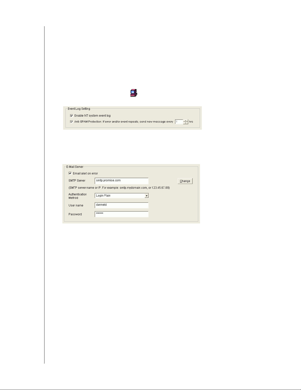
1. Click on the RAID Machine icon. Information for the RAID PC appears in
Information View.
2. Be sure the Enable NT system event log checkbox is checked.
3. To reduce the volume of repeated messages, check the Anti-SAMS checkbox and set an
acceptable time interval in hours.
4. Click on the Email alert on error box, if it is not already checked.
5. In the SMTP server field, type in the SMTP address for your mail server.
6. The default is No Authentication Method. If you want an Authentication Method, in the
dropdown menu choose from:
- CRAM-MD5
- Authorized Login
- Plain Login
7. Type in a User Name and Password in the fields provided.
CHAPTER 3: INITIAL SETUP - 18
Page 23
WD ARRAY MANAGEMENT SETUP
USER MANUAL
8. Click the Change button to update your configuration.
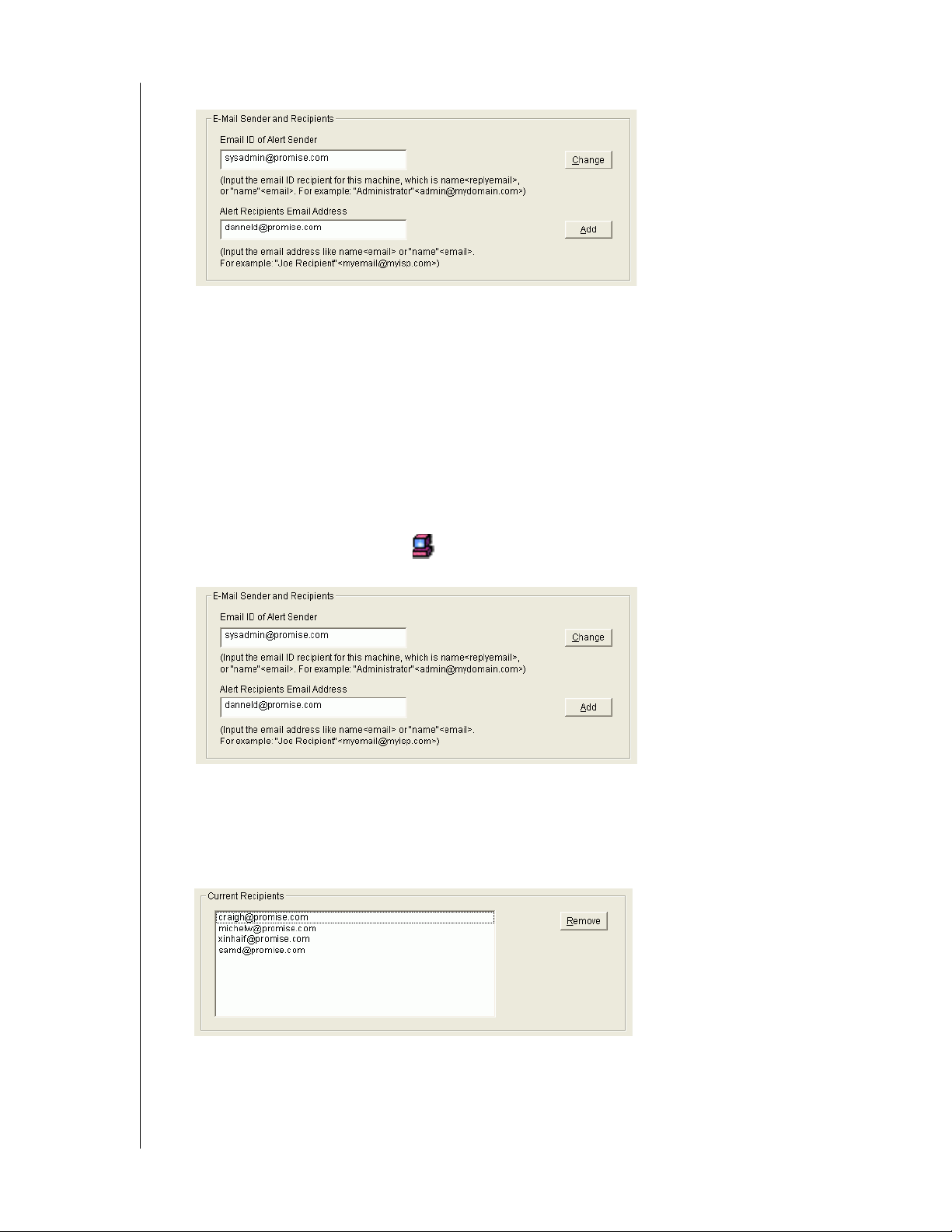
9. Scroll down to the Email Sender and Recipients box.
10. In the Email ID of Alert Sender field, type in the email address of this computer.
11. This address will appear in the From field of the email alerts. Recipients may reply to this
address, if it is valid.
12. Click the Change button to update your configuration.
Add User to Recipient List
After you have setup email alert notification, you must specify who shall receive the alerts.
1. Click on the RAID Machine icon to which you wish to add an email alert message
recipient.
2. In the Alert Recipients Email Address field, type in the email address of the user who you
wish to receive alerts.
3. Click the Add button when you are done. The names appear in the Current Recipients
window.
4. Repeat Step 2 until all addresses have been added.
CHAPTER 3: INITIAL SETUP - 19
Page 24
WD ARRAY MANAGEMENT SETUP
USER MANUAL
Specify Alert Notification Events
AMS can be configured to report a variety of alerts, by email, popup message or both. This
section describes how to tell AMS what to report and which method to use.
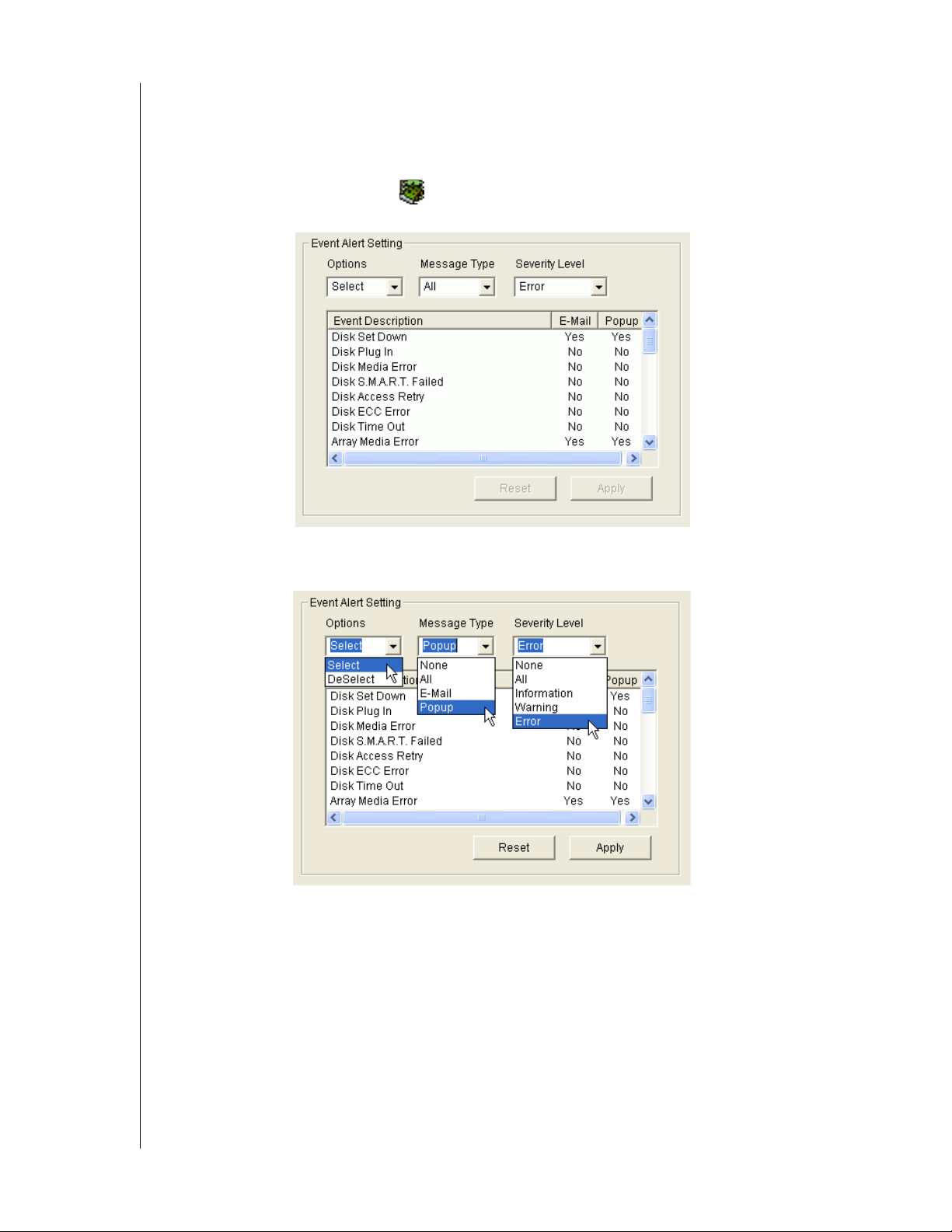
1. Click on the RAID System icon whose alert notification events you wish to modify.
The Event Alert Setting box appears in Information View.
2. The Event Alert Setting box has dropdown menus to help you select Alert Events quickly.
To select Events, click on Options and choose Select.
3. Click on Message Type and choose message delivery by E-Mail, by Popup, by All (both),
or None.
Click on Severity Level and choose Error, War ning , Information, All, or None.
CHAPTER 3: INITIAL SETUP - 20
Page 25

Following is a list of Events and their Severity:
Information Events Warning Events
Disk Plug In Disk Time Out
Disk Access Retry Disk S.M.A.R.T. Failed
Controller Create Array Disk ECC Error
Array Rebuild Started Disk Time Out
Array Auto Rebuild Started Array Critical
Array Rebuild Resumed Controller Delete Array
Array Rebuild Completed Array Rebuild Aborted
Array Synchronization Started Array Rebuild Paused
Array Synchronization Aborted Enclosure Over Temperature
Array Synchronization Paused Enclosure Fan Stop
Array Synchronization Resumed Enclosure 12V Error
Array Synchronization Completed Enclosure 5V Error
Enclosure Power Up Enclosure 3.3V Error
Enclosure Power Down
Error Events
Disk Offline
Array Media Error
Array Offline
Array Rebuild Failed
Array Synchronization Failed
Array Synchronization Comparison Error
WD ARRAY MANAGEMENT SETUP
USER MANUAL
4. To select an individual Event, click in the E-Mail and Popup columns to toggle between
Yes and No.
5. When you are finished, click the Apply button.
CHAPTER 3: INITIAL SETUP - 21
Page 26
WD ARRAY MANAGEMENT SETUP
USER MANUAL
Chapter 4: AMS User Interface
This chapter describes AMS's Graphic User Interface (GUI). AMS adds a graphic user
interface to make RAID management functions easier to understand and perform.
Figure 21. The AMS Monitor Window Has Three Views
CHAPTER 4: AMS USER INTERFACE - 22
Page 27
WD ARRAY MANAGEMENT SETUP
USER MANUAL
Tree View
Local AMS
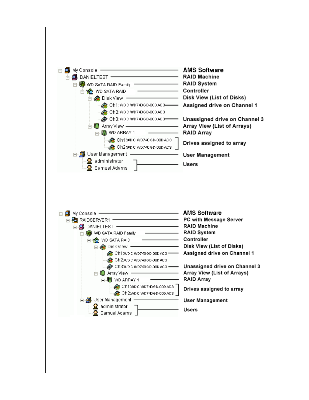
The Tree View displays all of the elements of your RAID system. Use it to navigate to specific
components.
Figure 22. An example of a Local AMS RAID system in Tree View
Remote AMS
Remote AMS adds a RAID Server icon to connect with the Message Server PC to monitor
arrays over a network.
Figure 23. An example of a Remote AMS RAID system in Tree View
Normally, the Tree View is present. To close it, right-click on any object and select Hide Pane
from the popup menu.
To open it again, go to View menu and select Outline.
CHAPTER 4: AMS USER INTERFACE - 23
Page 28
WD ARRAY MANAGEMENT SETUP
USER MANUAL
Tree View and Component Specific Menus
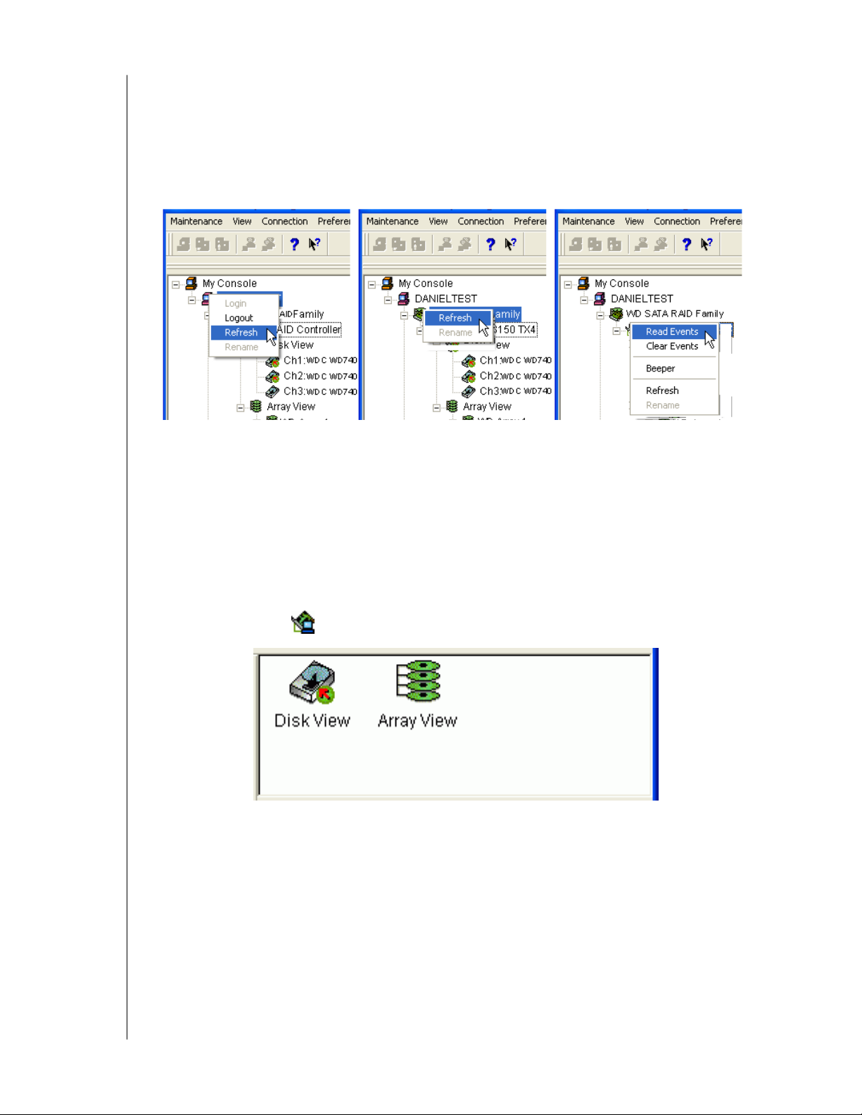
In AMS, like most Windows applications, you can access the various commands and
functions by opening dropdown menus and clicking on icons. Each time you click on a
component in Tree View, AMS's menu bar also displays that component's dropdown menu.
Below are some examples.
Figure 24. Each item in Tree View has its own dropdown menu in the menu bar
Rather than access the menu bar, you can right click on the icon of the component you are
working with. The menu bar and popup menus for Tree View items are identical.
Object View
Object View is visible whenever the Tree View is visible. The items appearing in Object View
are determined by which component you select in Tree View. In the example below, we
selected a Controller icon in Tree View.
Figure 25. Object View of a Controller's components
As a result, you see the components of that Controller, in this case, six channels, an enclosure
and an array. This feature makes it easy to find an individual component as well as see what
items are assigned to higher level components. Double-click on these items to see their
components in Object View and their configuration in Information View.
CHAPTER 4: AMS USER INTERFACE - 24
Page 29
WD ARRAY MANAGEMENT SETUP
USER MANUAL
Information View
Information View, like Object View, changes its content depending on which item you select
in Tree View. The difference is that you use Information View to obtain data, input settings
and information.
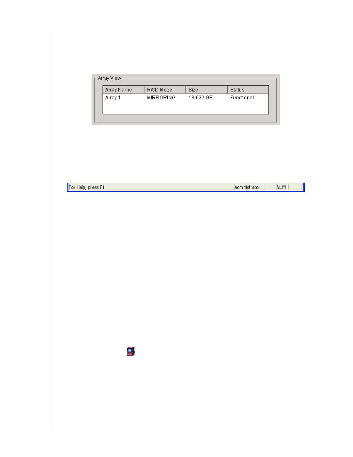
Figure 26. Information View showing part of the setup for an Array
Status Bar
The AMS Status Bar is the same as other Windows applications. It indicates such things as the
selected RAID is rebuilding, and the current user is the Administrator (shown below).
Figure 27. AMS Status Bar.
Normally the Status Bar is visible. To show or hide the Status Bar, go to the View menu and
check or uncheck Status Bar.
Pulldown Menus
The left-most Pulldown Menu changes according to which component is selected in the Tree
View.
This menu can be the Main, My Console, Server, RAID Machine, RAID System or
Maintenance.
The functions of each menu are described below.
Main Menu
When no item in Tree View is selected, the left-most menu item is Main. Its only function is
Exit, which quits the AMS application.
My Console Menu
When the My Console icon is selected, the My Console menu appears. Its functions
include:
! Create a new Server
! Screen refresh
! Rename the My Console icon
! Exit AMS
CHAPTER 4: AMS USER INTERFACE - 25
Page 30
WD ARRAY MANAGEMENT SETUP
USER MANUAL
Server Menu
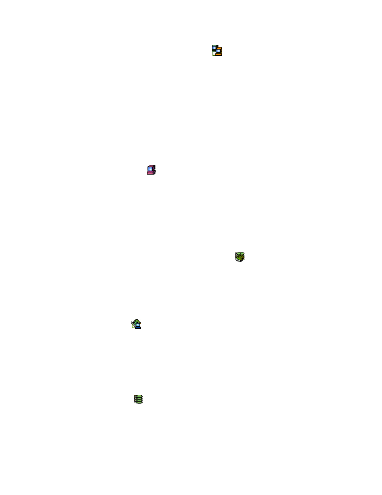
The Server menu appears when the RAID Server icon is selected.
This menu applies only to Remote AMS. Its functions include:
! Modify the connection
! Delete the connection
! Connect
! Disconnect
! Screen refresh
! Rename the Server icon
! Exit AMS
RAID Machine Menu
When the RAID Machine is selected, the RAID Machine menu appears. Its functions
include:
! Login
! Logout
! Screen refresh
! Exit AMS
RAID System Menu
The RAID System menu appears with the RAID System icon is selected. Its functions
include:
! Screen refresh
! Exit AMS
Maintenance Menu
When the Controller icon is selected, the Maintenance menu displays Controller
functions:
! Read Events in the Event Viewer
! Clear Events from the Event Viewer
! Toggle the Beeper on and off
! Refresh the screen
! Exit AMS
When the Array View icon is selected, the Maintenance menu displays Controller
functions:
! Create an array
! Refresh the screen
! Rename the Array icon
CHAPTER 4: AMS USER INTERFACE - 26
Page 31

WD ARRAY MANAGEMENT SETUP
USER MANUAL
View Menu
The View menu is always the same. It displays or hides three items:
! Toolbar
! Status Bar
! Tree View (Outline)
Check to display or uncheck to hide each one as you prefer.
Connection Menu
The Connection menu is always the same. It deals with server connections. Use it to:
! Create a new Message Server
! Connect to a RAID Server
! Disconnect from a RAID server
Preference Menu
The Preference menu is always the same. It allows you to start AMS automatically when your
PC boots.
Check to enable or uncheck to disable this feature.
If you are using AMS for remote monitoring, running AMS automatically is a good idea.
This way, your PC will be connected to the RAID and you will receive all the alerts messages
you have specified.
Help Menu
The Help menu is always the same. Under Help, AMS has:
! Full online Help file
! Auto Demo display
! About page with AMS information
CHAPTER 4: AMS USER INTERFACE - 27
Page 32
WD ARRAY MANAGEMENT SETUP
USER MANUAL
Toolbar
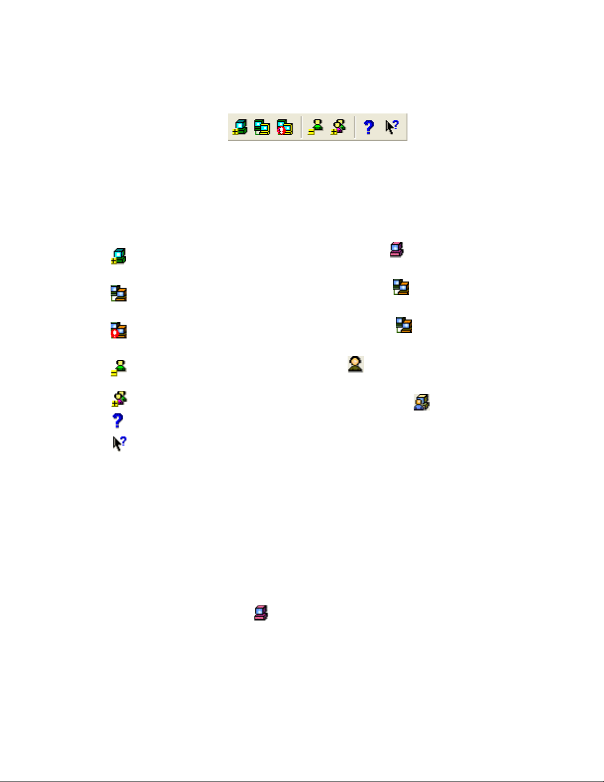
The Toolbar is a series of buttons that are shortcuts to performing specific tasks. You will
never see all buttons active as in the example below.
Figure 28. The Toolbar
They become active when you click on specific system components in Tree View. Only the
tool buttons pertaining to that component are active.
Most of these functions require User Account Rights. These are specified when a User is
added or modified. Following is a description of the Toolbar buttons:
New Server. Available when you select the MyConsole icon in Remote AMS.
Creates a new Message Server.
Connect. Available when you select the Message Server icon in Remote AMS.
Initiates a connection with the RAID Server.
Disconnect. Available when you select a Message Server icon. Disconnects from
the RAID Server. Used when you want to shut down a RAID server for repair.
Delete User. Available when you select a User icon. Deletes the user from
monitoring and alert access.
New User. Available when you select the User Management icon.
About. Brings up the information about this version of AMS.
Help. Always available. Brings up the Online Help.
Popup Menus
In addition to the commands in the dropdown menus, there is a corresponding set of
commands you can access via popup menus.
In a popup menu, you can use any of the commands that are in black.
You will notice that some functions are grayed out, meaning that you cannot use them.
Many functions require that you have User Account Rights to perform them.
My Console Icon
Right-click on the My Console icon to access the following commands:
! New Server (Remote AMS)
! Screen refresh
! Rename the My Console icon
CHAPTER 4: AMS USER INTERFACE - 28
Page 33
WD ARRAY MANAGEMENT SETUP
Message Server Icon
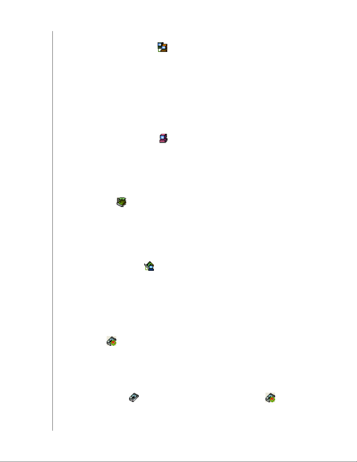
Right-click on the Message Server icon to access the following commands:
! Modify the connection
! Delete the connection
! Connect
! Disconnect
! Screen refresh
! Rename the Message Server icon
RAID Machine Icon
Right-click on the RAID Machine icon to access the following commands:
! Login
! Logout
! Screen refresh
USER MANUAL
RAID System Icon
The RAID System icon represents the WD SATA RAID Controller.
There are two commands for this item.
• Refresh the screen
• Disk Icon
Controller Icon
Right-click on the Controller icon to access the following commands:
! Read Events in the Event Viewer
! Clear Events from the Event Viewer
! Toggle the Beeper on and off
! Refresh the screen
Disk View Icon
The Disk View icon represents an individual channel on the WD SATA RAID
Controller.
There are two commands for this item.
• Refresh the screen
• Disk Icon
Right-click on the Disk icon of an unassigned drive or the Disk View icon of an
assigned drive to access the following command:
• Refresh the screen
CHAPTER 4: AMS USER INTERFACE - 29
Page 34
WD ARRAY MANAGEMENT SETUP
Array View Icon
Right-click on the Array View icon to access the following commands:
! Synchronize this array
! Delete this array
! Pause synchronization/rebuild
! Continue synchronization/rebuild
! Refresh the screen
! Rename the Array
User Management Icon
Right-click on the User Management icon to access the following commands:
! Create a New User
! Refresh the screen
! User Icon
USER MANUAL
Right-click the User icon to access the following commands:
! Delete this User
! Refresh the screen
CHAPTER 4: AMS USER INTERFACE - 30
Page 35
WD ARRAY MANAGEMENT SETUP
USER MANUAL
Chapter 5: RAID Monitoring and Maintenance with AMS
This chapter describes using AMS to monitor and manage your RAID system. The chapter is
divided into sections for as follows:
! Remote AMS
! Local AMS
! User Management
! Alert Notification
! Controller
! Arrays
Remote AMS
Create a RAID Server
Remote AMS works over your network. Therefore it requires additional steps the first time
you log on. Launch Remote AMS. When the AMS user interface appears:
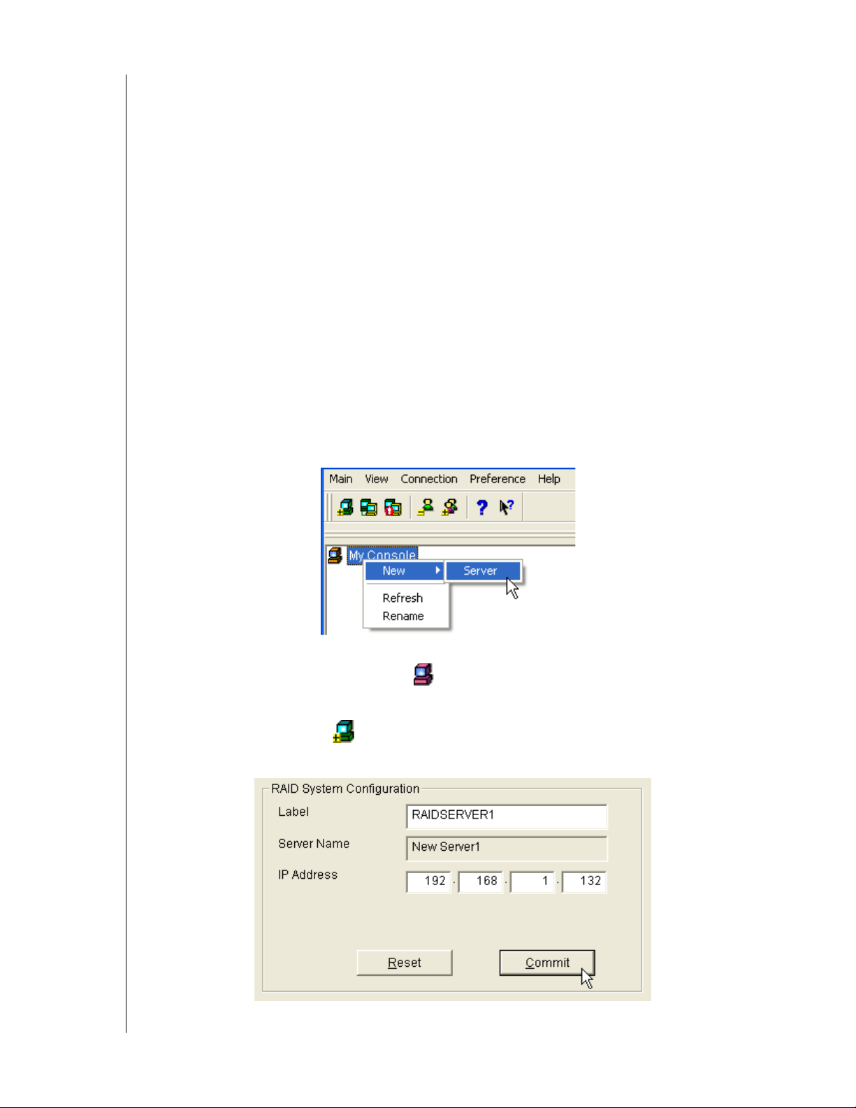
Figure 29. Make a New RAID Server
1. Right-click on the My Console icon and:
-Select New > Server from the popup menu.
- Click the New Server icon in the Toolbar.
A RAID Server icon appears.
Figure 30. RAID System Configuration Box
CHAPTER 5: RAID MONITORING AND MAINTENANCE WITH AMS - 31
Page 36
WD ARRAY MANAGEMENT SETUP
USER MANUAL
2. Click on the RAID Server icon. In Information View, type in the IP address of the
computer where the Message Server Software is installed.
If the Message Server software in installed on the monitoring PC (the PC you are now
working on), you can use the default 127.0.0.1 IP address.
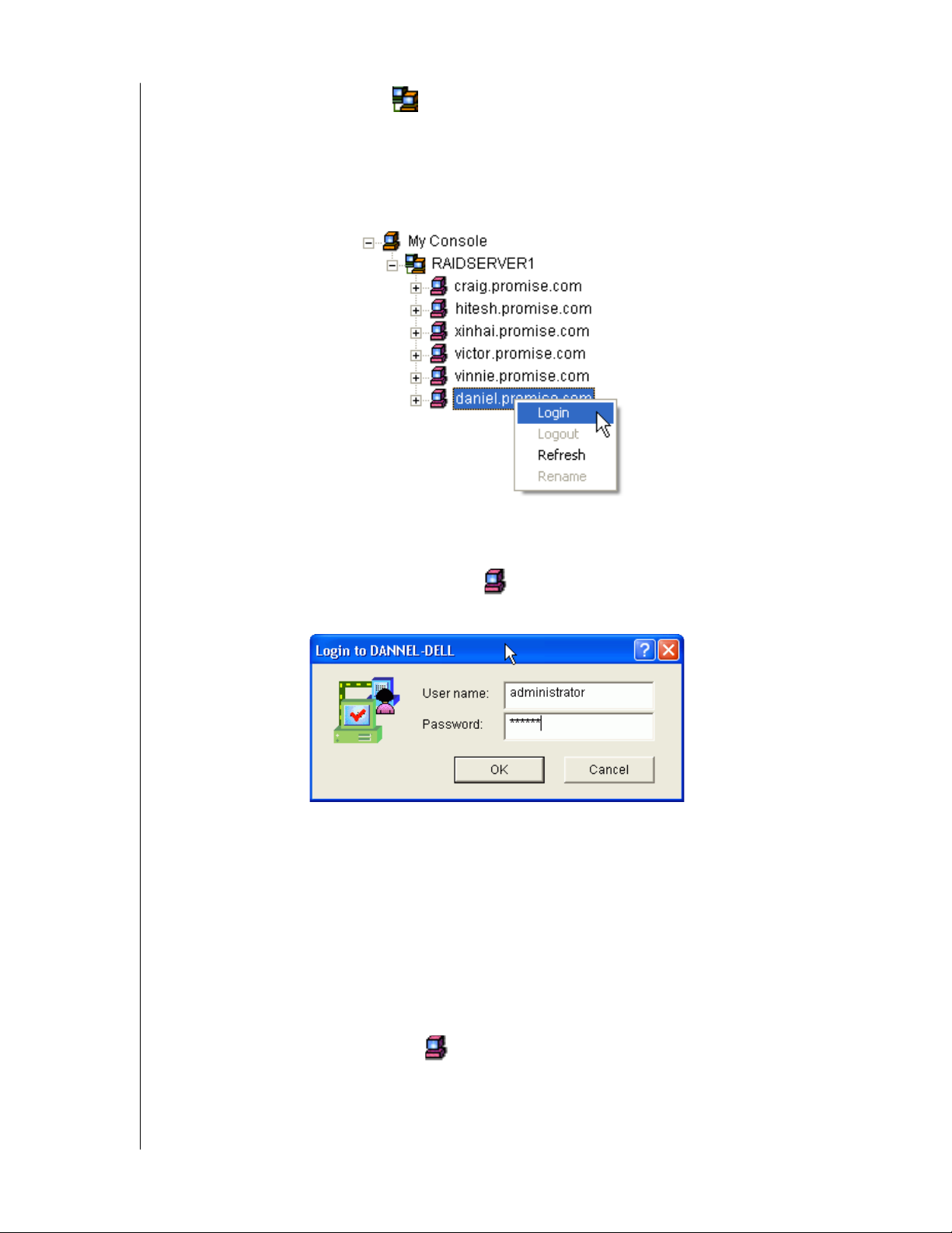
3. Click Commit. A list of networked RAID PCs appears as shown below.
Figure 31. List of Networked RAID PCs
Login to RAID PC
1. Right-click on the RAID Machine icon in Tree View. Select Login from the popup
menu. The Login dialog box appears.
Figure 32. Login Dialog Box
2. In the Login dialog box, type your Username and Password, and click OK.
Initially, administrator is the only user. Use the administrator's password selected during
installation.
3. If you want to log in to another user's RAID PC, obtain the User name and Password if
necessary.
Log Out of RAID PC
You can log out of one RAID PC while remaining connected to others on the network.
Right-click on the RAID Machine icon of the PC you want to disconnect and select
Logout from the popup menu.
CHAPTER 5: RAID MONITORING AND MAINTENANCE WITH AMS - 32
Page 37
WD ARRAY MANAGEMENT SETUP
USER MANUAL
Disconnect from RAID Server
Log out of the RAID Server effectively logs you out of all RAID PCs using that network
connection.
To disconnect from the network:
• Right-click on a RAID Server icon and select Disconnect from the popup menu.
Future Connections to RAID Server
The RAID Server remains under the My Console icon until deleted. It continues to work as
long as the IP address is correct.
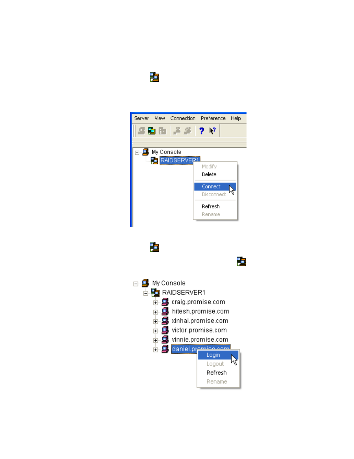
To make a connection with an existing RAID Server:
• Right-click on a RAID Server icon and select Connect from the popup menu.
• Or right-click on the RAID Server icon and click the Connect icon in the Toolbar.
The Login list of networked RAID PCs appears as before.
Figure 33. List of networked RAID PCs
Log into a RAID PC as described above.
CHAPTER 5: RAID MONITORING AND MAINTENANCE WITH AMS - 33
Page 38
WD ARRAY MANAGEMENT SETUP
USER MANUAL
Message Server IP Address Change
If the IP address changes for the computer where the Message Server software is installed, an
existing RAID Server with the old address will no longer work.
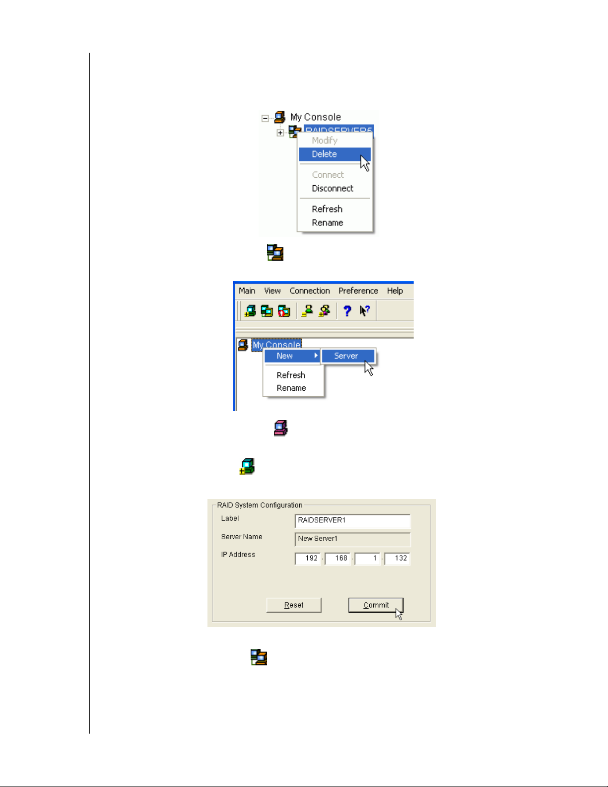
1. Right-click on a RAID Server icon and select Delete from the popup menu.
2. Click OK in the confirmation dialog box.
3. Right-click on the My Console icon and:
-Select New > Server from the popup menu.
- Click the New Server icon in the Toolbar.
A RAID Server icon appears.
Figure 34. RAID System Configuration box
4. Click on the RAID Server icon. In Information View, type in the IP address of the
computer where the Message Server Software is installed.
If the Message Server software in installed on the monitoring PC (the PC you are now
working on), you can use the default 127.0.0.1 IP address.
CHAPTER 5: RAID MONITORING AND MAINTENANCE WITH AMS - 34
Page 39
WD ARRAY MANAGEMENT SETUP
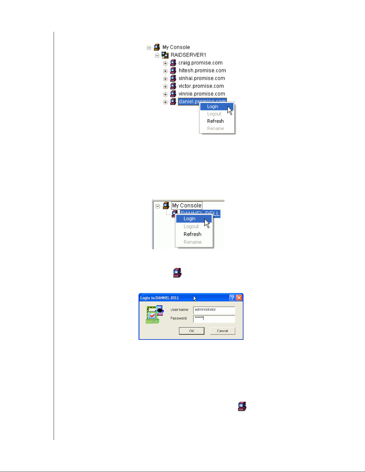
5. Click Commit. A list of networked RAID PCs appears as shown below.
Figure 35. List of networked RAID PCs
Local AMS
Log In
Launch Local AMS. When the AMS user interface appears:
USER MANUAL
Figure 36. Log in to Local AMS
1. Right click on the RAID Machine icon in Tree View. Select Login from the popup
menu. The Login dialog box appears.
Figure 37. Login dialog box
2. In the Login dialog box, type your Username and Password, and click OK.
Initially, administrator is the only user. Use the administrator's password selected during
installation.
Log Out
To log out of a Local AMS, right-click on the RAID Machine icon and select Logout
from the popup menu.
CHAPTER 5: RAID MONITORING AND MAINTENANCE WITH AMS - 35
Page 40
WD ARRAY MANAGEMENT SETUP
USER MANUAL
User Management
Create a User
The administrator is created by default. You must create additional users manually.
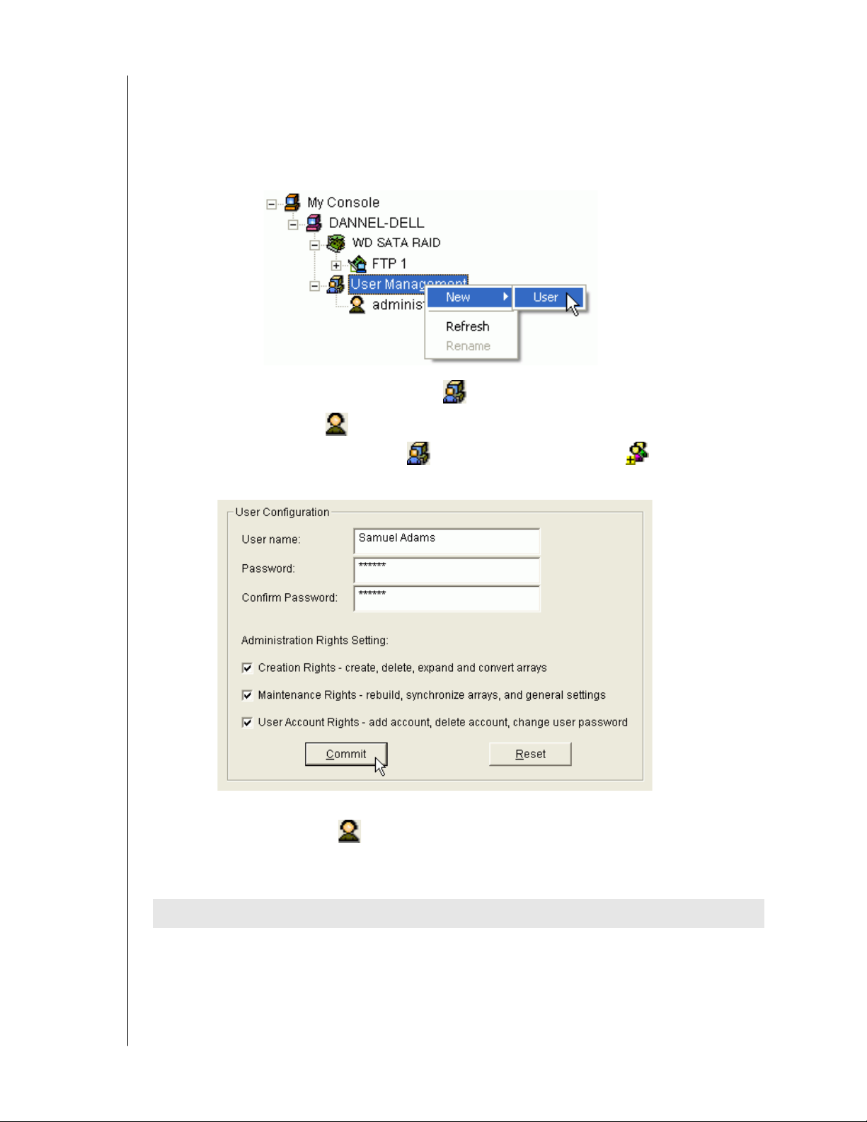
1. Do one of the following:
- Right click on the User Management icon and select New > User from the popup
menu. A new User icon appears.
- Or select the User Management icon and click the Add User button on the
To o l b a r.
Figure 38. User Configuration Box
2. Right-click on the User icon to display the User Information View.
The User Information View displays a request for new user identification and access
rights.
Rights Definition
Creation Allows you to create and delete arrays, rebuild and synchronize arrays, and make
general settings
Maintenance Allows you to rebuild and synchronize arrays, and make general settings
User Account Allows you to add and delete user accounts and change your password
CHAPTER 5: RAID MONITORING AND MAINTENANCE WITH AMS - 36
Page 41
WD ARRAY MANAGEMENT SETUP
USER MANUAL
Every User has at least one of these three Rights and can change his/her own password.
The Administrator can assign more or fewer rights to other Users but cannot change their
passwords.
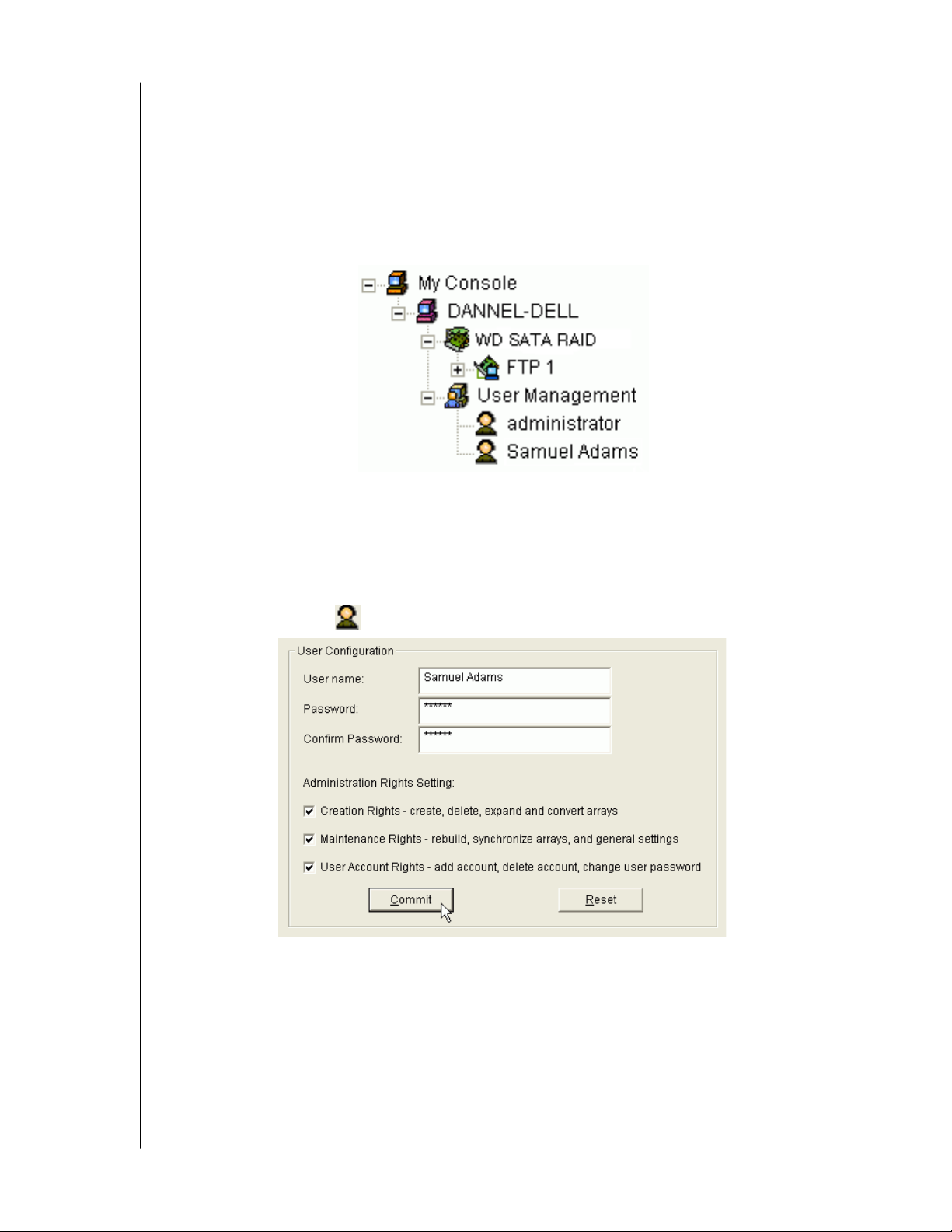
3. Type a User name and Password in their respective fields.
Check all the appropriate boxes to set access rights. Click the Submit button when you are
done.
The new user's name appears on Tree View.
Change Password
Every User can change his/her own password.
The Administrator cannot change other Users' passwords.
1. Log in to AMS under the User Name whose Password you want to change.
2. Click on the User icon of the User whose Password you want to change.
3. In Information View, type in a new Password in the two Password fields.
4. Click the Submit button when you are done.
CHAPTER 5: RAID MONITORING AND MAINTENANCE WITH AMS - 37
Page 42
WD ARRAY MANAGEMENT SETUP
USER MANUAL
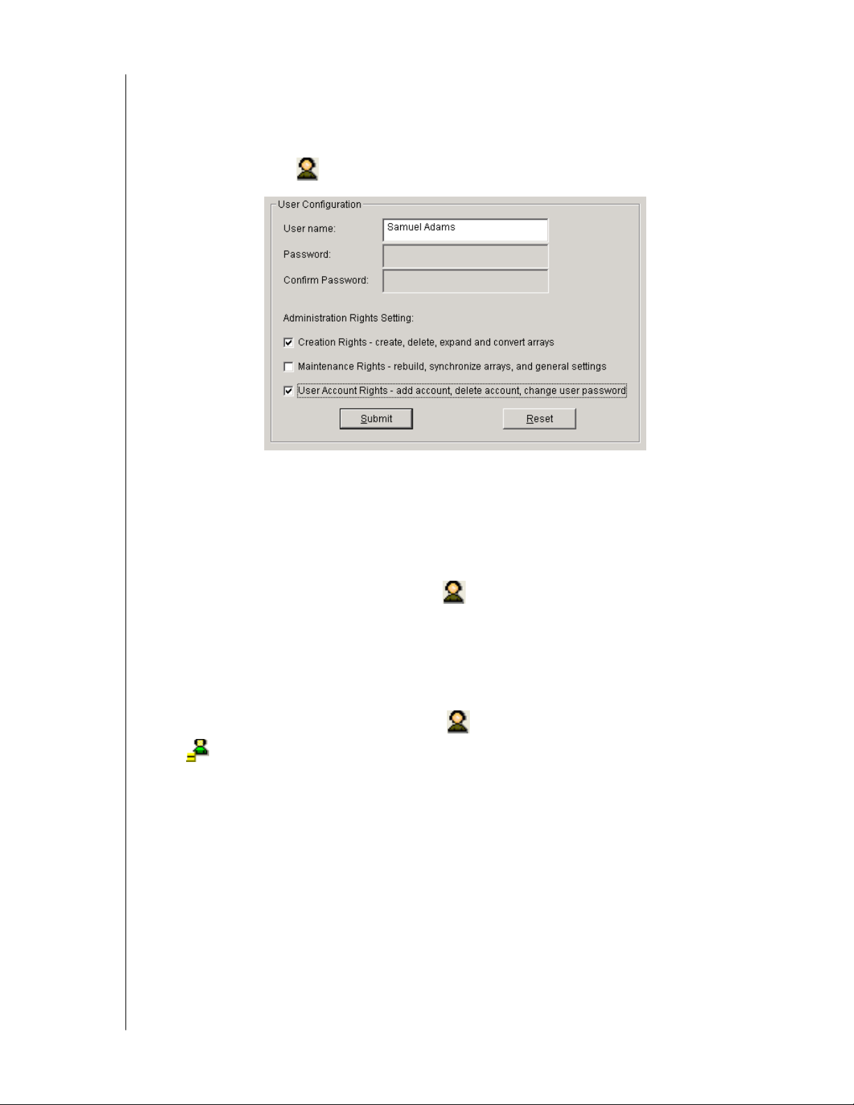
Change User Rights
The Administrator can change any User's Rights. Other Users cannot change their Rights.
1. Log into AMS as the Administrator.
2. Click on the User icon of the User whose Rights you want to change.
3. In Information View, check or uncheck Rights options as desired (above).
4. Click the Submit button when you are done.
Delete a User
1. In the Tree View, right-click on the User icon of the User you wish to delete and
select Delete from the popup menu.
2. In the confirmation dialog box, click OK.
Note: AMS will always keep one user account with access rights, typically the
Administrator. This action protects you from being locked out of the system.
Another way to delete a User: Select the User icon in Tree View then click the Delete
User icon in the Toolbar.
CHAPTER 5: RAID MONITORING AND MAINTENANCE WITH AMS - 38
Page 43
WD ARRAY MANAGEMENT SETUP
USER MANUAL
Alert Notification
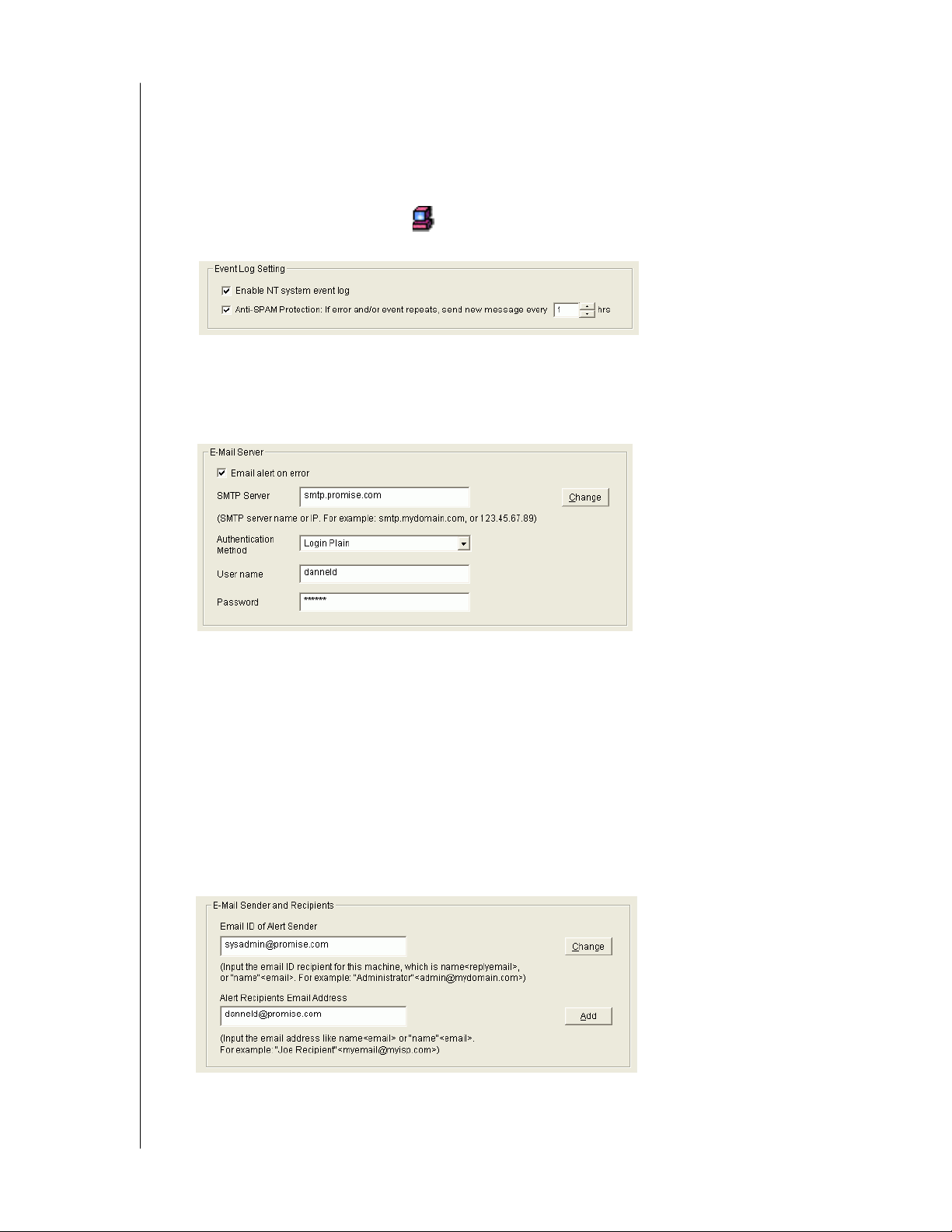
AMS alerts you to the problems and processes happening to your RAID through email and
popup messages.
These steps describe how to setup the email function.
1. Click on the RAID Machine icon. Information for the RAID PC appears in
Information View.
2. Be sure the Enable NT system event log checkbox is checked.
3. To reduce the volume of repeated messages, check the Anti-SAMS checkbox and set an
acceptable time interval in hours.
4. Click on the Email alert on error box, if it is not already checked.
5. In the SMTP server field, type in the SMTP address for your mail server.
6. The default is No Authentication Method. If you want an Authentication Method, in the
dropdown menu choose from:
- CRAM-MD5
- Authorized Login
- Plain Login
7. Type in a User Name and Password in the fields provided.
8. Click the Change button to update your configuration.
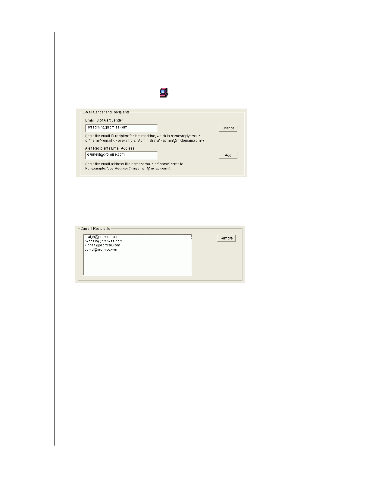
9. Scroll down to the Email Sender and Recipients box.
10. In the Email ID of Alert Sender field, type in the email address of this computer.
CHAPTER 5: RAID MONITORING AND MAINTENANCE WITH AMS - 39
Page 44
WD ARRAY MANAGEMENT SETUP
USER MANUAL
11. This address will appear in the From field of the email alerts. Recipients may reply to this
address if it is valid.
12. Click the Change button to update your configuration.
Add User to Recipient List
After you have set up email alert notification, you must specify who shall receive the alerts.
1. Click on the RAID Machine icon to which you wish to add an email alert message
recipient.
2. In the Alert Recipients Email Address field, type in the email address of the user who you
wish to receive alerts.
3. Click the Add button when you are done. The names appear in the Current Recipients
window.
4. Repeat Step 2 until all addresses have been added.
CHAPTER 5: RAID MONITORING AND MAINTENANCE WITH AMS - 40
Page 45
WD ARRAY MANAGEMENT SETUP
USER MANUAL
Specify Alert Notification Events
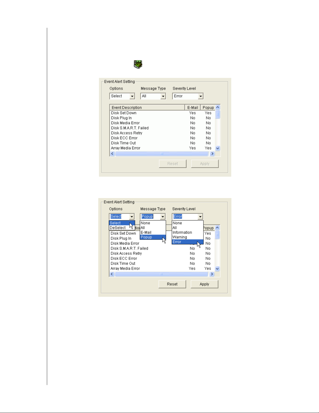
AMS can be configured to report a variety of alerts, by email, popup message, or both. This
section describes how to tell AMS what to report and which method to use.
1. Click on the RAID System icon whose alert notification events you wish to modify.
The Event Alert Setting box appears in Information View.
2. The Event Alert Setting box has dropdown menus to help you select Alert Events quickly.
To select Events, click on Options and choose Select.
3. Click on Message Type and choose message delivery by E-Mail, by Popup, by All (both),
or None.
4. Click on Severity Level and choose Error, Warn ing , Information, All, or None.
CHAPTER 5: RAID MONITORING AND MAINTENANCE WITH AMS - 41
Page 46

Following is a list of events and their severity:
Information Events Warning Events
Disk Plug In Disk Time Out
Disk Access Retry Disk S.M.A.R.T. Failed
Controller Create Array Disk ECC Error
Array Rebuild Started Disk Time Out
Array Auto Rebuild Started Array Critical
Array Rebuild Resumed Controller Delete Array
Array Rebuild Completed Array Rebuild Aborted
Array Synchronization Started Array Rebuild Paused
Array Synchronization Aborted Enclosure Over Temperature
Array Synchronization Paused Enclosure Fan Stop
Array Synchronization Resumed Enclosure 12V Error
Array Synchronization Completed Enclosure 5V Error
Enclosure Power Up Enclosure 3.3V Error
Enclosure Power Down
Error Events
Disk Offline
Array Media Error
Array Offline
Array Rebuild Failed
Array Synchronization Failed
Array Synchronization Comparison Error
WD ARRAY MANAGEMENT SETUP
USER MANUAL
5. To select an individual Event, click in the E-Mail and Popup columns to toggle between
Yes and No.
6. When you are finished, click the Apply button.
CHAPTER 5: RAID MONITORING AND MAINTENANCE WITH AMS - 42
Page 47
WD ARRAY MANAGEMENT SETUP
USER MANUAL
Controller
Options
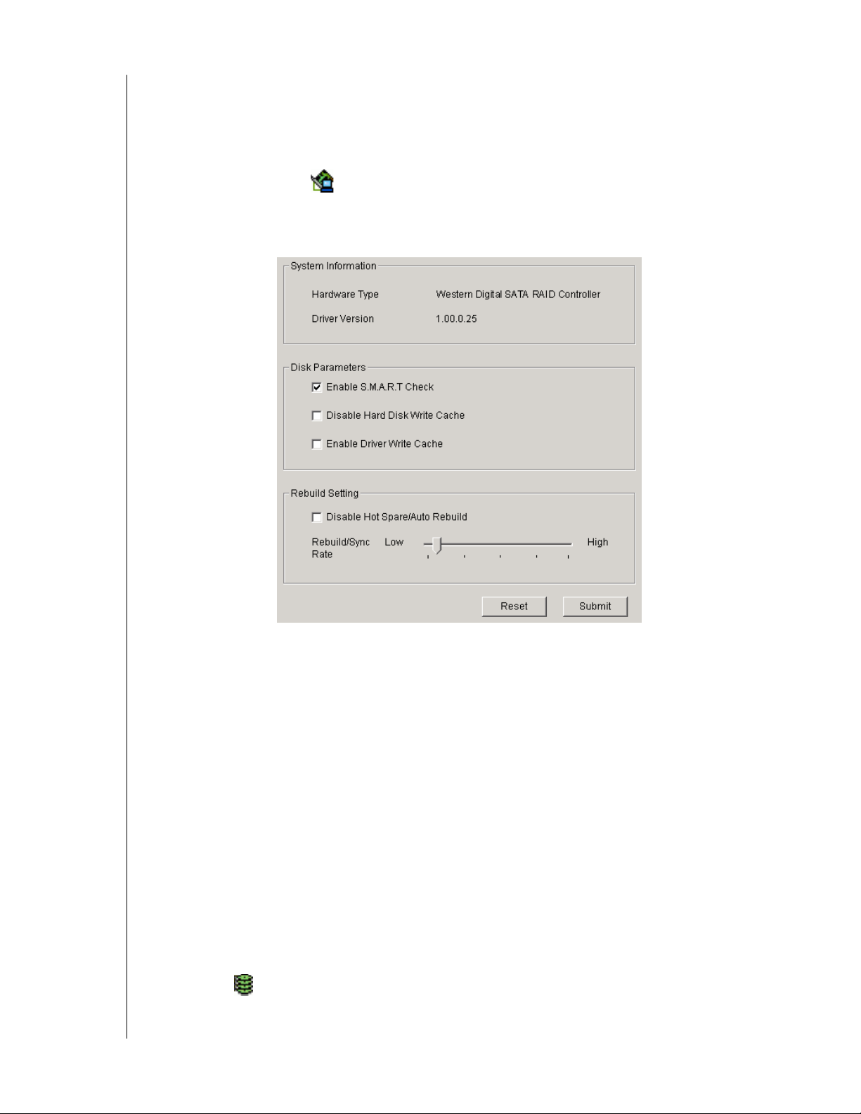
The Controller has system information and settings several important features.
Click on the Controller icon in Tree View to see the Options in Information View.
To return to the previous settings, click Reset.
To Apply the changes you have made, click Submit.
System Information
This describes the Controller type, in this case a WD SATA RAID Controller and the driver.
This information may be helpful when upgrading your WD SATA RAID Controller or
troubleshooting the PC.
Disk Parameters
Check the respective boxes to enable these features:
SMART Check - SMART, an acronym for Self-Monitoring Analysis and Reporting
Technology, is a feature of the disk drive software. It monitors the internal performance of the
drive and reports to the PC when it finds a potential failure. SMART warns you of a
developing drive failure so you can replace the drive before it actually fails.
Disable Hard Disk Write Cache - Disables the Write Cache on the hard disk drives. This
action will reduce performance unless you enable the Driver (WD SATA RAID Controller)
Write Cache.
Enable Driver Write Cache - Speeds hard disk performance by writing data to the cache on
the WD SATA RAID Controller. When you are done setting controller options, click on the
Array View icon and choose between Write Back and Write Though cache settings (see
below).
CHAPTER 5: RAID MONITORING AND MAINTENANCE WITH AMS - 43
Page 48
WD ARRAY MANAGEMENT SETUP
Rebuild Setting
USER MANUAL
Check the respective boxes to enable these features:
Disable Hot Spare/Auto Rebuild - Disables automatic rebuilding using a hot spare drive or a
newly installed replacement drive. With this option checked, you must initiate rebuilding
manually. See RAID 1 (Mirroring) and Hot Spare Drive.
Rebuild/Sync Rate - Allocates system resources between rebuilding the array and responding
to read/write commands from the computer system.
A High setting assigns most of the system resources to a rebuild or synchronization of the
array. The process will finished sooner but read/write requests are handled slower.
A Low setting assigns most of the system resources to handling read/write requests. Read/
write requests are handled at nearly normal speed while the rebuild or synchronization takes
longer.
See Rebuild an Array for more information on the rebuilding process.
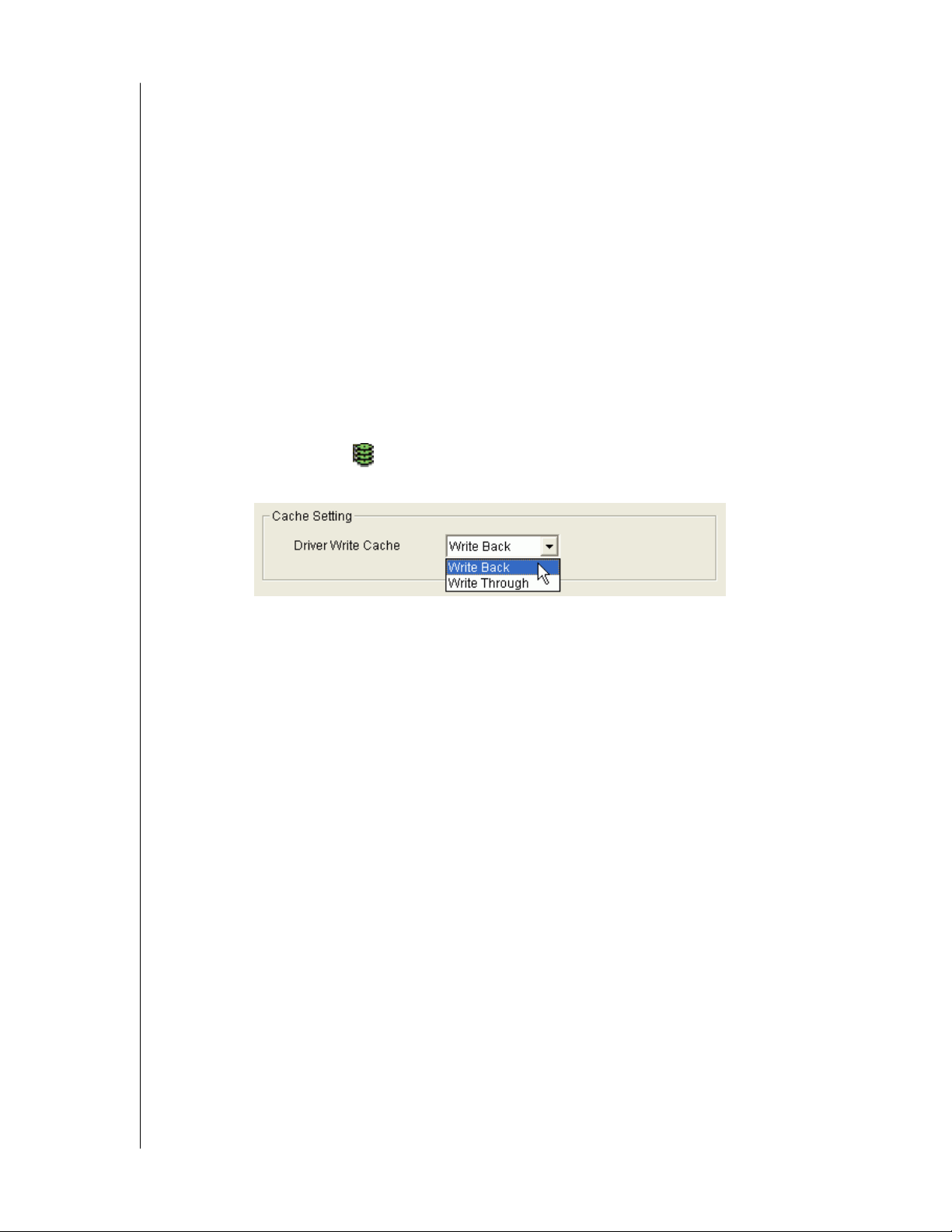
Array Cache Settings
Click on the Array View icon and look in the Information View to see the Array Cache
Setting.
Enable Driver Write Cache must be checked in Disk Parameters (see above) for this option to
work.
Click on the dropdown menu to select the Cache Setting.
Write Through - Data is written to the cache and hard drive at the same time. This
arrangement is safer.
Write Back - Data is written to the cache first and to the hard drive later. This arrangement
increases performance at the risk of data loss if the power fails.
CHAPTER 5: RAID MONITORING AND MAINTENANCE WITH AMS - 44
Page 49
WD ARRAY MANAGEMENT SETUP
USER MANUAL
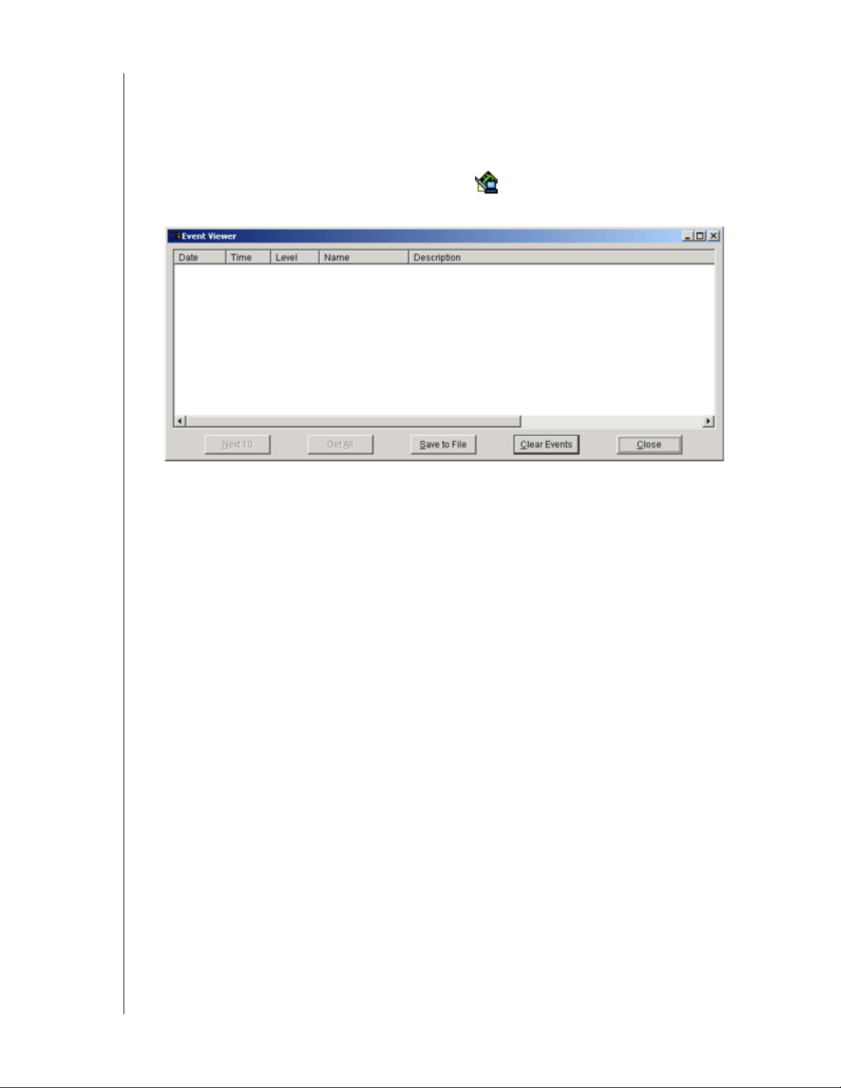
View Event Log
The Controller's Memory Buffer records all the events that happen on the RAID, classified as
Errors, Warnings, and Information.
These are very useful for diagnosing and solving problems on your system.
To see the Event Log, right-click on the Controller icon in Tree View and select Read
Events from the popup menu.
In the Event Viewer, you can view the events, make a permanent record by saving them to a
file, and clear the events from the Viewer.
You can also clear the events using the popup menu in Tree View.
Note that the collecting and reporting of these Events is independent from the Alert
Notification preferences set for the RAID System.
CHAPTER 5: RAID MONITORING AND MAINTENANCE WITH AMS - 45
Page 50

WD ARRAY MANAGEMENT SETUP
USER MANUAL
Arrays
Create an Array
The available RAID selection depends on the number of disk drives available.
The table below lists the RAID Levels available with WD SATA Controller and the number
of drives required.
See Appendix A: RAID Concepts for a more detailed description.
RAID Level Name Minimum drives Maximum drives
0 Striping 1 4
1 Mirroring 2 2
Table 4. RAID Levels available on the WD SATA RAID Controller.
1. In Tree View, click the + to the left of the Controller icon to see the Disk View icon.
Look under the Disk View icon to see the unassigned disk drives. Unassigned drives
have this icon.
2. Right-click on the Array View icon and select New Array from the popup menu. A
Create Array icon appears.
3. Select the Create Array icon and go to the Create Array Settings in Information
View.
Figure 20. Array Creation Setting Box
4. In the Array Creation Settings box:
- Type in a name for your array
- Select the RAID Mode (Level) from the dropdown menu
- Set the Stripe Block Size (see below)
- Highlight the disk drives to add to the array
- Check to enable Gigabyte Boundary, as desired (see below)
Stripe Block Size (RAID 0) - This setting allows you to manually select the stripe block
size. The size selected affects how the WD SATA RAID Controller sends and receives data
blocks to and from the drives. In general, a larger block size is better when handling large
CHAPTER 5: RAID MONITORING AND MAINTENANCE WITH AMS - 46
Page 51
WD ARRAY MANAGEMENT SETUP
USER MANUAL
data transfers (such as A/V editing and graphics) while a smaller size is better when
handling email and other common server data. The default is 64 KB. When in doubt, use
the default value.
Gigabyte Boundary (RAID 1) - This setting rounds the size of the array down to the
nearest whole gigabyte. It allows you to install a slightly smaller (within 1 GB)
replacement drive, should the need arise. To enable Gigabyte Boundary, check the box.
5. Click the Create button when you are done.
The new array appears in Tree View.
6. Restart your computer.
The next step is to partition and format the new array using the RAID PC's Operating
System. See Appendix B: Partition and Format for more information.
Hot Spare Drive
Using a Hot Spare Drive is an option for RAID 1 (Mirroring) arrays.
To function, a Hot Spare Drive has two requirements:
! Attach a third disk drive to the WD SATA Controller without assigning it to an array
! Do not Disable Hot Spare/Auto Rebuild in the Controller Options
Install a Third Drive
If necessary, see the WD SATA Controller User Manual for instructions how to install disk
drives with the WD SATA Controller.
CHAPTER 5: RAID MONITORING AND MAINTENANCE WITH AMS - 47
Page 52
WD ARRAY MANAGEMENT SETUP
Controller Settings
USER MANUAL
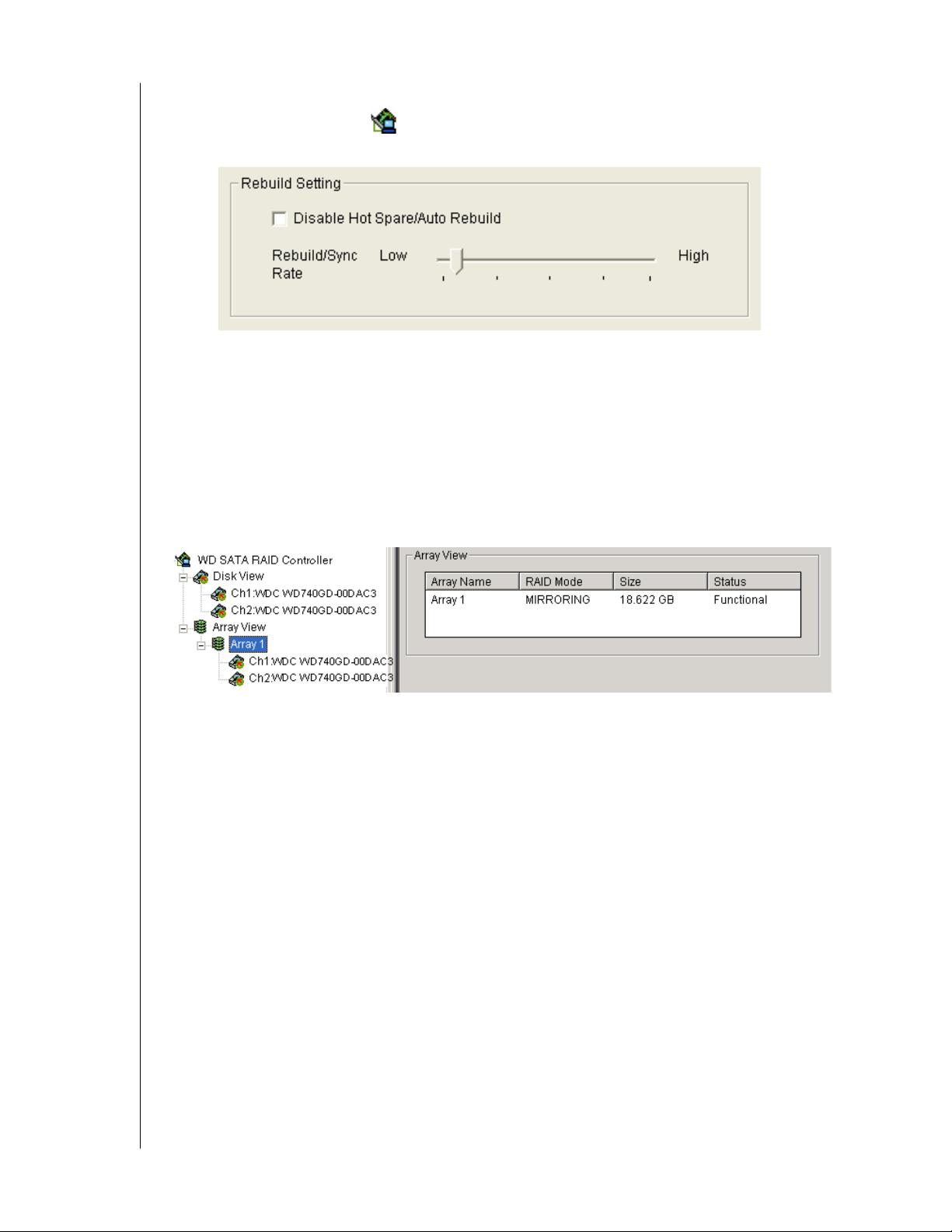
1. Click on the Controller icon in Tree View to see the Rebuild Setting in Information
View.
2. Be sure the checkbox is NOT checked:
Disable Hot Spare/Auto Rebuild - Disables automatic an automatic rebuild using a spare
drive not assigned to the array.
The Rebuild/Sync Rate is irrelevant to the Hot Spare Drive feature.
3. Click Submit.
Array Functional
When your array is first created, it will display Functional status.
If you have enabled Scheduled Synchronization, you will occasionally notice that your array is
Synchronizing. Then it returns again to Functional.
If your array encounters a problem with a disk drive, it will display Critical status. This
indicates that your array requires your attention to return to Functional.
When a disk drive fails on a non-fault-tolerant (RAID 0) array, the result is an Offline status.
CHAPTER 5: RAID MONITORING AND MAINTENANCE WITH AMS - 48
Page 53
WD ARRAY MANAGEMENT SETUP
USER MANUAL
Array Critical
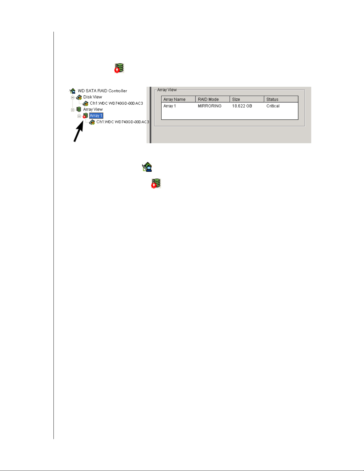
When a disk drive fails on a fault-tolerant array (RAID 1) for any reason, the Array goes
Critical. The array can still read and write data but fault tolerance has been lost.
An Array Critical icon displays in Tree View and the alarm (if enabled) beeps quickly to
call your attention to the condition.
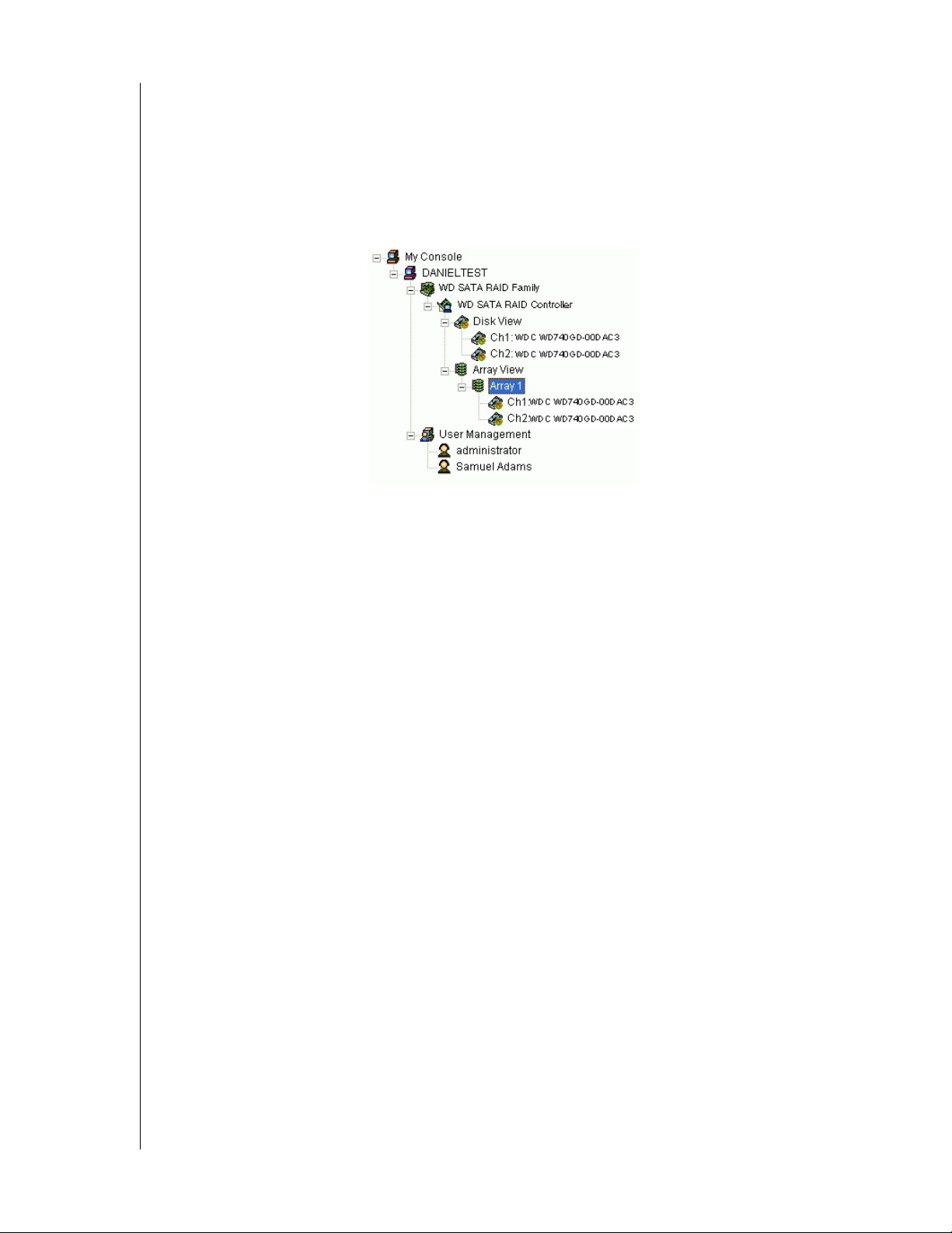
Your first action is to identify which disk drive has failed.
1. Click on the Controller icon to expand it.
2. Click on the Array Critical icon to expand it.
3. Observe and compare the disk drives currently displayed with those originally assigned to
the Array.
In the example above, there are two disk drives attached to the WD SATA RAID Controller
and both are assigned to a RAID 1 array.
The disk drive on Channel 2 does not appear. This is the failed drive.
! If you have a Hot Spare drive installed and enabled, the array will begin to Rebuild
automatically.
! If you do not have a Hot Spare drive, you must replace the failed drive before a Rebuild of
the array can begin.
Refer to the WD SATA Controller User Manual for more information about replacing a failed
drive.
After you replace the failed drive, go on to “Rebuild an Array” on page 51.
CHAPTER 5: RAID MONITORING AND MAINTENANCE WITH AMS - 49
Page 54
WD ARRAY MANAGEMENT SETUP
USER MANUAL
Array Offline
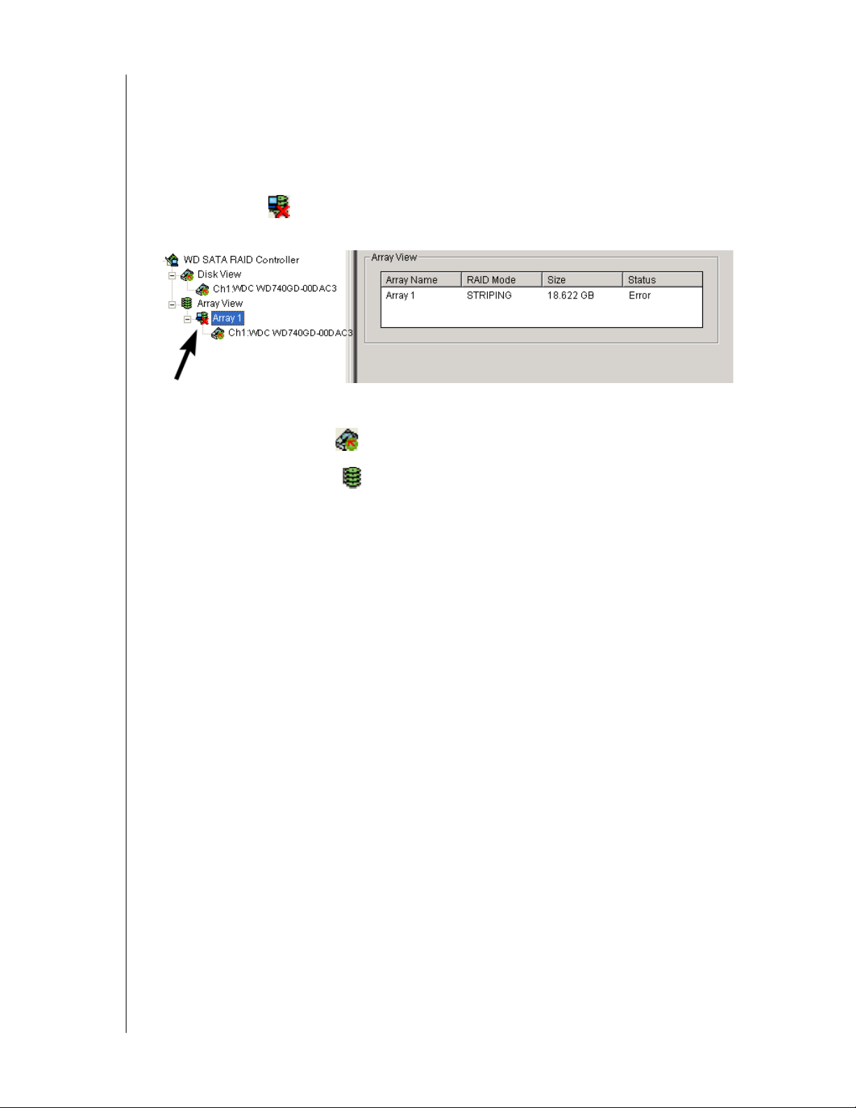
When a disk drive fails on a non-fault-tolerant array (RAID 0) for any reason, the Array goes
Offline. The array cannot read or write data. All of the data on the array will be lost unless the
failed drive is restored to operation.
A fault-tolerant array (RAID 1) will go Offline if two disk drives fail.
An Array Offline icon displays in Tree View and the alarm (if enabled) beeps quickly to
call your attention to the condition.
Your first action is to identify which disk drive has failed.
1. Click on the Disk View icon to expand it.
2. Click on the Array View icon to expand it.
3. Look for the drive that was part of this Array but is now missing. Observe and compare
the disk drives under the Controller with those under the Array.
In the example above, two disk drives attached to the WD SATA RAID Controller were
assigned to a RAID 0 array.
The disk drive on Channel 1 is present, but the second drive is not. The second is the
failed drive.
4. When you have identified the failed drive, check its connections and run the drive
manufacturer's diagnostic program in an effort to restore the drive to operation.
There is no Rebuild function for a non-fault-tolerant array.
CHAPTER 5: RAID MONITORING AND MAINTENANCE WITH AMS - 50
Page 55
WD ARRAY MANAGEMENT SETUP
USER MANUAL
Rebuild an Array
To rebuild is to restore redundancy to a RAID 1 after one of its drives has failed. Unlike
Synchronization, a rebuild is a repair operation.
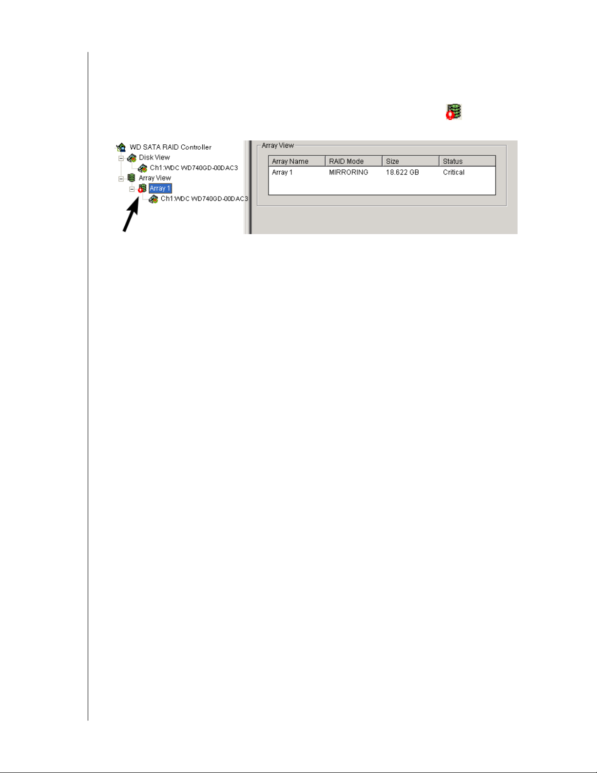
When a drive fails for any reason, the Array goes Critical. An Array Critical icon displays
in Tree View and the RAID alarm beeps quickly to call your attention to the condition.
Automatic rebuild
Normally, the rebuild process begins automatically when you replace the faulty disk drive.
The array recognizes the new or spare drive and begins the process a few moments later.
If your array has a Hot Spare drive, the rebuild begins without waiting for a replacement
drive.
Be sure to replace the faulty drive as soon as possible.
During the rebuild process, the array is still available to read and write data but it may run
noticeably slower.
To enable a Hot Spare drive, change the rebuild settings and shut off the beeper, see rebuild
Settings, below.
If the popup messages are enabled, one will notify you when the rebuild is successfully
completed. The array will return to Functional status.
CHAPTER 5: RAID MONITORING AND MAINTENANCE WITH AMS - 51
Page 56
WD ARRAY MANAGEMENT SETUP
Manual Rebuild
USER MANUAL
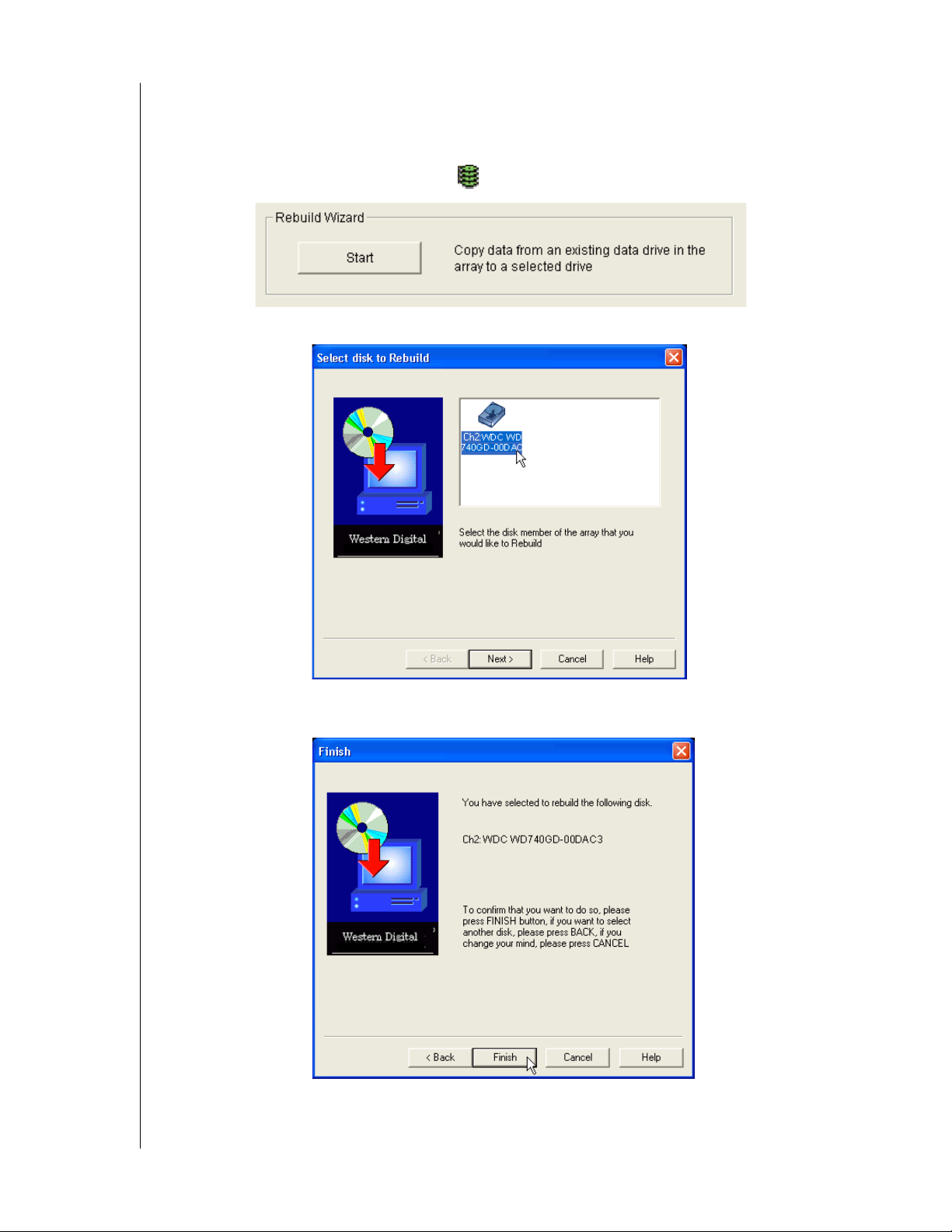
After you replace a failed disk drive, the replacement drive must be rebuilt to restore the array.
To initiate an array Rebuild manually:
1. In Tree View, select the Array View iconof the array you want to rebuild.
2. In Information View, click on the Start button inside the Rebuild Wizard box.
3. In the Rebuild Wizard, select the drive to be rebuilt (the replacement drive) and click
Next.
To confirm the rebuild choice, click Finish.
CHAPTER 5: RAID MONITORING AND MAINTENANCE WITH AMS - 52
Page 57
WD ARRAY MANAGEMENT SETUP
USER MANUAL
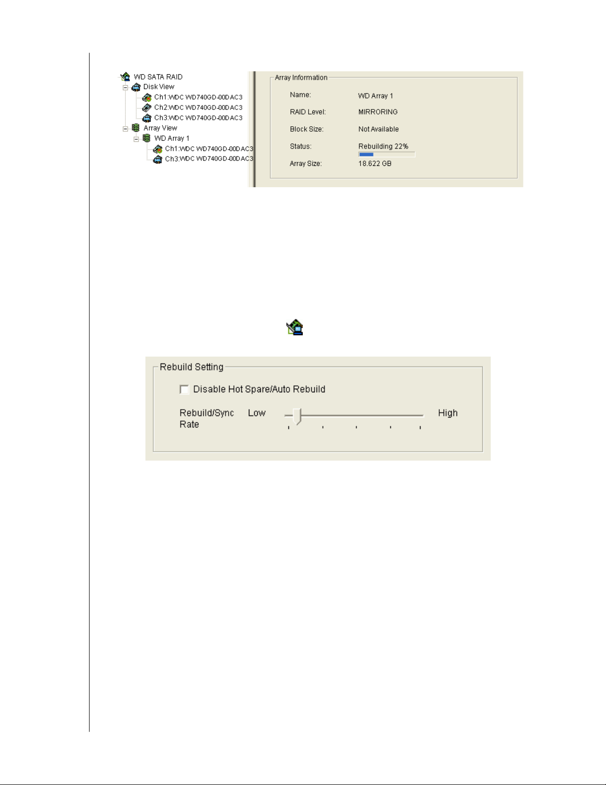
Tree View and Information View display the progress (below).
During the Rebuild process, the array will be available for use but it may run noticeably
slower.
If the beeper is enabled, it will beep slowly during this process.
If the popup messages are enabled, one will notify you when the Rebuild is successfully
completed. The array will return to Functional status.
Rebuild Settings
Beeper - Right-click on the Controller icon and select Beeper from the popup menu. A
checkmark means the beeper is enabled.
Disable Hot Spare/Auto Rebuild - Disables automatic rebuilding using a hot spare drive or a
newly installed replacement drive. With this option checked, you must initiate rebuilding
manually. See RAID 1 (Mirroring) and Hot Spare Drive.
Rebuild/Sync Rate - Allocates system resources between rebuilding the array and responding
to read/write commands from the computer system.
A High setting assigns most of the system resources to a rebuild or synchronization of the
array. The process will finished sooner but read/write requests are handled slower.
A Low setting assigns most of the system resources to handling read/write requests. Read/
write requests are handled at nearly normal speed while the rebuild or synchronization takes
longer.
CHAPTER 5: RAID MONITORING AND MAINTENANCE WITH AMS - 53
Page 58
WD ARRAY MANAGEMENT SETUP
USER MANUAL
Synchronize an Array
WD uses the term synchronization to mean an automated process of checking and correcting
data and parity. Unlike a Rebuild, Synchronization is a maintenance operation.
Synchronization applies to RAID 1. It takes place when an array is first created and then,
optionally, on a regularly scheduled basis to maintain content integrity.
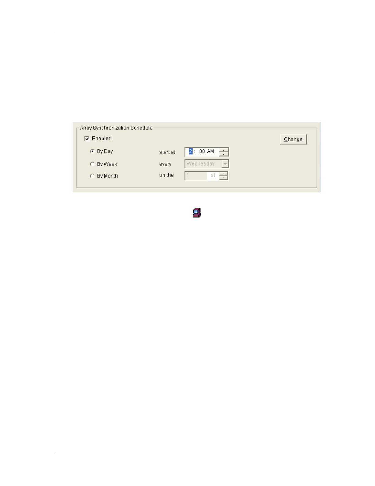
Scheduled Synchronization
Schedule a time for synchronization when the RAID is least busy reading and writing data.
The early morning hours are often a convenient time.
To enable scheduled synchronization:
1. In Tree View, select the RAID Machine icon. In Information View, scroll down to
the bottom.
2. Check the Enabled box.
3. Click on the radio button beside the time interval (by day, week or month) you want.
4. Based on the time interval you selected, enter the clock time, day of the week or day of the
month for the synchronization process to begin.
5. When you are done, click the Change button.
The Synchronization Schedule is set. If the Schedule is disabled, it will remember its current
settings.
CHAPTER 5: RAID MONITORING AND MAINTENANCE WITH AMS - 54
Page 59
WD ARRAY MANAGEMENT SETUP
USER MANUAL
On Demand Synchronization
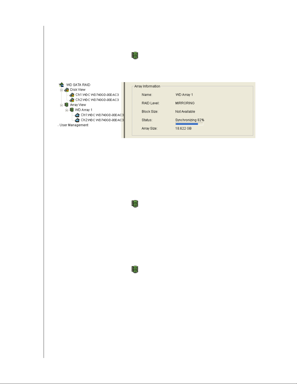
In addition to schedule Synchronization, you can direct the WD SATA RAID Controller to
begin the Synchronization process immediately. To access this feature:
1. Right-click on the Array View icon and select Synchronize from the popup menu.
2. Click OK to the confirmation message.
Information View displays the progress (below).
During the Synchronization, the array will be available for use but it may run noticeably
slower.
If the popup messages are enabled, one will notify you when the Synchronization is
successfully completed. The array will return to Functional status.
Stop, Pause, Continue
WD recommends that you let your rebuild run to completion. If you need to pause the
process:
1. Right-click on the Array View icon of the Array that is rebuilding and select Pause
from the popup menu.
2. To continue, right-click on the same icon again and select Continue from the popup
menu.
Delete an Array
To delete an array:
1. Right-click on the Array View icon of the Array you want to delete.
2. Select Delete from the popup menu.
3. Click OK in the confirmation dialog box.
CHAPTER 5: RAID MONITORING AND MAINTENANCE WITH AMS - 55
Page 60
WD ARRAY MANAGEMENT SETUP
USER MANUAL
Appendix A: RAID Concepts
RAID
RAID is an acronym that stands for Redundant Array of Independent Disks. It is divided into
different numbered Levels. The numbers of these Levels do not mean that one Level is higher
or better than another. Each Level has its own advantages and shortcomings.
AMS allows you to select the RAID Level when you create an Array. The available RAID
Level selection depends on which WD product you have and the number of disk drives
available.
The table below lists the RAID Levels obtainable with the WD SATA RAID Controller.
RAID Level Name Minimum drives Maximum drives
0 Striping 1 4
1 Mirroring 2 2
Table 4. RAID Levels available on the WD SATA RAID Controller
Following is a discussion how these RAID Levels work.
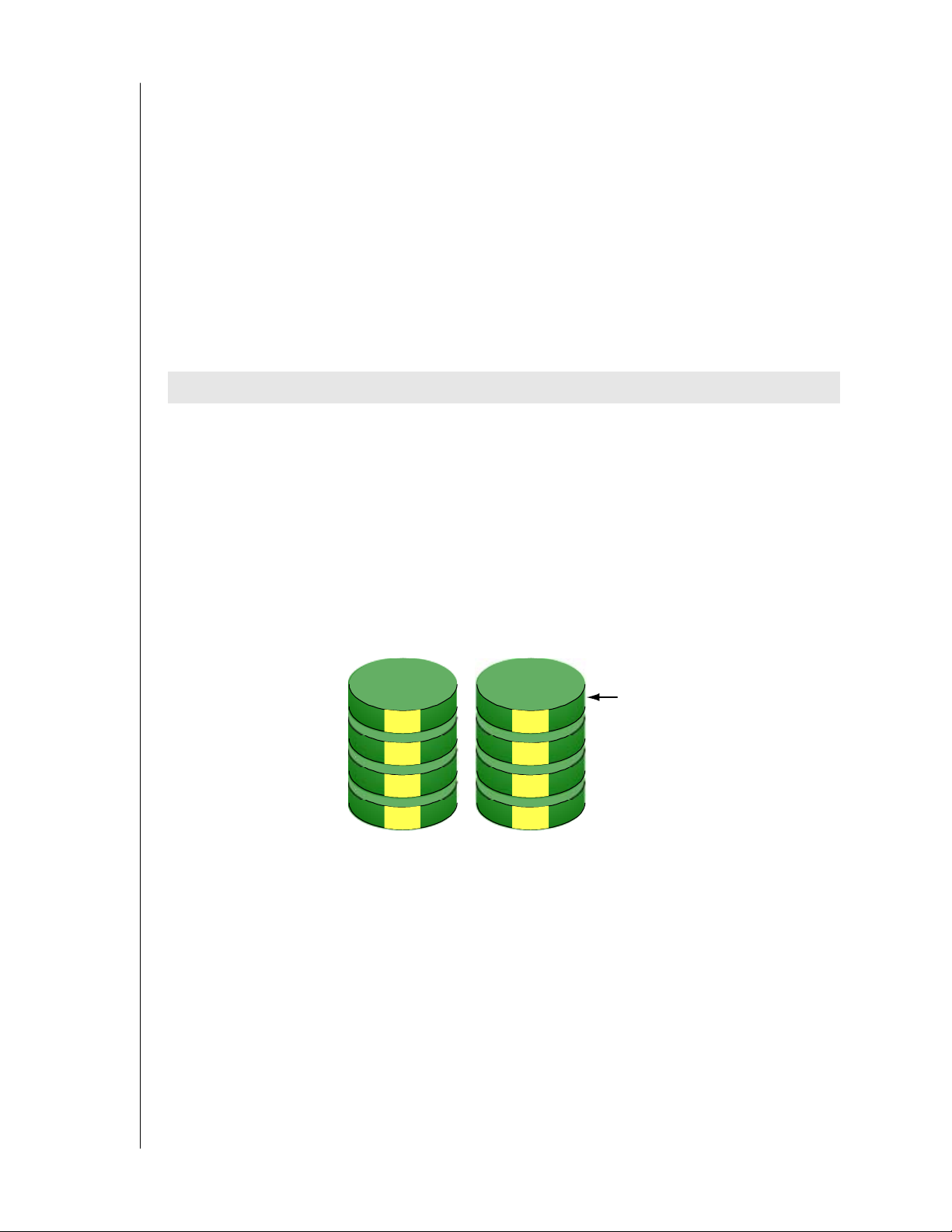
RAID 0
RAID 0 is a method of striping or writing data over two or more hard disks at the same time.
Multiple disks can read and write data faster than one. However, there is no data redundancy
with this arrangement, so if one disk fails, all your data is lost..
Data
Stripe
1
3
5
7
Disk Drives
2
4
6
8
APPENDIX A: RAID CONCEPTS - 56
Page 61
WD ARRAY MANAGEMENT SETUP
USER MANUAL
RAID 1
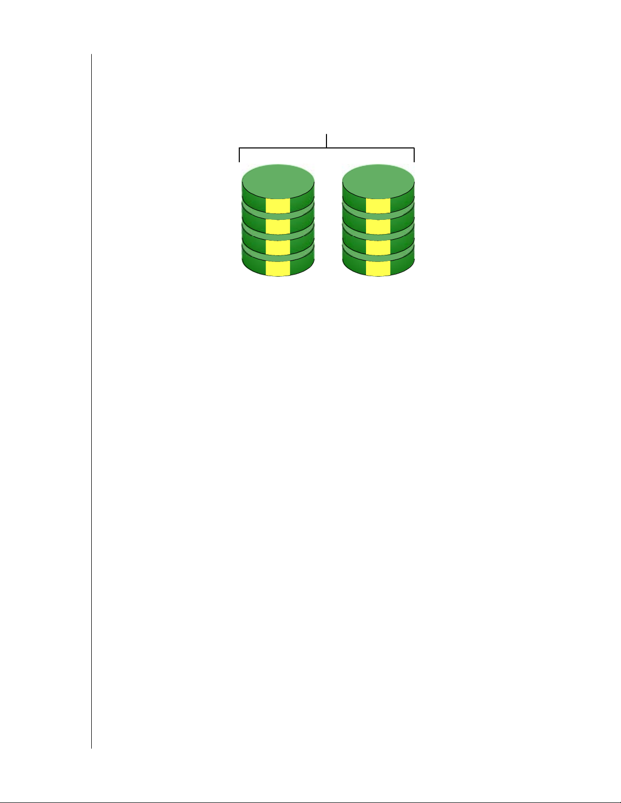
RAID 1 takes the data written on one disk and copies it to another, making a mirror or exact
copy. This arrangement does not have a significant performance advantage. If one disk fails,
there is no data loss. There is no rebuild, just a copy of the data to the disk.
Data Mirror
1
2
3
4
1
2
3
4
Disk Drives
APPENDIX A: RAID CONCEPTS - 57
Page 62
WD ARRAY MANAGEMENT SETUP
USER MANUAL
Appendix B: Partition and Format
For Windows to recognize and work with your array, you must partition and format the array.
These actions create a file structure within your array with which Windows can work.
Note: If you plan to boot your computer from this array, go to Windows and Device Driver
Installation under the Installation section for instructions. The instructions here are for data
arrays only.
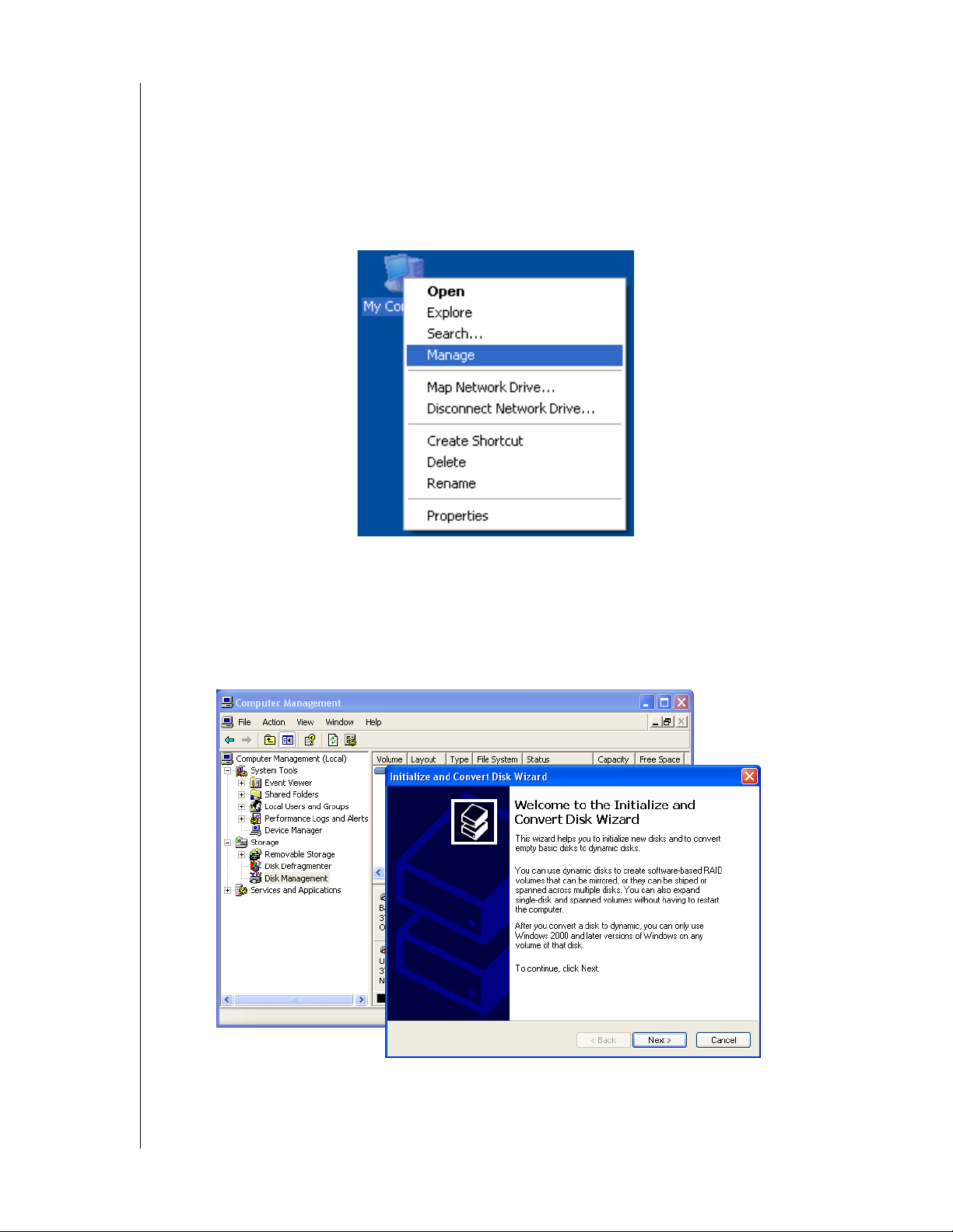
Figure 40. Right-click on the My Computer icon
1. From the desktop, right-click on the My Computer icon and select Manage from the
popup menu. The Computer Management window opens.
2. From the left menu, click on Disk Management. The Disk Management window opens
with your new array identified as Disk 1. The Initialize Wizard appears automatically.
Figure 41. The Disk Management Window and Disk Wizard
3. Click the Next button to start the Wizard.
APPENDIX B: PARTITION AND FORMAT - 58
Page 63
WD ARRAY MANAGEMENT SETUP
USER MANUAL
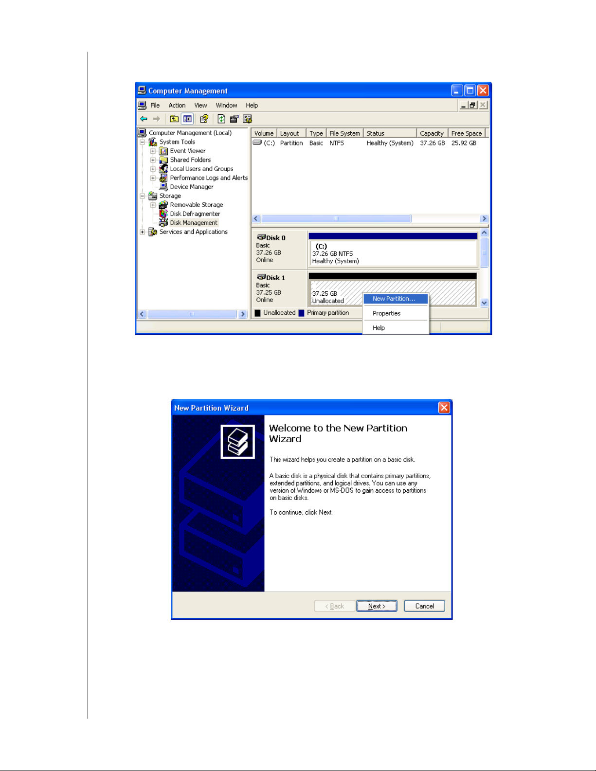
4. In the following windows, select Disk 1 to Initialize. Do not select any disks to Convert.
Click the Finish button to Initialize the array.
Figure 42. Initialized array ready for partition and format
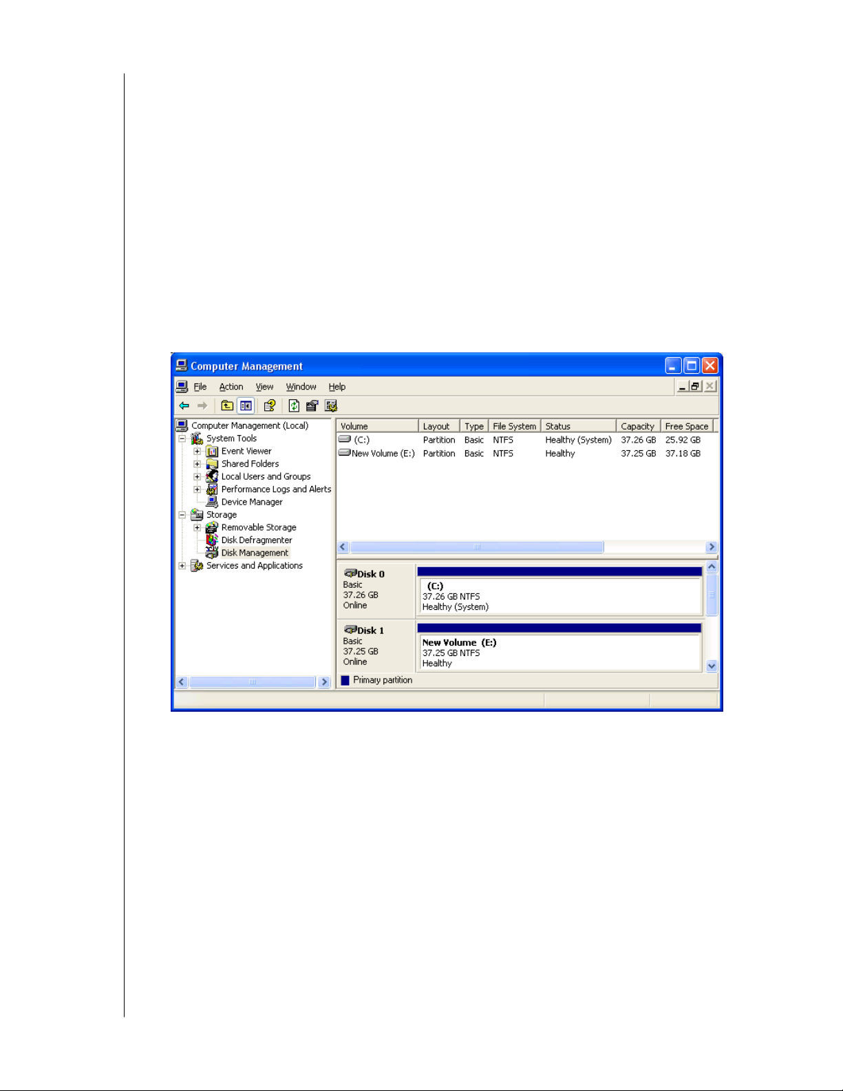
5. Right-click on the Unallocated portion of Disk 1 and select New Partition... from the
popup menu. The New Partition Wizard appears.
Figure 43. The New Partition Wizard
6. Click the Next button to start the wizard.
APPENDIX B: PARTITION AND FORMAT - 59
Page 64
WD ARRAY MANAGEMENT SETUP
USER MANUAL
7. In the following windows, do the following actions. Click Next to move to the next
window.
- Select Primary Partition
- Specify the maximum available partition size in MB
- Assign the available drive letter of your choice
- Choose Format this partition with the following settings
- File system: NTFS
- Allocation unit size: Default
- Volume label: Enter your choice of name
- Do not check "Perform a quick format" or "Enable file and folder compression"
8. Review your selections and click Finish. The New Partition Wizard will disappear while
partitioning and formatting begin.
This process will take some time. The Disk Management window displays the progress.
Figure 44. The newly formatted array as it appears under Disk Management
APPENDIX B: PARTITION AND FORMAT - 60
Page 65
WD ARRAY MANAGEMENT SETUP
USER MANUAL
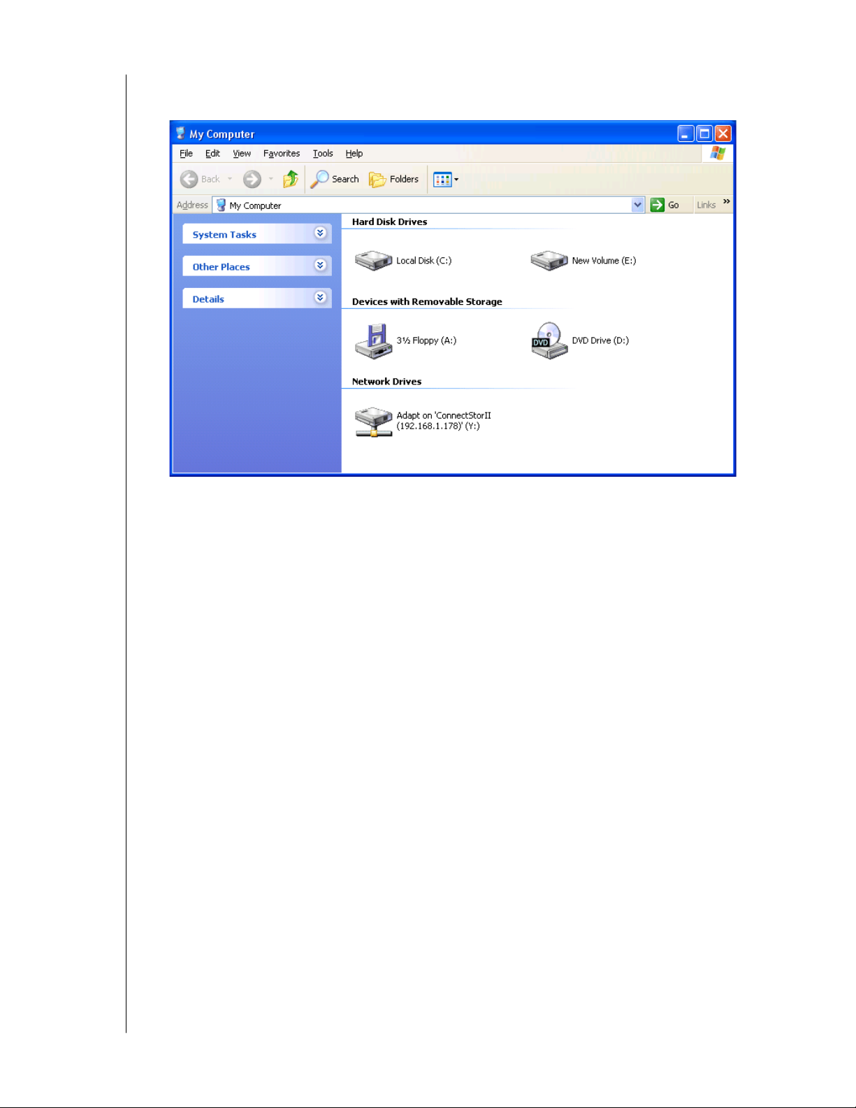
When formatting is complete, your array will appear as a hard drive in the Disk Management
window (above) and the My Computer window (below).
Figure 45. The newly formatted array under My Computer
APPENDIX B: PARTITION AND FORMAT - 61
Page 66
WD ARRAY MANAGEMENT SETUP
USER MANUAL
Appendix C: Networking Issues
IP Address
To configure AMS over a network, you must know the IP (network) address of every
component. The Message Server uses IP addresses to communicate with the Message Agent
on the RAID PCs and the Monitoring Utility on the network PCs.
To find the IP network address:
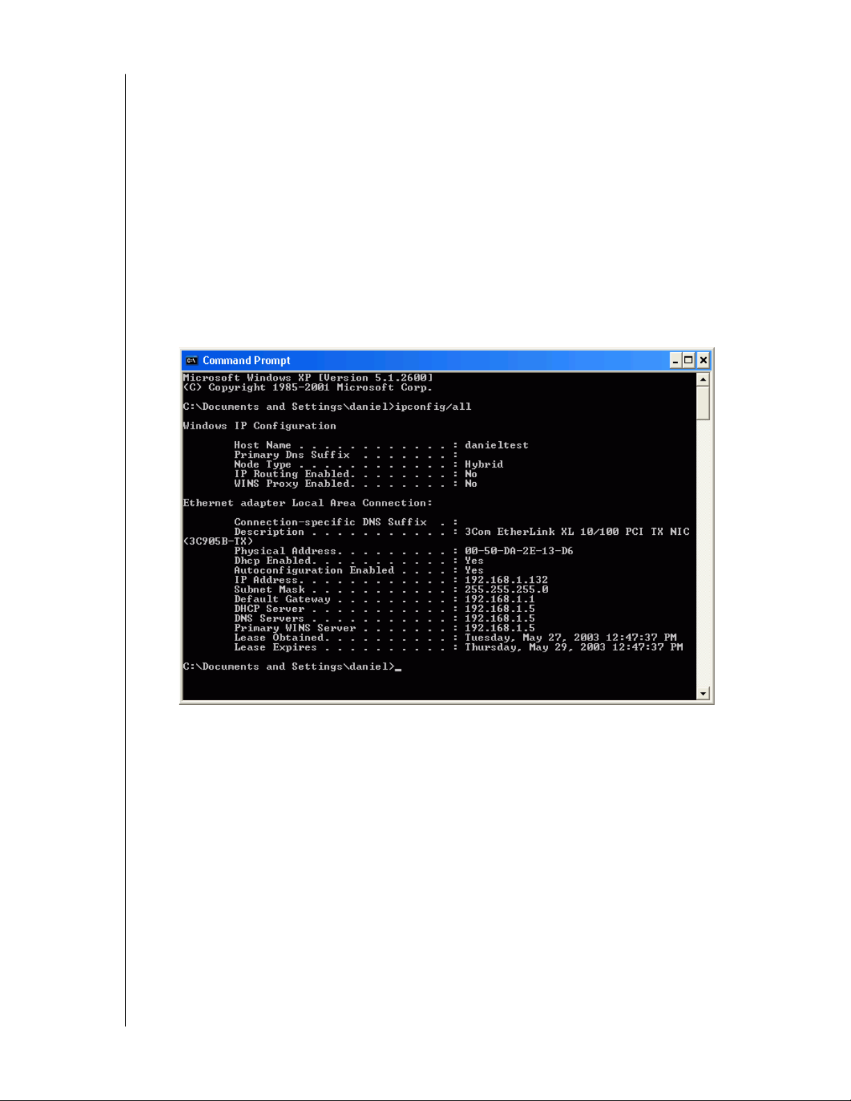
1. Go to Start > Programs > Accessories > Command Prompt.
2. Type ipconfig/all and press Enter.
The Windows IP Configuration displays (below).
Figure 46. Use the Command Prompt to find your PC's IP address
In the example above, the IP address of this PC is 192.168.1.132.
Locate and record the IP addresses of all PCs and Servers on your network that will work with
AMS. This document will help you recall individual PCs when it is time to specify their
connections.
APPENDIX C: NETWORKING ISSUES - 62
Page 67

WD ARRAY MANAGEMENT SETUP
USER MANUAL
DHCP Issues
Referring to the Figure 84 above, note that it says:
Dhcp enabled. . . . . . . . : Yes
This means that a DHCP server gave this IP address to this PC when the PC connected to the
network. DHCP stands for Dynamic Host Configuration Protocol and refers to software that
allows a file server to assign IP addresses to computers on the network.
DHCP is very helpful in reducing the number of IP address a company or organization
requires. The DHCP server assigns an IP address to a computer as it logs onto the network.
The IP address will remain the same until the computer logs off or disconnects for any reason,
such as a power failure. When the computer logs on again, it will receive a different IP
address.
Because IP addresses are subject to change when a DHCP server is involved, make it a point
to maintain the RAID PC network connections at all times. When a disconnection happens
for any reason, you must find the new IP address and enter it into the Message Server.
Instructions for doing this appear under Message Server IP Address Change in Chapter 5.
To avoid having to make Message Server IP Address changes, assign the RAID PC a
permanent IP address. See your IT Manager for guidance.
APPENDIX C: NETWORKING ISSUES - 63
Page 68

WD ARRAY MANAGEMENT SETUP
USER MANUAL
Appendix D: WD Service and Support
If you need additional information or help during the installation or normal use of this
product, visit our product support Web site at support.wdc.com to choose from the following
options:
! Warranty Services–Obtain warranty information, warranty status, product replacement,
RMA status, and shipping and packaging information.
! Downloads Library–Download installation software and drivers.
! Technical Information–Get access to product specifications, technical tips, and online
forum.
! Knowledge Base–Explore our expert knowledge base and frequently asked questions
(FAQs).
! Service & Support Options–Look up available service and support options in your
region.
! Contact Support–Contact a support representative by phone or e-mail.
APPENDIX D: WD SERVICE AND SUPPORT - 64
 Loading...