


3/Vista Series Blending and Non-blending Suction Pumps and Remote Dispensers

DANGER
READ THIS MANUAL BEFORE YOU BEGIN
Dispensers have both electricity and a hazardous, flammable and potentially explosive liquid. Failure to follow the below precautions and the Warning and Caution instructions in this manual may result in serious injury. Follow all rules, codes and laws that apply to your area and installation.
SAFETY PRECAUTIONS - INSTALLATION AND MAINTENANCE
Always make sure ALL power to the dispenser is turned OFF before you open the dispenser cabinet for maintenance. Physically lock, restrict access to, or tag the circuit breakers you turn off when servicing the dispenser. Be sure to trip (close) the emergency valve(s) under the dispenser BEFORE beginning maintenance.
Make sure that you know how to turn OFF power to the dispenser and submersible pumps in an emergency. Have all leaks or defects repaired immediately.
EQUIPMENT PRECAUTIONS
Be sure to bleed all air from product lines of remote dispensers and prime suction pumps before dispensing product, otherwise, damage to the equipment may occur. Always use the approved method for lifting the dispenser. Never lift by the nozzle boot, sheet metal, valance, etc., otherwise equipment damage or personal injury may occur.
HOW TO CONTACT WAYNE
Trouble with the installation and operation of the dispenser should be referred to your authorized Wayne service personnel or Wayne Technical Support (1-800-926-3737).
INDICATORS AND NOTATIONS
DANGER
WARNING
CAUTION
NOTE:
Danger indicates a hazard or unsafe practice which, if not avoided, will result in severe injury or possibly death.
Warning indicates a hazard or unsafe practice which, if not avoided, may result in severe injury or possibly death.
Caution indicates a hazard or unsafe practice which, if not avoided, may result in minor injury.
Important information to consider, otherwise, improper installation and/or damage to components may occur.

3/Vista Series Blending and Non-Blending
Suction Pumps and
Remote Dispensers
Installation & Operation
March 2003 |
Part No. 920365 Rev B |

Part No. 920365 Rev B |
March 2003 |

Table of Contents
Title |
|
|
Page |
1 |
INTRODUCTION . . . . . . . . . . . . . . . . . . . . . . . . . . . . . . . . . . . . . . . . . . . . . . . . . . . . . . . . . . . |
. . . 1 |
|
|
1.1 |
Dispensers Covered . . . . . . . . . . . . . . . . . . . . . . . . . . . . . . . . . . . . . . . . . . . . . . . . . . |
. . . 1 |
|
1.2 |
Local, State, and Federal Codes . . . . . . . . . . . . . . . . . . . . . . . . . . . . . . . . . . . . . . . . . |
. . . 2 |
|
1.3 |
Safety Precautions . . . . . . . . . . . . . . . . . . . . . . . . . . . . . . . . . . . . . . . . . . . . . . . . . . . |
. . . 4 |
2 |
INSTALLATION . . . . . . . . . . . . . . . . . . . . . . . . . . . . . . . . . . . . . . . . . . . . . . . . . . . . . . . . . . . |
. . . 5 |
|
2.1 Inspect the Equipment . . . . . . . . . . . . . . . . . . . . . . . . . . . . . . . . . . . . . . . . . . . . . . . . . . . . 5 2.2 Island Construction, Dispenser Anchoring, and Piping . . . . . . . . . . . . . . . . . . . . . . . . . . . 5 2.3 Vapor Return Piping . . . . . . . . . . . . . . . . . . . . . . . . . . . . . . . . . . . . . . . . . . . . . . . . . . . . . 5 2.4 Check Valves (Suction Pumps) . . . . . . . . . . . . . . . . . . . . . . . . . . . . . . . . . . . . . . . . . . . . . 7 2.5 Connecting More Than One Pump to a Tank (Suction Pumps) . . . . . . . . . . . . . . . . . . . . 7 2.6 Lifting and Installing the Dispenser . . . . . . . . . . . . . . . . . . . . . . . . . . . . . . . . . . . . . . . . . . 8 2.7 Electrical Wiring . . . . . . . . . . . . . . . . . . . . . . . . . . . . . . . . . . . . . . . . . . . . . . . . . . . . . . . . . 9
2.7.1 General . . . . . . . . . . . . . . . . . . . . . . . . . . . . . . . . . . . . . . . . . . . . . . . . . . . . . . . . . . 9 2.7.2 Full Service (Stand-Alone) Dispenser Wiring . . . . . . . . . . . . . . . . . . . . . . . . . . . . . 9 2.7.3 Submersible Pump Control Relays. . . . . . . . . . . . . . . . . . . . . . . . . . . . . . . . . . . . . 9 2.7.4 Multiple Dispenser Wiring . . . . . . . . . . . . . . . . . . . . . . . . . . . . . . . . . . . . . . . . . . . . 9 2.7.5 Dispenser to Wayne Control System Wiring . . . . . . . . . . . . . . . . . . . . . . . . . . . . 11 2.7.6 Optional Equipment . . . . . . . . . . . . . . . . . . . . . . . . . . . . . . . . . . . . . . . . . . . . . . . 11 2.7.7 Non-Dispenser Equipment . . . . . . . . . . . . . . . . . . . . . . . . . . . . . . . . . . . . . . . . . . 11
2.8 Sale Display Lights . . . . . . . . . . . . . . . . . . . . . . . . . . . . . . . . . . . . . . . . . . . . . . . . . . . . . 12 2.9 Hose Installation . . . . . . . . . . . . . . . . . . . . . . . . . . . . . . . . . . . . . . . . . . . . . . . . . . . . . . . 12 2.10 Bleeding Product Lines (Remote Dispensers). . . . . . . . . . . . . . . . . . . . . . . . . . . . . . . . . 12 2.11 Priming Suction Pumps . . . . . . . . . . . . . . . . . . . . . . . . . . . . . . . . . . . . . . . . . . . . . . . . . . 13 2.12 Above Ground Storage Tanks . . . . . . . . . . . . . . . . . . . . . . . . . . . . . . . . . . . . . . . . . . . . . 13 2.13 Meter Calibration . . . . . . . . . . . . . . . . . . . . . . . . . . . . . . . . . . . . . . . . . . . . . . . . . . . . . . . 14 2.14 Balance Vapor Recovery System Installation Requirements . . . . . . . . . . . . . . . . . . . . . 16
2.14.1 Dynamic Back Pressure Test . . . . . . . . . . . . . . . . . . . . . . . . . . . . . . . . . . . . . . . . 16 2.14.2 Back Pressure System Check List . . . . . . . . . . . . . . . . . . . . . . . . . . . . . . . . . . . . 16 2.15 Wayne Vac Vapor Recovery System Installation Requirements . . . . . . . . . . . . . . . . . . 17 2.15.1 Dispenser Vacuum Decay . . . . . . . . . . . . . . . . . . . . . . . . . . . . . . . . . . . . . . . . . . 17 2.15.2 Wayne Pressure/Vacuum Tester . . . . . . . . . . . . . . . . . . . . . . . . . . . . . . . . . . . . . 17
3 START-UP . . . . . . . . . . . . . . . . . . . . . . . . . . . . . . . . . . . . . . . . . . . . . . . . . . . . . . . . . . . . . . . . . . 19
3.1 Initial Checkout . . . . . . . . . . . . . . . . . . . . . . . . . . . . . . . . . . . . . . . . . . . . . . . . . . . . . . . . 19 3.2 Hose Position Coding for Blenders . . . . . . . . . . . . . . . . . . . . . . . . . . . . . . . . . . . . . . . . . 19 3.2 Hose Position Coding for non-Blenders . . . . . . . . . . . . . . . . . . . . . . . . . . . . . . . . . . . . . 20 3.4 Infrared Remote Control . . . . . . . . . . . . . . . . . . . . . . . . . . . . . . . . . . . . . . . . . . . . . . . . . 20 3.4 Setting Unit Prices . . . . . . . . . . . . . . . . . . . . . . . . . . . . . . . . . . . . . . . . . . . . . . . . . . . . . . 22 3.5 Setting Blend Ratios . . . . . . . . . . . . . . . . . . . . . . . . . . . . . . . . . . . . . . . . . . . . . . . . . . . . 24 3.6 Setting Fueling Point ID . . . . . . . . . . . . . . . . . . . . . . . . . . . . . . . . . . . . . . . . . . . . . . . . . . 26 3.7 Authorizing the Dispenser . . . . . . . . . . . . . . . . . . . . . . . . . . . . . . . . . . . . . . . . . . . . . . . . 27
iii
June 2003 |
Part No. 920365 Rev B |

|
Table of Contents (continued) |
|
Title |
|
Page |
3.8 |
Initial Delivery . . . . . . . . . . . . . . . . . . . . . . . . . . . . . . . . . . . . . . . . . . . . . . . . . . . . . . . |
. . 27 |
3.9 |
Totalizer Readings. . . . . . . . . . . . . . . . . . . . . . . . . . . . . . . . . . . . . . . . . . . . . . . . . . . . |
. . 28 |
|
3.9.1 Totalizer Readings by Product Position . . . . . . . . . . . . . . . . . . . . . . . . . . . . . . |
. . 28 |
|
3.9.2 Totalizer Volume Readings by Meter Position . . . . . . . . . . . . . . . . . . . . . . . . . |
. . 30 |
|
3.9.3 Electro-Mechanical Totalizer Operation . . . . . . . . . . . . . . . . . . . . . . . . . . . . . . |
. . 33 |
3.10 |
Nozzle Boot Switch Check . . . . . . . . . . . . . . . . . . . . . . . . . . . . . . . . . . . . . . . . . . . . . |
. . 34 |
|
3.10.1 Lift-to-Start Version. . . . . . . . . . . . . . . . . . . . . . . . . . . . . . . . . . . . . . . . . . . . . . |
. . 34 |
|
3.10.2 Push-to-Start Version . . . . . . . . . . . . . . . . . . . . . . . . . . . . . . . . . . . . . . . . . . . . |
. . 34 |
3.11 |
V-link belt. . . . . . . . . . . . . . . . . . . . . . . . . . . . . . . . . . . . . . . . . . . . . . . . . . . . . . . . . . . |
. . 34 |
3.12 |
Annunciator Operation. . . . . . . . . . . . . . . . . . . . . . . . . . . . . . . . . . . . . . . . . . . . . . . . . |
. . 35 |
3.13 |
Wayne Vac Motor Operation . . . . . . . . . . . . . . . . . . . . . . . . . . . . . . . . . . . . . . . . . . . . |
. . 35 |
3.14Audit Report Display Mode (For Weights & Measures Officials/Service Purposes Only) 35
4 |
OPERATION . . . . . . . . . . . . . . . . . . . . . . . . . . . . . . . . . . . . . . . . . . . . . . . . . . . . . . . . . . . . . . . . |
37 |
|
|
4.1 |
Safety Items You Should Know . . . . . . . . . . . . . . . . . . . . . . . . . . . . . . . . . . . . . . . . . . . . |
37 |
|
|
4.1.1 Portable Tanks and Containers . . . . . . . . . . . . . . . . . . . . . . . . . . . . . . . . . . . . . . |
37 |
|
|
4.1.2 Health Note. . . . . . . . . . . . . . . . . . . . . . . . . . . . . . . . . . . . . . . . . . . . . . . . . . . . . . |
37 |
|
|
4.1.3 European Community Conformity Identification . . . . . . . . . . . . . . . . . . . . . . . . . . |
40 |
|
4.2 |
Introduction to Operation . . . . . . . . . . . . . . . . . . . . . . . . . . . . . . . . . . . . . . . . . . . . . . . . . |
40 |
|
4.3 |
Operation of non-Blenders . . . . . . . . . . . . . . . . . . . . . . . . . . . . . . . . . . . . . . . . . . . . . . . |
41 |
|
4.4 |
Operation of 3/V595 Models . . . . . . . . . . . . . . . . . . . . . . . . . . . . . . . . . . . . . . . . . . . . . . |
42 |
|
4.5 |
Operation of 3/V580, 3/V590/U, 3/V585, and 3/V595/U Models . . . . . . . . . . . . . . . . . . . |
42 |
|
4.6 |
Operation of 3/V590 and 3/V591 Models . . . . . . . . . . . . . . . . . . . . . . . . . . . . . . . . . . . . |
43 |
|
4.7 |
Restarting After Power Failure or Shutdown . . . . . . . . . . . . . . . . . . . . . . . . . . . . . . . . . . |
43 |
|
4.8 |
Cycling Power to Clear Faults . . . . . . . . . . . . . . . . . . . . . . . . . . . . . . . . . . . . . . . . . . . . . |
43 |
|
4.9 |
Error Codes . . . . . . . . . . . . . . . . . . . . . . . . . . . . . . . . . . . . . . . . . . . . . . . . . . . . . . . . . . . |
44 |
|
4.10 |
Resetting After All Stop . . . . . . . . . . . . . . . . . . . . . . . . . . . . . . . . . . . . . . . . . . . . . . . . . . |
45 |
|
4.11 |
Customer Activated Terminal . . . . . . . . . . . . . . . . . . . . . . . . . . . . . . . . . . . . . . . . . . . . . |
45 |
|
4.12 |
Stand-alone Operation For 3/Vista Series Dispensers . . . . . . . . . . . . . . . . . . . . . . . . . . |
45 |
|
4.13 |
How To Get Service On Your Dispenser. . . . . . . . . . . . . . . . . . . . . . . . . . . . . . . . . . . . . |
46 |
5 OPERATOR MAINTENANCE . . . . . . . . . . . . . . . . . . . . . . . . . . . . . . . . . . . . . . . . . . . . . . . . . . . |
47 |
||
5.1 |
Preventive Maintenance . . . . . . . . . . . . . . . . . . . . . . . . . . . . . . . . . . . . . . . . . . . . . . . . . |
47 |
|
5.2 |
Strainer/Filter . . . . . . . . . . . . . . . . . . . . . . . . . . . . . . . . . . . . . . . . . . . . . . . . . . . . . . . . . . |
47 |
|
5.3 |
Cleaning and Corrosion Prevention Instructions . . . . . . . . . . . . . . . . . . . . . . . . . . . . . . . |
48 |
|
5.4 |
Vapor Recovery. . . . . . . . . . . . . . . . . . . . . . . . . . . . . . . . . . . . . . . . . . . . . . . . . . . . . . . . |
49 |
|
|
5.4.1 |
Wayne Vac . . . . . . . . . . . . . . . . . . . . . . . . . . . . . . . . . . . . . . . . . . . . . . . . . . . . . . |
49 |
|
5.4.2 |
Balance. . . . . . . . . . . . . . . . . . . . . . . . . . . . . . . . . . . . . . . . . . . . . . . . . . . . . . . . . |
49 |
5.5 |
Meter Maintenance Issue . . . . . . . . . . . . . . . . . . . . . . . . . . . . . . . . . . . . . . . . . . . . . . . . |
49 |
|
iv
Part No. 920365 Rev B |
June 2003 |

Table of Contents (continued) |
|
Title |
Page |
APPENDIX A - VISTA CARD TERMINAL SELF-TEST . . . . . . . . . . . . . . . . . . . . . . . . . . . . . . . . . |
. . 51 |
A.1 System Power-Up . . . . . . . . . . . . . . . . . . . . . . . . . . . . . . . . . . . . . . . . . . . . . . . . . . . . . 51 A.2 CAT System Self-Test . . . . . . . . . . . . . . . . . . . . . . . . . . . . . . . . . . . . . . . . . . . . . . . . . . 51 A.2.1 Entering Self-Test Mode . . . . . . . . . . . . . . . . . . . . . . . . . . . . . . . . . . . . . . . . . . . 51 A.2.2 Software Revision Level and Data Link Address . . . . . . . . . . . . . . . . . . . . . . . . 52 A.2.3 Configure Card Reader . . . . . . . . . . . . . . . . . . . . . . . . . . . . . . . . . . . . . . . . . . . . 52 A.2.4 Display Self-Test . . . . . . . . . . . . . . . . . . . . . . . . . . . . . . . . . . . . . . . . . . . . . . . . . 53 A.2.5 Printer Self-Test . . . . . . . . . . . . . . . . . . . . . . . . . . . . . . . . . . . . . . . . . . . . . . . . . 54 A.2.6 Card Reader Self-Test . . . . . . . . . . . . . . . . . . . . . . . . . . . . . . . . . . . . . . . . . . . . 54 A.2.7 Keypad Self-Test. . . . . . . . . . . . . . . . . . . . . . . . . . . . . . . . . . . . . . . . . . . . . . . . . 55 A.2.8 System Memory Self-Test . . . . . . . . . . . . . . . . . . . . . . . . . . . . . . . . . . . . . . . . . . 56 A.2.9 Exit Self-Test Mode . . . . . . . . . . . . . . . . . . . . . . . . . . . . . . . . . . . . . . . . . . . . . . . 57
APPENDIX B - (RESERVED FOR FUTURE USE) . . . . . . . . . . . . . . . . . . . . . . . . . . . . . . . . . . . . . . . . . . . 59 APPENDIX C ENGINEERING DRAWINGS INDEX . . . . . . . . . . . . . . . . . . . . . . . . . . . . . . . . . . . . . 61 APPENDIX D SITE INTERCONNECTION DIAGRAMS . . . . . . . . . . . . . . . . . . . . . . . . . . . . . . . . . . 93
v
June 2003 |
Part No. 920365 Rev B |

Table of Contents (continued)
Title |
Page |
vi
Part No. 920365 Rev B |
June 2003 |

1INTRODUCTION
1.1Dispensers Covered
This manual describes the installation and operation of blending and non-blending 3/Vista series suction pumps and dispensers.
Non-blending dispensers included in this manual are the 3/V387, 3/V388, 3/V389, 3/V390, 3/V399, and 3/V490 models. Non-blending dispensers do not combine base products. These dispensers are multi-grade dispensers, except for the 3/V387 single grade model.
Blending dispensers included in this manual are the 3/V580, 3/V585, 3/V590, 3/V591 and 3/V595 models. Blending dispensers combine the base products to provide a blended grade or grades. Blending dispensers have two base products labeled LO and HI. These base products may be dispensed individually and/or combined into one or more blended grades. The 3/V591 and 3/V595 models also have an additional single product (nonblended) grade, however, the 3/V595/U does not.
3/Vista series dispensers have different computer base than the previous Vista model series. 3V model dispensers incorporate the use of the iGEM computer. This new computer controls the iMeter Module and the Intelligent Pulser introduced in the 2/Vista series. The iMeter module is two meters in one assembly and contains the Intelligent Pulser
The iGEM computer uses software that is uploaded by a laptop. Computer function settings necessary for dispenser startup are included in this manual. If additional information on function settings and statistics is required, refer to the 3/Vista Service manual, part number 920525.
Table 1-1 gives a description of each 3V model.
Table 1-1 MODEL DESCRIPTIONS
|
Model |
Type |
Inlets |
Products Dispensed |
Hoses per Side |
|
|
|
|
|
|
|
|
|
3/V387 |
non-blender |
1 |
1 |
1 |
|
|
|
|
|
|
|
|
|
3/V388 |
non-blender |
2 |
2 |
1 |
|
|
|
|
|
|
|
|
|
3/V389 & 3/V399 |
non-blender |
2 |
2 |
2 |
|
|
|
|
|
|
|
|
|
3/V390 |
non-blender |
3 |
3 |
3 |
|
|
|
|
|
|
|
|
|
3/V390/U |
non-blender |
3 |
3 |
1 |
|
|
|
|
|
|
|
|
|
3/V490 |
non-blender |
4 |
4 |
4 |
|
|
|
|
|
|
|
|
|
3/V490/U |
non-blender |
4 |
4 |
2 |
|
|
|
|
|
|
|
|
|
3/V580 |
blender |
2 |
3 |
1 |
|
|
|
|
|
|
|
|
|
3/V585 |
blender |
2 |
5 |
1 |
|
|
|
|
|
|
|
|
|
3/V590 |
blender |
2 |
3 |
3 |
|
|
|
|
|
|
|
|
|
3/V590/U |
blender |
2 |
3 |
1 |
|
|
|
|
|
|
|
|
|
3/V591 |
blender |
3 |
3 blend, 1 nonblend |
4 |
|
|
|
|
|
|
|
|
|
3/V595 |
blender |
3 |
3-4 blend, 1 nonblend |
2 |
|
|
|
|
|
|
|
|
|
3/V595/U |
blender |
2 |
4-5 |
1 |
|
|
|
|
|
|
|
|
|
|
|
|
|
1 |
|
|
|
|
|
|
|
|
March 2003 |
|
|
|
Part No. 920365 Rev B |
||

The Vista series dispenser may be operated as a stand-alone unit or as a component part of a Wayne® Management Control System. This manual provides installation and operation for the dispenser. Information concerning Wayne control systems has been included where appropriate in this manual, however, for complete installation and operation of the control system, refer to the manuals provided with the control system.
Any questions concerning installation and operation of the dispenser that are not covered in this manual should be referred to your authorized Wayne service personnel or Wayne Technical Support (1-800-926-3737).
1.2Local, State, and Federal Codes
All tanks (both underground and above ground), piping and fittings, foot valves, leak detectors, corrosion protection devices, wiring, venting systems, etc., must be installed in accordance with the manufacturer’s instructions and in compliance with local and regional building codes and requirements pertaining to service stations (or other locations where the dispenser may be installed).
These requirements may include references to the National Electrical Code (NFPA 70), the Automotive and Marine Service Station Code (NFPA 30A); the Flammable and Combustible Liquids Code (NFPA 30); the Code of Federal Regulations, Title 40, Section 280 (40 CFR 280); United States Environmental Protection Agency (U.S. EPA) Technical Regulations of 9-23-88 and U.S. EPA Financial Responsibility Regulations of 10-26-1988; and various other codes.
Where local requirements do not specify applicable codes, Wayne recommends using the codes listed above. These codes are comprehensive and detailed, often requiring interpretation to cover unusual situations, and, therefore, the associated handbooks (where applicable) should also be consulted. (The handbooks are also available from the same sources.)
Due to the variety of locations encountered, further information on installation cannot be dealt with in this document except as the codes relate directly to the installation of the dispenser. Therefore, it is strongly recommended that a qualified engineer or contractor familiar with local regulations and practices be consulted before starting installation.
2
Part No. 920365 Rev B |
March 2003 |
Pertinent information and codes are available from the following sources:
Association for Composite Tanks (ACT) |
American Petroleum Institute (API) |
North State Street |
1220 L Street, N.W. |
Suite 720 |
Washington, DC 20005 |
Chicago, IL 60602 |
(202) 682-8000 |
(301) 355-1307 (for information requests) |
|
Fiberglass Petroleum Tank and Pipe Institute |
National Assoc. Corrosion Engineers |
One SeaGate, Suite 1001 |
(NACE) |
Toledo, OH 43604 |
Box 218340 |
(419) 247-5412 |
Houston, TX 77218 |
|
(713) 492-0535 |
National Fire Protection Association (NFPA) |
National Leak Prevention Association |
|
One Batterymarch Park |
(NLPA) |
|
Quincy, MA 02269-9101 |
685 Fields Ertel Road |
|
(617) 770-3000 |
Cincinnati, OH |
45241 |
|
(513) 489-9844 |
or 1-(800) 543-1838 |
Petroleum Equipment Institute (PEI) |
Steel Tank Institute |
Box 2380 |
P. O. Box 4020 |
Tulsa, OK 74101 |
Northbrook, IL 60065 |
(918) 494-9696 |
(312) 498-1980 |
Underwriters Laboratories Inc. |
Underwriters Laboratories of Canada |
333 Pfingsten Road |
7 Crouse Road |
Northbrook, IL 60062 |
Scarsborough, Ontario, Canada N1R3A9 |
(312) 272-8800 |
(416) 757-3611 |
United States Environmental Protection Agency |
Western Fire Chiefs Association |
Office of Underground Storage Tanks |
5360 South Workman Mill Road |
401 M St., SW (05-400WF) |
Whittier, CA 90601 |
Washington, DC 20640 |
(213) 699-0541 |
(703) 308-8850 (Underground Storage Tanks) |
|
U. S. Department of Labor, |
|
Occupational Safety and Health Administration (OSHA) |
|
Washington, DC 20402 |
|
•Call OSHA at (202) 523-8148 to determine specific needs; OSHA rules are covered by Title 29 of the Code of Federal Regulations (29 CFR.)
•Order OSHA publications from: Government Printing Office (GPO) Washington, DC 22304
(202) 783-3238
NOTE: |
Other regulatory codes may apply. Consult your local and regional code requirements to |
|
determine which codes are applicable for your location. |
3
March 2003 |
Part No. 920365 Rev B |
1.3SAFETY PRECAUTIONS
NFPA 30A states that:
“When maintenance to Class I dispensing devices becomes necessary and such maintenance may allow the accidental release or ignition of liquid, the following precautions shall be taken before such maintenance is begun:
•Only persons knowledgeable in performing the required maintenance shall perform the work.
•All electrical power to the dispensing device and pump serving the dispenser shall be shut off at the main electrical disconnect panel.
•The emergency shut-off valve at the dispenser, if installed, shall be closed.
•All vehicle traffic and unauthorized persons shall be prevented from coming within
1
20 feet (6 m) of the dispensing device. ”
WARNING
Electric shock hazard! More than one disconnect switch may be required to de-energize the dispenser for maintenance and servicing. Use a voltmeter to make sure ALL circuits in the dispenser are de-energized. Failure to do so may result in serious injury.
‘Lockout/Tagout’ requirements of the U. S. Dept. of Labor, Occupational Safety and Health Administration (OSHA) may also apply. Refer to Title 29, Part 1910 of the Code of Federal Regulations (29CFR1910), Control of Hazardous Energy Source (Lockout/Tagout).
1.Reprinted with permission from NFPA 30A-90, Automotive and Marine Service Station Codes, Copyright ©1990, National Fire Protection Association, Quincy MA 02269. This reprinted material is not the complete and official position of the National Fire Protection Association on the referenced subject, which is represented only by the standard in its entirety.
4
Part No. 920365 Rev B |
March 2003 |

2INSTALLATION
2.1Inspect the Equipment
Examine the shipment immediately upon arrival to make certain there has been no damage or loss in transit. Damaged or lost equipment must be reported to the carrier. Any damage or loss that may occur in transit is not covered under the Wayne/Dresser Warranty.
Make sure that all the component parts, including keys and optional equipment (if any), are accounted for. Check and save the Packing Slip, Bill of Lading, Invoice, and all other documents included in the shipment.
2.2Island Construction, Dispenser Anchoring, and Piping
Product lines must avoid the creation of vapor in the lines and deliver a minimum pressure of 25 psi at the dispenser inlet when all dispensers at the station dispensing the same product are operating.
A concrete foundation must be provided for the dispenser. Do not pour concrete around product lines or electrical conduit risers.
Anchor bolts must be installed in the island to allow the dispenser to be bolted down in accordance with NFPA requirements. The base of the dispenser contains six bolt hole slots (5/8 inch by 2 inch) for anchoring the dispenser to the island. Position the anchor bolts in accordance with the dimensions given on the appropriate Installation Instruction in Appendix C.
Vertical supply risers and electrical conduits must be located per the Installation Instruction for the appropriate model. Proper height must be maintained to avoid undue stress on the dispenser.
WARNING
For remote dispensers, a Listed1, rigidly anchored emergency shut-off valve must be installed, in accordance with the manufacturer’s instructions, in each supply line at the base of each dispenser. For a typical emergency valve installation see Figure 2-1. Failure to install the proper emergency shut-off valve will present a hazardous condition that could result in serious injury.
2.3Vapor Return Piping
NFPA 30A Section 4-3-72 states that a vapor return pipe inside the dispenser housing shall have a shear section or flexible connector so that the liquid emergency shut-off valve will function properly. Wayne’s vapor connections are secured to the chassis allowing for the use of a shear section.
Wayne dispensers provide 1" NPT pipe connections at the base of the dispenser for vapor return connections. (See the installation foot print for location in Appendix C.) A minimum 1" riser at each dispenser is connected to a minimum 2" return piping to the underground tank. If more than six (6) fueling points are connected, then underground piping must be a minimum of 3". All lines should be sloped at a minimum of 1/8” per foot (1/4” per foot preferred) from the dispenser to the tank to avoid liquid traps.
1.“Listed” means published on a list by a nationally recognized testing laboratory (NRTL) which is responsible for product evaluation and is acceptable to the authority having jurisdiction. Underwriters Laboratories, Inc. is one example of a Nationally Recognized Testing Laboratory. For more information on NRTL’s, see Title 29, Parts 1907 and 1910 of the Code of Federal Regulations, Safety Testing or Certification of Certain Workplace Equipment and Materials.
2.Reprinted with permission from NFPA 30A-90, Automotive and Marine Service Stations Codes, Copyright 1990, National Fire Protection Association, Quincy MA 02269. This material is not the complete and official position of the National Fire Protection Association on the referenced subject, which is represented only by the standard in its entirety.
5
March 2003 |
Part No. 920365 Rev B |

Figure 2-1 Typical Emergency Valve Installation. The Emergency valve is designed to close the product line due to shock or fire. The shear section, shown above, functions if the dispenser is knocked out of position.
6
Part No. 920365 Rev B |
March 2003 |

2.4CHECK VALVES (SUCTION PUMPS ONLY)
Suction pumps require a check valve in the product lines to stop product from draining back to the tank. Wayne recommends double poppet foot valves inside the underground tank. The foot valves should be the same size as the suction lines. Foot valves designed for handling petroleum products are equipped with a coarse mesh strainer screen. The bottom of this screen is blocked off so that the product enters the valve from the side.
Some installers prefer a double poppet check valve in the line just above the tank. If a check valve is installed at the top of the tank, the end of the suction line in the tank should be equipped with a suction pipe strainer. The suction pipe strainer is similar in construction to the bottom of the foot valve and serves the same purpose.
A spring-loaded valve of any kind is not recommended. A good valve does not require a spring to hold properly. Springs increase pumping resistance and may cause erratic operations. The valve used should be one designed for use with petroleum products.
Examine the valve carefully and remove any blocks or other means used by the manufacturer for protecting the valve in shipping. Clean the valve thoroughly with mineral spirits, because any dirt, lint, or foreign matter between the poppet and the seat will cause it to leak. The valve should be handled carefully, not dropped or thrown around. Never clamp the body of a check valve in a vise or apply a wrench to any part other than the hexagonal end of the valve. If done, it may spring or distort the valve, causing leakage or valve sticking.
Establish the length of the suction pipe in the tank to which the check valve will be attached, keeping in mind that the bottom of the suction stub must be at least four inches (4") off the bottom of the tank. The type of connection at the tank opening will have some bearing on the length of this pipe. Sometimes, a tank reducing plug (double tapped bushing) is used. Wayne recommends the use of an extractable foot valve for easy and quick removal of the check valve in the tank. (See installation drawings in Appendix C.) The importance of keeping the end of the line in the tank at least four inches (4") off the bottom of the tank cannot be overemphasized. Condensation is constantly occurring inside the tank and creating water on the bottom. Checking tanks regularly and keeping them clean reduces the risk of drawing water and debris into the lines and dispenser.
It is a good idea to test for leaks in both the check valve and the pipe as an assembly before installing them in the tank. Before installing the valve, pour petroleum into the check valve and pipe assembly and let it stand for an hour or two to make sure the check valve seals properly.
2.5CONNECTING MORE THAN ONE PUMP TO A TANK (SUCTION PUMPS)
If you intend to connect more than one suction pump to a tank, it is best to obtain a tank with enough openings to provide each pump with a separate suction line. Tanks used in remote systems normally require only one (submersible) pump to supply several dispensers; tanks designed specifically for suction pumps will have additional openings.
If a tank with only one opening is unavoidable, it is important that a check valve be used in each suction line branch, and that each valve be placed in the line as close as possible to the connection leading to the main suction line coming from the tank. This is necessary to prevent a pump from emptying the line leading to another pump instead of pulling the product out of the tank.
7
March 2003 |
Part No. 920365 Rev B |
2.6Lifting and Installing the Dispenser
Remove the dispenser from its shipping carton. Survey the site and determine if any special installation requirements, such as a canopy, will affect the installation.
If the dispenser is equipped with an optional valance, survey the site to determine if it should be installed before or after the dispenser is set on the island. Wayne recommends installing the valance after the dispenser is installed, if practical, to protect it from installation damage.
3/Vista series dispensers must be lifted onto the island as per Lifting Instructions 1-7196-C and installed as per the appropriate Installation Instruction drawing in Appendix C.
When handling 3/Vista dispensers, lift only as per the Lifting Instructions drawing contained in this manual. Do not lift by the computer enclosure, nozzle boot, hose outlet, operating lever, or any external panels.
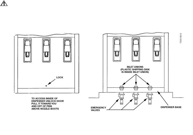
After the concrete has hardened, the dispenser can be set on the island and firmly bolted into place and the product lines connected. To gain access to the bottom section of the dispenser, unlock and remove the doors by pulling out and over the nozzle boots. See Figure 2-2 for an illustration of the dispenser doors.
When installing a blender dispenser, make sure the HI and LO product inlets (and, if applicable, the single product inlet) are correctly located. Refer to the appropriate Installation Instructions in Appendix C.
Remove the shipping discs from the inlet unions and connect the product piping. When making piping connections, to ensure tight, leak-proof connections, wash all cutting oils off the threads and use a UL-classified pipe joint sealing compound, rated for use with petroleum-based products.
WARNING
Explosive or flammable vapors may accumulate within the dispenser housing. All piping connections in the final installation must be accurately fitted and all threaded joints tightly made up with a Listed gasoline-resis- tant pipe joint compound. Put the compound on male threads only, being careful not to get excess inside the pipe or fittings. Failure to perform the above will present a hazardous condition that could result in serious injury.
Figure 2-2 Removal of Dispenser Doors. After removing, place doors in an area where they will not be damaged.
8
Part No. 920365 Rev B |
March 2003 |

2.7Electrical Wiring
2.7.1 General
Wayne recommends employing a qualified electrician for all wiring. A hazardous liquid is being handled, so it is important to ensure that all wiring is in accordance with the National Electrical Code (NFPA 70) as well as all federal, state and local regulations. Note that U.L. requires that all electrical connections to the dispenser be made with threaded, rigid conduit and properly sealed conductors.
NOTE: |
All dispensers and electrical connection boxes must be grounded per NFPA 70. |
Review the location of the dispenser junction box, see Figure 2-3, as well as other parts of the dispenser that may need to be accessed during dispenser installation and start-up.
2.7.2 Full Service (Stand-Alone) Dispenser Wiring
For full service operation, make electrical connections as shown on the appropriate Installation
Wiring Diagram in Appendix C. The electrical connections illustrated are typical when additional like model dispensers are used.
In addition to the required connections for full service operation, the Installation Wiring Diagrams also show optional DATA wires for connecting the dispenser to the Data Distribution Cabinet and the Site Controller Cabinet in a Wayne Control System. These optional data wires are not required for full service (stand-alone) dispensers, however, if a control system may be installed at a later time, the optional data wires shown on the wirng diagrams should be pulled at initial installation. See Section 2.7.5.
NOTE: If optional data wires are run for future use, they should not be physically connected to the data terminals in the dispenser junction box. Instead they should be properly terminated individually using wire nuts .
2.7.3 Submersible Pump Control Relays
Remote dispensers require a relay to control the submersible pump motor. These relays are available as an option with the 2400 MCS and Wayne Plus systems. If the dispenser is not connected to a 2400 MCS or Wayne Plus system, a UL Listed magnetic motor controller assembly, constructed with Potter and Brumfield Relay No. PRD7AYO (120) or equivalent, shall be used.
A maximum of 12 dispensers (24 fueling points) may be connected to a single PRD7AYO (120) relay; other relays may have different limitations. All dispensers operating the same pump control relay must be connected to the same circuit breaker; this may require multiple control relays for a submersible pump.
Ensure that the submersible pump receives its power from its own separate circuit breaker as illustrated in the Typical Site Wiring Diagram 7151-C in Appendix C.
2.7.4 Multiple Dispenser Wiring
A primary requirement in dispenser installation wiring is to provide a means for disconnecting all power connections, including the neutral, to the dispensers for safe shutdown and servicing of the units. Each dispenser could be provided with a separate control Power Circuit Breaker. If this is not desirable or practical, several dispensers can be grouped together and tied to the same Control Power Circuit Breaker as illustrated in Typical Site Wiring Diagram 7151-C in Appendix C. A group of dispensers would then consist of all the dispensers and associated Submersible Pump Control Relay coils supplied by the same Control Power Circuit Breaker.
When more than one dispenser within the group activates the same submersible pump, the Relay Select lines may be commoned at the Submersible Pump Control Relay Coil terminal up to a maximum of 12 connections (24 fueling points). Where more than 12 connections activate the same submersible pump, additional relays should be used and the contacts paralleled as illustrated in 7151-C. In larger installations, dispensers can be separated into multiple groups.
9
March 2003 |
Part No. 920365 Rev B |
 Loading...