

Page 1
Wayne-Dalton Corp.
P.O. Box 67 Mt. Hope, OH 44660
www.wayne-dalton.com
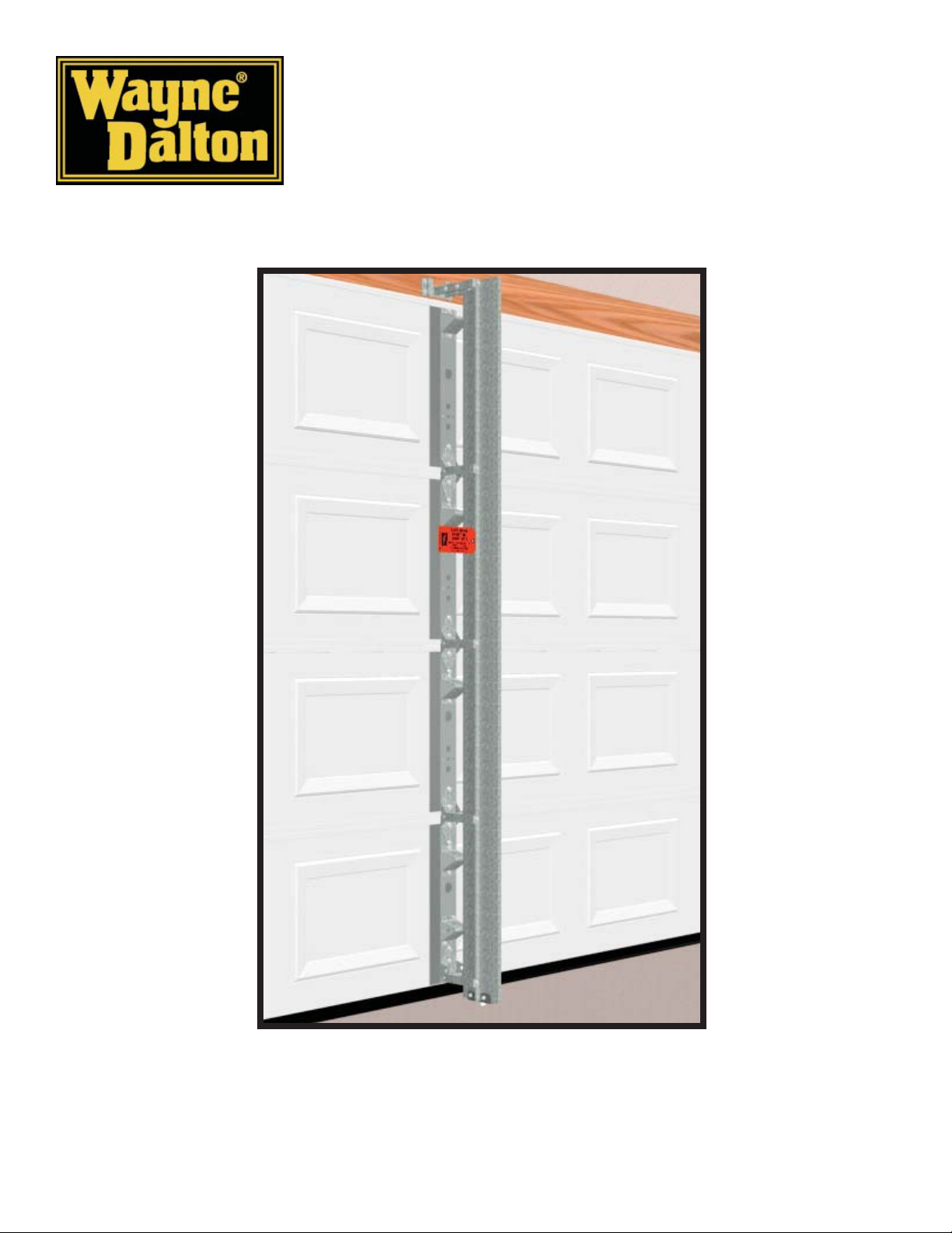
WINDLOAD POST
WayneMark™8000, 8100
INSTALLATION INSTRUCTIONS
See garage door owner’s manual for warranty information.
Important Notice!
READ THE ENCLOSED INSTRUCTIONS MANUAL CAREFULLY BEFORE INSTALLING THIS WINDLOAD
POST. PAY CLOSE ATTENTION TO ALL WARNING LABELS AND NOTES. THIS MANUAL SHOULD BE
ATTACHED TO THE WALL IN CLOSE PROXIMITY TO THE WINDLOAD POST.
© Copyright 2007 Wayne-Dalton Corp. Rev3 6/26/2007
307330
Page 2
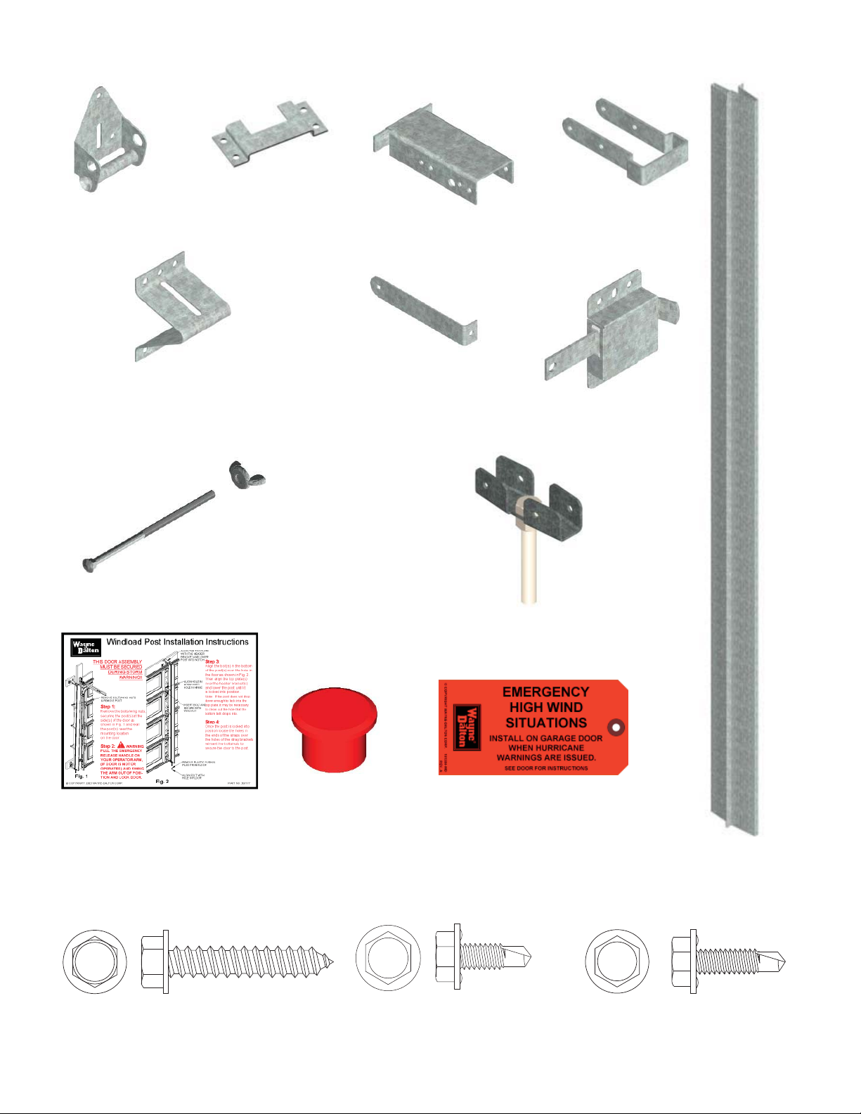
HEADER LOCK BRACKET
HALF HINGE
(2) # 130352
JR. UNIVERSAL “A” FRAME BRACKET
(5) # 270343 w/ 7’ kit
(6) # 270343 w/ 8’ kit
CARRIAGE BOLTS
(3) # 305210 w/ 7’ kit - (3” LG)
(4) # 305210 w/ 8’ kit- (3” LG)
(1) #307529 w/ 7’ & 8’ kit’s - (3-1/2” LG)
(2) # 141092
WING NUTS
(4) # 305211 w/ 7’ kit
(5) # 305211 w/ 8’ kit
TOP PLATE EXTENSION
(1) # 305205
STRAPS
(8) # 307397 w/ 7’ kit
(10) #307397 w/ 8’ kit
TOP STRAP BRACKET
(1) # 305206
(1) SIDE LOCK
# 292857
(1) POST INSTALLATION DECAL
# 307177
(8) 5/16” X 1-5/8” LAG SCREW
# 100292
(1) PLASTIC PLUG
# 305226
SELF-DRILLING SCREW
(1) BOTTOM BRACKET ASSEMBLY
# 305327
(1) POST TAG
# 161384
WINDLOAD POST ASSEMBLY
(34) 1/4-20 X 11/16”
# 300723
# 305207 - (7’)
# 305332 - (8’)
(6) 1/4-20 X 7/8”
SELF-DRILLING SCREW
# 100507
2
Page 3
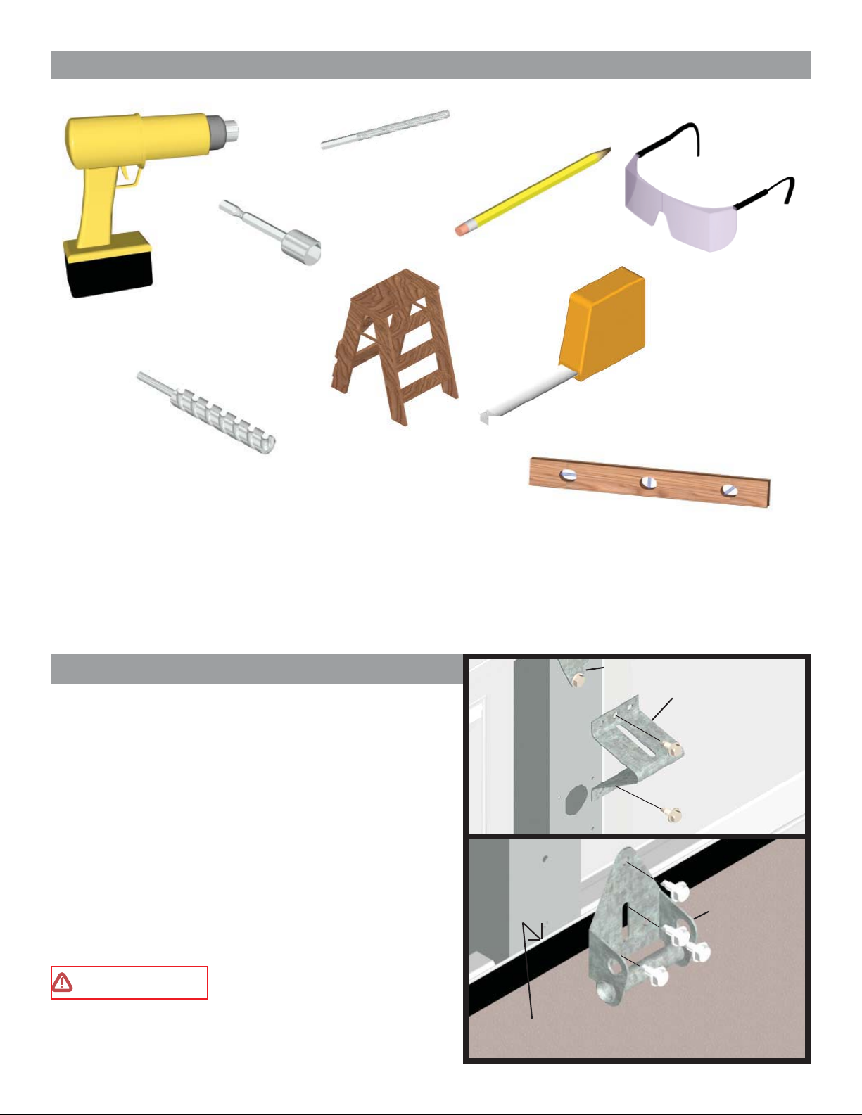
Required Tools
(1) 3/16” DRILL BIT
PENCIL
(1) 7/16” HEX
DRILL
(1) 5/8” X 4”
MASONRY DRILL BIT
HEAD DRIVER
STEP LADDER
Windload Post Installation
JR. “A” Frame Installation
IMPORTANT! Refer to the windload specifi cation draw-
ings (supplied) for windload post location(s).
FIG. 1
SAFETY GLASSES
TAPE MEASURE
LEVEL
CENTER HINGE
JR. “A” FRAME
Place the “A” frame brackets below the center hinges of
each intermediate section, fasten with (2) 1/4-20 x 11/16”
self drilling screws (see Fig.1). For the bottom section, align
half hinge with top edge of astragal retainer and center on
stile(s). Fasten half hinge with (4) 1/4-20 x 11/16” self-drilling screws (see Fig.1A). Center all brackets in the required
positions per the windload specifi cation drawings.
NOTE: Additional Jr. “A” frame brackets are required
for 10’ and 12’ wide doors.
WARNING
“A” FRAME BRACKETS MUST
BE INSTALLED ACCORDING TO THE WINDLOAD
SPECIFICATION DRAWINGS, OR DOOR FAILURE
WILL OCCUR UNDER WINDLOAD
.
3
(2) 1/4-20 X 11/16”
SELF-DRILLING SCREW
FIG. 1A
HALF HINGE
(4) 1/4-20 X 11/16”
SELF-DRILLING SCREW
EDGE OF
ASTRAGAL RETAINER
Page 4

Header Lock Bracket Installation
Mark a vertical line on the header, aligned with the
CENTER
LINE
HEADER
center of the Jr. “A” frame bracket. Measure up 1-1/2”
above the top of the door and mark a horizontal line.
1-1/2”
Center the header lock bracket with the vertical line
and align the bottom of the header lock bracket with
the horizontal line. Secure the header lock bracket to
HEADER LOCK
BRACKET
the header using (4) 5/16” x 1-5/8” lag screws.
(see Fig. 2)
(4) 5/16” X 1-5/8”
LAG SCREWS
FIG. 2
NOTE: It is recommended that lag screws be pilot
drilled using a 3/16” drill bit prior to fastening.
IMPORTANT! If there is drywall or other materials covering the header it is required that such materials be
removed from the header lock bracket location(s) and replaced with the same thickness of wood before installing
the header lock bracket(s). If this process is performed, the length of the lag screws MUST be increased by the
thickness of wood material, so that a minimum of 1-1/2” penetration into the existing header is obtained.
Bottom Bracket Installation
FIG. 3
Locate the bottom bracket assembly and align it to the
bottom of the post. Secure the bottom bracket to the
bottom of the windload post using (4) 1/4-20 x 11/16”
self-drilling screws. (see Fig. 3)
NOTE: The bottom of the windload post is fl ush
while the top is offset.
Post Hole Placement
At each windload post location, mark a center line on
(4) 1/4-20 X 11/16”
SELF-DRILLING
SCREWS
BOTTOM
BRACKET
ASSEMBLY
the fl oor that is aligned with the center of half hinge.
Measure out from the back of the door (see Fig. 4) 5-3/4”
and make a second mark as shown in Fig. 5. Using a masonry bit, drill (1) 5/8” x 4” deep hole into the concrete.
Clean out the hole.
IMPORTANT! For proper operation of the windload
post, it is important that the 5-3/4” dimension be held,
FIG. 5
to assure the post is installed plumb.
DIM. 5-3/4”
FIG. 4
4
DIM. 5-3/4”
DO NOT MEASURE
FROM BOTTOM SEAL
(SEE FIG.4)
CENTER LINE
OF HALF HINGE
5/8” X 4”
DEEP HOLE
Page 5

Top Plate Extension Installation
Locate the top plate extension and top strap bracket. Place the top strap bracket onto the top plate extension and
adjust so that the holes in the top strap bracket align with the corresponding door model holes in the top plate
extension. Hold in position and secure using (4) 1/4-20 x 7/8” self-drilling screws. (see Fig. 6)
Slide the top plate extension assembly into the header bracket. Now, install the windload post into the post hole
in the fl oor and align the top of the windload post with the top plate extension assembly. Ensure that the post is
level and plumb. Using (2) 1/4-20 x 7/8” self-drilling screws, secure the windload post to the top plate extension
assembly. (see Fig. 7)
NOTE: Doors without a 2” U-bar on the top section will require an extra Jr. “A” frame bracket, at the top
of the section. (see Fig. 7).
TOP PLATE
EXTENSION
(4) 1/4-20 X 7/8”
SELF-DRILLING
SCREWS
FIG. 6
TOP STRAP
BRACKET
TOP PLATE
EXTENSION
ASSEMBLY
(2) 1/4-20 X 7/8”
SELF-DRILLING
SCREWS
JR. “A”
FRAME
FIG. 7
5
Page 6

Strap Bracket Installation
Loosely attach (2) straps to each center hinge, with (1)
3” long carriage bolt and wing nut (see Fig. 8). Attach
(2) straps to the bottom half hinge, with (1) 3-1/2” long
carriage bolt and wing nut (see Fig. 9). Position the straps
at each center hinge, and bottom half hinge locations.
Ensure that the windload post is plumb while locked into
the header lock bracket and hole in fl oor. Now, secure
each strap to the windload post using (1) 1/4-20 x 11/16”
self-drilling screw.
CENTER
HINGE
WING
NUT
(2) STRAP
NOTE: Keep straps parallel and level. (see Fig. 10)
Finish hand tightening the carriage bolts and wing
FIG. 9
WING
NUT
HALF HINGE
(2)STRAPS
3-1/2” LG.
CARRIAGE BOLT
Side Lock Installation
3” LG.
CARRIAGE BOLT
STRAP
JR. “A”
FRAME
FIG. 8
FIG. 10
WINDLOAD
POST
(2) 1/4-20 X 11/16”
SELF-DRILLING SCREWS
Install side lock on the second section from the bottom
of the door. Square side lock assembly with door section and hole in vertical track. The side lock should be
spaced approximately 1/8” from the section edge. Secure
the side lock to the section with (4) 1/4-20 x 11/16” self
drilling screws.(see Fig. 11)
IMPORTANT! Side locks and openers should not be
engaged at the same time. If an opener is installed on
the door and engaged, be sure side locks are disengaged,
otherwise damage could result to door and/or opener.
Only use side locks when opener is disengaged from
the garage door.
ALIGN WITH
HOLE IN
VERTICAL
TRACK
6
1/8”
FIG. 11
SIDE LOCK
(4) 1/4-20 X 11/16”
SELF DRILLING
SCREWS
Page 7

Securing Post for Storage
Locate a convenient place to store the windload post(s).
Measure and cut (2) 2” x 6” wood mounting blocks a
minimum of 10” long for each windload post. Locate
the mounting blocks horizontally on the wall as shown
in Fig. 12. Secure them adequately to the wall at the top
and bottom of the post storage location, with masonry
anchors for concrete construction, or 16 penny nails for
wood construction. Measure a distance of 6” greater than
door height as illustrated in Fig. 12, and mount the extra
header lock bracket(s) to the top mounting block(s) using
(2) 5/16” x 1-5/8” lag screws as shown in Fig. 12.
TOP OF WINDLOAD POST
JR. “A”
FRAME
MEASURE THE
DISTANCE FROM THE
TOP OF THE WINDLOAD
POST TO THE CENTER
OF THE BOTTOM STRAP
Measure the distance from the top of the windload post
to the center of the bottom strap (see Fig. 13). Use that
measurement for the dimension between the center of
the extra header lock bracket and half-hinge tube. Position the half-hinge on the bottom mounting block and
secure the half-hinge using (2) 5/16” x 1-5/8” lag screws.
Repeat this step for remaining windload posts if necessary. (see Fig. 12)
HEADER LOCK
BRACKET
6” MIN.
(2) 5/16” X 1-5/8”
LAG SCREWS
DISTANCE BETWEEN TOP
OF WINDLOAD POST AND
CENTER OF BOTTOM
STRAP
HALF
HINGE
BOTTOM
STRAP
FIG. 13
BOTTOM OF
WINDLOAD POST
HALF-HINGE
TUBE
(2) 5/16” X 1-5/8”
LAG SCREWS
FIG. 12
Slide the windload post(s) into storage header bracket(s)
and secure the bottom strap(s) to the half hinge(s) using
the 3-1/2” carriage bolt and wing nut. Place all remaining
wing nuts and carriage bolts into the remaining straps for
storage. Insert plastic plug into hole in fl oor.
7
Page 8

Attaching the Installation Decals
After the installation is complete, locate in a obviously visible location on the inside of the garage door and the
post(s) and place the provided installation labels and tag(s) onto the door and post(s) for future reference.
IMPORTANT! LABELS AND TAG(S) MUST BE ATTACHED TO BOTH DOOR AND POST(S).
Windload Label Locations
2
1
3
1 Applied by Installer - One (1) Emergency High Wind Situations Tags
(161384) per post -Tags are to be applied to post(s) when stored on
wall for constant reminder to consumer.
2
3
Applied by Installer - One (1) Windload PSF Label per post, based
on the required design PSF load. Label is to be applied to windload
post for reference.
Applied by Installer - One (1) Windload Post Installation Instructions
Label (307177) -Only on doors specifi ed with one or more posts. To be
applied to inside of door, next to endcap of second section on side of the
door where Post no. 1 is stored.
MAKE SURE LABELS AND TAG(S) LIKE THE ONES ABOVE ARE INSTALLED ON THE DOOR
AND POST(S)!
CONTACT WAYNE-DALTON CORP. FOR A FREE REPLACEMENT DECAL.
Please Do Not Return This Product To The Store.
Contact your local Wayne-Dalton dealer. To fi nd your local Wayne-Dalton dealer, refer to your
local yellow pages/business listings or go to the Find a Dealer section online at www.wayne-dalton.com
8
 Loading...