

Page 1

RO L L I N G G R I L L E S
600
W A Y N E - D A L T O N C O M M E R C I A L D O O R S Y S T E M S
6 0 0 S E R I E S
ROLLING GRILLES
DURABLE ROLLING GRILLES WITH MULTIPLE BENEFITS
Wayne-Dalton Rolling Grilles offer total security, visibility, and
ventilation in a number of patterns and finishes for commercial,
industrial, retail, and institutional applications. These grilles are
available in steel, aluminum, or stainless steel to meet any need.
• SIZES UP TO 42' WIDE AND
26' HIGH
• VARIETY OF PATTERNS AND
MATERIALS
• EXTREMELY DURABLE
CONSTRUCTION
Page 2
ROLLING GRILLES
600 SE RIES
Wayne-Dalton Rolling Grilles are designed to maximize
security, visibility, and ventilation.The durable construction
technique used ensures that the grilles will offer many
years of reliable and consistent performance.
Materials & Construction
Standard features include 5/16” galvanized steel horizontal
rods, continuous from jamb to jamb, and covered with
aluminum tubes. Vertical links are aluminum. End links
ensure that the grille cannot be pulled from guides.
The bottom bar is a tubular aluminum extrusion, fitted
with nylon end caps which act as bearing surfaces.
Optional cylinder lock assembly in bottom bar activates
concealed 3/8” steel tamperproof lock rods. Lock uses
standard mortise cylinder, and is also available with an
optional removable core. Center locks available up
to 25' wide.
Aluminum grill patterns are available in clear, mill, or
bronze anodized finishes. Optional materials are #304
finished stainless steel and galvanized steel.
Powder coating is available in 180 colors. Powder coating
is a dry finishing process in which finely ground particles
of pigment and resin are electrostatically charged and
sprayed onto the electrically grounded parts of rolling
doors.These charged particles adhere to the rolling door
parts until they melt and fuse into a solid coating in a
curing oven.The result is a finish that radiates beauty and
smoothness for an aesthetically pleasing grille.
Operation can be manual push-up, chain, crank, or
motor-operated. Door mounting can be self-supporting,
using structural tubes, or directly to the building structure.
Counterbalance assembly consists of a spring
barrel which serves as a load-carrying beam. It
encases the counterbalance mechanism and
provides the axis around which the curtain coils.
(Deflection is limited to 0.033" per lineal foot of
span.) If required, barrel rings of malleable iron or
stamped steel may be provided to assure proper
countebalance. Oil-tempered, torsion-type
counterbalance springs are wound from
heat-treated steel, providing accuracy in balancing
the door. Barrel plugs connect ends of springs to
barrel and tension rod. Tension rod of steel
shafting holds fixed ends of springs and carries
torsional load of spring counterbalance.
Spring tension adjusting wheel is normally mounted
outside the bracket on end of tension rod. Inside
adjusting wheel for tight side-room applications is
available in limited sizes.
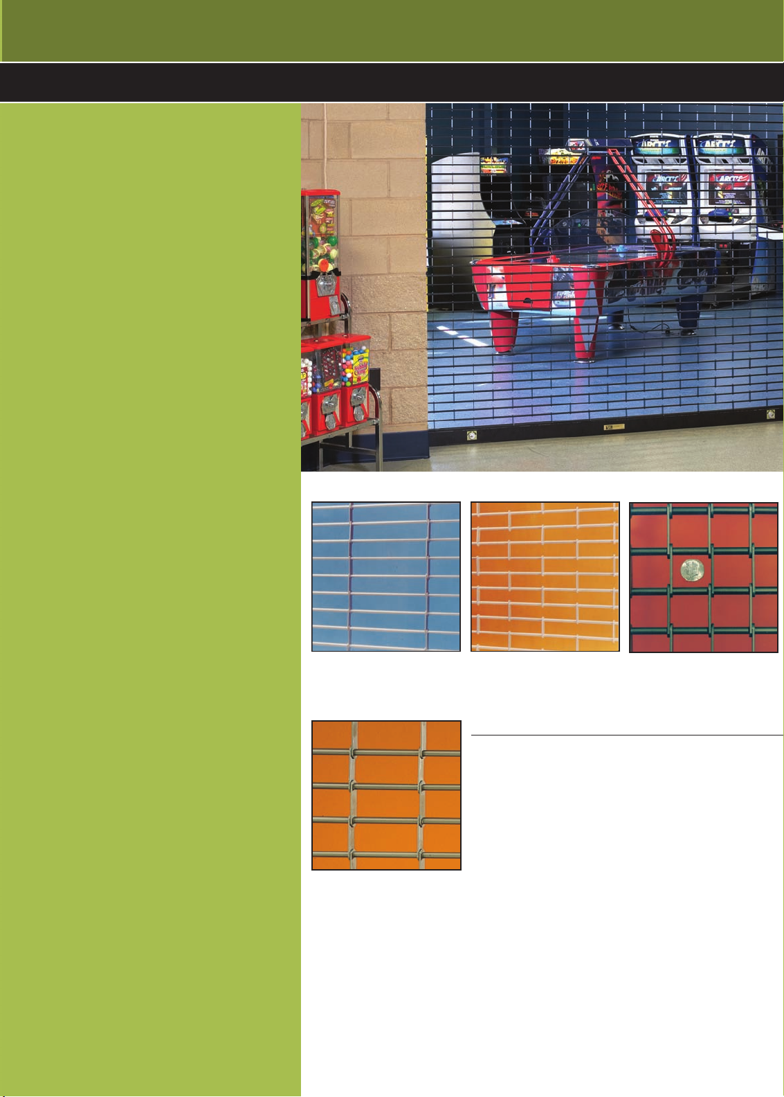
Available patterns
G6 Pattern (standard)
For aluminum, galvanized and
stainless steel.
G8 Pattern (optional)
Designed with closer spacing
of vertical links, but wider
than G7 pattern.
G1 Pattern (optional)
For aluminum, galvanized and
stainless steel.
Options
• Steel MountingTubes
• Lexalite Inserts
• Centerlock Security Pattern
• Sloped Bottom Bars
• Drop Stop Device
• Safety Edges
• Powder Coating
• Cable Releases
• Super-Imposed Combination Doors
• Multiple Locking Combinations
• Emergency egress available on motor operated doors
G7 Pattern (optional)
Designed with closer spacing of vertical
links (2"). Shown in bronze anodized
aluminum. Note: dime shown for scale.
Optional hood cover encloses curtain coil and
counterbalance mechanism and is made to match
the grille finish.
www.wayne-dalton.com/commercial
Page 3

ROLLING GRILLES
LINTEL
HOOD OPTIONAL
6"
7"
WHEEL
ADJUSTING
W
OPENING HEIGHT
3" X
Y
BRACKET HEIGHT
6"
8"
LINTEL
WHEEL
ADJUSTING
HOOD OPTIONAL
X
OPENING HEIGHT
3"
Y
BRACKET HEIGHT
MANUAL OPERATION
CHAIN HOIST OPERATION
SECTIONELEVATION
SECTION (FACE MOUNTED)ELEVATION
BETWEEN JAMBS
BETWEEN JAMBS WITH PACK OUT ANGLES
FACE MOUNTED
COMMON GUIDE MOUNTING OPTIONS
CLEAR OPENING
OPENING WIDTH
STEEL MOUNTING
MASONRY MOUNTED
.25".25"
CLEAR OPENING
PACK OUTANGLES
2.25"
5.25"
2.25"
4.25"
CLEAR OPENING
OPENINGWIDTH
600 SE RIES
Page 4

ROLLING GRILLES
AWNING CRANK OPERATION
MOTOR OPERATION
6"
7"
LINTEL
WHEEL
ADJUSTING
HOOD OPTIONAL
Y
OPENING HEIGHT
3" X
BRACKET HEIGHT
W
26.5"
3"
16"
CLEAR OPENING
X
Y
BRACKET HEIGHT
POWER
UNIT
W
BRACKET HEIGHT
16"
Y
26"
X3"
OPENING HEIGHT
POWER
UNIT
8"
6"
WHEEL
ADJUSTING
HOOD OPTIONAL
LINTEL
SECTION (FACE MOUNTED)ELEVATION
SECTION (BETWEEN JAMBS) SECTION (FACE MOUNTED) ELEVATION (POWER UNIT)
600 SE RIES
Page 5

ROLLING GRILLES
600 SE RIES
Aluminum Grilles
WIDTH HEIGHT
30' 6'0" 14" 14" 14-1/2" 17" SEE SKETCH SEE SKETCH
30' 7'1" 15" 15" 15-1/2" 18" SEE SKETCH SEE SKETCH
30' 7'11" 16" 16" 16-1/2" 19" SEE SKETCH SEE SKETCH
30' 10'4" 17" 17" 17-1/2" 20" SEE SKETCH SEE SKETCH
30' 12'0" 18" 18" 18-1/2" 21" SEE SKETCH SEE SKETCH
30' 14'6" 19" 19" 19-1/2" 22" SEE SKETCH SEE SKETCH
25' 18'0" 20" 20" 20-1/2" 23" SEE SKETCH SEE SKETCH
30' 17'2" 20" 20" 20-1/2" 23" SEE SKETCH SEE SKETCH
25' 20'0" 21" 21" 21-1/2" 24" SEE SKETCH SEE SKETCH
30' 18'0" 21" 21" 21-1/2" 24" SEE SKETCH SEE SKETCH
30' 20'0" 23" 23" 23-1/2" 26" SEE SKETCH SEE SKETCH
BRACKET
SIZE
X Y W R L
Steel Grilles and Stainless Steel Grilles
WIDTH HEIGHT
30' 7'0" 16" 16" 16-1/2" 19" SEE SKETCH SEE SKETCH
30' 10'0" 17" 17" 17-1/2" 20" SEE SKETCH SEE SKETCH
30' 7'11" 16" 16" 16-1/2" 19" SEE SKETCH SEE SKETCH
30' 12'0" 18" 18" 18-1/2" 21" SEE SKETCH SEE SKETCH
26' 15'0" 19" 19" 19-1/2" 22" SEE SKETCH SEE SKETCH
30' 14'0" 19" 19" 19-1/2" 22" SEE SKETCH SEE SKETCH
28' 18'0" 20" 20" 20-1/2" 23" SEE SKETCH SEE SKETCH
30' 17'0" 20" 20" 20-1/2" 23" SEE SKETCH SEE SKETCH
16' 20'0" 21" 21" 21-1/2" 24" SEE SKETCH SEE SKETCH
25' TO 30' 18'0" 21" 21" 21-1/2" 24" SEE SKETCH SEE SKETCH
30' 20'0" 23" 23" 23-1/2" 26" SEE SKETCH SEE SKETCH
BRACKET
SIZE
X Y W R L
NOTE: Dimensions are for general reference
only and not for construction purposes.
Page 6

ROLLING GRILLES
6 0 0 S E R I E S
Note to specifiers: Words in brackets indicate frequently specified and highly recommended options.
PART I – GENERAL
1.01 Work Included
A. The opening will be equipped withWayne-Dalton
600 Series rolling grilles.
1.02 Related Work
A. Opening preparation,miscellaneous or structural metal
work,access panels,finish or field painting,field
electrical wiring,wire,conduit,fuses,and disconnect
switches are in the ScopeofWork of other divisions
or trades.
1.03 Reference Standards
A. ANSI/DASMA203–American National Standards
Institute Specifications for non-ratedfire rolling doors
published by Door & AccessSystems Manufacturers
Association International.
B. ASTM A123 – Zinc [hot-dipped galvanized] coat-
ings
on iron andsteel products.
C. ASTMA229– Steel wire,oil-tempered for
mechanical springs.
D. ASTM A-653-94– Steel sheet,zinc-coated
[galvanized] by the hot-dipped process,
commercial quality.
1.04 Quality Assurance
A. Rolling grilles and all accessories and components
required for completeand secureinstallations shall be
manufactured as a system from one manufacturer.
1.05 Systems Description
A. Rolling Grille:Type:
Model 600
B. Mounting:[steel] [wood] [masonry] jambs
C. Operation: [manual push-up] [crank] [chain hoist]
[motor] [motor with chainhoist]
D. Material:[Galvanized steel] [aluminum] [stainless steel]
1.06 Submittals
A. Shop Drawings:Clearly indicate the following:
1. All details required for complete operation
and installation.
2. Hardware locations.
3. Type of metal and finish for door sections.
4. Finish for miscellaneous components and
accessories.
B. Product Data:Indicating manufacturer’s product
data,and installation instructions.
Because of continuing product improvements,we reserve the right to change the product specifications and designs without prior notice.
1.07 Delivery, Handling, Storage
A. Deliver products in manufacturer’s original containers,
dry,undamaged,seals and labelsintact.
B. Store and protect products in accordance with
manufacturer’s recommendations.
1.08 Warranty
A. Standard manufacturer’s one year warranty against
defects in material and workmanship.
PART I I – PRODUCTS
2.01 Curtain
A. Curtains are to be fabricated of 5/16" galvanized
steel horizontal rods, continuousfrom jamb to jamb,
coveredwith aluminum tubes.Vertical links and tubes
available in stainless,aluminum or galvanized steel. End
links insure that grille cannot be pulled from guides.
2.02 Guides
A. Guides will be of extruded aluminum with woolpile
inserts to contact both faces of grille,actingaswearing
surfacesand sound deadener.
2.03 Brackets
A. Bracket Plates will be of 3/16”minimum[1/4”] steel
plate. Sealed ball bearings to support the
counterbalance assembly.Brackets to form end
closures and support hoods.
2.04 Counterbalance
A. Curtain to be coiled on a pipe of sufficient size to
carry door load with deflection not to exceed .033"
per foot of door span and to be correctly balanced by
helical springs,oil tempered torsion type. Cast iron
barrel plugs will be usedtoanchor springs to tension
shaft and pipe.
2.05 Hood
A. When required,hood is to be fabricated of 24-gauge
galvanized steel (stainless steel) (20 B&S gauge
aluminum).Provide intermediate hood supports over
16'0" opening width.
2.06 Finish
Finish for aluminumsurfaces is to be (mill) (clear
anodized204R1)(bronze anodized).Non-galvanized
steel surfaces are to be painted one shop coat of rust
inhibiting primer.Stainless steel to be #304 brushed.
2.07 Operation
A. Grilles will be operated by means of (manual,with lift
handles)(by chain and gear–maximum pull of 35 lbs.)
(by fully enclosed awning type crank gearing and
removable crank arm) (by motoroperator).
2.08 Locking
A. Manual or crank operated grilles to be by means of
slide bolt locking device operable from inside or
outside.Chain lock keeperonchain operated doors.
Motor operated grillestoinclude self-locking gearing
plus chain locking device for emergency chain.
Note: When specifying locks on electric-motor operated
doors,electric interlocks should also be specified to
preventoperation when lock bolts are engaged in the
guides,thus preventing damage to the curtain
and/or operator.
PART III – EXECUTION
3.01 Installation
A. General:
1. Install grilles in accordance withmanufacturer’s
2. Verify that existing conditions are ready to receive
3. Beginning of rolling grille work means acceptance
B. Installgrille complete with necessaryhardware,jamb
and head mold strips,anchors,inserts, hangers, and
equipment supports in accordance with final shop
drawings,manufacturer’s instructions,and as specified
herein.
C. Fit,align and adjust rolling grilleassemblieslevel and
plumb for smooth operation.
D. Upon completionof final installation,lubricate,test and
adjust grilles to operateeasily,freefrom warp,twist or
distortion and fitting for entire perimeter.
Note: Architect may consider providing a schedule when
more than one rolling grille or opening type is
required.
instructions and standards.Installation shall be by an
authorizedWayne-Daltonrepresentative.
rolling grille work.
of existingconditions.
Distributed By:
For technical information, visit:
www.wayne-dalton.com/commercial
© 2008 Wayne-Dalton Corp. • One Door Drive • Mt. Hope, Ohio 44660 • 800-255-3046
Mt. Hope, OH • Dalton, OH • Trail, OH • Pensacola, FL • Portland, OR
Printed in U.S.A.
Item #333072 Revised 4/2008
 Loading...