

Page 1
Model 451/452
Aluminum FullView
COMMERCIAL GARAGE DOOR INSTALLATION
INSTRUCTIONS AND OWNER’S MANUAL
Read these instructions carefully before attempting installation. If in
question about any of the procedures, do not perform the work. Instead,
have a trained door systems technician do the installation or repairs.
IMPORTANT
SAFETY NOTICES
An overhead door is a large heavy object that moves with the help of springs under high tension. Moving objects and springs under tension
can cause injuries. For your safety and the safety of others, follow these instructions:
1. Wear protective gloves during installation to avoid possible cuts from sharp metal edges.
2. It is always recommended to wear eye protection when using tools, other wise serious eye injury could result.
3. Operate door ONLY when properly adjusted and free of obstructions.
4. Keep door in full view while operating it. Watch the door open or close completely before leaving the area.
5. Should the door become hard to operate or completely inoperative, a qualifi ed door agency should correct the problem to prevent
damage to the door or serious personal injury.
6. DO NOT PERMIT children to play with the garage door or the electrical controls. Fatal injury could result, should the child become
entrapped between the door and the fl oor.
7. To prevent serious injury or death, avoid standing in the open doorway or walking through the doorway while the door is moving.
8. Use lift handles/step plate when manually operating the door. DO NOT place fi ngers into section joints when operating the door.
9. Remove pull rope if door is operated by an electric opener.
10. Door is constantly under EXTREME SPRING TENSION. To prevent possible serious injury or death, adjustments, repairs, removal, or
installation, ESPECIALLY of SPRING ASSEMBLIES, CABLES, or BOTTOM BRACKETS, should be performed ONLY by qualifi ed door
service people.
11. Check door and its hardware monthly for loose, worn, or broken parts. Have any repairs or adjustments made by a qualifi ed door agency.
12. Have the door professionally inspected once a year.
13. Lubricate hinges, springs and rollers once a year.
This manual MUST be attached to the wall in close proximity to the door.
Copyright 2008 Wayne-Dalton Corp. Part No. 338306 New 5/27/2008
Page 2
OPERATING ZONE
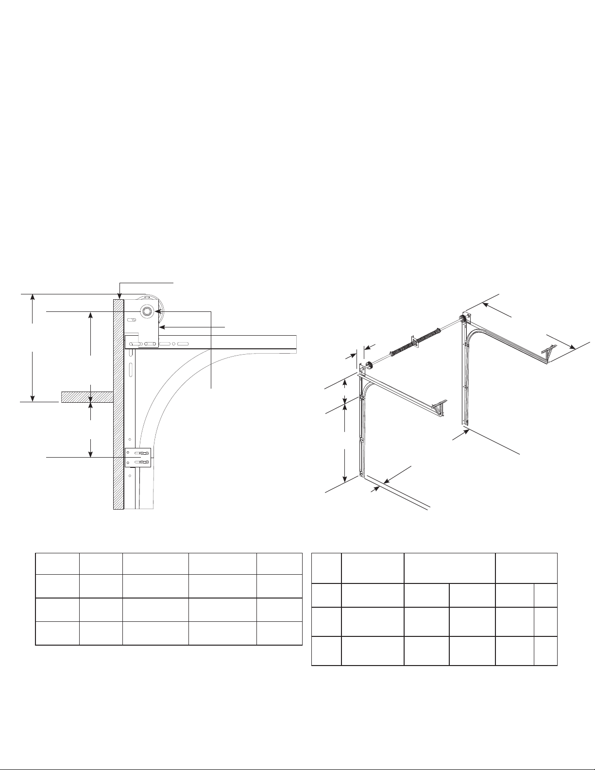
You Can Save Time And Effort If You First Establish All The Facts About The “Operating Zone”. The “ Operating Zone” is the area surrounding the door opening, extending upward and
backward as far as the door will travel. We call it the Operating Zone because it is the area that the door will have to operate within and the dimensions are critical and must be known in
advance of a door and operator installation.
1. Daylight Opening: Exact size of fi nished opening.
2. Sideroom: required distance from the door opening to a wall or any obstruction. Refer To Sideroom Requirements.
3. Headroom: required distance from top of door opening to the ceiling or underside of joists. Refer To Headroom Chart.
4. Backroom: required distance from door opening header to the furthest back point to which the door track or operator unit, and their
brackets, will extend. Refer to Backroom Chart.
Verify the operating zone dimensions.
1 - Exact size of fi nished daylight opening. Do you have the correct door size?
2 - Sideroom requirements for track and spring shaft. (Refer to sideroom chart)
3 - Headroom requirements. (Refer to headroom chart for standard lift track)
4 - Backroom (depth into room) Manual lift = Door height plus 18” ; Operators = Door height plus 48” (Standard Lift)
5 - Jambs must be plumb and solidly attached to the building. Floor must be level or exact gradeline established before you start.
Shipping tags show important information, door size, track size and type, spring size and hardware type. Verify that all material is present and correct before attempting installation.
EXTEND JAMBS TO OPENING HEIGHT
PLUS DIM Y PLUS 1-1/2” (MINIMUM LENGTH)
MINIMUM HEADROOM
REQUIRED (REFER TO
HEADROOM CHART)
DIM “Y” HEADER
TO SHAFT
CENTERLINE
8” FOR 2” TRACK
12” FOR 3” TRACK
HEADROOM CHART For Standard Lift Track (Minimum Distance Required)
DRUMS DIMS
400-8,
400-12
5250-18
800-32
Dim. Y INDICATES THE DISTANCE FROM THE HEADER TO THE CENTER LINE OF
TORSION SHAFT.
NOTE: 2 1/2” OF ADDITIONAL HEADROOM IS REQUIRED FOR SINGLE TROLLEY
OPERATOR INSTALLATIONS.
NOTE: HEADROOM CAN BE REDUCED 2-1/2” BY USING THE QUICK CLOSING TOP
FIXTURE OR BY SHORTENING THE VERTICAL TRACKS BY 3” MAX.
HEADROOM
DIM Y
HEADROOM
DIM Y
HEADROOM
DIM Y
3” TRACK, 15”
RADIUS
15-1/2”
13”
19”
14-1/2”
21”
16-1/2”
WALL ANGLES CUT 3” OFF
FOR 12” RADIUS APPLICATIONS
TORSION SHAFTS REQUIRE 10” OF
SIDEROOM FOR SOLID SHAFTS AND 5” OF
SIDEROOM FOR TUBULAR SHAFTS
2” TRACK, 15”
RADIUS
14-1/2”
12”
18”
13-1/2”
20”
15”
2” TRACK,
12” RADIUS
12-1/2”
9”
15”
10-1/2”
17”
12-1/2”
SIDE ROOM “B”
HEADROOM “Y”
DAYLIGHT
OPENING HEIGHT
SIDE ROOM “A”
BACKROOM CHART (Minimum Distance Required)
TRACK
SIZE
MANUAL DEPTH
2”
MOTOR PLUS 66”
3”
MOTOR PLUS 66”
INTO ROOM
DOOR HEIGHT
PLUS 18”
DOOR HEIGHT
PLUS 24”
BACKROOM
DAYLIGHT
OPENING WIDTH
DIM. A
SIDEROOM TRACK
STEEL
3-1/2” 4” 10” 5”
4” 5” 10” 5”
MASONRY
AND WOOD
DIM. B
SIDEROOM
TORSION SHAFT
SOLID TUBE
2
Page 3
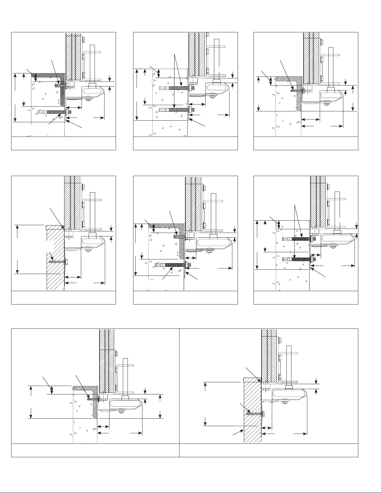
SIDEROOM REQUIREMENTS
5/16 X 1” DRILLING/
TAPPING SCREW
1” OVERLAP
SIDE ROOM
3-1/2” MIN.
4-3/4”
3/8 X 3” MIN.
SLEEVE ANCHOR
PRECAST WALL WITH CORNER ANGLE
FLUSH
1-1/2”
2” TRACK
4-3/16”
OPTIONAL
MOUNTING
BRACKET
1/2”- 5/8”
1/2”- 5/8”
3/8 X 3” MIN.
SLEEVE ANCHOR
1” OVERLAP
SIDE ROOM
3-1/2” MIN.
4-3/4”
PRECAST WALL WITHOUT CORNER ANGLE
5/16 X 1” DRILLING/
TAPPING SCREW
1” OVERLAP
1-1/2”
2” TRACK
4-3/16”
OPTIONAL
MOUNTING
BRACKET
1/2”- 5/8”
1/2”- 5/8”
5/16 X 1” DRILLING/
TAPPING SCREW
1” OVERLAP
SIDE ROOM
3-1/2” MIN.
3/8 X 3” MIN.
SLEEVE ANCHOR
1” OVERLAP
1/2”- 5/8”
4-1/2
MIN.
1-1/2”
4-3/16”
STEEL JAMBS
2” TRACK
1/2”- 5/8”
5/16 X 1-5/8”
LAG SCREW
4” MIN.
SIDE ROOM
2” X 6” JAMB IS
RECOMMENDED
1” OVERLAP
4” MIN.
SIDE ROOM
1-1/2”
WOOD JAMBS
2” TRACK
5/16 X 1” DRILLING/
TAPPING SCREW
4-3/16”
STEEL JAMBS
3” TRACK
1”
4-15/16”
4” MIN.
SIDE ROOM
5-1/2”
3/8 X 3” MIN.
SLEEVE ANCHOR
PRECAST WALL WITH CORNER ANGLE
1/2”- 5/8”
5-1/2”
MIN.
MOUNTING BRACKET
3” TRACK
1-1/2”
4-15/16”
OPTIONAL
5/16 X 1-5/8”
LAG SCREW
SIDE ROOM
5-1/2” MIN.
2” X 6” JAMB
IS RECOMMENDED
FLUSH
4” MIN.
SIDE ROOM
5-1/2”
PRECAST WALL WITHOUT CORNER ANGLE
1”
4-15/16”
WOOD JAMBS
3” TRACK
3” TRACK
1/2”- 5/8”
1-1/2”
4-15/16”
OPTIONAL
MOUNTING
BRACKET
3
Page 4
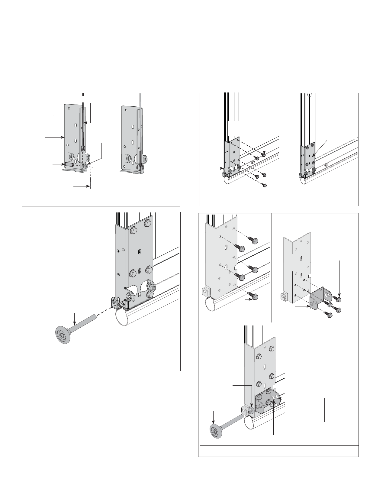
COUNTERBALANCE CABLES/ BOTTOM BRACKETS
For doors using the broken cable safety device, see page 19.
For Model 451 doors with the bottom bracket shown in FIG A, locate the bottom section and the left and right hand bottom brackets. Secure the counterbalance cables to the brackets using
clevis pin, washer and cotter key as shown in FIG A. Secure bottom brackets to bottom section using (5) 1/4” x 7/8” self-drilling screws as shown in FIG B. Insert a roller into the bottom
brackets as shown in FIG C.
For Model 451 doors with the bottom bracket shown in FIG D, Secure the counterbalance cables in the same manner as described above. Attach the bracket to the section with (5) 1/4” X
7/8” self drilling screws. Attach the roller carrier to the bottom bracket with (4) 1/4” X 7/8” self drilling screws. Insert a roller and 3/16” roller spacer into the roller carrier; the inner holes of
the roller carrier are for 2” track; the outer holes of the roller carrier are for 3” track.
COUNTERBALANCE CABLE
BOTTOM BRACKET
CLEVIS PIN
COTTER KEY
WASHER
FIG A
BOTTOM
BRACKET
ASSEMBLY
BOTTOM
SECTION
(5) 1/4” X 7/8” SELF
DRILLING SCREWS
BOTTOM
SECTION
ATTACHED
BOTTOM BRACKET
ASSEMBLY
FIG B
(4) 1/4” X 7/8” SELF
DRILLING SCREWS
ROLLER
(5) 1/4” X 7/8” SELF
DRILLING SCREWS
ROLLER CARRIER
FIG C
3/16”
ROLLER
SPACER
ROLLER
OUTER HOLES FOR 3” TRACK
INNER HOLES FOR 2” TRACK
FIG D
4
Page 5
HINGES
NOTE: Top sections do not require hinges.
Use the ENDHINGE CHART to determine the proper endhinges for the proper section. Install only the left hand end hinge, as the right hand end hinge will need to be installed when the
sections are stacked. Align the proper left hand end hinges to the proper sections using the center line of the endstile as a guide and the 2 punch marks in the endstile to locate the
placement of the end hinge. Secure using (2) 1/4” x 7/8” self drilling screws as shown in FIG E. Sections with double end stiles require 2 end hinges per side on each section, as shown in
FIG F.
The end hinge sequence is dependent on track size (2” or 3”).
2” track applications begin with #1 hinges attached to the top corners of the bottom section.
3” track applications begin with #3 hinges attached to the top corners of the bottom section.
To install center hinges on doors without integral ribs, place the center hinge over the center stile(s), using the center line of the stile(s) as a guide, and secure to the section using (2) 1/4” x
7/8” self drilling screws, as shown in FIG G.
To install center hinges on doors with integral ribs, seat the bottom half of the half hinge(s) onto the integral rib above the center stile(s) and over the punch marks of each section, and
secure to the rib with (2) 1/4”-20 x 5/8”carriage bolts and (2) 1/4” x 20 fl ange hex nuts, as shown in FIG G. Repeat for all remaining sections, except top section.
END STILE
END STILE
CENTER LINE
PUNCH MARKS
ATTACHED HINGE
DOUBLE
END STILE
ATTACHED HINGE
1/4” 7/8” SELF-
DRILLING SCREWS
FIG E FIG F
SECTIONS WITHOUT
INTEGRAL RIBS
CENTER LINE
ENDHINGE CHART
Section 2 inch track 3 inch track
Bottom #1 hinge #3 hinge
Second #2 hinge #4 hinge
Third #3 hinge #5 hinge
Fourth #4 hinge #6 hinge
Fifth #5 hinge #7 hinge
Sixth #6 hinge #8 hinge
Seventh #7 hinge #9 hinge
Hinges are stamped with their identifi cation.
1/4” X 7/8” SELF-
DRILLING SCREWS
1/4” X 7/8” SELF-
DRILLING SCREWS
SECTIONS WITH
INTEGRAL RIBS
INTEGRAL RIB
(2)1/4”- 20 X 5/8”
CARRIAGE BOLTS
HALF HINGE
PUNCH MARKS
CENTER
STILE
HINGE
(2) 1/4” X 20
FLANGE HEX
NUTS
CENTER STILE
FIG G
5
Page 6
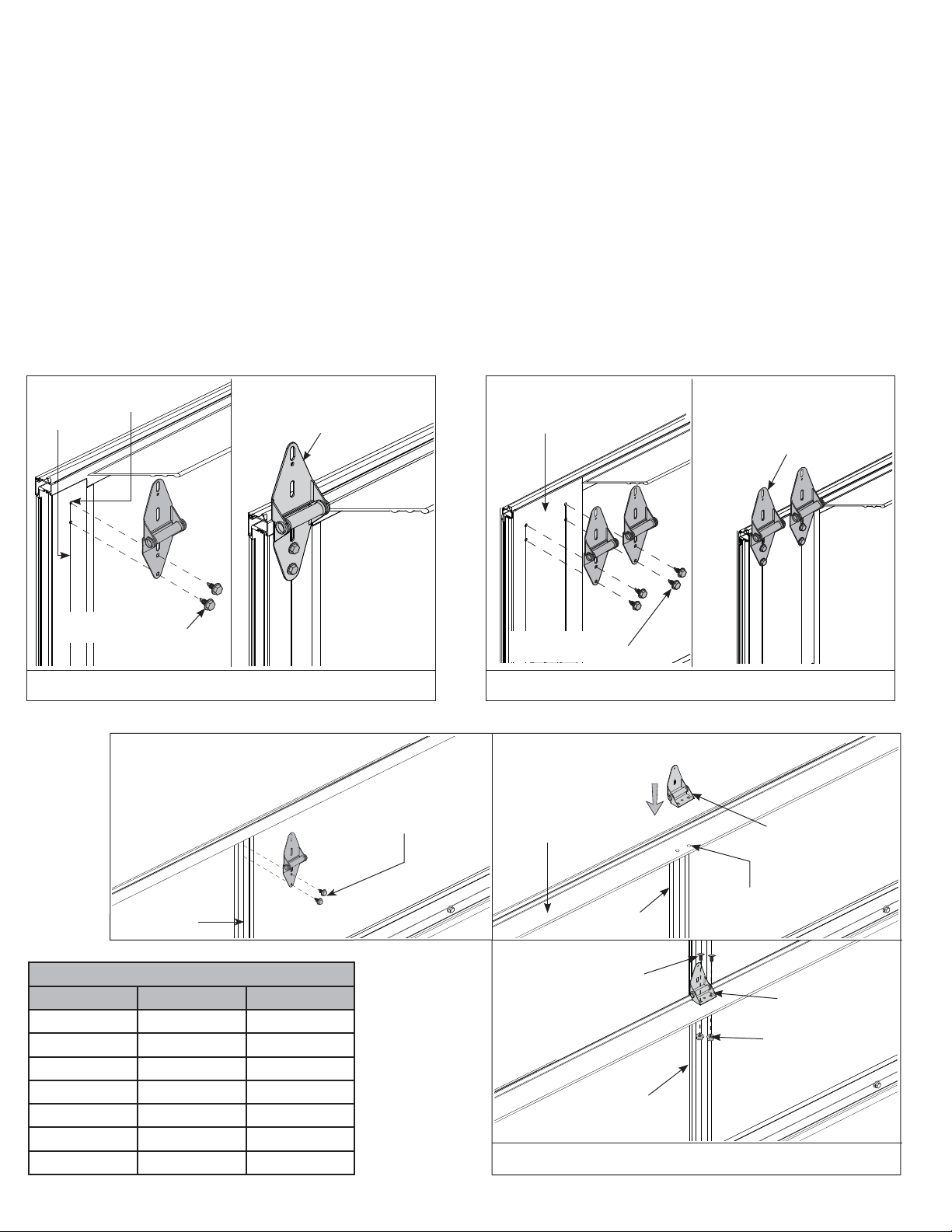
BOTTOM SECTION/ VERTICAL TRACK
Center and level (or support to a known grade level) the bottom section in the opening, using shims if necessary, as seen in FIG H. Temporarily attach the wall angles to the jambs with
the appropriate lag screws, as shown in FIG H-1, FIG H-2 and FIG H-3. Allow 1/2” clearance between the section and the vertical tracks as illustrated in the sidereoom requirements
illustrations on page 3. It is important that the top of each track is on the same plane.
NOTE: Products being installed to precast or block must use a 3/8” x 3” sleeve anchor to attach the wall angle to the building, as shown in FIG H-3. Use the slots in the wall angle as a drill
template and drill a 3/8” hole (3-1/2” deep) and secure to anchor.
Stack the bottom section into position by hooking the left hand roller into the left hand vertical track, as shown in FIG H-4. Insert a roller into the proper, uninstalled right hand end hinge,
and place the roller into the right hand vertical track. Lower the roller and hinge into the proper position over the section, and attach to the section in the same manner the left hand end
hinge was attached, as described on page 5.
WALL ANGLE
5/16” X 1 5/8” LAG
FIG H-2
SCREW FOR USE ON
WOOD JAMBS.
FIG H-1
FIG H-3
5/16” X 1” SELF
WALL ANGLE
13”
DRILLING &
TAPPING SCREW
FOR USE ON STEEL
JAMBS.
30” OR
18”
24”
O.C.
MAX
24”
O.C.
MAX
24”
10”
NOTE: TYPICAL FASTENER SPACING.
FIG H-1
VERTICAL TRACK
FIG H-4
FIG H-2
3/8” X 3” SLEEVE
ANCHOR (BY
OTHERS) FOR USE
ON PRE-CAST
CONCRETE.
( DRILL A
3/8” X 3-1/2” DEEP
HOLE)
FIG H-3
STACK THE SECTION
INTO POSITION, BY
HOOKING THE LEFT
HAND ROLLER INTO
THE VERTICAL TRACK
AND REPEATING FOR
THE RIGHT HAND SIDE.
FIG H-4
FIG H
STACKING SECTIONS
Locate the Lock Section (the second section) and insert a roller into the left end hinge. Stack this section into the opening by hooking the roller into the left hand vertical track and lowering
the section onto the bottom section, as shown in FIG I. Insert a roller into the proper, uninstalled right hand end hinge, and place the roller into the right hand vertical track. Lower the roller
and hinge into the proper position over the section, and attach to the section in the same manner the left hand end hinge was attached, as described on page 5. Verify section alignment,
and fl ip up the upper hinge leaf(s) from the bottom section and secure to the lock section using 1/4”-20 x 7/8” self-drilling screws. Continue to stack the remaining sections in the proper
sequence, except for the top section.
6
Page 7

HOOK LEFT HAND
ROLLER INTO TRACK
LOCK SECTION
SLIDE RIGHT ENDHINGE AND
ROLLER DOWN VERTICAL TRACK
AND OVER LOCK SECTION
FIG I
TOP BRACKETS/ TOP SECTION
Align upper-center hole of top bracket with vertical groove on the end stile and ensure top bracket is level and aligned with edge of top section. Secure with (4) 1/4”- 20 x 7/8” self drilling
screws, one in each corner of the top bracket, as shown in FIG J. Loosely fasten top bracket slide with (1) 5/16” x 3/4” carriage bolt and fl ange hex nut. Insert roller into slide. Repeat for other
side. If your door has double end stiles then it will require 2 top brackets; as shown in FIG K, in which case an additional top bracket will be installed in the same manner next to the fi rst top
bracket with one roller being placed through both top bracket slides. 2 reinforcement brackets will then be installed under the 2 top brackets and secured to the section with (2) 1/4”- 20 X
7/8” self drilling screws.
If your door is trolley operated; it is recommended that an optional strut be installed on the top rail.
Now stack the top section, take care to ensure it is aligned properly with the other sections.
TOP BRACKET
BASE
END STILE
TOP SECTION
(4) 1/4”- 20 X 7/8” SELF
DRILLING SCREWS
FIG J
TOP SECTION
(8) 1/4”- 20 X 7/8” SELF
DRILLING SCREWS
FLANGE HEX NUT
(2) REINFORCEMENT
BRACKETS
(1) 5/16” X 3/4”
CARRIAGE BOLT
TOP
BRACKET
SLIDE
TOP
BRACKET
BASE
(2) 1/4”- 20 X 7/8” SELF
DRILLING SCREWS
TOP SECTION
FIG K
7
Page 8

VERTICAL TRACK ADJUSTMENT
Adjust the spacing of the vertical tracks from 3/8”-5/8” spacing at the bottom section to 3/4”-7/8” spacing at the top section; refer to page 3. Permanently secure each vertical track to the
jambs.
HORIZONTAL TRACKS/ ADJUSTING TOP BRACKET
Use chain or cable to temporarily suspend the rear of the horizontal track assembly. Align the curved end of the horizontal track assembly with the top of the vertical track. Secure the
horizontal track to the splice plate or fl agangle using (2) 1/4” x 9/16” track bolts and hex fl ange nuts as shown in FIG L-4. Secure the horizontal reinforcing angle to the wall angle using (1)
3/8” x 3/4” truss bolt and nut as shown in FIG L-3; ignore the counterbalance hardware in this illustration; this hardware will be installed in the next step.
With tracks installed you can adjust the top brackets. Starting on one side, slide the top bracket roller(s) out against the horizontal track. Maintaining the slide’s position, tighten the
5/16” x 3/4” carriage bolt(s) and fl ange hex nut(s) to secure the top bracket slide(s) to the top bracket base. Repeat for other side.
COUNTERBALANCE
WARNING
INSTALL SUPPORT BRACKETS TO SOLID STRUCTURAL MEMBERS ONLY. DO NOT INSTALL OVER DRY WALL OR PANELING. FAILURE TO INSTALL SUPPORT BRACKETS TO SOLID
STRUCTURAL MEMBERS CAN CAUSE SEVERE OR FATAL INJURY.
WARNING
FAILURE TO USE PROPER NUMBER OF FASTENERS CAN RESULT IN SUDDEN SPRING TENSION RELEASE, CAUSING SEVERE OR FATAL INJURY.
NOTE: Spring pads must be securely anchored before proceeding, as shown in FIG M-2. The pads must by fl ush with the jambs.
Attach the EBF’s (end bearing brackets) to the horizontal reinforcing angles using (2) 3/8” x 3/4” truss bolts and nuts, as shown in FIG L1, L2, L3.
Attach the EBF’s to the jambs using (2) 5/16” x 1-5/8” lags (wood), (2) 5/16” x 1” self-drilling and tapping screws (steel), or (2) 3/8” x 3” sleeve anchors (precast) (anchors by others).
Install the Center Support Bracket(s) to the spring pads at the same elevation as the bearing in the EBF’s. Depending on the construction different fasteners must be used.
Steel: Secure each center support bracket using (3) 5/16” x 1” self-drilling and tapping screws as detailed in FIG M-3.
Pre-Cast: Secure each center support bracket using (2) 1/2” x 3” sleeve anchors (by others). This installation will require the 1/2” anchors to be secured to the building, then securing the
brackets to the anchors as detailed in FIG M-4.
Block Construction: Attach perforated angle 18” long to center support bracket(s) using (2) 3/8” x 1-1/4” bolts and nuts. Chamfer angle to clear top section high arc. Secure center
support bracket(s) and perforated angle to block using (4) 3/8” x 2-1/2” sleeve anchors as detailed in FIG M-1.
For 6” Springs: Attach DSB wall angle(s) to the spring pads. Fasten the spring plate to the wall angle bracket, as shown in FIG P.
NOTE: 1” GRADE 5 bolts are provided and must be used with the fl at and locking washers, to fasten the spring plate to the DSB wall angle.
NOTE: Additional center support brackets are not required for coupler support.
Torsion spring assemblies:
Torsion spring assemblies can be of several confi gurations depending on door size and weight. Left or right hand spring(s) must be identifi ed by the color of the winding cone (Refer to
FIG N, O and P. Ensure that spring warning tags are securely wired to all stationary spring cones.
NOTE: All red winding cone springs will be on the left side and all black winding cone springs will be on the right side.
NOTE: All set screws on drums and winding cones are painted red.
Locate torsion shaft and lay it in front of door on garage fl oor. Assemble torsion shaft assembly components according to spring and torsion shaft type as shown in FIG N, O, and P.
For 2” or 2-5/8” Spring(s) (Tubular Shaft Only): Install the loose steel bearing onto shaft (1 per spring(s)) and insert into stationary cone.
For 2-5/8”, solid shaft with coupler, 1 spring per bracket or 3-3/4” springs: Install the loose steel bearing onto shaft (1 per spring) and insert into the stationary cone. NOTE: Additional
center support brackets are not required for coupler support.
Lift the torsion shaft assembly into place by placing one end of the shaft into the end bearing bracket followed by the other end. Make sure the torsion shaft assembly and it’s components
are positioned properly with respect to the end and center support brackets, as shown in FIG N, O and P. The torsion shaft should be level and held in place by the end and center support
bracket(s). Secure the spring stationary cone(s) (dead end) to the center support bracket(s) using 3/8” bolts and nuts. Keep spring warning tags clearly visible.
NOTE: The center support brackets require (2) fasteners in the lower slot and hole, then (1) fastener in the top slot.
NOTE: Each 3-3/4”, 6” and Duplex spring is secured to a separate center support bracket. DO NOT attach two springs of this size to one center support bracket.
8
Page 9

FIG L-1, L-2 & L-3
FIG. L-4
EBF
EBF
THIS ILLUSTRATION
SHOWS 15” RADIUS
TRACK W/CONCRETE
ANCHOR
FIG. L-1
THIS ILLUSTRATION SHOWS
12” RADIUS TRACK W/LAG
BOLT TO WOOD.
EBF
CUT OFF 3” OF WALL
ANGLE , 12” RADIUS
APPLICATIONS ONLY
FIG. L-2
THIS ILLUSTRATION SHOWS
15” RADIUS TRACK W/SELF
DRILLING SCREW TO STEEL
(3) 3/8” X 3/4” TRUSS
BOLTS AND NUTS.
(2) FOR SECURING
END BRACKET
(1) FOR SECURING
HORIZONTAL ANGLE
TO FLAG ANGLE
FIG. L-3
1/4” X 9/16” TRACK
BOLTS AND NUTS
CENTER SUPPORT BRACKET
SLEEVE ANCHOR
POSITIONED IN
BOTTOM SLOT OF
SUPPORT BRACKET
PERFORATED ANGLE
(TRIMMED TO CLEAR
DOOR HIGH-ARC)
(4) 3/8” x 2-1/2” SLEEVE ANCHOR
NOTE: ALL ANCHORS MUST BE
POSITIONED A MINIMUM OF 1” FROM
BLOCK EDGE.
FIG M-1
FIG L
(2) 3/8” X 1-1/4” HEX
HEAD BOLTS AND NUTS
SECOND ANCHOR
FROM BOTTOM
MUST BE BELOW
SUPPORT BRACKET
SPRING MOUNTING PAD. 2 X 6 WHITE
PINE OR DENSER. SECURED WITH MIN.
(4) 5/16” X 4” LAG BOLTS INTO HEADER.
TOP PLATE
HEADER
(2) 3/8” X 1-1/2”
BOLTS
FIG M-2
FIG. L-4
(2) 3/8” NUTS
AND WASHERS
5/16” X 1-5/8”
LAG SCREWS
PERIMETER
SEAL
9
Page 10

STEEL
(2) 1/2” X 3”
(3) 5/16” X 1” SELF-DRILLING
AND TAPPING SCREWS
SLEEVE ANCHOR
NOTE: MUST SECURE
SLEEVE ANCHORS TO
BUILDING FIRST , THEN
ATTACH BRACKETS TO
ANCHORS.
FIG M-3 FIG M-4
ONE or TWO SPRINGS (2” or 2-5/8” ONLY)
3” MINIMUM SPRING PAD WIDTH
(6” IF FOR TROLLEY OPERATOR)
PRE-CAST
RIGHT HAND DRUM
BLACK
LEFT HAND DRUM
RED
LEFT HAND DRUM
RED
WINDING CONE
RED
CENTER SUPPORT BRACKET
TWO SPRINGS (3-3/4”) TUBULAR OR 1 PIECE SOLID SHAFT
3-1/2”
WINDING CONE
RED
WINDING CONE
BLACK
RIGHT HAND DRUM
BLACK
WINDING CONE
BLACK
10
9” MINIMUM SPRING PAD WIDTH
NOTE: 6” SPRINGS UTILIZE SOLID SHAFTS
FIG N
Page 11

TWO OR MORE SPRINGS (2-5/8” or 3-3/4”) SPLIT SOLID SHAFT
17” MINIMUM
SPRING PAD WIDTH
13”
RIGHT HAND DRUM
BLACK
3” MINIMUM SPRING PAD WIDTH
LEFT HAND DRUM
RED
TWO OR MORE SPRINGS (6”) SPLIT SOLID SHAFT
WINDING CONE
BLACK
COUPLING
WINDING CONE
RED
FIG O
RIGHT HAND DRUM
BLACK
17” MINIMUM SPRING
PAD WIDTH
IF PROVIDED
LEFT HAND DRUM
3” MINIMUM SPRING
PAD WIDTH
RED
WINDING CONE
RED
13”
WINDING CONE
BLACK
COUPLING
(2) 3/8” X 1” GRADE 5 BOLT
AND NUT WITH (2) FLAT
WASHERS EACH AND (1)
LOCK WASHER EACH PER
DSB WALL ANGLE AND
SPRING PLATE
SPRING PLATE
DSB WALL ANGLE
FIG P
11
Page 12

WINDING SPRINGS
WARNING
APPLY LOCKING PLIERS TO THE TRACKS ABOVE THE THIRD ROLLER, OR LOCK DOOR IF APPLICABLE, BEFORE WINDING THE SPRING(S) TO PREVENT DOOR FROM
RISING UNEXPECTEDLY, POSSIBLY RESULTING IN SEVERE OR FATAL INJU RY.
WARNING
WINDING BARS MUST FIT SNUGGLY INTO HOLES IN SPRING WINDING CONES. ATTEMPTING TO WIND SPRINGS WITH LOOSELY FITTING RODS, SCREWDRIVERS OR
OTHER IMPROPER TOOLS CAN RESULT IN SEVERE OR FATAL INJURY.
Feed the cable attached to the left hand bottom bracket up the vertical track, behind the rollers and secure to the left hand drum. Push the drum up against the end
bearing bracket and secure to the shaft by tightening the set screws (solid shafts use 1/4” key(s) and set screws to secure drums).
Rotate drum and shaft until cable is taut, then apply locking pliers to torsion shaft with end resting against header. This will hold cable taut and on drum. There must be
at least 1/2 wrap of cable on the drum. If not, contact Wayne-Dalton for proper length cables. Attach other cable to right hand drum. Push drum against end bearing
bracket and rotate drum until cable is taut. Secure drum to shaft by tightening the set screws. Cable tension must be equal on both drums on single shaft applications.
On split shaft applications, apply locking pliers to both torsion shafts, and secure bolts in coupling after springs are fully wound.
Carefully, following spring winding instructions detailed in FIG Q, wind spring(s), using the appropriate 1/2”, 5/8” or 3/4” diameter winding rods of suffi cient length; wind
spring 1/4 turn at a time to the number of complete revolutions recommended on the spring turn chart. When the proper number of turns is reached, tighten the set
screws on the winding cone. Release the locking pliers from the spring shaft(s). Adjust the coupler on split solid shafts until drums are in line (check door level) and
tighten coupler.
NOTE: Coupling used on solid shaft only. Tighten connecting bolts after winding springs.
SPRING TURN CHART
DOOR HEIGHT 400-8 400-12 5250-18 800-32
6’6” 7.5 7.5
7’0” 7.875 7.875
7’6” 8.5 8.5
8’0” 8.875 8.875 6.75
8’6” 9.25 7.125
9’0” 9.5 7.375
9’6” 10.125 7.75
10’0” 10.5 8.125 5.375
10’6” 11 8.375 5.625
11’0” 11.5 8.875 5.875
11’6” 12 9.125 6
12’0” 12.5 9.5 6.25
12’6” 9.875 6.5
13’0” 10.25 6.75
13’6” 10.5 7
14’0” 10.875 7.375
14’6” 11.25 7.5
15’0” 11.5 7.625
15’6” 11.875 8
16’0” 12.25 8.125
16’6” 12.5 8.25
WIND SPRINGS
TOWARD CEILING.
(STANDARD LIFT
APPLICATIONS)
FIG Q
12
Page 13

REAR SUPPORTS
After spring(s) are wound, cautiously remove locking pliers from vertical tracks, while pushing downward on door to prevent it from raising unexpectedly, in case spring(s)
were over wound. Carefully and slowly raise door, until one and a half sections are in the horizontal tracks. Lock door in this position using locking pliers attached to
vertical tracks above bottom roller on one side and below bottom roller on other side of door.
Space the horizontal tracks 3/4”-7/8” from section edge and level. Using 1-5/8” x 2-3/8” x 12 Ga. angle, fabricate back hangers and attach them to building as shown in
FIG R using 3/8” bolts and nuts. Laterally brace all drop angles once proper spacing is achieved.
Doors over 11 ft. high and over 14 ft. wide must have (1) intermediate drop hanger as shown in FIG R.
Doors over 16’ high must have (2) intermediate drop hangers as shown in FIG R.
INTERMEDIATE HANGERS FOR ALL DOORS OVER
11’ HIGH AND OVER 14’ WIDE. POSITIONED HALF
WAY BETWEEN JAMB AND BACK HANGER.
LATERAL BRACE ALL
HANGER ANGLES.
DOORS OVER 16’ HIGH USE 2
INTERMEDIATE HANGERS.
USE 12 GA. MINIMUM ANGLE
(1-5/8” X 2-3/8”)
APPLY LOCKING PLIERS TO VERTICAL TRACK ABOVE
AND BELOW BOTTOM ROLLERS, ON EACH SIDE , TO
SECURE WHILE ATTACHING BACK HANGERS.
INTERMEDIATE HANGERS. BACK HANGERS.
3/4”-7/8”
USE A 3/8” X 3/4”
TRUSS BOLT FOR
ROLLER CLEARANCE.
3/8” DIA. BOLT SHOULD
PROTRUDE INTO TRACK TO
SERVE AS A ROLLER STOP.
FIG R
13
Page 14

SPRING ADJUSTMENTS
Release the locking pliers from vertical tracks and check the door’s counterbalance. Adjust springs if necessary. If door does not balance properly, verify that all supplied
components such as struts are installed. Verify quantity, wire diameter, spring size & drums to the spring tag. Check Cable length. Add or subtract up to one turn on the
springs. Contact Wayne-Dalton Corp. if problem persists.
FINAL ADJUSTMENTS
Vertical tracks can now receive fi nal adjustments. Open and close the door a few times, checking and adjusting side clearance (if necessary). Tighten jamb fasteners (lags,
self drilling, or anchors) to permanently secure verticals. Adjust door in or out from jamb by loosening the track to obtain proper seal. Permanently tighten all track bolts.
Lubricate springs, rollers, and bearing with oil. DO NOT GREASE THE INSIDE OF THE TRACK.
ALTERNATE STEEL SPRING PAD APPLICATIONS
Contact Manufacturer For Applications Not Covered Below
Maximum Door Size 9’ x 9’ (Maximum Door Weight 210 lb.)
Cut perforated angle (1-5/8 x 2-3/8” x 11 GA.) to Dim “Y”. Thru-bolt top and bottom of angle to each girt using (4) 3/8” x 1-1/4” bolts and nuts. Thru-bolt center bracket
to perforated angle using (2) 3/8 x 1-1/4” bolts and nuts (See FIG S).
Maximum Door Size 14’ x 12’ (Maximum Door Weight 400 lb.)
Cut (2) perforated angle (1-5/8 x 2-3/8” x 11 GA.) to Dim “Y”. Thru-bolt top and bottom of each angle to each girt using (4) 3/8” x 1-1/4” bolts and nuts. Thru-bolt each
center bracket to perforated angle using (2) 3/8 x 1-1/4” bolts and nuts (See FIG T).
Maximum Door Size 14’-2” x 12’-1” (Maximum Door Weight 800 lb.)
Cut (2) pieces of perforated angle (1-5/8 x 2-3/8” x 11 GA.) to Dim “Y” and (2) more pieces at Dim “Y” minus 3. Bolt the angles together into a “Z” shape using (4) 3/8” x
1-1/4” bolts and nuts. Thru-bolt top and bottom of each “Z” shaped angle to each girt using (4) 3/8” x 1-1/4” bolts and nuts. Thru-bolt each center bracket to perforated
angle assembly using (2) 3/8 x 1-1/4” bolts and nuts (See FIG U).
NOTE: Do NOT Bolt (2) 3-3/4” Torsion Springs To ONE Center Bracket
NOTE: These spring mounting techniques are not supported for 800-32, 6375-164, 1100-18, 1350-28, & 800-120 drums. These instructions are also not
applicable for 5750-120 drums with 72” Or more high-lift
NOTE: Maximum spacing for dimension “Y” is 84 in. (7 ft.) These instructions are not applicable for a span greater than 84 in.
GIRT
HEAVY PERFORATED ANGLE
(1-5/8 X 2-3/8” X 11 GA.)
CENTER SPRING BRACKET
(2) 3/8” X 1-1/4” BOLTS TO
SECURE BRACKET TO ANGLE
“Y”
(< 7 FT.)
(2) 3/8” X 1-1/4” BOLTS
& NUTS TOP & BOTTOM
GIRT
14
FIG S
Page 15

“Y”
(< 7 FT.)
GIRT
GIRT
SPACE CENTER
BRACKETS 12” - 14”
APART ON APPLICATIONS
REQUIRING COUPLERS
HEAVY PERFORATED ANGLE
(1-5/8 X 2-3/8” X 11 GA.)
CENTER SPRING
BRACKET
(2) 3/8” X 1-1/4”
BOLTS TO SECURE
BRACKET TO ANGLE
(2) 3/8” X 1-1/4” BOLTS &
NUTS TOP & BOTTOM
GIRT
“Y”
(< 7 FT.)
(2) 3/8” X 1-1/4” BOLTS &
GIRT
NUTS TOP & BOTTOM
SPACE CENTER
BRACKETS 12” - 14”
APART ON APPLICATIONS
REQUIRING COUPLERS
HEAVY PERFORATED ANGLE
(1-5/8 X 2-3/8” X 11 GA.)
CENTER SPRING
BRACKET
BOLT “Z” SHAPED
ASSEMBLY USING (4)
3/8” X 1-1/4” BOLTS
AND NUTS
(2) 3/8” X 1-1/4”
BOLTS TO SECURE
BRACKET TO ANGLE
FIG T
FIG U
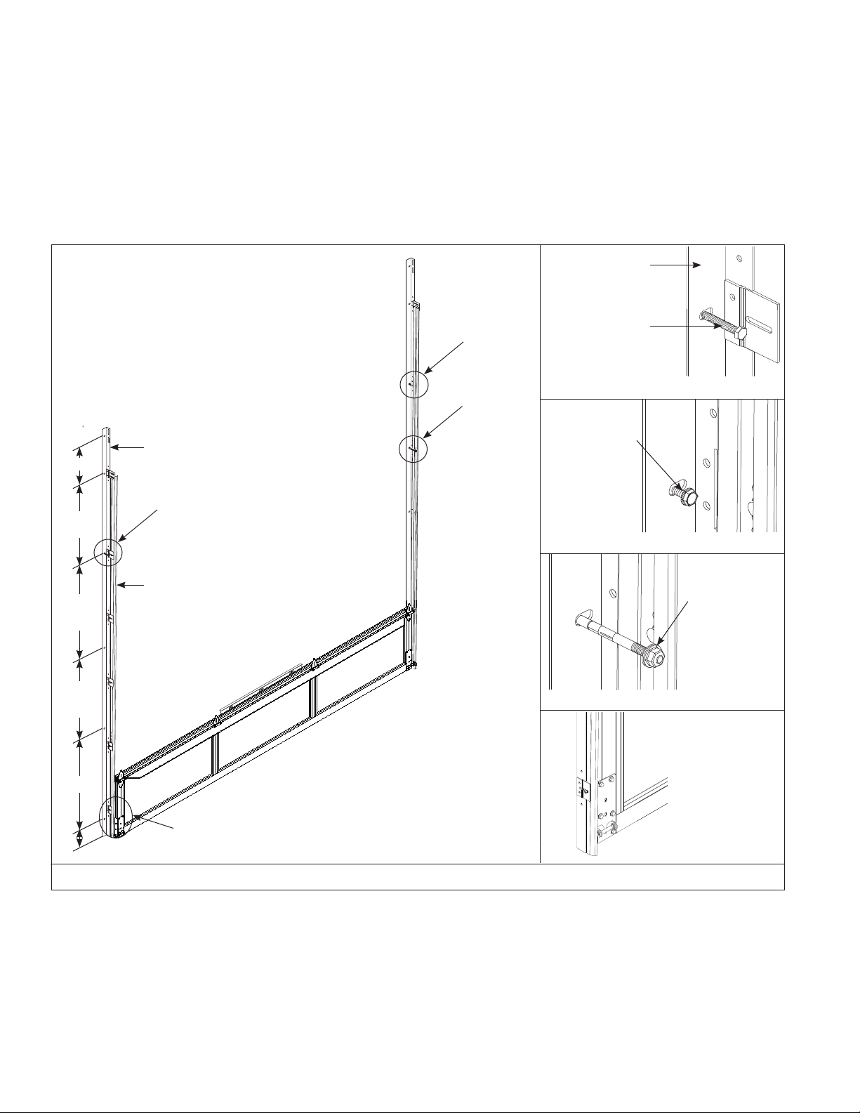
INSIDE SIDE LOCK INSTALLATION
Install lock on second section of door.
Secure the lock to the section with (4) 1/4”- 20 X 5/8” self drilling screws, as shown in FIG V.
The side lock should be spaced approximately 1/8” from the section edge. Ensure that lock is square with section and lock bolt aligns with lock hole in vertical track.
VERTICAL TRACK
ALIGN WITH SLOT IN TRACK
(4) 1/4”-20 X 5/8: SELF-DRILLING
SELF DRILLING SCREWS
SIDE LOCK
FIG V16FIG X
15
Page 16

STEP PLATE INSTALLATION
Position your step plate, on the inside of the door, over the bottom section end stile on the side of the door containing the side lock. Secure step plate to endstile with
(2) 1/4”-20 x 7/8” Self-drilling screws, as shown in FIG W. For doors ordered with non-keyed locks, a second step plate is provided. Install the second step plate in the
same manner as the fi rst, on the lock section (second section), below the side lock.
IF SECOND STEP PLATE WAS
RECEIVED FOR DOORS ORDERED
WITH NON-KEYED LOCKS, INSTALL
IT BELOW THE SIDE LOCK.
LOCK SECTION
END STILE
STEP PLATE
BOTTOM SECTION
(2) 1/4”-20 X 7/8” SELF-
DRILLING SCREWS
FIG W
EXHAUST PORT INSTALLATION
Install the exhaust port using (3) #10 x 1-1/2” counter sunk bolts and nuts, as shown in FIG X.
Exhaust port goes on the inside of bottom section and can be installed into the aluminum panel or a double wide bottom rail.
OUTSIDE TRIM RING
ALUMINUM PANEL
(3) #10 HEX NUTS
EXHAUST PORT
GASKET
GASKET
(3) #10 X 1-1/2”
COUNTER SUNK BOLT
DOUBLE WIDE
BOTTOM RAIL
Page 17

CABLE KEEPER INSTALLATION
Place cable keeper between roller carrier tabs. Insert roller through holes in the tabs and through cable keeper. Rotate arm up and hook around cable, letting cable
keeper arm pull against the counterbalance cable, keeping it taut, as shown in FIG Y.
NOTE: Cable keepers are color coded, black for right hand and red for left hand.
IMPORTANT: Cable keepers are intended to keep cables from coming off drums on manually operated doors.
CABLE
KEEPER
CABLE
ROLLER
CABLE
KEEPER
FIG Y
CHAIN HOIST INSTALLATION (STANDARD LIFT APPLICATIONS)
Chain Hoists and JackShaft Operators are limited to:
1.) Standard Lift Doors with roof pitch track 2:12 or greater.
2.) High Lift track greater than or equal to 24”.
3.) High Lift track 12” thru 24” with roof pitch track 1:12.
If your door is to be trolley operated, it is recommended that an optional strut be installed on the top section.
Wayne-Dalton recommends the use of a trolley rail(s) and auxiliary shaft for standard or high lift doors below these limits. Cable Keepers are recommended for all chain
hoist or jackshafts operators. Install the chain hoist or sprocket as close to the end bearing bracket as possible, to minimize torsion shaft defl ection, as shown in FIG Z.
Chain tensioners are recommended for door over 144 sq. ft. with jackshaft operators.
Wayne-Dalton recommends the use of a trolley rail(s) coupled to an auxiliary shaft that is powered by a side mount type chain hoist as shown in FIG Z.
9’” of extra headroom are required for these installations.
Assemble the trolley rail as per the manufactures installation instructions. Secure the trolley header bracket to the building using the appropriate fasteners
(2-5/16” X 1-5/8” lags for wood, 2-5/16” X 1” self drilling and tapping screws for steel, and 2-3/8” 2-1/2” sleeve anchors for masonry.
Back hang the trolley using angles, center hang supports are required for doors over 14’ wide and 12’ high.
Attach the trolley arm to the bracket.
Secure the auxiliary shaft to the building with bearing brackets and couple the shaft to the trolley rail.
Assemble the chain hoist and secure to the auxiliary shaft.
17
Page 18

1/2” X 3” MIN. SLEEVE
ANCHOR (BY OTHERS),
5/16” X 1” SELF-DRILLING
AND TAPPING SCREW OR
5/16” X 1-5/8” LAG BOLT
COUPLING
5” MIN. EXTRA HEADROOM REQUIRED
1/2” X 3” MIN. SLEEVE
ANCHOR (BY OTHERS),
5/16” X 1” SELF DRILLING
AND TAPPING SCREW OR
5/16” X 1-5/8” LAG BOLT
NOTE: Install Sprocket or chain
hoist as close to track as possible,
minimum of 3/4”, to minimize shaft
defl ection.
TOP SECTION
PUSHER SPRING
SINGLE TROLLEY OPERATOR BRACKET IS DOOR SIZE DEPENDENT.
TROLLEY OPERATOR BRACKET IS SUPPLIED BY OTHERS
(2) 3/8” DIAMETER
HOLES
(2) 3/8” X 1-1/4”
HEX HEAD BOLTS
AND NUTS
Pusher Spring Installation:
Raise door until bottom section is 3/4” below header. Align pusher spring with the top corner of the top section. (Compress against the top bracket fl ange.)
Drill (2) 3/8” holes in each track and secure using (2) 3/8” x 1-1/4” hex head bolts and nuts. (bolt may extend into track.)
FIG Z
18
Page 19

Broken Cable Safety Device Installation
1. Attach the broken cable safety device, with cable attached, to the section using (8) 1/4”-20 X 5/8” self drilling screws.
2. Place the bottom section in the opening.
3. Install the verticals over the rollers.
4. Follow the rest of the door installation per the instruction manual.
5. After the door installation is complete, rotate the cam arm up, and connect the cable arm to the cam arm with the bolt and locking nut.
6. Operate the door to verify that there is clearance between the track and section for the cable arm.
7. Adjust the track as needed.
CABLE ARM
CABLE ARM
BROKEN CABLE
SAFETY DEVICE
(SES)
CAM ARM
#10 X 1-1/2”
BOLT W/LOCK NUT
5/8” X 20 SELF
DRILLING SCREWS (8)
MAINTENANCE AND FINISHING INSTRUCTIONS
MAINTENANCE
An occasional light cleaning will also help maintain an aesthetically pleasing appearance. The only regular maintenance necessary is that of annual washing. Mild solutions of
detergents or household ammonia will aid in the removal of most dirt, and the following are recommended levels:
One cup of Tide™, or other common detergents, which contain less than 0.5% phosphate, dissolved into fi ve gallons of warm water. NOTE: The use of detergents containing greater
than 0.5% phosphate is not recommended for use in general cleaning of garage doors. NEVER BLEND CLEANSERS OR DETERGENTS WITH BLEACH.
ACRYLIC GLAZING CLEANING INSTRUCTIONS:
1. To clean acrylic glazing wash with plenty of nonabrasive soap or detergent and water. Use the bare hand to feel and dislodge
any caked dirt or mud. A soft, grit-free cloth, sponge or chamois may be used to wipe the surface. Do not use hard or rough
cloth that will scratch the acrylic glazing. Dry with a clean damp chamois.
2. Grease and oil may be removed with kerosene or a good grade of naphtha (No aromatic content.). Users of these solvents
should become familiar with their proper ties to handle them safely.
3. Do not use: Window cleaning fl uids, scouring compounds, gritty cloths, leaded or ethyl gasoline, or solvents such as alcohol,
acetone, carbon tetrachloride, etc.
19
Page 20

door for FIVE (5) YEARS
Subject to the terms and conditions contained in this Limited Warranty, Wayne-Dalton Corp. (“Manufacturer”) warrants the sections of the
installation against:
(i) Fading, cracking or chipping of the anodized or powder coated finish.
(ii) Fogging or condensation forming inside of the insulated glass unit.
(iii) Chipping, cracking, scratching, breaking, or discoloration of the glass due to defects in material or workmanship.
Limited Warranty
Model 451, 452 & K-AL
with the exception of the following items. These items will be warranted for a period of ONE (1) YEAR from the date of
the manufacture.
YEARS from the date of installation, against defects in material and workmanship, subject to all the terms and conditions below.
in material and workmanship for a period of ONE (1) YEAR
transferable, nor does it extend benefits to any other buyer (even when the property is sold). As a result this Limited Warranty does NOT apply to any
person who purchases the product from someone other than an authorized Wayne-Dalton dealer or distributor.
its components, abuse, damage from corrosive fumes or substances, salt spray or saltwater air, fire, Acts of God, failure to properly maintain the door, or
attempt to use the door, its components or related products for other than its intended purpose and its customary usage. This Limited Warranty does not
cover ordinary wear. This Limited Warranty will be voided if any holes are drilled into the door, other than those specified by the Manufacturer.
WARRANTIES, EXPRESS OR IMPLIED (INCLUDING BUT NOT LIMITED TO THE WARRANTY OF MERCHANTABILITY OR FITNESS FOR
A PARTICULAR PURPOSE) WILL EXTEND BEYOND THE TIME PERIOD SET FORTH IN UNDERSCORED BOLD FACE TYPE
LIMITED WARRANTY, ABOVE.
was purchased. Unless the dealer is no longer in business, a written claim to the Manufacturer will be the same as if no claim had been made at all.
the product on site, or Buyer may be required to return the product to the Manufacturer at Buyer’s expense. Buyer agrees to cooperate with any
representative of the Manufacturer and to give such representative full access to the product with the claimed defect and full access to the location of its
installation.
product to be repaired or replaced. The decision about the manner in which the defect will be remedied will be at the discretion of the Manufacturer,
subject to applicable law. THE REMEDY WILL COVER ONLY MATERIAL. THIS LIMITED WARRANTY DOES NOT COVER OTHER
CHARGES, SUCH AS FIELD SERVICE LABOR FOR REMOVAL, INSTALLATION, PAINTING, SHIPPING, ETC.
this Limited Warranty; provided, however, that the installation date for the repaired or replaced product will be deemed to be the date the original product
was installed, and this Limited Warranty will expire at the same time as if there had been no defect. If a claim under this Limited Warranty is resolved in a
manner other than described in the immediately preceding paragraph, then neither this Limited Warranty nor any other warranty from the Manufacturer
will cover the repaired or replaced portion of the product.
remedy. The liability of the Manufacturer, whether in contract or tort, under warranty, product liability, or otherwise, will not go beyond the
Manufacturer’s obligation to repair or replace, at its option, as described above. THE MANUFACTURER WILL NOT UNDER ANY
CIRCUMSTANCES BE LIABLE FOR SPECIAL, INCIDENTAL, OR CONSEQUENTIAL DAMAGES, including (but not limited to) damage or loss of
other property or equipment, personal injury, loss of profits or revenues, business or service interruptions, cost of capital , cost of purchase or replacement
of other goods, or claims of third parties for any of the foregoing.
Warranty or to grant any other warranty on behalf of or binding on the Manufacturer, and anyone’s attempt to do so will be null and void.
to the extent permitted by law.
The Manufacture will not be responsible for glass chipping, breaking, or cracking resulting from any circumstances beyond the direct control of
The Manufacturer warrants the garage door hardware (except springs) and the tracks of the above-described door, for a period of FIVE (5)
The Manufacturer warrants those component parts of the door not covered by the preceding provisions of this Limited Warranty against defects
from the date of installation.
This Limited Warranty is extended only to the original purchaser – property owner (where the door is installed).This Limited Warranty is not
The Manufacturer will not be responsible for any damage attributable to improper storage, improper installation, or any alteration of the door or
THIS LIMITED WARRANTY COVERS A CONSUMER PRODUCT AS DEFINED BY THE MAGNUSON-MOSS ACT. NO
IN THIS
x Some States do not allow limitations on how long an implied warranty lasts, so the above limitations may
not apply to you.
Any claim under this Limited Warranty must be made in writing, within the applicable warranty period, to the dealer from which the product
At the Manufacturer’s option, pursuant to the dealer having notified the Manufacturer of a warranty claim, a service representative may inspect
If the Manufacturer determines that the claim is valid under the terms of this Limited Warranty, the Manufacturer will cause the defective
Any repairs or replacements arranged by Manufacturer will be covered by (and subject to) the terms, conditions, limitations and exceptions of
THE REMEDIES FOR THE BUYER DESCRIBED IN THIS LIMITED WARRANTY ARE EXCLUSIVE and take the place of any other
x Some States do not allow the exclusion or limitation of incidental or consequential damages, so the above
limitation or exclusion may not apply to you.
No employee, distributor, dealer, representative, or other person has the authority to modify any term or condition contained in this Limited
Buyer should be prepared to verify the date of installation to the satisfaction of the Manufacturer.
The rights and obligations of the Manufacturer and Buyer under this Limited Warranty will be governed by the laws of the State of Ohio, USA,
x This Limited Warranty gives you specific legal rights and you may also have other rights, which may vary
from State to State.
20
 Loading...