


W I R E L E S S C O M M U N I C A T I O N S Y S T E M S
SPS-5 v9E Paging System Manual
Version 9.XXE Firmware
Copyright WaveWare Technologies, Inc. 2014 - All Rights Reserved
SPS-5 v9E
Ethernet and Serial Port Paging System
WaveWare Technologies, Inc. 2630 National Dr. Garland, TX. 75041
Phone: 1.800.373.1466 Fax: 972.479.1735
www.WirelessMessaging.com
Table of Contents
Introduction |
Page |
3 |
Warranty and other Misc Information |
Page |
8 |
Obtaining Pagers for your Paging System |
Page |
9 |
Paging System Operation |
Page |
10 |
Paging System Installation |
Page |
11 |
Quick Start Guide |
Page |
12 |
Encoder Setup Software Programming Guide |
Page |
13 |
Web Browser Programming Guide |
Page |
30 |
Appendix “A” – TAP Interface Specifications |
Page |
30 |
o System ID Command |
Page |
31 |
o Paging Session “Log-In” |
Page |
31 |
o Paging Operation |
Page |
32 |
o Paging Session “Log-Out” |
Page |
33 |
Appendix “B” – Com Port and Network Settings |
Page |
34 |
Appendix “C” – TAP Checksum Calculations |
Page |
35 |
Appendix “D” – TAP Response Codes |
Page |
36 |
Appendix “E” – Extended ID Processing |
Page |
37 |
Appendix “F” – Embedded Control Characters |
Page |
39 |
Appendix “G” – WaveWare Interface Specifications |
Page |
40 |
o Paging Message Command |
Page |
41 |
o Response to all Commands |
Page |
43 |
o Setup Command |
Page |
45 |
o Status Command |
Page |
46 |
Appendix “H” – COMP1 Interface Specifications |
Page |
47 |
Appendix “I” – COMP2 Interface Specifications |
Page |
48 |
Appendix “J” – Scope Interface Specifications |
Page |
50 |
o Paging Message Command |
Page |
51 |
o Response to all Commands |
Page |
52 |
Appendix “K” – SNPP Interface Specifications |
Page |
53 |
Appendix “L” – Timed Message Function |
Page |
53 |
Appendix “M” – Connectors and Indicators For v9E |
Page |
54 |
Appendix “N” – Site Survey |
Page |
55 |
Troubleshooting |
Page |
56 |
Copyrights/Licensing |
Page |
57 |

Introduction – SPS-5 v9E Paging System
Your WaveWare SPS-5 v9E Paging System allows you to Send Paging Messages to one or more Persons via Pagers, and Devices that incorporate POCSAG Paging Data Receivers. You can setup Automatic Transmission of Messages or you can Compose Messages on the fly and Transmit them immediately. The V9E is part of the V9E of paging systems offered by WaveWare. Following is a comparison chart.
Model |
Serial Port |
Ethernet Port |
Serial Port |
Web Browser |
|
Connections |
Connections |
Configuration |
Configuration |
V9 |
2 |
0 |
Y |
N |
V9S |
1 |
0 |
Y |
N |
V9E |
1 |
2 |
Y |
Y |
The WaveWare v9E Paging Encoder can be provided in either a Standalone Form or be bundled with a Radio Transceiver to become a Complete Paging System.
When you attach your Paging System to a PC or other Host Device, plug in the Provided Power Adapter, and Install and Activate your Paging Software or use a web browser, you will be ready to make full use of the Paging System.
The WaveWare v9E Paging System can have a pager database programmed using the WaveWare v9 Paging Encoder Setup Software, using a web browser, or you can immediately use the WaveWare v9E Paging System without programming.
Your WaveWare v9E Paging Encoder, using v9.XXE firmware, has the following capabilities:
Serial Port Controlled Operation via RS-232 Serial Port with “Programmable” Communication Parameters. Baud rates of 300, 1200, 2400, and 9600, with None, Even, and Odd parities. Default setting is 9600 N81, unless specified differently by Customer Requirements.
Ethernet Port Controlled Operation via up to two “Programmable” Ethernet port connections
Independent Configuration of paging control protocol for the serial port and for each of the two Ethernet connections that are supported.
Configuration from either Windows based configuration software over a serial port or remotely from a web browser
2 or 5 watts, 5 watts UHF effective radiated power with approximately 2-3 mile range, depending upon local terrain and obstructions. (Optional 2 watt model also available)
UHF Band (450-470MHz) Synthesized Transceiver. See the Label on the back of the SPS-5 v9E Paging System to Identify the Operating Frequency of the Paging System. (Optional VHF Band Available)
Industry Standard POCSAG Paging Protocol Covering the Full Range of Paging Functions, Including:
512, 1200 and 2400 bps RF data rates, auto-switching
Alphanumeric (Text), Numeric and Tone/Vibe Only Paging Message Formats
Multiple Tone and Vibration Patterns
Batch Message Delivery, with up to 240 Characters per Message (500 Characters in WaveWare Mode)
Support for Multiple Paging Control Protocols, now all available over serial port and/or Ethernet port, Including:
TAP v1.8 (Variations also known as IXO and PET), a bidirectional protocol that provides the most robust and secure communications interface for radio paging
“Introduction” Continues on the Next Page

Extended Pager ID Method (TAP, COMP2, and SNPP Compatible Extended Interface Supporting Embedded Control Characters and Paging Message Encoding Parameters Appended to the Pager ID field)
PET (Page Entry Terminal), which provides human readable messaging prompts and also supports TAP protocol message formats
Simplex TAP, a Single Serial Command String Composed of a Standard TAP Message Block. NOTE: Simplex TAP is the Recommended Interface Protocol for System Developers.
COMP1, Delivery of <CR> or <CR><LF> Delimited Data to One or More Pagers
COMP2, a Command String Composed of PagerID<CR>Message<CR>
SCOPE, a Proprietary Single Serial Command String that Includes Cap Code, Function Code, RF Data Rate, and Message Values. Scope Protocol can be used as Either Simplex or Duplex Operation.
WaveWare, a Proprietary Single Serial Command String that Includes Cap Code, Function Code, RF Data Rate, and Message Values. WaveWare Protocol can be used as Either Simplex or Duplex Operation.
SNPP, a bidirectional protocol originally designed as a paging gateway protocol into wide-area paging networks via Ethernet
Programmable Carrier Signal Detection, Which allows the Automatic Delay of Transmission while a nearby Transmitter of the same Frequency is Operating.
Programmable Pager Database, Supporting 5,000+ pagers, and up to 10 Groups of 20 Pager IDs each, Stored in Non-Volatile EEPROM Memory. The Pager Database is “Not Required” for WaveWare Protocol, Scope Protocol, Extended Pager ID Method used with TAP, COMP2 or SNPP protocols, or Pager ID as Cap Code Mode. Windows Software, called WaveWare SPS-5 v9 “Paging Encoder Setup” is provided for Pager Database Programming, Com Port Settings, Ethernet settings, Range Testing, and General Messaging.
Programmable Verbose or Non-Verbose Modes, Verbose Output Means the Paging System Responses Include more Information than Non-Verbose Responses.
Programmable Transmitter Duty Cycle Management, In Percentage, from 0 to 100.
A Zero (0) value also means 100%.
Default is 66% Duty Cycle.
Programmable Timed Messaging Function, Allowing the Paging System to Monitor the Host System, and Automatically Deliver Alert Paging Messages if the Host System does not communicate to the Paging System within a Two Minute Time Cycle. The Timer Triggered Messaging Function can be Enabled or Disabled via Programming, and can also be used as a Repetitive RF ping for Fully Supervised Applications. Predefined Alert Messages can be up to 60 Characters in Length.
Programmable Maximum Batch Size for Batch Messaging, Ranging from 1 to 32 Messages per Batch. Batch Messaging allows Higher Message Throughput by Outputting a Single POCSAG Preamble for the Batch of Messages.
Default Max Batch Size is “10”
Programmable Pager ID as Cap Code Mode, This Mode allows a Pager ID value in the COMP2, TAP or SNPP Protocols to be treated as a Cap Code, allowing a Bypass of the Pager Database, and allowing Direct Encoding of the Pager ID value as the Pager Cap Code. This Method Reduces Database Configuration Efforts and Opens the Paging Encoder up to use of the Full Approximately 2 Million POCSAG Cap Code Values.
Programmable Carrier Detect Polarity, Supports Integration of the WaveWare v9E Paging Encoder to a Variety of Radio Transmitters.
Choice of 0v or 5v
Default is “0v”
“Introduction” Continues on the Next Page

Programmable Data Encoding Polarity, Supports the Encoding of POCSAG Messages for compatibility with different pager models
Normal Polarity
Inverted Polarity
Default is “Normal”
Programmable Flow Control Signaling, Accommodates a variety of methods of busy terminal signaling. Choose either:
None
Hardware (CTS)
Software (XOFF/XON)
Alt Hardware (CTS gets asserted before message response)
Alt Software (XOFF is output before message response)
Default is “Hardware”
The WaveWare v9E “Paging Encoder” can operate simultaneously on four types of alert event activity, including:
Serial Port Paging Commands received on a Single Serial Com Port
Ethernet Port Paging Commands received on one or both Ethernet Port connections
Timer Triggered Delivery of paging messages (Also called Timed Messaging)
The WaveWare v9E Paging Encoder can simultaneously receive data on the serial port and both Ethernet port connections while encoding paging messages and delivering the paging messages through the attached radio transmitter.
The WaveWare v9E Paging Encoder can output messages up to 500 characters in length in WaveWare mode, or up to 240 characters paging control protocols.
The WaveWare v9E Paging Encoder can operate without a pager database, if you use one of the Direct Encoder Control Methods available. If you use Traditional Paging System Control Systems that use Pager ID values that are expected to be Translated into Pager Cap Codes, then you should use the Pager Database Configuration Functions.
Direct Encoder Control is available in the following ways (allowing a pager database to not need to be programmed into the encoder):
Setting “Pager ID as Cap Code” Mode On, and running TAP or COMP2 Paging Control Protocol
Using Extended Pager ID Encoding method and running TAP Protocol, COMP2 Protocol, or SNPP Protocol
Using Scope Protocol
Using WaveWare Protocol
The WaveWare v9E Paging Encoder’s Pager Database is organized into the following Sections:
Pager Families
Pager Groups
Canned (Predefined) Messages
Encoder Settings
Pager Families – v9E
“Pager Families” are Sequentially Defined Ranges of Pager IDs, where the Pagers in each Range have Common attributes, such as Pager Type, Function Code, Data Rate, etc. Capacity of the “Pager Families” Database is 50 “Pager Families” of up to 999 pagers per family, for well over 5,000 pagers.
Pager Groups – v9E
“Pager Groups” are Randomly Defined Lists of up to 20 pager IDs per Group, where a Group ID Triggers Output to the List of Pagers in the Group. The Capacity of the “Pager Groups” Database is 10 pager groups of up to 20 pagers per group.
“Introduction” Continues on the Next Page

NOTE:
For most Normal Grouping of Pagers, it is “Recommended” to use a “Common” Cap Code within a Group of Pagers. This way the Pagers within that Group will Receive the Message simultaneously, instead of paging them one at a time from a List of Pagers, which could take awhile to go thru the entire list.
Predefined Messages
“Predefined Messages” are stored messages used for the following types of functions: Paging message Prefix
Paging message Suffix
Timer Event Triggered paging message
“Predefined Messages” can be up to 60 characters in length and the v9E Encoder can support up to 15 “Predefined Messages”.
Encoder Settings
The v9E - “Settings” are Split into 2 Areas: “Encoder Settings” and “Advanced Encoder Settings”.
The v9E “Encoder Settings” allows Setup of the Following:
The “Protocol” of each RS-232 Serial Com Port - TAP, WaveWare, etc.
The “Settings” of the RS-232 Serial Com Port and Ethernet Settings
The “Advanced Settings” Button, allows changes to Advanced Options.
The available “Advanced” v9E “Encoder Settings” Options include:
Transmitter Duty Cycle %: 0% to 100% (Global Setting) Note: 66% is Default Max Messages per Batch: 10 or 32 (Global Setting) Note: 10 is Default Carrier Signal Detection: “On” or “Off” (Global Setting) Note: On is Default Carrier Detect Polarity: 0v or 5v (Global Setting) Factory Set before Shipping Serial Port Reset of Timed Paging: “On” or “Off”
Assume Pager ID is Cap Code: “On” or “Off” Data Encoding Polarity: Normal or Inverted
Flow Control: None, Hardware or Software
Increment Cap Codes by 8: “On” or “Off”
Restore Defaults Button: Resets encoder to Factory Defaults (Global Setting)
Station ID: (Transmits site license station identifier code on a periodic basis, as required)
This Completes the “Introduction”
“Warranty and other Information” is Next…

Warranty and Other Information
Warranty: WaveWare Technologies, Inc. warrants this equipment to operate properly for a period of one year from date of shipment from WaveWare Technologies, Inc. Warranty includes parts and WaveWare factory labor, but does not include shipping charges. The warranty becomes void if the equipment is physically damaged by any external events.
Disclaimer: This equipment has not been designed to operate as a primary means of life/safety communications, and should only be used as a secondary means of communications. The nature of radio paging is such that alert messages are not guaranteed to be delivered to pagers, due to a variety of causes, some of which are out of the control of the equipment manufacturer and the user of the equipment. The WaveWare paging equipment uses a one-way radio paging protocol called POCSAG, which relies upon proper operating frequency coordination and licensing, proper external environmental conditions, and proper equipment maintenance, in order to deliver messages to pagers in a reasonably reliable manner. WaveWare Technologies, Inc. is not liable for damages caused by failure of delivery of messages from WaveWare equipment to pagers, beyond the normal warranted equipment repair or replacement during the warranty period.
Note: This equipment has been tested and found to comply with the limits for a “Class A” digital device, pursuant to part 15 of the FCC Rules. These limits are designed to provide reasonable protection against harmful interference when the equipment is operated in a commercial environment. This equipment generates, uses, and can radiate radio frequency energy and, if not installed and used in accordance with the instruction manual, may cause harmful interference to radio communications. Operation of this equipment in a residential area is likely to cause harmful interference in which case the user will be required to correct the interference at “His Own Expense”. Changes or modifications to the equipment not expressly approved in writing by WaveWare Technologies, Inc. could void the user’s authority to operate the equipment and void the warranty.
Site Licensing: This equipment, when attached to a radio transmitter, requires a site license from the FCC in order to be operated. The site licensing can be obtained through several means, including Shared-Use Site Licensing from WaveWare and FCC Site Licensing through WaveWare. Directly from FCC licensed Frequency Coordination agencies, or from anyone that can help you fill out the proper FCC forms payment submittal requirements. Good for the USA Only.
Other Information
Versions of the Encoder Programming Software
The Version number of the Paging System is written on the Front Cover of the Paging System.
The v9 Encoder Programming Software is ONLY for the SPS-5 v9 “Series” Paging Systems and is not compatible with any other encoder board version.
NOTE: Earlier model SPS-5 Encoder Systems are All Discontinued and are No Longer Supported.
All Encoder Programming Software for versions 9, 8, and 7 are available on the WaveWare Website at: http://www.wirelessmessaging.com/SPS-5_Software.html
Obtaining Pagers for Your Paging System
You can use a wide variety of Paging Receiver types with WaveWare v9E Paging System, including Alphanumeric, Numeric and Tone/vibe and Wireless Message Centers.
You can obtain WaveWare Compatible Paging Receivers from many sources, including WaveWare Technologies, Motorola, NEC, Panasonic, and others. The Paging Receivers that you obtain for use with the WaveWare v9E Paging System should meet the following basic specifications:

Frequency - All Paging Receivers used with the WaveWare v9E Paging System must be of the same Frequency and Must Match the Frequency of the Paging System Transmitter.
See the Label on the back of any WaveWare Transmitter Unit to Identify the Operating Frequency of your Paging System.
POCSAG - All Paging Receivers used with the WaveWare v9E Paging System must be POCSAG Compatible.
POCSAG is the Paging Protocol most frequently used in the paging industry.
Pager Type - You can mix different paging receiver types in a WaveWare installation. You can obtain the following paging receiver types for use with the WaveWare Paging System:
Alphanumeric
Numeric
Tone/vibe only, with or without multiple tone/vibrate cadence features.
The WaveWare SPS-5 v9E Paging System support pagers with multiple tone/vibrate features Tone/Vibe Pagers have two Cap Codes and have multiple tone/vibrate features.
WaveWare Wireless Message Centers allow group message notification on scrolling multicolor LED Displays using the WaveWare v9E Paging System to communicate to the message centers.
Paging Data Rate - You can mix different paging data rates (baud rates) in a WaveWare installation. The data rate of the paging receivers can be your choice of 512, 1200, or 2400 bps (bits per second).
Cap Codes - Each paging receiver used in a WaveWare v9E Paging System installation must have one or more cap codes (addresses) programmed into it. Each paging receiver used with a particular WaveWare v9E Paging System installation, regardless of paging receiver type, must have a unique cap code programmed into it, in order to be able to transmit messages to that individual paging receiver. Contact your paging systems dealer for cap code assignment information.
Message Center used with a PDR |
WaveWare Wallpager |
Alphanumeric Pager |
Numeric Pager |
Tone/Vibe Pager |
Paging System Operation
Your WaveWare v9E Paging System includes a UHF Transceiver and an onboard Single RS-232 Serial Com Port and an Ethernet interface for communications, and encodes paging messages for RF transmission using the industry standard POCSAG paging protocol. The Programmable RS-232 communications allow you to interface the encoder to a PC or to other devices and systems that use RS-232 serial communications (Host Devices). The programmable Ethernet communications allows the paging encoder to monitor up to two simultaneous Ethernet connections, with independent paging control protocols and independent Ethernet port values.
Amplification Kits are also available when more than 5 watts of power is required to obtain better coverage of a site.
The types of paging receivers that are compatible with your WaveWare v9E Paging Encoder include:

Any POCSAG compatible paging receiver operating on the same frequency as the paging transmitter (in the UHF band) and operating at 512, 1200, or 2400 bps data rate. Pagers of this type include alphanumeric, numeric, and tone/vibe models and can be obtained from WaveWare Technologies, Motorola, NEC, Panasonic, and others.
WaveWare Wireless Message Centers operating at the same frequency as your paging system. WaveWare Wireless Message Centers are normally configured to receive at a 512 bps data rate.
The WaveWare v9E Encoder may be controlled by a PC, or other control system, that is running software designed to interface to the encoder. WaveWare wireless communication systems software is designed to take full advantage of the features of your WaveWare v9E Paging Encoder. The Paging Control Protocols defined in this handbook allow you or others to develop software or devices to directly control the paging encoder.
The WaveWare v9E Encoder maintains an input buffer, which can receive commands from the Host Device while a page is being transmitted. When a command is received from the Host Device, the v9E Encoder responds with a message back to the Host Device. The v9E Encoder encodes the paging messages into POCSAG paging format and transmits the encoded paging message to the paging receivers of your choice.
PC Software developed to utilize the WaveWare v9E Paging Encoder can be designed to maintain a simple database of pager ID numbers, or the software can be designed to allow definition of paging receiver attributes, including:
Pager Type
Alphanumeric
Numeric
Tone/Vibe Only, with or without multiple tone/vibrate cadences
Cap Code - The unique address assigned to each paging receiver
Function Code - Also known as alert type, allows four different tone/vibrate cadences to be performed by the pager. The TAP, PET, COMP2, SCOPE, and WaveWare protocols provide support for variable Function Codes.
RF Data Rate (Also called the Pager’s Baud Rate)
512 bps
1200 bps
2400 bps
Refer to Appendix A – TAP Interface Specifications, for details on how to communicate to the WaveWare v9E Paging Encoder via the TAP Protocol.
The WaveWare v9E Paging Encoder unit may require the Programming of the Serial Com Port and Network Connection Settings and Protocols to change communication interface parameters.
Refer to Appendix B – “Com Port and Network Settings” for information on how to program the Com Port Settings and Network Settings and Protocols, as required.
If you want to use the TAP Interface Protocol with 1 to 4 digit pager IDs, you will need to configure a pager database (also known as a lookup table), using the WaveWare v9 Paging Encoder Setup software. You can obtain the WaveWare v9 Paging Encoder Setup Software from the Product Support CD or from the WaveWare web site, at: http://www.wirelessmessaging.com/SPS-5_Software.html
PAGING SYSTEM INSTALLATION
Your WaveWare v9E Paging System includes: 1 Transmitter Unit, a “Rubber Duck” Antenna, 1 RS-232 Cable, 1 Ethernet Cable, Mounting Screws/Plastic Anchor Kit and a Power Supply.
To install the paging system, please follow these steps:
Attach the “Rubber Duck” Antenna to the Transmitter Unit. In normal paging operations, the paging transmitter antenna should be oriented in a vertical position to maximize the paging range.

Note: Do not attempt to operate the paging system without the antenna connected to the paging transmitter, as damage to the paging transmitter may occur.
Remove the Front Cover of the Transmitter Unit. Hold the unit up against the wall or other non-metallic vertical surface as a template to mark the 2 hole locations where you will mount the Transmitter Unit. Drill and attach the top # 8 x ¾” sheet metal screw to the wall or vertical surface (use the plastic anchors if needed).
Mount the Transmitter Unit onto the top screw, using the 1 Slotted mounting hole near the top of the unit inside the enclosure. Then attach the 2nd screw into the round hole near the bottom of the unit inside the enclosure and tighten both screws. Re-attach the Front Cover of the Transmitter unit.
Plug the RS-232 Cable into an available DB9 serial port connector on the back of a Host Device, such as a PC or Nurse Call system or other Host Device. If the serial port has a DB25 connector, you must provide a DB25 to DB9 adapter, which is available from WaveWare or from a computer supply company. Tighten the connector screws.
Plug the RS-232 Cable into the DB9 female connector on the Transmitter Unit. Tighten the connector screws.
Plug the Power Supply into a 110 VAC power outlet. The GREEN colored Power LED Indicator on the Transmitter Unit should be illuminated when power is properly applied.
Program the pager database and other encoder settings, if required. There are two programming methods available: 1) using a web browser, and 2) using WaveWare Paging v9 Encoder Setup Software, which is available from the WaveWare Product Support CD or from our Website, at http://www.wirelessmessaging.com/wavewaresw.html
If you are using a PC as a Host Device, load paging control software, such as WaveWare Enterprise Messaging Software, on the PC and configure it to operate with your WaveWare v9E Paging System. Make sure the proper serial port settings are defined. The GREEN colored RF TX LED Indicator on the Transmitter Unit should illuminate for about 3-4 seconds during a normal paging transmission. If the Carrier Detect function is enabled, you may see the GREEN colored RF CD LED Indicator temporarily illuminate prior to some paging transmissions, if a carrier signal is detected from a nearby transmitter at the same frequency as your WaveWare v9E Paging System.
Quick Start Guide for Web Browser Programming
Your SPS- 5 v9E Paging System should include:
1- Rubber Duck Style Antenna, 1- Power Supply, 1- Serial Cable, 1- Ethernet Cable, 1- Package of Mounting
Hardware and 1- Product Support CD.
Notes:
The Frequency, Cap Code(s), Watts and other Information are “Labeled” on the Back of the unit.
Installation:
The SPS-5 has Mounting Holes on the Back of the Unit for Wall Mounting.
Remove the Front Cover to access these Mounting Holes and use the Screws and Anchors provided.
Programming the SPS-5 Paging System Using a Web Browser:
1)Enter the IP address of the paging system in the browser as a URL and press Enter, e.g. 192.168.10.115
2)Use the Discover function in the Encoder Setup Software to discover the IP address of the paging system, when it is either connected to the LAN or when it is connected directly to the PC’s Ethernet port that the Encoder Setup Software is running on.
3)If the IP address of the paging system is not on the same subnet as the LAN, then you can either use the Encoder Setup Software to reprogram the paging system IP address. or you can connect the paging system’s Ethernet port directly to the Ethernet port of the PC and change the PC’s Ethernet address to be on the same subnet as that of the paging system, e.g. If the paging system is at 10.10.1.23, you can change the PC’s IP address to something like 10.01.1.24.
The browser interface for the SPS-5 v9E Paging System has multiple configuration pages. Click on the tabs at the top of each page to access each page.
Messaging:
The Messaging page is the default page displayed when you connect your web browser to the SPS-5 v9E paging system. The Messaging page allows you to send test paging messages through the paging system, and to look up how the encoder decodes Pager ID values. You can use Pager ID values that are programmed into the Pager Families lookup table, or you can use Extended Pager ID values that bypass the lookup table. A typical Pager ID is 101, and a typical Extended Pager ID value is 101150.
Pager Families:
Click on the Pager Families tab to Add or Change the Quantity of Pager(s), Add or Change the Pager ID Number(s) and Add or Change the Cap Code(s) and Baud Rate(s).
The Function Code is “Normally” set to 4 for Alphanumeric Pagers and set to 1 for Numeric Pagers. If there are any errors on the page, the “Save Changes” button will be disabled until the errors are corrected.
You can click the “Clear All” button to reset the Pager Families table to default
You can click the “Sort by Start ID” button to sort the Pager Families table by the Start ID field
You can click the “Sort by Start Capcode” button to sort the Pager Families table by the Start Capcode field
After Editing any Pager Information, click the “Save Changes” Button at the bottom of the screen.
Pager Groups:
Click on the Pager Groups tab in order to setup pager groups and any timed messaging functions at the bottom of the list
Scroll down the Pager Groups list to see the timed messaging functions
After Editing any Pager Groups Information, click the “Save Changes” Button at the bottom of the screen.
Predefined Msg:
Click on the Predefined Msg tab in order to configure predefined messages
Predefined messages are used as prefixes and suffixes, as required, in the Pager Families table, and are also used for the timed messaging function that is configured in the Pager Groups page
After Editing any Predefined Messages, click the “Save Changes” Button at the bottom of the screen.
Serial Port:
Click on the Serial Port tab in order to configure serial port operation
The Serial Port Activity Resets Timed Paging function, when enabled, allows serial port activity to reset the timed paging function that can be enabled in the Pager Groups page. This feature is typically enabled for supervised connection applications where the host system, e.g. nurse call system, outputs serial port commands, such as ATI<CR> or a paging message, at least once every minute or so. If the paging system fails to respond, the host system can alert to a failed paging system. If the host system fails to output the ATI<CR>, the timed paging function timer is not reset, allowing the assigned predefined message to be transmitted every 2 minutes. That timed paging message is typically used to inform users that the host system is “down”
The Assume Pager ID is Capcode for Serial Port function causes the paging encoder to try to process all pager ID values arriving on the serial port as capcode values, and to not use the lookup table defined in the Pager Families page. Note: The Network page allows definition of Use ID as Capcode for both network connections, which gives you independent control of how each paging input port Pager ID values are interpreted by the paging encoder.
After Editing any Serial Port Settings, click the “Save Changes” Button at the bottom of the screen.
Note: Serial port settings defined in the web browser don’t take effect until the encoder is rebooted. The encoder can be rebooted by: 1) clicking the Reboot Encoder button in the Network page, 2) cycling power at the paging system, or 3) using the Encoder Setup Software to program the encoder.
Network:
Click on the Network tab in order to configure the Ethernet connections on the paging encoder

The SPS-5 V9E Host Name field allows you to define a user-friendly reference for the paging encoder. That reference field is displayed in the Discovery function in the Encoder Setup Software, to help you differentiate between paging systems when multiple paging systems are displayed.
The Enable DHCP checkbox allows you to use DHCP mode to auto-acquire an IP address on powerup of the paging system. Typically, DHCP mode should be disabled, because browser and host system network connections require a stable IP address assignment in the paging system.
The IP Address field displays the current IP address of the paging system. If DHCP Mode is enabled, the IP Address field is not editable.
The Network Activity Resets Timed Paging function, when enabled, allows network messaging activity on Network Connection #1 or #2 to reset the timed paging function that can be enabled in the Pager Groups page. This feature is typically enabled for supervised connection applications where the host system, e.g. nurse call system, outputs commands, such as ATI<CR> or a paging message, at least once every minute or so. If the paging system fails to respond, the host system can alert to a failed paging system. If the host system fails to output the ATI<CR>, the timed paging function timer is not reset, allowing the assigned predefined message to be transmitted every 2 minutes. That timed paging message is typically used to inform users that the host system is “down”.
The Port Number for IP Connection #1 defines which IP port the paging system will be monitoring for network connections from host systems such as nurse call systems. Note: the port number value for connections #1 and #2 can be the same or different, but if they are the same value, the Protocol assignment for both network connections needs to be the same protocol assignment.
The Protocol for IP Connection #1 defines the protocol that the paging system will be using for the first network connection.
The Assume Pager ID is Capcode for IP Connection #1 function causes the paging encoder to try to process all pager ID values arriving on the network connection as capcode values, and to not use the lookup table defined in the Pager Families page. Note: The Serial Port page allows definition of Use ID as Capcode for the serial port, which gives you independent control of how each paging input port Pager ID values are interpreted by the paging encoder.
You can make independent adjustments of the above settings for IP Connection #1 and IP Connection #2
After Editing any Network Settings, click the “Save Changes” Button at the bottom of the screen. Note: Network settings don’t take effect until the encoder is rebooted. The encoder can be rebooted by: 1) clicking the Reboot Encoder button in the Network page, 2) cycling power at the paging system, or 3) using the Encoder Setup Software to program the encoder.
RF:
Click on the RF tab in order to configure the radio transmitter in the paging system
The Ignore RF Carrier Detect checkbox should typically not be checked, when the paging system is being used in a shared use site licensing scenario, to allow the paging encoder to hold transmissions (share the channel) while another system is transmitting on the same radio channel. If you uncheck the RF Carrier Detect checkbox, the paging system will transmit regardless of any other radio activity on the radio channel that is active in the paging system.
The Carrier Detect Polarity setting should normally be set to 0V = Channel Idle, in order to ensure the paging encoder properly detects Carrier Detection event signals provided by the radio in the paging system. This setting is typically only used for troubleshooting purposes.
The Invert Modulation Data checkbox should normally be unchecked to ensure the radio transmitter and pagers properly encode and decode the paging messages. This setting is typically only used for troubleshooting purposes.
The Maximum Messages per Transmission setting should normally be set to its highest value of 32
The Station Identifier setting should display the Call Sign value defined in the FCC radio station authorization for the paging system installation. The WaveWare Shared Use Site Licensing program for 2 watt paging systems has a Station ID value of WPGU541. The Station Identifier is transmitted in Morse code on a periodic basis, typically every 14 minutes.
The Transmitter Duty Cycle setting should normally be set to 66% duty cycle.
After Editing any RF Settings, click the “Save Changes” Button at the bottom of the screen.
Status:
The Status page is provided primarily for technical support and troubleshooting reasons. The Port to Monitor selection allows you to monitor the communications traffic for the serial port and for each of the two network connections.

Quick Start Guide for Serial Port Programming
Your SPS- 5 v9E Paging System should include:
1- Rubber Duck Style Antenna, 1- Power Supply, 1- Serial Cable, 1- Ethernet Cable, 1- Package of Mounting Hardware and 1- Product Support CD. A Second RS-232 Cable is available for Purchase if Required.
Notes:
The Frequency, Cap Code(s), Watts and other Information are “Labeled” on the Back of the unit.
The SPS-5 will “Auto Detect” the Encoder Setup Software for Pager Database Programming.
The attached Host System will usually need to send a 3-Digit Pager ID to the SPS-5 Paging System.
After Programming the Database, attach the Serial Cable to the Host System that Initiates the Page.
Installation:
The SPS-5 has Mounting Holes on the Back of the Unit for Wall Mounting.
Remove the Front Cover to access these Mounting Holes and use the Screws and Anchors provided.
Programming the SPS-5 Paging System Using Serial Port: Note: The Red Program LED will be Lit when you “Read/Edit/Program”.
Attach the SPS-5 Paging System to a Laptop or Desktop Computer running Windows.
Install the “Encoder Setup v9” Program from the “Product Support CD”.
Com Port:
Choose the Com Port (Number) you will use and then Click on the Com Port Button to Open the Port.
The RED light next to the Com Port Button will then turn “GREEN” to show that the port is Open.
The Software will tell you that the “Encoder Database will now be Read” and you MUST click OK.
Note: You MUST read the Database BEFORE Adding or Changing the Database information.
Pager Database:
Click on the Pager “Families” Icon (Far Left) to Add or Change the Quantity of Pager(s), Add or Change the Pager ID Number(s) and Add or Change the Cap Code(s) and Baud Rate(s).
The Function Code is “Normally” set to 4 for Alphanumeric Pagers and set to 1 for Numeric Pagers.
After Entering all the Pager Information click the “OK” Button at the bottom of the screen.
The Software will check for any Conflicts with the Information you have entered. If so, you will need to correct the problem(s) and Click “OK” again to verify all Conflicts were corrected.
Settings:
Click on the “Settings” Icon (In the Middle) in order to setup the Communications “Protocol” for the Com Port used with the Host System, and to setup the Ethernet settings.
In the Encoder “Settings” Screen, choose the “Protocols” needed for Communications with the Host System along with the other Com Port settings as needed.
You can click on the Ethernet Settings button to edit the Ethernet settings in the encoder.
Advanced Settings:
The “Advanced Encoder Settings” were configured before shipment, but if you need to access those settings the password is maint, (not case sensitive).
If you are not sure how to set the “Advanced Encoder Settings”, you can click on the “Restore Defaults” Button to set it to “Factory Settings” and click “OK”.
Click on the “Program Encoder” (Green Down Arrow) Button to Program the SPS-5 Encoder.
Testing the SPS-5 with Pagers:
Click on the “Test Encoder Icon” on the Main Screen (Far Right) to send a “Test Page” to a pager. The Test Encoder function should “reboot” the encoder into the protocol, baud, and parity that the encoder was programmed to operate at. The status bar on the Test Encoder window should display the protocol, baud, and parity that the encoder is currently operating at. The Test Encoder window should adjust to the features that the selected protocol supports.
Enter the Pager ID Number in the “PIN” or “Cap Code” Field of the pager you want to test. (For TAP, PET, and COMP2 protocols, using the Pager Families section of the pager database, a 3-Digit Number should be entered in the PIN field. For other protocols, you may want to enter a full 7 digit cap code value).
Enter a Message that you want to send to the pager.
The GREEN “RF TX LED” on the paging system should light up for a few seconds while the message is being sent to the pager.
You can observe the Com Port Log at the bottom of the screen to see the paging system status as each message is sent.

Encoder Setup Software Programming Guide
Getting Started
Insert the “Product Support CD” into a Laptop or Desktop.
Install the Encoder Setup v9 Program Software.
The v9 Encoder Software has the ability to work with all Versions of the v9 Paging Systems, including V9, V9S, and V9E. Attach the paging system using the supplied Standard RS-232 serial cable to your selected Com Port.
The SPS-5 v9 or the v9S will be Auto-Detected by the Encoder Setup Software, when you “Open” the Com Port.
Encoder Software Main Screen – Setup the Com Port to be used
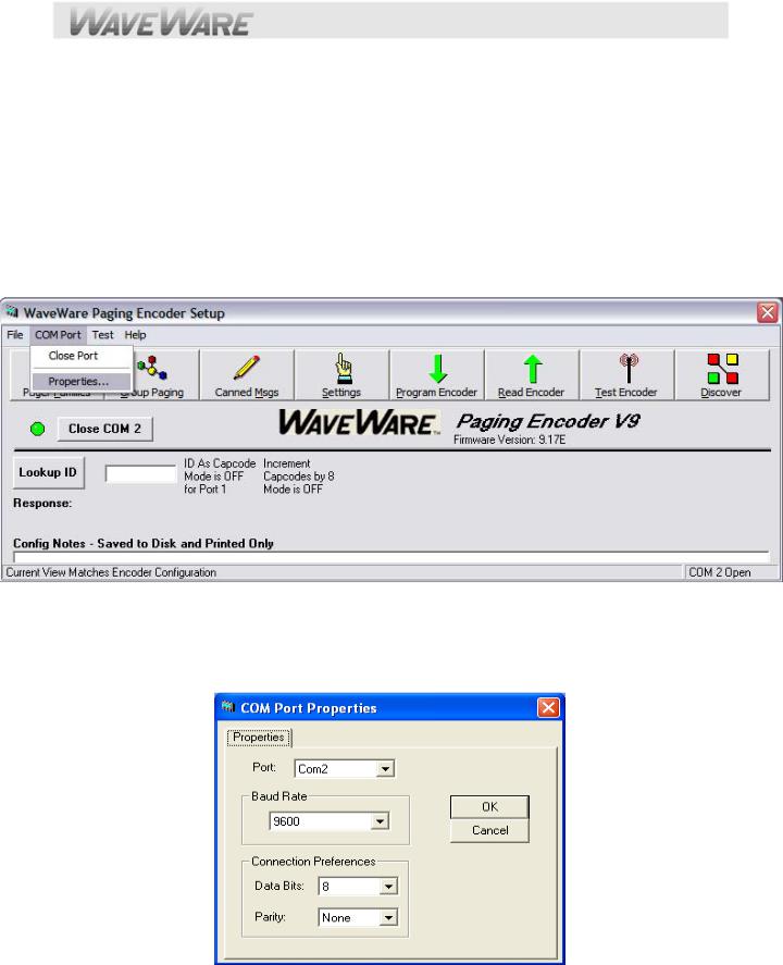
Start the SPS-5 v9 Encoder Setup Program and Click on the “Com Port” Button in the Menu and Click on “Properties”. See Fig. 1
Fig. 1 (Choose the Com Port, Part 1) If the Com Port Number is Wrong, Click “Properties” to Choose Port.
Com Port Settings Screen
Edit the “Com Port” and Settings and Click “OK”.
See Fig. 2
Fig. 2 (Choose the Com Port, Part 2)
Encoder Software Main Screen – Open Com Port
On the Main Screen of Encoder Setup Program, Click on the “Open Com (X)” Button next to the RED Light.

See Fig. 3
Fig. 3 (Open the Com Port, Part 1)…Click the “Open Com 2” to Open the Com Port.
The Software will detect the SPS-5 v9E Paging System and Open the Com Port and the Light will turn Green. See Fig. 4
Fig. 4 (Open the Com Port)
The Software has Opened the Com Port and will now READ the Database. Click “OK”
See Fig. 5
Fig. 5 (You MUST read the Database in order for the software to be able to display all of the settings in the paging system)
On the Main Screen of Encoder Setup Program, Click on the “Pager Families” Icon to Open the Pager Database. See Fig. 6
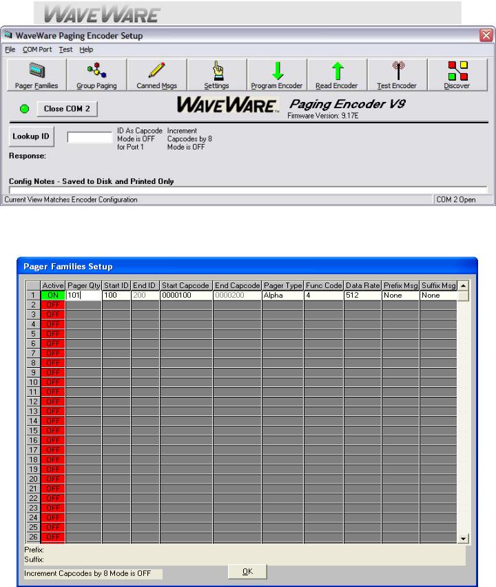
Fig. 6 (Open the Pager Database)…Configuration
Pager Families Screen: Enter Quantity, Pager ID’s, 7-Digit Cap Code, Baud Rate, Pager Type and Function code. |
|
Function Code 4 is normally for Alphanumeric Pagers and Function Code 1 is normally for Numeric Pagers. |
|
When Finished, Click “OK” |
See Fig. 7 |
Fig. 7 (Enter Pagers in the Database) If Family 1 is Red, Click to Activate and to Add Pagers, it will turn Green. For Programming of the Pager Groups – (See Next Page).

On the Main Screen of Encoder Setup Program, Click on “Group Paging” to Open the Pager Database. See Fig. 8
Fig. 8 (Group Paging)…Configuration
Pager Groups Screen: Enter The Group ID and list the pager ID’s you want in that group. The ID’s must be in the Pager Families, programmed previously. Note: In most cases you would use a “Common” Pager Cap Code in the Pager themselves instead of using Pager Groups. Using a Common Cap code will page all pagers at the same time; whereas using a group will page each pager one at a time, which is slow.
Pager Groups would be used primarily when “Timer Active” Mode is needed. When finished, Click “OK” See Fig. 9
Fig. 9 (Pager Groups Setup) If Group 1 is RED, click on the Box to Activate that Group, it will turn Green.
 Loading...