

Page 1

Paging Interface Adapter
Model PIA3264
Revision 1
Page 2

Paging Interface Adapter
Information in this document is subject to change without notice. Companies, names, and data used in examples
herein are fictitious unless otherwise noted. No part of this document may be reproduced or transmitted in any form
or by any means, electronic or mechanical, for any purpose, without the express written permission of comPPage,
Inc. All rights reserved. Printed in the United States. Microsoft, MS, Microsoft Windows XP are all trademarks of
Microsoft Corporation.
NOTIFICATION OF COPYRIGHT
This software package associated with the Paging Interface Adapter (“software”) is a proprietary product of
comPPage, Inc. and is protected by copyright laws and international treaty. You must treat the software like any
other copyrighted material, except that you may place the software on a single hard disk, provided that you keep the
original software solely for backup or archival purposes. Copyright laws prohibit making additional copies of the
software for any other reason.
SOFTWARE LICENSE AGREEMENT
Read this license Agreement before using the software. This agreement is a legal contract between you, the end user,
and comPPage, Inc. governing your use of the Software. This agreement shall also be binding on any subsequent,
authorized licensee. If you do not wish to agree to the terms of this Agreement, promptly return the complete
package to the distributor from whom you obtained this product. You will receive a full refund provided you return
the equipment in it
Original packaging. If you have any questions concerning this Agreement, contact:
comPPage, Inc.
Attn: Customer Service
6801 Lake Worth Road
Suite 308
Lake Worth, Florida 33467
LICENSE
1. comPPage, Inc.
2. You may not sub license, rent, or lease the software, but you may permanently transfer your license to use the
software and accompanying materials by delivering to another party the original diskettes and materials comprising
the software package, including the title page of the reference manual. You must also simultaneously destroy all
copies of the software and accompanying materials in your possession. Such transfer terminates your license to use
the software. The new recipient of the software and accompanying materials accepts this agreement and is licensed
under the terms of this Agreement upon initially using the Software.
3. You may not de-compile, disassemble, reverse engineer, copy, transfer, or otherwise use the software except as
stated in this Agreement.
® grants you the right to use the Paging Interface Adapter and software .
2
Page 3

Paging Interface Adapter
Table of contents
License..................................................................................2
Description...........................................................................4
Main board and contact logic card.....................................5
Change pc IP address .........................................................6
Change Log On and Password...........................................7
Change pia3264 IP Address................................................8
Global setting screen ..........................................................8
Programming .......................................................................9 - 11
Contact Input Screen...........................................................12
Development of Default Voltage Input File........................13 - 14
Development of Default Non-Voltage Input File................15 - 16
Reports .................................................................................17 – 19
Edit zone/room.....................................................................20
Mixed inputs.........................................................................20
Operation / Search...............................................................21
Block Diagram......................................................................22
Specification ........................................................................23
Installation............................................................................24 – 25
3
Page 4
Paging Interface Adapter
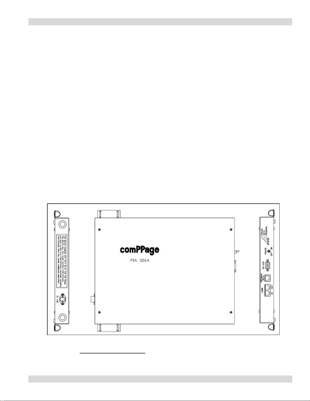
PAGING INTERFACE ADAPTER
PIA3264
PAGING INTERFACE ADAPTER
The Paging Interface Adapter unit is an alarm contact input device with 16 inputs and upgradeable to 64. The unit is
programmable by the user, using Microsoft™ Web browser program. Each unit has it own IP address. Simply enter
the IP address on the address line. All data is password protected. The PIA can be programmed from a stand alone
PC with an Ethernet card using a supplied RJ45 Crossover cable, or over the Local Area Network or any where from
the Internet.
The PIA has an added protection of sending a health check page every 2 minutes to alert the user the system is
operating properly.
The PIA will accept Dry (no voltage) contact closure or Voltage, high or low, input. Voltage input range is 6 to 50
volts AC or DC. Each input is fused to protect the inputs in case voltage is applied to a contact input that has been
configured for no voltage. Each contact can be configured for a different individual pager ID (cap code), Alert type
(A, B, C, or D) and repeats ranging from none, 1-4, or until Change of State. Time interval between repeats can be
select from 1 minute to 59 minutes. The paging protocol is a global setting of either Scope
COMP2 and
WaveWare
The PIA can be daisy chained together via RS485 Cat 5 RJ45 cabling to support up to 576 contact inputs.
comPPage’s Paging Interface Adapter (PIA3264) is a unit that was Designed, Developed and Manufactured in the
USA. Each unit has a
™. In addition the PIA supports shift changes, escalation of pages and 2 pulse rates.
Limited Lifetime Warranty.
™, Motorola™ TAP v1.8,
4
Page 5
Paging Interface Adapter
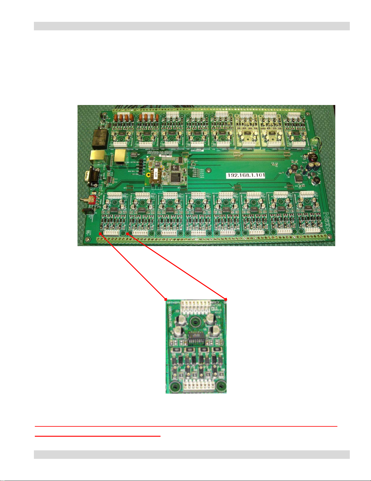
The Paging Interface Adapter (PIA3264) is upgradeable to 64 inputs by installing additional Logic Cards
(CTBD4) that will activate four inputs per card.
Main Board
Contact Logic Board
ENSURE ALL POWER IS REMOVED BEFORE INSTALLING OR REMOVING
THE CONTACT LOGIC BOARD
5
Page 6
Paging Interface Adapter
All IP addresses on a network or stand alone PC must have the same IP address string. Ie.. 192.168.1.100
and If your system does not support the IP series 192, which is the IP string address the PIA is shipped with
and can be found on the mother board. You must re-assign the PIA IP address to one that is compatible
with your network or PC or change the IP address on the PIA. This can be done by following the steps
below.
Note: Be sure to check with your network administrator before proceeding.
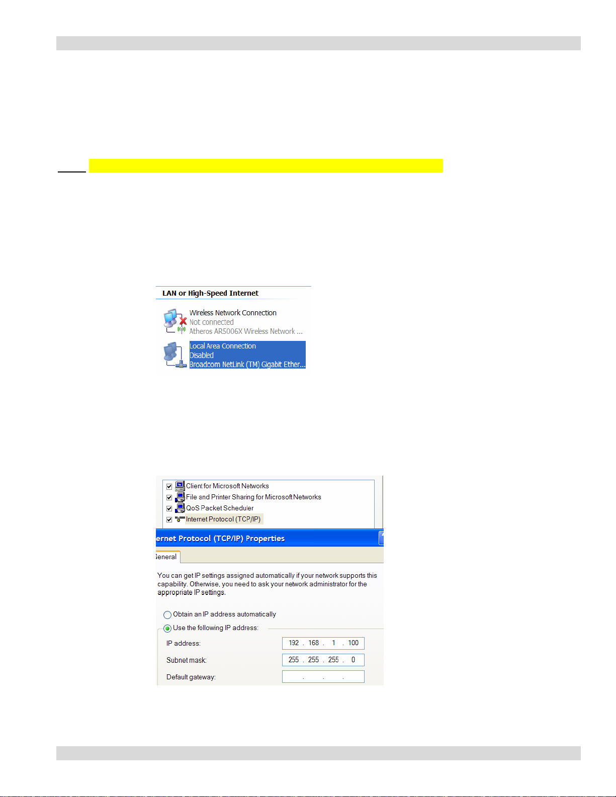
CHANGING PC IP ADDRESS
1. Locate the IP Address on the main board of the PIA3264, you will need to assign a
sequential number to the PC you are using to program the PIA.
2. Locate and Change IP Address.
a. Select Start, Connect To, Show all Connections.
3. Right click on your Local Area Connection and select Properties.
4. Right click Internet Protocol (TCP/IP) and select Properties.
5. Select Use the following IP address. This will un-select Obtain an IP address
automatically.
6. To the right of the IP address enter your new IP address. Be sure it matches the IP address
that is on the PIA. The Subnet mask should be 255.255.255.0. Select OK to exit the screen .
7. Re-boot your PC and you are ready to log onto the PIA.
6
Page 7
Paging Interface Adapter
DEFAULT USER ID and PASSWORD
The unit is shipped with a default log on User ID and Password. You should change the log on and
password before proceeding.
User Name: comppage
Password: pia3264
CHANGING USER ID and PASSWORD
1. Connect the PIA to a stand alone PC using the supplied Network Cross Over cable or connect to
your network hub using the supplied Network Patch cable.
2. Apply power to the PIA and turn on unit, the RED power light will illuminate.
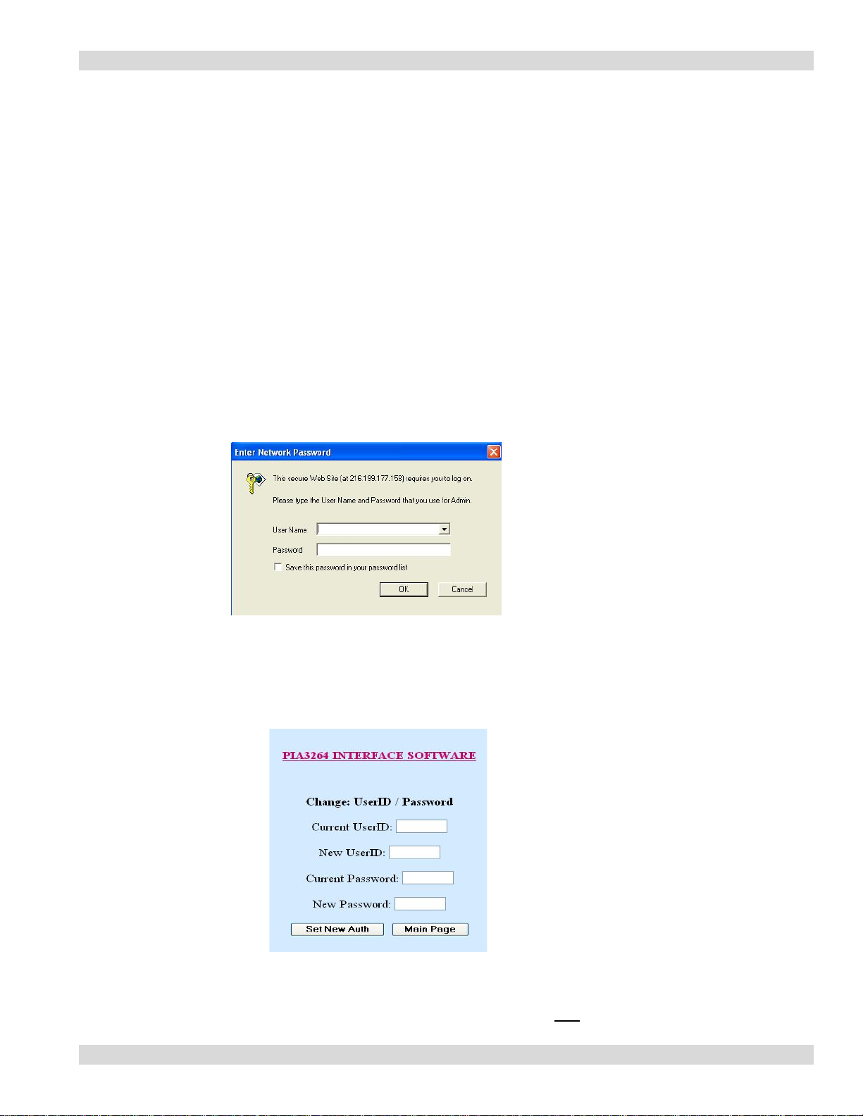
3. On the PC Internet Explorer Browser address line, enter the Paging Interface Adapter IP
Address.
The IP address can be found on the main board.
4. The following screen will appear.
5. Enter the default User Name and Password.
6. Click on OK.
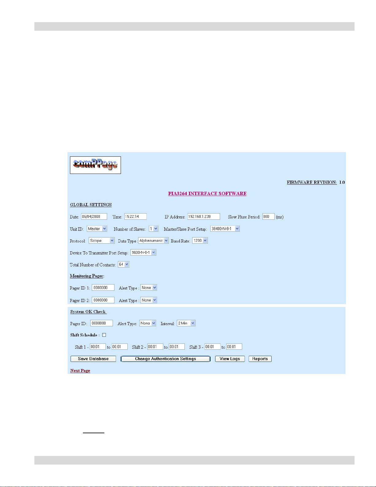
7. The Global Setting screen will appear.
8. Select the Change Authentication Settings button at the bottom of the screen.
9. The Change UserID/Password will appear.
10. After entering your new information, select Set New Auth.
11. The new information will be effective the next time you log onto the PIA3264.
12. Save this information in a secure place. If it is lost there is NO way to log onto the unit.
7
Page 8
Paging Interface Adapter
CHANGING PIA3264 IP ADDRESS
If the default IP address on the PIA3264 is not compatible with your network you need to access it from
the Internet browser screen and assign a new IP address. You must log on to the PIA3264 to change the
IP address.
1. Connect the PIA to a stand alone PC using the supplied Network Cross Over cable or connect to
your network hub using the supplied Network Patch cable.
2. Apply power to the PIA and turn on unit, the RED power light will illuminate.
3. On the PC Internet Explorer Browser address line, enter the Paging Interface Adapter IP
Address.
4. When the log on screen appears, enter your log on information.
5. The following screen will appear.
6. On the Global Setting page, in the space next to the IP Address, enter the new IP address you
want the unit to have. Be sure to record the new IP address some where, if you forget it there
is no way to access the PIA3264 once you log off.
7. After entering the new IP address, go to the bottom of the page and click on Save Database.
This will write the new address to memory.
8. You MUST cycle the power on the PIA3264 before the new IP address will be effective.
8
Page 9

Paging Interface Adapter
PROGRAMMING
Global Settings
All programming is accomplished on the Master unit.
Any Field not filled in will be disregard.
Date and Time
The unit has a RTC (real time clock). You must set the clock to the current time so all logs and
Reports will reflect the correct date and time.
1. Date – type the complete date including slash marks. (05/01/2008).
2. Time – the unit use a 24 hour clock. You must enter all digits include colons.(02:15:00)
IP Address
The Address of the unit being programmed.
Slow Pulse Period
This is the pulse rate for the host systems. Slow = 880 m/s. The program will automatically know
the Medium = 440 m/s. If the system has a faster rate than Medium, enter 440 m/s for slow and the
system will adjust the Fast for 220 m/s.
WARNING THIS SHOULD NOT BE CHANGED WITHOUT CHECKING WITH TECHSUPPORT.
Unit ID
Select the type of unit to be programmed. Each unit must be identified as a Master or Slave
1 thru 8.
1. Master
2. Slave 1 – 8
Number of Slave
Select the number of slaves that will be attached to the Master.
1. Slave 1-8
Master/Slave Port Setup
This setting is use to control the data speed on the RS485 bus. It is factory set and should only be
changed if you are have EXTREME difficulty with the master communicating with the slave units.
Paging Protocol
1. Select the paging protocol of the paging encoder installed.
a. Scope
b. Motorola Comp2
c. WaveWare
d. Motorola TAP V1.8™
™
™
™
9
Page 10

Paging Interface Adapter
Communications Port Parameters
This setting needs to match the port settings of the paging encoder.
1. 9600 n-8-1
2. 9600 e-7-1
3. 2400 n-8-1
4. 2400 e-7-1
5. 1200 n-8-1
6. 1200 e-7-1
Total Number of Contacts
Each PIA3264 has a capacity for 64 inputs. This selection is where you will select how many inputs
are installed in the unit you are programming. Example: 1 Master-16 inputs, 1-Slave 24 inputs.
1. Master with 16 inputs – Select 16 – All parameters and contact inputs are programmed on
the Master.
2. Slave with 24 inputs – Select 24 for total number of contacts and Unit ID – Slave and
select Save Database. That completes programming for the Slave. Repeat this operation for
each slave installed.
Monitoring Pagers
This option has two global pager IDs that can be identified so all alarm notification will be
sent to them as well as other pager IDs that are for specific alarms.
1. Enter Pager Cap Codes and Alert type [A,B,C or D].
Note: This option is not available when using Non-Voltage (Dry) input.
System OK Check
This selection allows the user to select a pager ID and Time Interval for the system to
transmit a SYSTEM OK check-in message.
1. Enter Pager ID. (after the screen has refreshed the leading zero will not be displayed, this is
Normal)
2. Enter Alert Type
3. Select the time interval.
Shift
This option allows for shift change paging automatically.
1. Check Shift Schedule
2. Select the start time of Shift One..ie 0730, select the ending time ..ie 1530.
3. Select the start time of Shift two. Ie 1530. Continue for all three shifts.
Note: The ending and start time of shifts will overlap. However, any call that
is activated during a 1 minute time frame of the overlap, will be sent to
both shifts paging receiver.
4. If the Shift three is not completely filled out to complete the 24 hour period, the
unused time will be considered as Shift three and any page during that time will
go to shift three pager.
Save Database
After selecting all the global settings, select SAVE DATABASE to write all the
parameters to the processor memory.
10
Page 11

Paging Interface Adapter
Function Button
1. Save Database Select to write programmed data to on board processor.
2. Monitor Alarms Allows the user to view real time alarm logging.
3. View Logs Allows the user to select a specific days log to view
4. Reports Select the appropriate report to view and print.
Contact Input Definition
1. Dry Normally Closed (N/C).
a. Active Message OPEN state.
b. Reset Message Closed State.
c. Repeats will occur on Open state.
2. Dry Normally Open (N/O)
a. Active Message CLOSED state.
b. Reset Message OPEN state.
c. Repeats will occur on CLOSED state
3. Voltage Alert Low
a. Active Message and Repeats when NO voltage is present.
b. Reset Message when voltage (6-50 Volts AC/DC) is present.
4. Voltage Alert High
a. Active Message and Repeats when Voltage IS present.
b. Reset Message when NO voltage is present.
Note: The above description of the contact inputs does not effect the installation using either
1 or 2 Pulse Rates. All functions of the unit will be triggered from the original selection
of Voltage High or Low. Pulsing is not available when Dry Contact input is selected.
11
Page 12

Paging Interface Adapter
Contact Input Screen
All contact programming is accomplished on the Master Unit.
Any field not filled in will be disregarded
Contact Input Programming
Each contact input can be programmed for individual messages for each state. The user can
select the type of input, Voltage or Non-Voltage and normal state of that contact. Each PIA is
shipped with 16 inputs standard, upgradeable to a total of 64 in blocks of 4. The unit can be
set for all voltage or all dry (no voltage). In addition the inputs can be divided into voltage and
dry inputs. If the unit is divided voltage and non-voltage, it must be in blocks of 4.
Example. 1-4 Voltage, 5-8 Dry.
12
Page 13

Paging Interface Adapter
Create Default File
All programming is inputted on the Master unit. The Slave only has to have a Unit ID and
Total number of Contacts identified.
Voltage Input
Start on Zone input #1
1. Select the Configuration of inputs.
a. Voltage
2. Select the Type of inputs. (see page 10 for definition)
a. Voltage Alert High
b. Voltage Alert Low
3. Enter Room No. 1-9999, if applicable
4. Enter Active Message
This is the message that will be sent to the pager when the zone is activated.
5. Enter Reset Message
This is the message that will be sent to the pager when the zone is reset.
Ie..Zone1 Alarm RESET or CANCELLED
6. Select the correct Pulsing rate from the Host System. (If applicable)
If not selected, the Pulse Message will not be available.
a. Slow – 880 m/s +/- 10%
b. Fast – 440 m/s +/- 10%
c. Enter Active Message if Pulsing is used.
7. Enter the message to be sent to the pager when Pulse 1 and Pulse 2 is activated.
8. If Shift was not checked on the Global Setting Page only shift 1 pager and Escalation
pager in the first column will be active. If Shift was selected on the Global Setting,
all three columns will be available.
a. Pagers for Shift 1 are shown on the first row .
b. Pagers for Shift 2 are shown on the second row.
c. Pagers for shift 3 are shown on the third row.
d. The Escalation pager ID is Global for all three shifts by call type.
13
Page 14

Active Msg Pager IDs
And Escalation Pager
7. Pager ID
a. If no pager number is required, the blank must have 7 zeros entered.
b. All protocol selections must have 7 digits entered in the pager ID blank.
Scope – 0100800, TAP – 0000100, WaveWare – 0000100, Comp2 – 0000100
8. Select the Repeat and Interval for contact.
a. Repeat 0 -5 or RUR (repeat until reset)
b. When RUR(repeat until reset) is selected, ESCALATION function is not
available.
c. Interval 2 ,5,10,15,20,30 Minutes, 1 or 2 hours.
9. Select Save Zone to -
a. Enter the range of zones on the unit you are programming.
Ie.. 1 to 24. This will write data to only the contact you will be using.
b. This will write the data to memory and refresh the screen.
c. Enter the range of zones on the Slave unit that will be attached.
10. Editing Default file using FIND ZONE
a. In the box next to Fine Zone, enter the number of the contact you want to
edit.
11. Select Fine Zone.
12. The zone information for the zone you entered will appear. You can now make changes.
13. Editing Default file using Prev or Next
a. In the box next to Fine Zone, enter the number of the contact you want
to edit.
b.. Select Fine Zone.
14. The zone information for the zone you entered will appear. You can now make changes.
15. Select Next to display the next input to be programmed
a. continue until all inputs have been programmed.
Paging Interface Adapter
Pulse One Pager IDs
And Escalation Pager
Pulse Two Pager IDs
And Escalation Pager
14
Page 15

Paging Interface Adapter
Non-Voltage Input (default)
Start on Zone #1
1. Select the Configuration of inputs.
a. Dry (non-voltage)
2. Select the Type of inputs.
a. Dry N/O
b. Dry N/C
3. Enter Room Numbers 1-9999 if applicable.
4. Enter the Active Message information.
5. Enter Reset Message Information.
6. If Shift was not checked on the Global Setting Page only shift 1 pager and Escalation
pager in the first column will be active. If Shift was selected on the Global Setting,
all three columns will be available.
a. Pagers for Shift 1 are shown on the first row .
b. Pagers for Shift 2 are shown on the second row.
c. Pagers for shift 3 are shown on the third row.
d. The Escalation pager ID is Global for all three shifts by call type.
Active Msg Pager IDs
And Escalation Pager
7. Pager ID
a. If no pager number is required, the blank must have 7 zeros entered.
b. All protocol selections must have 7 digits entered in the pager ID blank.
Scope – 0100800, TAP – 0000100, WaveWare – 0000100, Comp2 – 0000100
8. Select the Repeat and Interval for contact.
a. Repeat 0 -5 or RUR (repeat until reset)
b. When RUR(repeat until reset) is selected, ESCALATION function is not
available.
c. Interval 2 ,5,10,15,20,30 Minutes, 1 or 2 hours.
Pulse One Pager IDs
And Escalation Pager
Pulse Two Pager IDs
And Escalation Pager
15
Page 16

Paging Interface Adapter
9. Select Save Zone to -
a. Enter the range of zones on the unit you are programming.
Ie.. 1 to 24. This will write data to only the contact you will be using.
b. This will write the data to memory and refresh the screen.
c. Enter the range of zones on the Slave unit that will be attached.
10. Editing Default file using FIND ZONE
a. In the box next to Fine Zone, enter the number of the contact you want to
edit.
11. Select Fine Zone.
12. The zone information for the zone you entered will appear. You can now make
changes.
13. Editing Default file using Prev or Next
a. In the box next to Fine Zone, enter the number of the contact you want
to edit.
b.. Select Fine Zone.
14. The zone information for the zone you entered will appear. You can now make
changes.
15. Select Next to display the next input to be programmed
a. Continue until all inputs have been programmed.
Function Buttons Page Two
1. PREV Go back to the previous input zone.
2. NEXT Move to the next input zone.
3. SAVE ZONE Save all data to memory.
4. PRINT DATABASE Print a record of all information in current file.
5. PRINT ALARM LOG Select and Print a specific alarm log.
System stores 30 days of logs.
6. FIND ROOM Search feature, displays data for the room number entered.
7. FIND ZONE Search feature, displays data for the zone number entered.
8. SAVE TO ZONES Save displayed data to all zones entered.
When all programming is complete, select [PRINT DATABASE]. Retain this copy and
place a copy with the unit for any future questions or changes.
16
Page 17

Paging Interface Adapter
REPORTS
The system has the ability to store 30 days of data and produce four different types of reports. Each days
log is save using the Day, Month, and Year (01202008). If the user does not remove the logs from time to
time they the oldest will be written over and lost. These reports are selectable by choosing REPORTS
from the bottom of input screen one.
Database Report
The database report is a complete record of all currently programmed zones on the Master and Slaves, if
attached.
Database Report
Date: 12/31/2008 Time:00:00:00
Zone: 1 Active: Bed Call Assistance Needed Room 222
Reset: Bed Call Assistance Needed Room 222 Reset
Shift: 3
Pulse1: Y Slow Bath Call Room 222
Pulse2: N
Esc: Y
Repeat: 2/5
Zone: 2 Active:
Reset:
Shift:
Pulse1: Y Slow Bath Call Room 444
Pulse2: N
Esc:
Repeat: 2/5
Bed Call Assistance Needed Room 444
Bed Call Assistance Needed Room 444 Reset
3
Y
17
Page 18

Paging Interface Adapter
Report by Room number
The room number report is a list of all calls placed from a specific room, on a specific date.
ROOM 222 REPORT
ROOM No.
Report Date: 01/21/2008
Report Time: 14:22:00
Log Date: 01/20/2008
07:20:00 Bed Call Room 222
08:13:22 Bath Call Room 222
08:14:00 Bed Call Room 222 Canceled
08:22:23 Bath Call Room 222 Canceled
10:13:35 Bed Call Room 222
13:00:45 Bath Call Room 222
Report by Call Type and Room
This report the user can select a specific call type and room.
Bed Call Report:
Room No. 33
Report Date: 08/22/2007
Report Time: 16:22:00
Log Date: 07/20/2007
06:19:00 Bed Call Room 33
07:12:00 Bed Call Room 33 Reset
08:45:00 Bed Call Room 33
222
18
Page 19

Paging Interface Adapter
Elapse Time
This report allows the user to create a report for a specific room, day and calculate the elapse time for all
calls for that room.
Elapse Time Report:
Room No. 66
Report Date: 09/22/2007
Report Time: 18:00:00
Log Date: 11/20/2007
06:19:00 Bed Call Room 66 22 Minutes
08:45:00 Bed Call Room 66 13 Minutes
16:00:22 Bath Call Room 66 17 Minutes
19
Page 20

Paging Interface Adapter
EDIT
To change or remove information from a specific zone or room, follow the steps below.
1. Zone
a. Log on to unit.
b. Go to contact input screen.
c. In the blank next to the FIND ZONE enter the zone number you want to edit.
d. Select FIND ZONE.
e. The system will display the current data for that zone.
f. Edit the data and select SAVE ZONE.
2. Room Number
a. Log on to unit.
b. Go to contact input screen
c. In the blank next to ROOM NO enter the room number you want to edit.
d. Select Find Room.
e. The system will display the current data for that room.
f. Edit the data and select SAVE ZONE.
Note: After edit changes are saved, select Print Database. This will give you a complete list of all data on
all zones.
MIXED INPUTS
The PIA3264 has the ability to process different types of data on the same unit. This option allows the user
to select Non-Voltage(dry – N/O, N/C) and Voltage (High or Low). The user can selects VOLTAGE, or
Dry for each set of contact.
The rule being the contacts are in blocks of 4. If the user wants to have both Voltage and Dry inputs, the
inputs must be together in blocks of 4 inputs. Each CTBD4 logic card controls 4 inputs.
Example: Master with 16 inputs
Voltage: Contacts 1-4, 9-12
Dry: Contacts: 5-8, 13-16
20
Page 21

Paging Interface Adapter
OPERATION
1. Voltage Input
2. Voltage Alert High
3. No pulsing
4. No Shift
The system will continually scan all contacts at the rate of 1.5m/s. It senses a change on contact 1, the
voltage went from zero volts to +24vdc. The program will check the global programming parameters to
see if Shift, Monitor pagers are selected. If Shift is selected, it will check the clock and see what time the
alarm was activated, then compare that to the Shift schedule. This will determine what pager it pages. It
will select the Active Message and place it in the correct paging protocol that was selected on the Global
Setting page. Since this example Shift was not selected. The system will use the pager ID in Shift 1 entry.
SEARCH and DISPLAY DATA
Find Room
1. Enter the room number you want to find in the field next to Room No..
2. Select Find Room.
3. All programming for that specific room will be displayed.
Find Zone
1. Enter the zone number you want to find in the field next to Find Zone
2. Select Find Zone.
3. All programming for that specific zone will be displayed
21
Page 22

BLOCK DIAGRAM
Contact Input Logic Card
Paging Interface Adapter
22
Page 23

Paging Interface Adapter
SPECIFICATION SHEET
Model PIA3264
Operating Temperature -40C to +85C
Operating Voltage 12Volts DC (all units)
Maximum Operating Current
Serial Port Paging Protocol Scope, Tap v1.8, WaveWare
Comp2 with and without Alert type
FCC Approval Part 15
UL and Canadian Approval UL 1069, CSA (pending)
RoHS Compliant
Size 14 x 10 x 1.5 Inches
Weight
Serial Port RS232 9-Pin Male Sub “D”
Contact Input Voltage or Voltage Free
Contact Input Voltage 6 – 50 Volts AC or DC
Programmable RJ45 TCP Direct Connect,
Local Area Network or Internet
Interconnect of Units RJ45 Up to 8 Units via RS485
(total of 576 contacts)
23
Page 24

Paging Interface Adapter
INSTALLATION
Ensure power is NOT APPLIED to the unit before proceeding.
No Fuses = Voltage Input
Fuses = Non-Voltage(Dry) Input
1. Remove the four Phillips head screws located on top of the unit.
2. Remove the top cover and sit aside.
3. Using the hardware supplied, mount the PIA3264.
4. If the cable you are using has bundled wires, strip the outside covering back 24 inches.
5. Loop the cable in a U shape and attached by to the PIA3264 using the tie-wraps provided. Fig 1
6. Route the wire pairs through the access holes on the back of the unit.
7. With the front of the unit facing you, zones 1 - 32 are on the left and 33 – 64 are on the right. Fig 2
You should route your cables accordingly in order not to have to cross over the board inside.
Fig 1
24
Page 25

Paging Interface Adapter
Input 33 Input 64
+ +
Fig 2
+ +
Input 01 Input 32
8. If all the inputs have a common ground, it is not necessary to attach individual grounds to each input on
terminal block. Simply jumper attached the common ground to terminal number 2 and place an internal
jumper on the other terminals. (negative terminals: 2,4,6,8…etc)
9. Replace top cover and Phillips screws removed earlier.
10. Connect the power lead to rear of the unit.
11. Turn the power switch located on the front panel ON.
12. The power light will illuminate.
13. The PIA3264 is now in operation.
Slave
1. Connect the first slave to the master using a RJ45 Crossover Cable.
2. Connect the cable to the master RJ45 Out connector. Connect to the Slave to the RJ45 IN connector.
3. Each Slave is attached to another slave using a RJ45 Patch Cable.
25
Page 26

Fig 3 – Parts
Paging Interface Adapter
26
 Loading...