

Page 1

DVIF10
Page 2

Alarm Interface Utility Software V3.1.3
Information in this document is subject to change without notice. Companies, names, and data used in examples herein
are fictitious unless otherwise noted. No part of this document may be reproduced or transmitted in any form or by any
means, electronic or mechanical, for any purpose, without the express written permission of comPPage, Inc. All rights
reserved. Printed in the United States. Microsoft, MS, Microsoft Windows XP are all trademarks of Microsoft
Corporation.
NOTIFICATION OF COPYRIGHT
This software package (“software”) is a proprietary product of comPPage, Inc. and is protected by copyright laws and
international treaty. You must treat the software like any other copyrighted material, except that you may place the
software on a single hard disk, provided that you keep the original software solely for backup or archival purposes.
Copyright laws prohibit making additional copies of the software for any other reason.
SOFTWARE LICENSE AGREEMENT
Read this license Agreement before using the enclosed software. This agreement is a legal contract between you, the end
user, and comPPage, Inc. governing your use of the Software. Installing the accompanying software package indicates
your acceptance of this Agreement. This agreement shall also be binding on any subsequent, authorized licensee. If you
do not wish to agree to the terms of this Agreement, promptly return the complete software package, with disk(s) to the
distributor from whom you obtained this product. You will receive a full refund provided you return the full Software
package, and the disk package is unopened. If you have any questions concerning this Agreement, contact:
comPPage, Inc.
Attn: Customer Service
6801 Lake Worth Road
Suite 308
Lake Worth, Florida 33467
LICENSE
1. comPPage, Inc. grants you the right to use one copy of the Dry & Voltage Interface
computer, or on a single terminal workstation.
2. You may not sub license, rent, or lease the software, but you may permanently transfer your license to use the software
and accompanying materials by delivering to another party the original diskettes and materials comprising the software
package, including the title page of the reference manual. You must also simultaneously destroy all copies of the software
and accompanying materials in your possession. Such transfer terminates your license to use the software. The new
recipient of the software and accompanying materials accepts this agreement and is licensed under the terms of this
Agreement upon initially using the Software.
3. You may not de-compile, disassemble, reverse engineer, copy, transfer, or otherwise use the software except as stated
in this Agreement.
software on a single-user
2
Page 3
Alarm Interface Utility Software V3.1.3
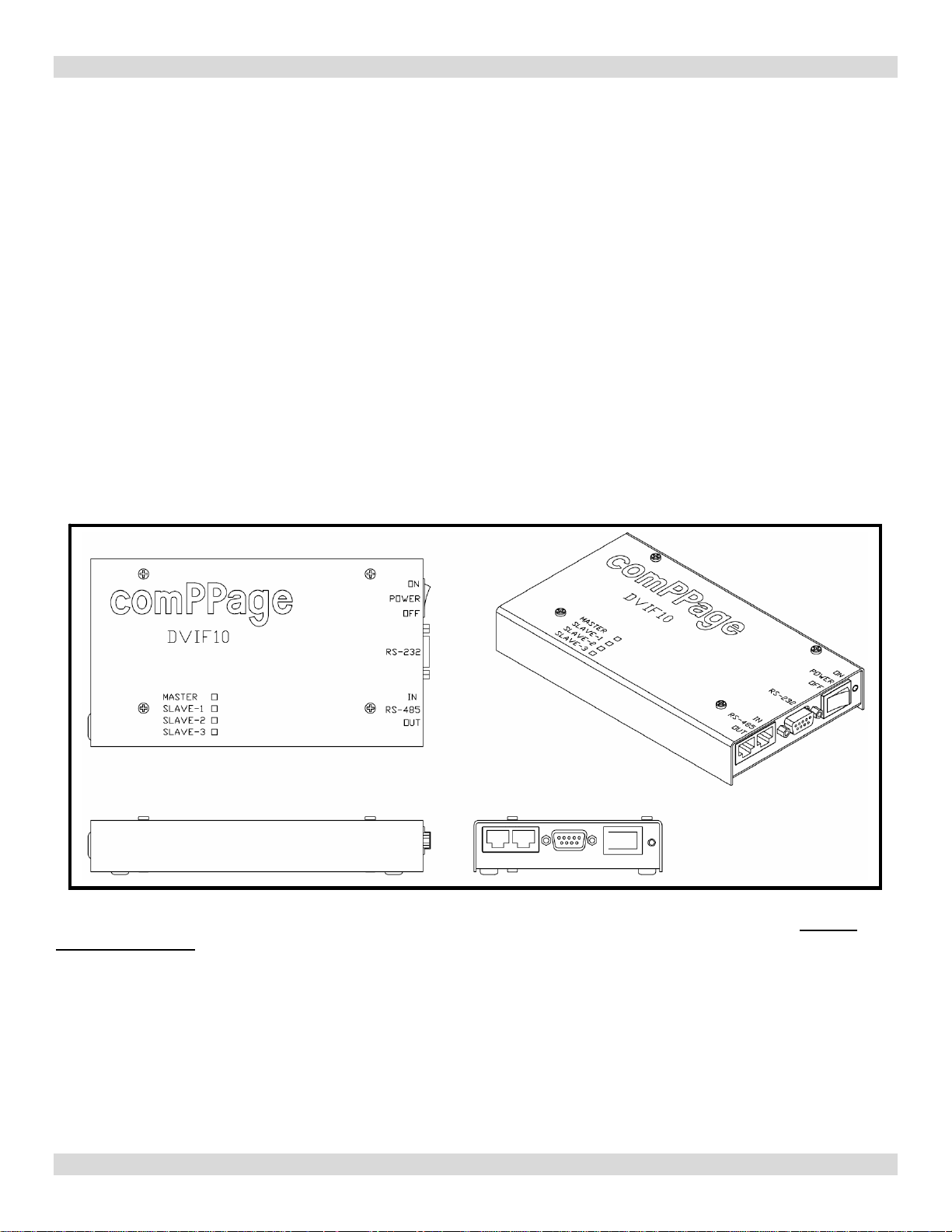
DRY VOLTAGE INTERFACE 10
DVIF10
The Dry Voltage Interface 10 (DVIF10) is an alarm contact input device with 10 inputs that is PC programmable by the
user, using the supplied Microsoft Windows™ compatible software program. The DVIF10 will accept Dry (no voltage)
contact closure or Voltage, high or low, input. Voltage input range is 1 to 24 volts AC or DC. Each input is fused to
protect the inputs in case voltage is applied to a contact input that has been configured for no voltage.
Each contact can be configured for a different individual pager ID (cap code), Alert type (A, B, C, or D) and repeats
ranging from none, 1-4, or until Change of State. Time interval between repeats can be select from 1 minute to 59
minutes. The paging protocol is a global setting of either Scope
to send either Alphanumeric or Numeric messages.
The DVIF10 can be daisy chained together via RS485 Cat 5 RJ45 cabling to support up to 40 contact inputs.
The Dry & Voltage Interface program will run on Microsoft Windows™ XP home or professional and the new Vista.
comPPage’s DVIF10 is a unit that was Designed, Developed and Manufactured in the USA. Each unit has a
Lifetime Warranty
.
™ or Motorola™ COMP2. In addition the user can select
Limited
3
Page 4
Alarm Interface Utility Software V3.1.3
INSTALLATION
1. Insert CD into the CD-R or CD-RW drive, the CD will auto start.
2. If auto start does not function, Select [START], [RUN] type in {cd-rom drive letter and enter SETUP.EXE.
3. Press OK.
.
SETUP
1. Connect the DVIF10 to a computer using the supplied Null-modem cable.
2. Open the Alarm User Interface program
3. Turn on the DVIF10 unit.
4. Select the communication port the DVIF10 will be connected to. [Serial Output].
5. Select the baud rate of the port using the drop down menu [Devise to transmitter baud rate].
6. Select [Connect] the Red will turn Green when connected and the label will turn to [Disconnect].
If you have made a mistake and selected the wrong communication port, simply click on the word
Disconnect and reselect the communication port. The program LED on unit will light.
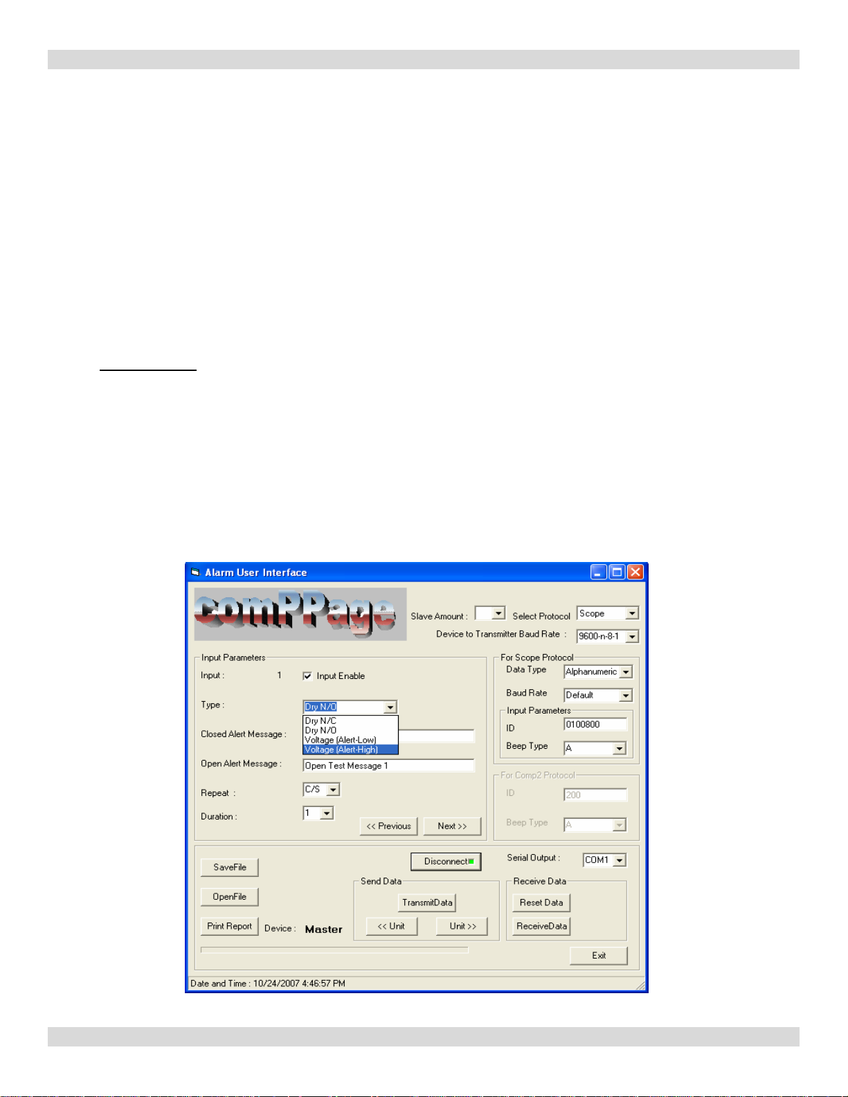
Scope Protocol
1. Select Slave Amount 0=None or 1,2,3.
2. Select Scope paging protocol and serial port baud rate and parity.(Device to Transmitter Baud rate)
3. Select Data Type and Baud Rate (pager – 512, 1200. Default = 1200)
4. Select [Input Enable] for input 1. You must do this for each input 1-10.
5. Select the type of input. Each input can be different. See [Type:].
6. Enter Closed message and pager ID, beep type for each input.
7. Enter Open message. The Pager ID, beep type will be the same for Open and Closed State.
8. Select the number of repeats and duration between each repeat or C/S (Change of State)
9. Select [Next].
10. Complete 2-6 for each contact input.
4
Page 5
Alarm Interface Utility Software V3.1.3
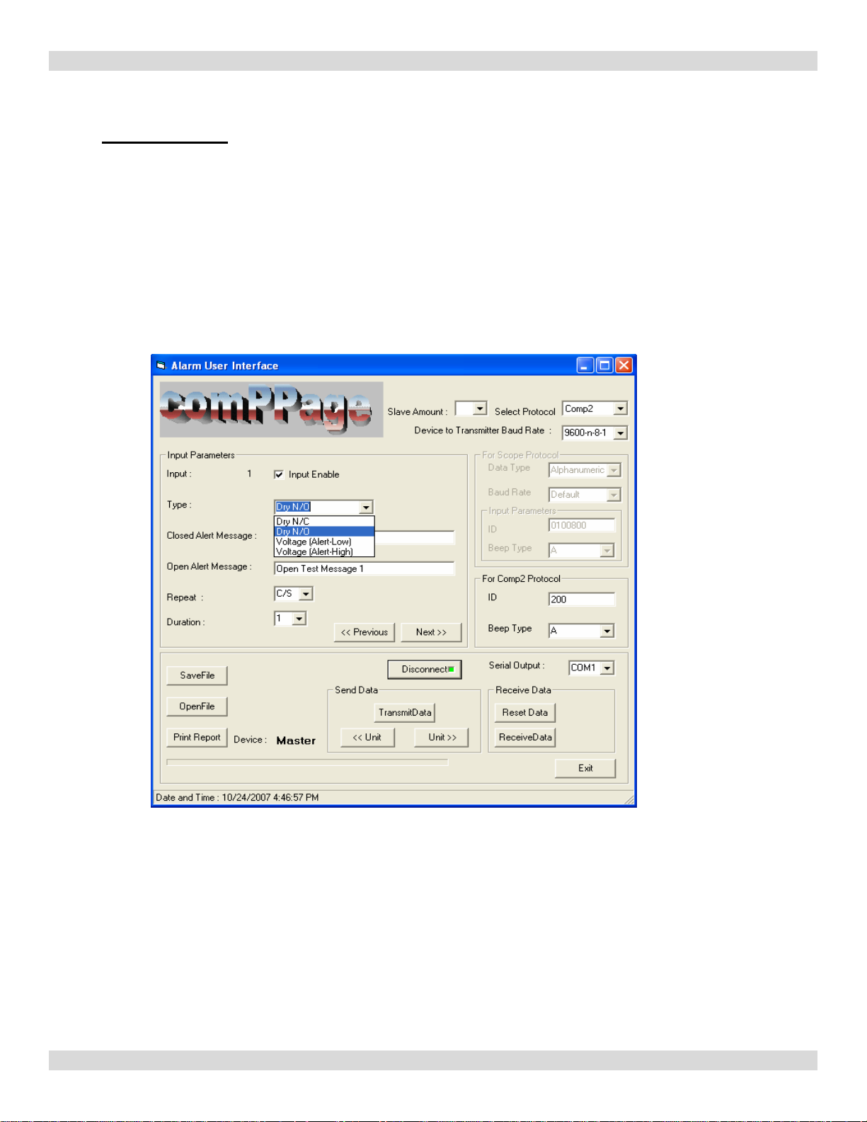
COMP2 Protocol
1. Select Slave Amount, 0=None, 1,2,3
2. Select Comp2 paging protocol and serial port baud rate and parity.(Device to Transmitter Baud rate)
3. Select [Input Enable] for input 1. You must do this for each input 1-10.
4. Select the type of input. Each input can be different. See [Type:].
5. Enter Closed message and pager ID(three digits), beep type under [For Comp2 Protocol].
6. Enter Open message Pager ID, beep type will be the same for Open and Closed state.
7. Select the number of repeats and duration between each repeat.
8. Complete 2-6 for each contact input.
5
Page 6

Alarm Interface Utility Software V3.1.3
NOTE: WHEN WRITING or READING FROM THE DVIF10 ALWAYS USE A NU LL MODEM CABLE
Writing Data to Unit
1. After programming of all contacts select [SaveFile] and enter a name for the file.
2. Select [TransmitData]. During writing to the unit a progress bar will appear at the bottom
of the screen.(Sending Data to the Alarm Unit..).
3. The Green light will change to Red when transfer of data is complete and the Green program
LED on the DVIF10 unit will turn OFF.
Print Report
1. Select [Print Report].
2. Printer dialog box will appear. Select the printer.
3. Print Report.
4. Select [EXIT] to close Alarm Program.
6
Page 7

Alarm Interface Utility Software V3.1.3
Single Unit Installation
1. Mount DVIF10 in selected location with supplied hardware.
2. Connect Alarm inputs to the DVIF10.
3. Connect DVIF10 to Transmitter using the cable supplied.
Note: All Scope equipment requires a Null Modem Cable. Other Equipment uses a Standard
Serial Cable (straight through).
a. When using the Scope ConneXions Transmitter No External Power is required.
b. When using the following paging transmitters, External Power is required.
1). Scope XLUSA
2.) SPS5V7
3.) TX125-EN
4. Turn on the DVIF10 alarm unit.
Note: It takes approximately 1:40 minutes after power up for the DVIF10 to initialize.
5. Test DVIF10 alarm unit by triggering an alarm.
6. Programming and installation complete.
Reading Data from DVIF10
1. Using the Null Modem DB9 to DB9 Female cable, connect the DVIF10 to a PC.
2. Open the Alarm Program.
3. Turn on the DVIF10.
4. Select the COM Port and click Connect.
5. The programming LED on the unit will turn ON and the connect button will turn GREEN.
6. Ensure the
7. Click Receive Data.
8. During reading from the unit a progress bar will appear at the bottom of the screen, which informs
user about the status of the data received, and the unit(master or which slave) it received data from.
9. At the completion , the programming LED on the unit will turn OFF and the program will
request the user to Save the Received Data in a file. The user will give the file a name or
select the name of a Saved file.
10. The User will be prompted to Open the file. Select the same name used step 7..
11. The data will be displayed in the program.
12. The user can now make any changes.
13. If additional units are to be read, unplug the unit and connect the next unit to be read.
14. Follow steps 4-8 until all units have been read.
contact counter is set to 1. If not you will get an error message.
Modify Data
1. After reading data from the DVIF10 using steps described in Reading Data from DVIF10.
2. Enter new data.
3. Cycle power on the DVIF10.
4. Click the Connect button on the Alarm program.
5. Once connected, click Transmit Data.
6. When data transmit is complete, Power off the DVIF10.
7. Disconnect DVIF10 from the PC.
8. Exit Alarm Program.
9. Connect DVIF10 to paging transmitter.
10. Power ON DVIF10. Note:
It will take approximately 1:40 minute for the DVIF10 to initialize.
7
Page 8

Alarm Interface Utility Software V3.1.3
Master and Slave Procedure
Each unit must be programmed separately. The master will have contacts 1-10 and the first slave
will have 11-20 and so on for each slave. Once you have selected the number of slaves in the software
and programmed the master with all 10 inputs, disconnect the master unit and connect the first slave
Continue programming following the below listed steps. Mark the top of each unit with its appropriate
designation. (Master or Slave)
1.
Programming using a Pre-Saved file. (1-Master, 1-Slave)
a. Connect the Master DVIF10 to the programming PC with the supplied Null Modem Cable.
b. Open Alarm Program
b. Turn [ON] power to Master Unit.
c. Select [Open File], click on file you want to use and select [Open].
d. Note at the top of the program screen, the [Slave Amount] should display the correct
number of attached slave units you are programming.
e. Device should display [Master].
f. Select the communication port [Serial Output] and click the [Connect ] button.
g. The programming LED on the master unit will light and the [RED] button will turn
[GREEN].
h. Click [TransmitData].
i. During data transfer y ou will see a progress bar, when completed the programming
[LED] on the unit being programmed will turn off and the [Green] button on the
program will turn [Red].
j. Power off the Master and Unplug the unit. Connect the slave unit to be programmed.
k. Turn [ON] the slave.
l. Select next [UNIT] and the display will show [SLAVE1].
m. Click the [Connect ] button, it will turn [Green].
n. Click [TransmitData].
o. During data transfer you will see a progress bar, when completed the programming
[LED] on the unit being programmed will turn off and the [Green] button on the
program will turn [Red].
Note: If using additional Slave units, Unplug the unit programmed and connect the next Slave. Select
Next Unit by clicking the Unit button. Follow steps g thru o for each unit to be programmed. If no more
units are to be programmed continue.
p. Disconnect the unit from the programming PC.
q. Power off the unit.
r. Exit the Alarm Program.
Ensure the Contact counter is on 1.
8
Page 9

Alarm Interface Utility Software V3.1.3
Installing Master and Slave Units for Paging
Note: Ensure jumper settings are correct for the paging transmitter you are using.
See jumper setting chart page 10.
1. Scope ConneXions 2 - XLite Paging Transcoder – SPS5V7
a. Mount Master and Slave Units.
b. Connect alarm inputs for all units.
c. Connect the
d. Power ON the Scope ConneXions transmitter.
e. Connect the Cat 5 Cross Over Cable from the Ouput RS485 RJ45 connector of the
master to the first Slave units, input RJ45 connector.(see diagram 1)
f. If additional slaves are installed connect using standard Cat 5 cable, from output to
input RJ45 connectors.
g. Power on the Slave unit(s), then the Master. If this procedure is not followed the units
will not initialize. It will take approximately 1:40 minutes for the unit to initialize.
h. Test Units.
2. TX125EN Paging Transcoder
a. Mount Master and Slave Units.
b. Connect alarm inputs for all units.
c. Connect the
d. Power ON the paging transmitter.
e. Connect the Cat 5 Cross Over Cable from the Output RS485 RJ45 connector of the
master to the first Slave units, input RJ45 connector.(see diagram 1)
f. If additional slaves are installed connect using standard Cat 5 cable, from output to
input RJ45 connectors.
g. Power on the Slave unit(s), then the Master. If this procedure
will not initialize. It will take approximately 1:40 minute for the unit to initialize.
h. Test Units.
DB9 Null Modem cable from the Master unit to the Paging Transmitter.
DB9 Serial Cable from the Master unit to the Paging Transmitter.
Inputs
1. Dry Normally Closed (N/C).
a. Alarm Message OPEN state.
b. Reset Message Closed State.
c. Repeats will occur on Open state.
2. Dry Normally Open (N/O)
a. Alarm Message CLOSED state.
b. Reset Message OPEN state.
c. Repeats will occur on CLOSED state
3. Voltage Low (N/O)
a. Alarm Message when voltage (1-24 Volts AC/DC) is Applied (closed Alarm).
b. Reset Message when voltage (1-24 Volts AC/DC) is Removed (open Normal).
c. Repeat will occur when voltage is Applied. (closed)
4. Voltage High (N/C)
a. Alarm Message when voltage (1-24 Volts AC/DC) is Applied (closed Normal).
b. Reset Message when voltage (1-24 Volts AC/DC) is Removed (open Alarm).
c. Repeat will occur when voltage is Removed (open).
Note: See Diagram 2 Page 13.
is not followed the units
9
Page 10

Alarm Interface Utility Software V3.1.3
Jumper Setting
DVIF10 (Single or w/Slave) Scope Transmitters On Slave 2 & 3
Cable Null Modem
Jumper - Shorted JP1, JP2, TP4, J5, JP14
Jumper – Removed JP13, JP15
Jumper - Pins 1 & 2 , JP16, JP17
DVIF10(Single or w/Slave) SPS5V7 and TX125-EN On Slave 2 & 3
Cable Standard Serial Straight Through
Jumper - Shorted JP1, JP2,
Jumper – Removed TP4, J5, JP13, JP14, JP15
Jumper - Pins 1 & 2 , JP16, JP17
TP4
J5
JP16
JP17
PIC Processor
Cat 5 Standard LAN
TP4 J5, JP14
JP1, JP2, JP13, JP15
Same
Cat 5 Standard LAN
JP1, JP2, TP4, JP19, JP13,14,
JP15
Same
Fuses
Contact Input Voltage or Dry (no voltage)
5. Dry Normally Open (N/O)
a. Alarm Message CLOSED state.
b. Reset Message OPEN state.
c. Repeats will occur on Closed State.
Top to Bottom
JP13, JP14, JP15
Contact Input Fuse 25vdc/450mA JP1
Input Terminal Block 1-10 JP2
Input Jumpers
No Jumper - Voltage
Jumper – No Voltage
10
Page 11

Specifications
Input Voltage 12 Volts DC
Current 750 mA maximum, Normal – 425mA
Input Contacts 10 per unit, Maximum 40
Input Selection No jumper Voltage
Input No Voltage (dry)
Connection RJ45 Cable using RS485 Total 4 Units
Protocol Scope and Motorola Comp2
Programming PC software via RS232 9 pin connector
Repeat Message 0-4 or Change of State, with intervals of 1-59
Message Open state and Closed state
Message Length Each message has a maximum length of 80
Pager Cap Code Each Contact has Individual Pager ID
Message Alert Type A,B,C or D selectable for each Contact
Approval FCC Part 15, RoHS Compliant
Size 7.10 in x 3.52 in x 1.17 in
Warranty Life
RS232 Cable Pin Out
Null Modem (Special)
9-Pin F/F
Serial Straight Through
9-Pin M/F
Alarm Interface Utility Software V3.1.3
Jumper Dry
Fused Inputs – 125 Volts DC / 450mA
Voltage – AC or DC 1-24 Volts
Inputs can be Mixed
minutes
characters
1-nc, 2-3,3-2,4-6,6-4,5-5,7-8,8-7, 9-9
1-1,2-2,3-3,4-4,5-5,6-6,7-7,8-8, 9-nc
11
Page 12

Alarm Interface Utility Software V3.1.3
Diagram #1
Serial Cable to Paging
Transmitter
Cat 5 LAN
Cross Over Cable
Cat 5 LAN
Standard Cable
To next Slave
Unit.
12
Page 13

Diagram #2
Alarm Interface Utility Software V3.1.3
13
Page 14

Alarm Interface Utility Software V3.1.3
14
 Loading...