

Page 1

WaveWare Technologies, Inc.
“We Deliver Information at the Speed of Light”
Call Manager Software
Call Manager Setup Manual
Table of Contents
Title
Software and Manual Overview
Additional Information and PC Requirements
Registration / Activation Information
How to Install and Register / Activate the Software
Install / Download From the WaveWare Software CD 4
Check the PC Com Ports (Free Utility Software) 6
Install / Download From the WaveWare Website 7
Registering / Activating Enterprise Server Software 7
Configuring the Call Manager Software
Configure:
Step 1 – Inovonics Com Port Choose the Com Port for the Central Receiver 13
Step 2 – Input Com Port Choose the Com Port for the Wired Call System 14
Step 3 – Input Protocol Choose the Port Protocol for the Wired Call System 15
Step 4 – Output Com Port Choose the Com Port for Connecting the Paging System 16
Step 5 – Email Server Setup and Test the Email Server 17
Define:
Step 6 – Message Recipients Assign Pagers and Email Addresses to Recipients 19
Step 7 – Call Device Types Add the Types of Call Devices to be used 21
Step 8 – Rooms / Residents Add the Room Number and Name of Resident 22
Register:
Step 9 – Call Devices Add Call Devices (EX: Wireless Inovonics and Wired Call Systems) 24
Step 10 – Receivers Add the Receivers (EX: Central Receiver and all Repeaters) 29
Define:
Step 11 – Stations Add Stations (EX: Nurses Station, Therapy, X-Ray, Etc.) 30
Assign:
Step 12 – Pagers to Stations Choose the Pagers / Recipients Associated with a Station 31
Step 13 – Rooms to Stations Choose the Rooms Associated with a Station 32
Configure:
Step 14 – Scheduling Reports Create / Name / Choose Report Template, Recipients, Schedule 33
Settings:
Step 15 – General Shift Start Times, Report Values, Call Notification, Passwords, LED Sign Output 36
Monitor Window - Monitor Serial Port Activity – Verbose Logging
Alerts Screen - View Active Alerts, Maintenance Alerts, Removing and Acknowledging Alerts
Report Type and Generator - Choose Report Filtering and Generate the Report
Assign Screen - Call Devices - Assign, Un-Assign and Re-Assign Call Devices to Rooms
Troubleshooting - Error Messages - Inovonics Receiver, Paging System and Tamper Alerts
Page
2
2
3
4
12
38
39
41
46
47
Page 2

WaveWare Technologies, Inc.
“We Deliver Information at the Speed of Light”
Call Manager Software
Software Overview
Call Manager Software is Designed to Monitor Service Call Requests from Both Inovonics Wireless Transmitters
and from Wired Call Systems, while Notifying Call Activation and Deactivation Events via Pager and LED
Message Board, while Logging the Event History. A Report Generation Utility is also provided.
Manual Overview
This Manual is to Explain How to Install, Register and Configure the Software.
The Call Manager Software is Available to be Purchased “Pre-installed” on a Desktop PC (Optional)
- If Not Ordered “Pre-installed” on a Desktop PC -
Install the Call Manager Software on a “Desktop” Computer.
The PC doesn’t have to be a Dedicated Desktop Computer and Do Not use any “Server” Model Computers.
The Call Manager Software ONLY works properly on a “Standard Desktop” Computer.
It is NOT recommended to install on a SERVER Model Computer.
WaveWare Does Not Support Real Servers or Server Operating Systems or Computer Terminals.
WaveWare Does Not Support Virtual Machines or Tablets, at this time.
WaveWare Only Supports: Windows XP Pro SP2 or SP3 and Windows 7 Pro SP1
(We Do Not Support Vista or Windows 8).
Additional Information:
Note: Call Manager Software is Designed to Operate with Wired Call Systems that Perform Repeat Paging during
Active Calls and Do Not Output a Call Cancellation Message when the Call is Cancelled.
At the End of this Manual you will find Diagrams to illustrate how the installed components work together.
Desktop PC Requirements:
The Minimum Hardware Requirements for use with WaveWare Call Manager Soft ware are:
1 Desktop Model PC with…
1+ GHz Processor
10+ GB Hard Drive
1+ GB Memory
3+ RS-232 Serial Com Ports
1 Ethernet Port
1 CD-ROM
Please Note: Additional RS-232 Serial Com Ports may be needed depending on Application Requirem ents.
2
Page 3

Registration and Activation Information:
WaveWare Support “Strongly Recommends” Requesting a Fully Functional “Trial” Activation Key to Start.
This is in case the customer (the end user) finds that the PC they chose is “Not” the one they will use. This could
be for many different reasons: Not happy with the Performance, or decide to use a different PC a nd/or maybe in a
different location within the building or during testing of the Software the PC just wouldn’t work properly as
required or it died, etc.
Requesting a DEMO Key will “Save” the Customer a Permanent Key, in case it is needed sometime in the Future,
as ONLY 2 Activation Keys are allowed per Purchase.
Please Note:
It is Suggested that Both the Dealer and the Customer Save a Copy of the Software and the Registration Key.
NOTE: If you have No Activations Keys left to use, WaveWare may Re-activate the Software if you have the
Original Software Version and if No Technical Assistance is required.
If you need Technical Assistance, you will need to Re-Purchase the Software to Upgrade to Latest Version.
We Do NOT Support Multiple User Log-ins.
(But, Try and Install the Activation Key for each User for the same PC, as this may work)
IMPORTANT
WaveWare Software “Requires” Administrator Privileges to work properly.
Required Information:
The Customer (End User) Company Name is “Required” Information when sending a PO to Order our Software.
This same Information along with the Dealer Name who sold the Software and Software Version is also
“Required” when sending WaveWare the “Request Key” or the “Activation Key” will be Delayed.
All Information Must match the PO on Record for this Application, or it will Delay Activation / Registration.
For Support:
Users please call your Software Dealer who sold you the Call Manager Software.
Dealers may contact WaveWare Technologies at:
WaveWare Technical Support at: 1.800.373.1466 x216 or support@wirelessmessaging.com
WaveWare Website: www.WirelessMessaging.com
Next: How to Install and Activate the Call Manager Software
3
Page 4
WaveWare Technologies, Inc.
“We Deliver Information at the Speed of Light”
Call Manager Software
Installation and Activation
This Section is to Explain How to Install and Register/Activate the Software.
Downloading Call Manager from the WaveWare Software CD
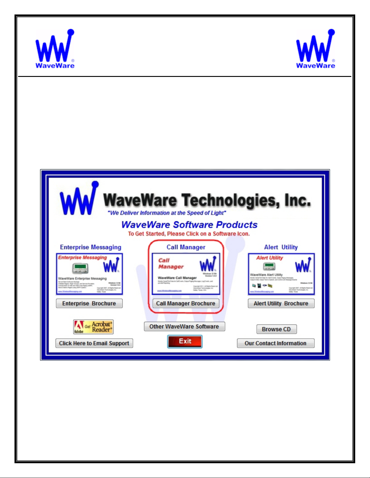
If you Received a WaveWare Software CD, place it into your PC’s CD-Rom Drive and when the CD Auto-Starts,
Click on the “Call Manager” Icon on the Main Screen. See Fig. 1
Fig. 1
IMPORTANT
It is Recommended that you keep the WaveWare Software CD in a Safe place for Futu re re-installs.
Or “Save” a Copy of the “Install Files” on the CD in a Safe Place.
NOTE: Without the CD or Original Version of the Install Files, you will need to Re-Purchase the Software, if you
ever Require Re-installation of the Software.
4
Page 5
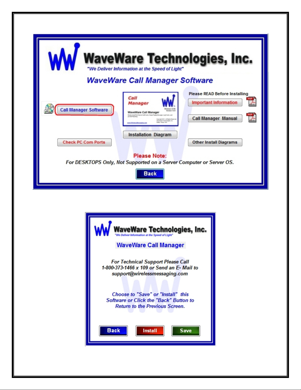
On the following screen: Click on the “Call Manager Software” Button. See Fig. 2
Fig. 2
Choose to “Save” the Software to a Folder on the PC or “Install” to start the Installation. See Fig. 2A
Fig. 2A
5
Page 6
Check for Available Com Ports
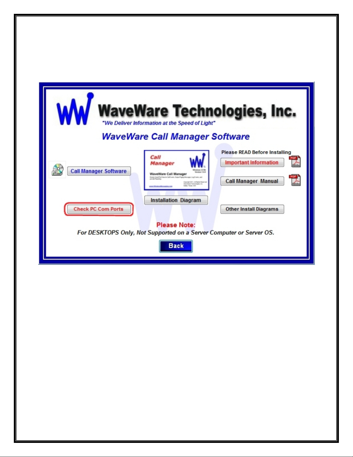
This Utility will Search the PC for Serial Com Ports and give the Availability and Status of each.
If you are not sure of the com ports installed on the PC…
Click the “Check PC Com Ports” Button, then Click Run. See Fig. 3
Fig. 3
Download Call Manager from the WaveWare Website is next.
6
Page 7
Download Call Manager from WaveWare Website
Download the Call Manager Software from the WaveWare Website and save to a Folder on the Desk top PC.
Website: http://www.wirelessmessaging.com/wavewaresw.html
Please, be sure to “Download and Save” the Software to a Folder, to use for any Future re-ins talls.
It is highly “Recommended” that you “Keep a Copy” of the Call Manager Software in a Safe place.
NOTE: Without the Originally Purchased Software “Version”, you will need to “Re-Purchase” the Software.
Registering/Activating Call Manager Software
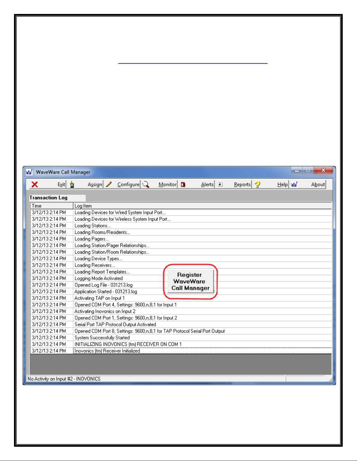
After Installing the Call Manager Software, Start the Software for the First time.
You should see the “Register WaveWare Call Manager” Icon in the Center of the Screen.
Click, on the Register Icon. See Fig. 4
Fig. 4
If the above Screen with the Register Icon is seen, after Clicking the Icon, Jump to Page 7.
If you Do Not see the Register Icon, Please Continue to the next Page to Register the Software.
7
Page 8
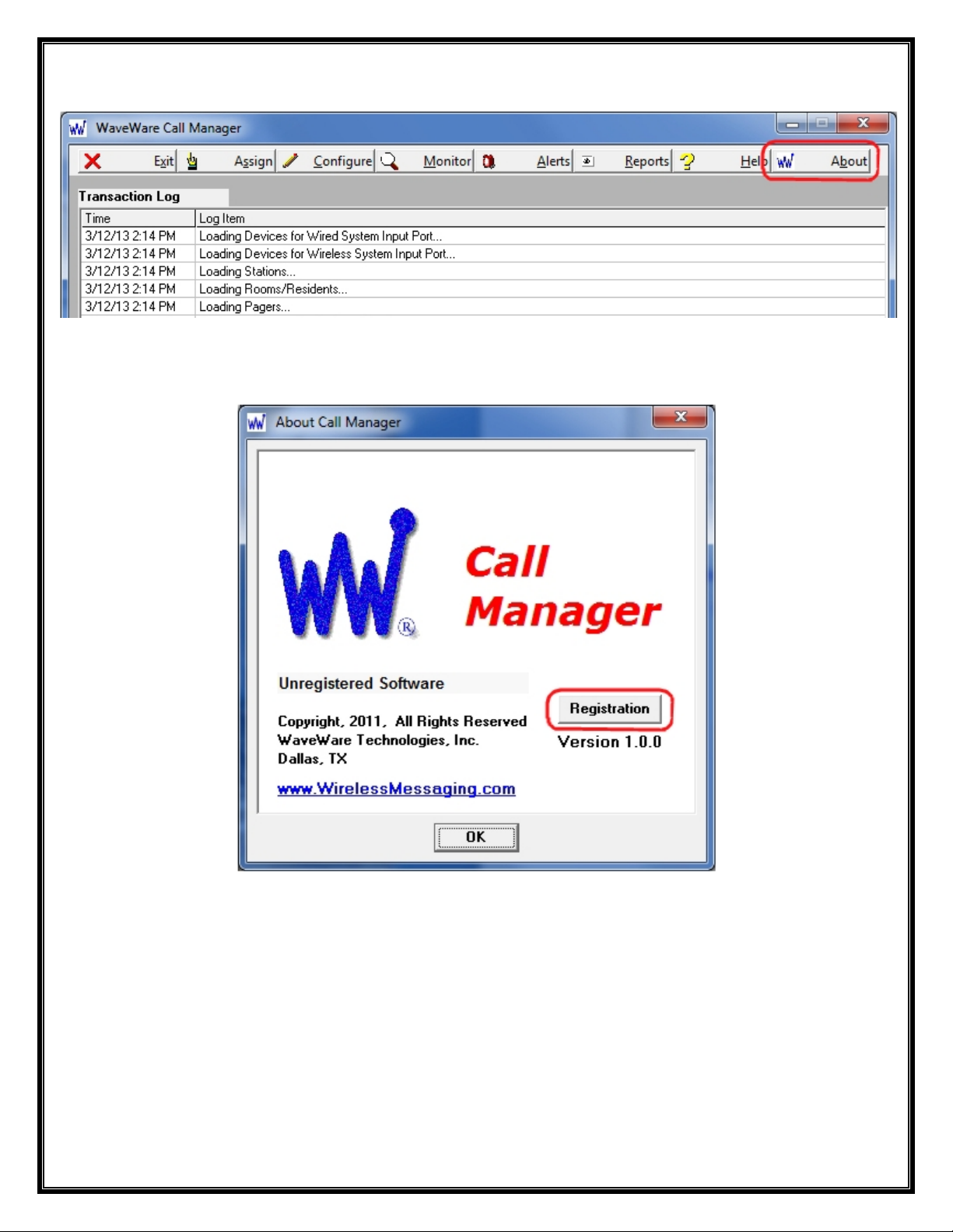
On the main “Call Manager Software” Screen, Click on the “About” Button, as Shown below. See Fig. 5
Fig. 5
Next, Click on the Registration Button. See Fig.6
Fig. 6
See next page for Instructions for Registering our Call Manager Software.
8
Page 9
Generating the “Request Key” for Call Manager
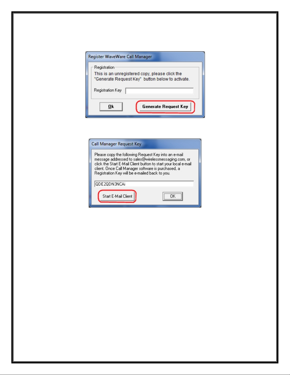
After Clicking the Register Icon or Registration Button, Click the “Generate Request Key” Button. See Fig. 7
Fig. 7
Follow the Instructions on the Request Key Screen to send the “Request Key” to WaveWare. See Fig. 8
Fig. 8
If you have Internet and Email capability on this PC, Click on the “Start E-Mail Client” Button. See Fig. 8
IMPORTANT NOTE:
The “Activation Key” will ONLY work on the Computer that Generated the Request Key.
Please proceed to the Next Page for instructions to Send the Generated Request Key to Wav eWare.
9
Page 10
Email the “Request Key” for Call Manager to WaveWare
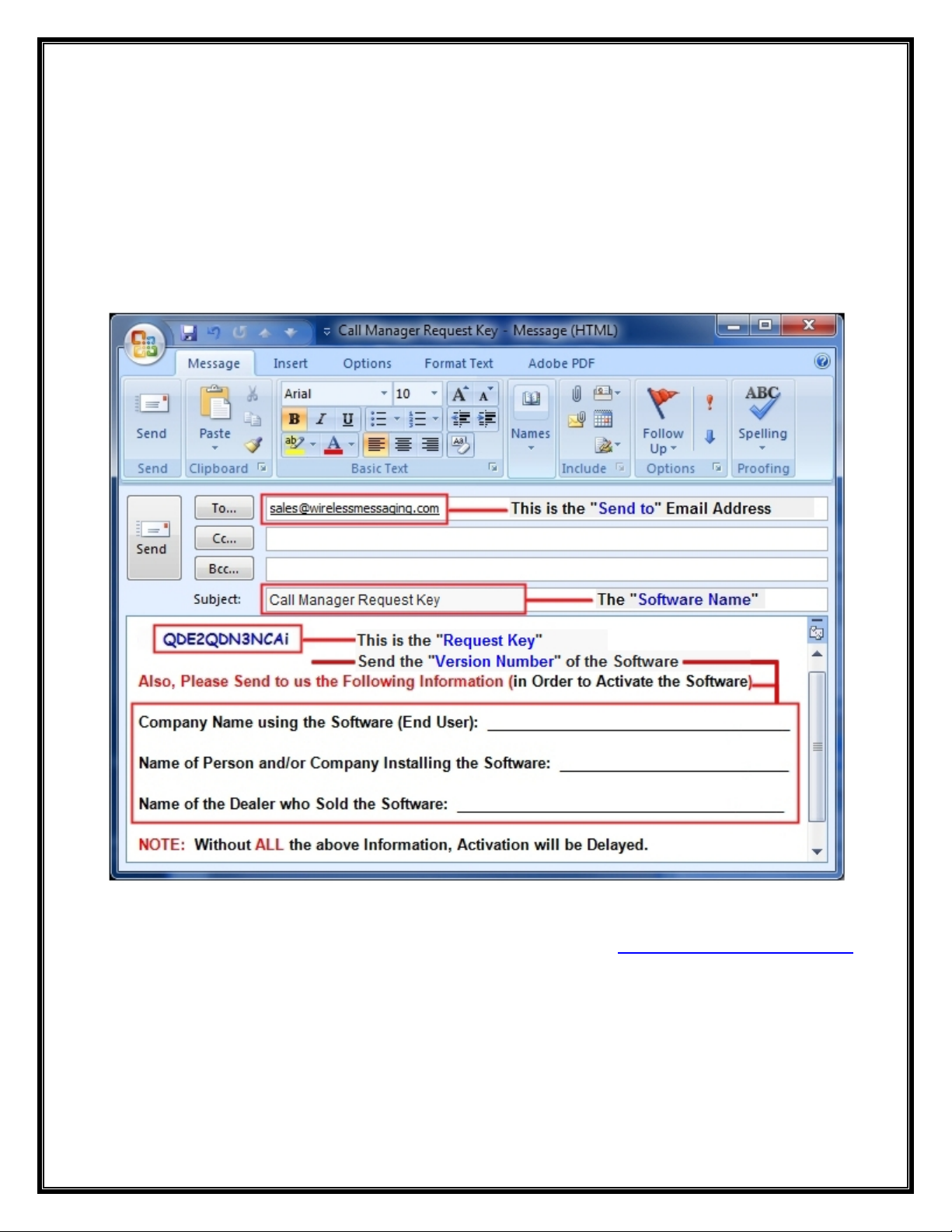
After you Click on the “Start Email Client” Button…(Fig. 8)
This should start and open an E-mail Client Window with the “Key” in the Body of the E-Mail, and our “Sales”
Email Address in the “To: Window” and “Software Name” in the Subject Line. As shown below in Fig. 9.
If you Do Not have Internet or Email on this Desktop PC, then Copy and Paste the Request Key into Notepad or a
Word Document and then Copy that file to a Flash Drive and take to a PC that does have Email capability.
We cannot do the Activation over the Phone.
Please, be sure to “ADD ALL” of the 4 Required Information Fields to the Email, as shown below. See Fig. 9
Fig. 9
NOTE 1: Include in the Body of the E-Mail: Your Company Name, Contact Name and the Name of the Dealer from
whom the “Software was Purchased From” and send the E-Mail to us: Sales@WirelessMessaging.com
Include the Version of the Software you are installing.
NOTE 2: Failure to Send All the Required Information will Delay sending the Activation Key. See Fig. 9
Without All the Required Information, No Key will be sent.
10
Page 11
Registering/Activating Call Manager
WaveWare will send a Reply Email with the “Registration/Activation Key” for either a Trail Key or Permanent Key.
If you have not Received a Reply within 30 minutes, please call us at: 1.800.373.1466, and ask for Tech Support.
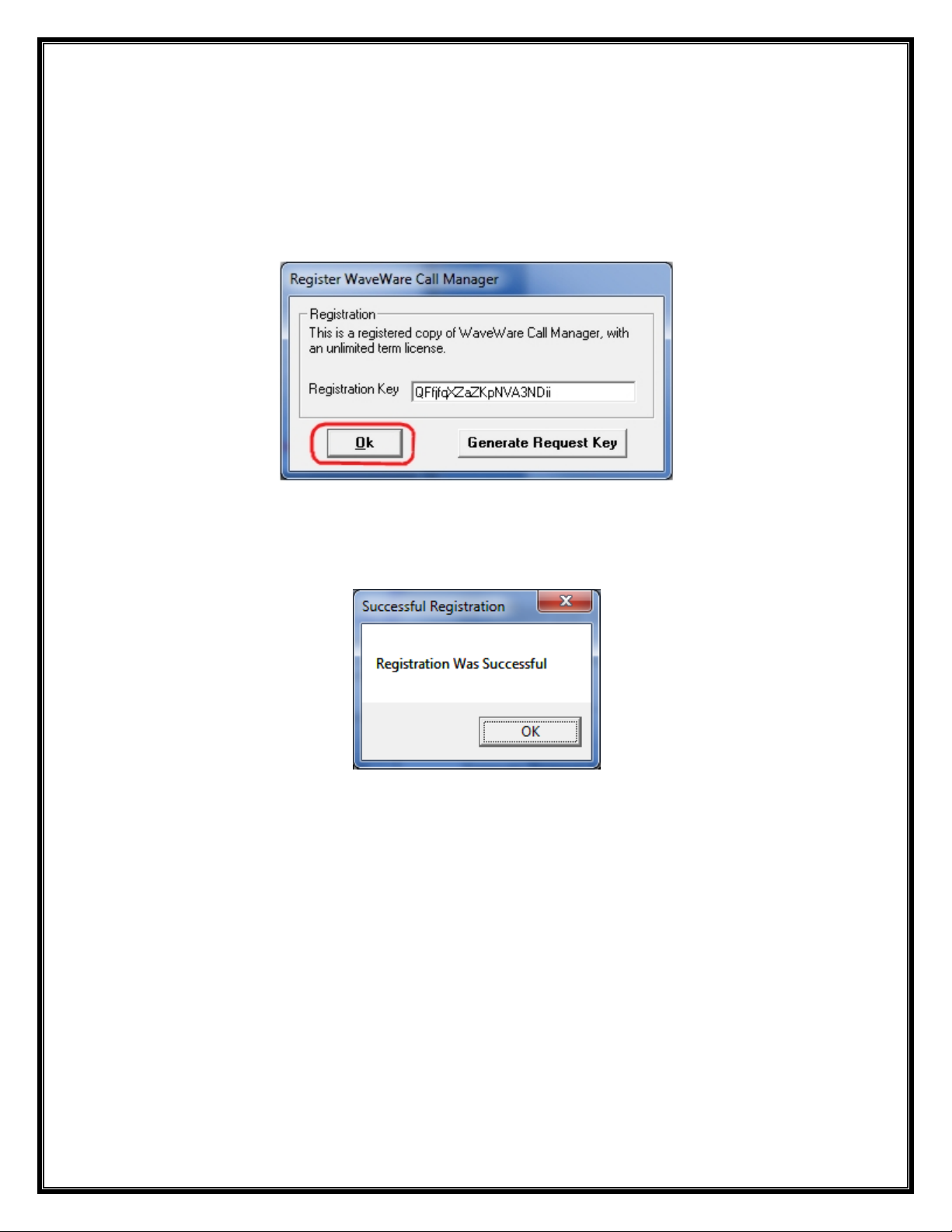
Copy and Paste the “Activation Key” into the “Registration Key” Field and Click “OK”. See Fig. 10
Fig. 10
You should then see: “Registration Was Successful”. Click “OK”, See Fig. 11
Fig. 11
This Concludes the Registration Process.
If you have any Problems with the Installation or Registration or just have Questions, please Contact the Dealer
from whom you have Purchased the Software.
Please Note:
WaveWare Supports our Dealers and our Dealers Support their Customers.
Thank you.
Next: How to Configure Call Manager Software
11
Page 12

WaveWare Technologies, Inc.
“We Deliver Information at the Speed of Light”
Call Manager Software
Configuring the Call Manager Software
NOTE: This Software Must be “Running” in order to work. So Please Only “Minimize”, Do Not Close or Exit Out of
the Software after you have Finished with the Setup and Configuration.
You should see a Blinking Blue WW Logo in the Bottom Right Corner of your Desktop, possibly under
“Hidden Icons” to Confirm that the Software is Running.
To get Started, Click on the “Configure” Button to start the Configuration Process, as Shown below. See Fig. 13
Fig. 13
You will be asked if you are sure, as the System is “Disabled” During the Configuration Process. See Fig. 14
Fig. 14 Click Yes.
NOTE:
The Call Manager “Configuration Screen” has “15 Steps” that will need to be “Configured/Defined” in order for
the Software to work Properly with the Pagers, Transmitters and Repeater(s), as well as other Wired and Wireless
Devices, depending of the Application Requirements.
12
Page 13

STEP 1 – Configure Inovonics Input Com Port
Click on the “Configure Input COM Port” Button as shown in Step 1. See Fig. 15
Fig. 15
Choose the Com Port Number and Setting for that Com Port and Click “OK”. See Fig. 16
Fig. 16
Step 2 is Next.
13
Page 14
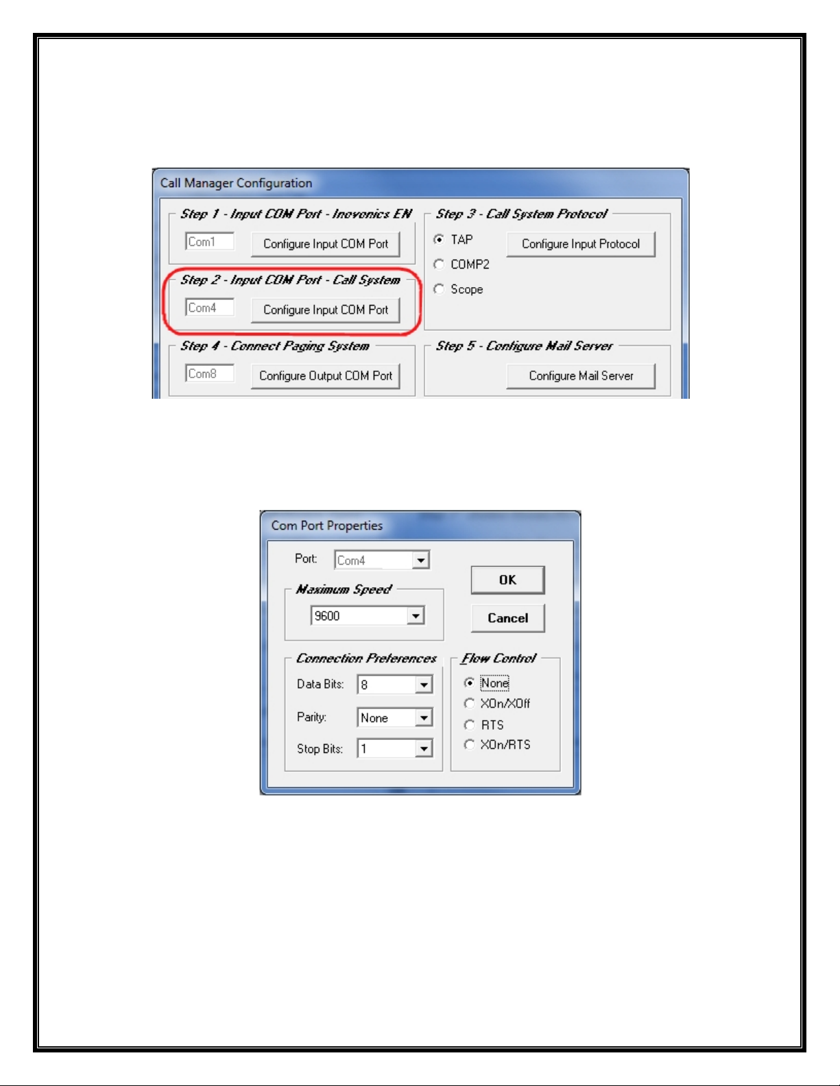
STEP 2 – Configure Input Com Port – Wired Call System
Click on the “Configure Input COM Port” Button as shown in Step 2. See Fig. 17
Fig. 17
Choose the Com Port Number and Setting for that Com Port and Click “OK”. See Fig. 18
Fig. 18
Step 3 is Next.
14
Page 15
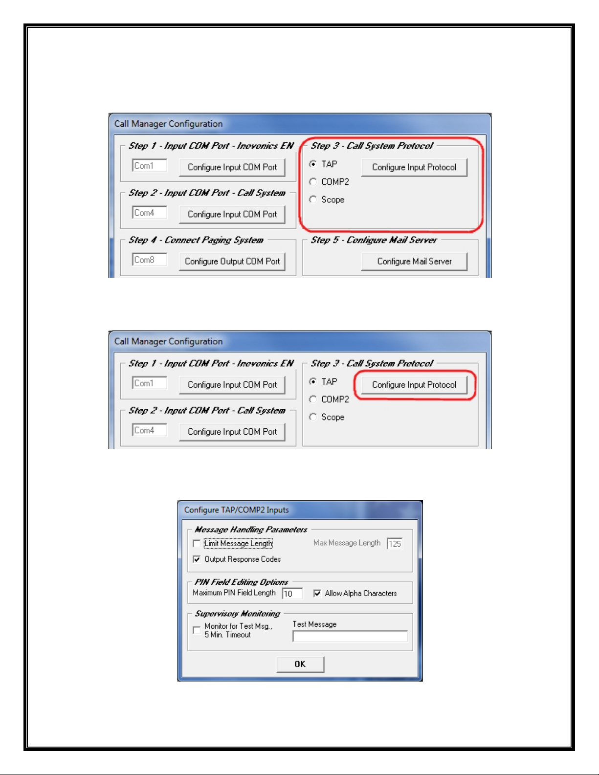
STEP 3 – Configure Input Protocol – Wired Call System
Click on the “Protocol” Option to be used as shown in Step 3. See Fig. 19
Choices are: TAP, COMP2 and Scope Protocols.
Fig. 19
Click on the “Configure Input COM Port” Button as shown in Step 3. See Fig. 20
Fig. 20
Configure the TAP / COMP2 Inputs, Default settings are shown below. Click “OK” when Finished. See Fig.21
Fig. 21
Step 4 is Next.
15
Page 16

STEP 4 – Configure Output Com Port – Connect Paging System
Click on the “Configure Output COM Port” Button as shown in Step 4. See Fig. 22
Fig. 22
Choose the Com Port Number and Setting for that Com Port and Click “OK”. See Fig. 23
Fig. 23
Step 5 is Next.
16
Page 17

STEP 5 – Configure E-Mail Server
Click on the “Configure Mail Server” Button as shown in Step 5. See Fig. 24
Fig. 24
See Next Page for the Mail Server Configuration Information
Step 5 is Continued…Next Page.
17
Page 18

Configure E-Mail Server – Continued
In this Tab, you would enter the “Mail Service’s Information” (SMTP) that you will be using.
You may need to obtain this Information from the IT Dept.
Configure similar as shown in the Example below.
You can Include Email Recipients in your Message Recipients List in addition to Pager Recipients.
See Step 6 (Page 19).
If Authentication is Required, Fill in the User ID and Password.
To Test the Setup, Enter the “To Address:” and Click the “Test Mail Server” Button.
You should then see one of these Screens shown below:
If you see this Screen, please recheck your
Information and configuration and try again.
If you see this Screen, the Configuration is
Correct and you are ready for the next Step.
Step 6 is Next.
18
Page 19

STEP 6 – Define Message Recipients
Click on the “Define Msg Recipients” Button as shown in Step 6. See Fig. 25
Fig. 25
Click on the “ADD” Button to start adding the Pagers used with this Sy stem. See Fig. 25A
Fig. 25A
19
Page 20

Define Message Recipients - Continued
Add a “Name” Associated with the “Pager ID” you want to use. See Fig. 26
Or
Add an “ID Number” Associated with the “Pager ID” you want to use. See Fig. 27
Or
Add a “Name” Associated with the “Email Address” you want to use. See Fig. 28
Fig. 26 Fig. 27 Fig. 28
When Finished, Click “End”.
The “Define Message Recipients” Screen will List all Names and Pager ID’s and Email Addresses. See Fig. 28A
Fig. 28A
In the Above Screen you may Test the Pagers. Highlight the Recipient and Click the “Test” Button.
You may also “Edit” existing Names/Addresses or “Delete” them in the above Screen. See Fig. 28A
When Finished, Click “Exit”.
Step 7 is Next.
20
Page 21

STEP 7 – Define Call Device Types
Click on the “Define Call Device Types” Button as shown in Step 7. See Fig. 29
Fig. 29
You will see a List of “Pre-Entered” Devices some of which are “Hard-Coded” and should Not be “Deleted”.
The Hard-Coded Device Types are: Pendant, Call Cord, Pull Cord, Door and Window.
To Add other Device Types, Click on the “Add” Button. See Fig. 30
Enter the “Name” of the Additional Device Type and Click “Add”. See Fig. 31
You will see the New Device added to the List. See Fig. 32
Fig. 30
Fig. 31
When Finished, Click “End” and “Exit”.
Step 8 is Next
21
Fig. 32
Page 22

STEP 8 – Define Rooms / Residents
Click on the “Define Rooms / Residents” Button as shown in Step 8. See Fig. 33
Fig. 33
Click on the “ADD” Button to start Assigning Rooms to Residents. See Fig. 34
Fig. 34
22
Page 23

Define Rooms / Residents - Continued
Add a “Room Number” and the “Resident” Name Associated with the Room. See Fig. 35
Or
Add a “Room Number” and leave the “Resident” Field Blank. See Fig. 36
Fig. 35
The “Define Rooms / Residents” Screen should show all the Added Room Numbers and Residents. See Fig. 37
Fig. 36
When Finished, Click “End”.
Fig. 37
You may also “Edit” existing Rooms/Residents or “Delete” them in the above Screen. See Fig. 37
When Finished, Click “Exit”.
Step 9 is Next.
23
Page 24

STEP 9 – Register Call Devices
Click on the “Register Call Devices” Button, as shown in Step 9. See Fig. 38
Fig. 38
Choose the “Wired Call System Input Port”. See Fig. 39 on Page 25
OR
Choose the “Inovonics Wireless System Input Port”. See Fig. 40 on Page 26 thru 28
24
Page 25

STEP 9 – Register Call Devices – Wired Call Systems
Configuring the “Wired Call System Input Port”
Configuration for use as a Wired Call Device - “Contact Closure” Device
Choose the “Wired System Input Port”. See Fig. 39-1 “B”
To “Register Call Devices” simply “Trigger” the Device and wait until you see it on the Screen. See Fig. 39-1 “A”
NOTE: Trigger one Device at a time and wait a Few Moments until the System “Acknowledges” the Device.
Fig. 39-1
In this Example the Device is being used with a Contact Medical Device.
When the Resident Pushes the Call Button on the Call Cord, the Device is
Triggered and will send out a Signal to the Call Manager Software which sends a
Alert Message out to the Assigned Recipient (Pager or Email Address).
Fig. A:
Trigger the Wired Call
Device and wait a Few
Moments.
The New Device should be
Displayed on the Screen.
After the Device is Shown,
you can Choose:
-The “Device Type”
-The “Room”
Do this for Every Device
Type Registered.
Note: You can Assign the
Room at a Later time, if you
wish.
Fig. B:
Choose One:
-Call System Input Port
-Inovonics EN Wireless
System Input Port
Here in this Example we are
Working with the Call
System Input Port to
Register Wired Call Devices.
This Device Type is a Call
Cord, which Normally works
with a Contact Device.
You can also Assign an
“Installer” Pager, to be used
for Testing during this Time.
25
Page 26

STEP 9 – Register Call Devices – Wireless Inovonics
Configuring the “Inovonics Wireless System Input Port”
Configuration for use as a Wireless Transmitter - “Pendant” Device
Choose the “Inovonics EN Wireless System Input Port”. See Fig. 40-1 “B”
To “Register Call Devices” simply “Trigger” the Device and wait until you see it on the Screen. See Fig. 40-1 “A”
NOTE: Trigger one Device at a time and wait a Few Moments until the System “Acknowledges” the Device.
Fig. 40-1
In this Example the Device is a “Wireless Pendant”.
This Device is Triggered/Activated when the Button on the Pendant is Pressed.
This Device sends a Signal to the Central Receiver which is attached to the
Call Manager Software. The Call Manager Software sends an Alert Message out
to the Assigned Message Recipient (Pager).
Fig. A:
Trigger the Wireless Call
Device and wait a Few
Moments.
The New Device should be
Displayed on the Screen.
After the Device is Shown, you
can Choose:
-The “Device Type”
-The “Room”
Do this for Every Device Type
Registered.
Note: You can Assign the
Room at a Later time, if you
wish.
Fig. B:
Choose One:
-Call System Input Port
-Inovonics EN Wireless System
Input Port
Here in this Example we are
Working with the Inovonics
Wireless System Input Port to
Register Wireless Call Devices.
Fig. C:
Choose Call Processing:
In this Example this Area is
Grayed Out because the
“Pendant” is the Device Type.
These Fields are for
Configuration of “Universal
Transmitters” Only.
You can also Assign an
“Installer” Pager, to be used for
Testing during this Time.
26
Page 27

STEP 9 – Register Call Devices – Wireless Inovonics
Configuring the “Inovonics Wireless System Input Port”
Configured for use as a Universal Transmitter - “Terminal” Device (Ex: Contact Closure)
Choose the “Inovonics EN Wireless System Input Port”. See Fig. 40-2 “B”
To “Register Call Devices” simply “Trigger” the Device and wait until you see it on the Screen. See Fig. 40-2 “A”
NOTE: Trigger one Device at a time and wait a Few Moments until the System “Acknowledges” the Device.
Fig. 40-2
In this Example the Device is being used with a Contact Medical Device.
This model Universal Transmitter only has a “Terminal” Block, so when the
Device is Triggered and Reset, the Device will send out a Signal to the Central
Receiver which is attached to the Call Manager Software. The Call Manager
Software sends an Alert Message out to the Assigned Msg Recipient (Pager).
Fig. A:
Trigger the Wireless Call
Device and wait a Few
Moments.
The New Device should be
Displayed on the Screen.
After the Device is Shown, you
can Choose:
-The “Device Type”
-The “Room”
Do this for Every Device Type
Registered.
Note: You can Assign the
Room at a Later time, if you
wish.
Fig. B:
Choose One:
-Call System Input Port
-Inovonics EN Wireless System
Input Port
Here in this Example we are
Working with the Inovonics
Wireless System Input Port to
Register Wireless Call Devices.
Fig. C:
Choose Call Processing:
In this Example the Universal
Transmitter is used as a
Contact Closure.
For this Purpose the Call
Processing should be set to
“Terminal” for Both Initiation
and Cancelation.
You can also Assign an
“Installer” Pager, to be used for
Testing during this Time.
27
Page 28

STEP 9 – Register Call Devices – Wireless Inovonics
Configuring the “Inovonics Wireless System Input Port”
Configured for use as a Universal Transmitter - “Magnet” Device (Ex: Doors or Windows)
Choose the “Inovonics EN Wireless System Input Port”. See Fig. 40-3 “B”
To “Register Call Devices” simply “Trigger” the Device and wait until you see it on the Screen. See Fig. 40-3 “A”
NOTE: Trigger one Device at a time and wait a Few Moments until the System “Acknowledges” the Device.
Fig. 40-3
In this Example the Device is being used with a Door.
This model Universal Transmitter comes with a Magnet, so when the Door is
Open and Closed, the Device sends out a Signal to the Central Receiver which
is attached to the Call Manager Software. The Call Manager Software sends an
Alert Message out to the Assigned Message Recipient (Pager).
Fig. A:
Trigger the Wireless Call
Device and wait a Few
Moments.
The New Device should be
Displayed on the Screen.
After the Device is Shown, you
can Choose:
-The “Device Type”
-The “Room”
Do this for Every Device Type
Registered.
Note: You can Assign the
Room at a Later time, if you
wish.
Fig. B:
Choose One:
-Call System Input Port
-Inovonics EN Wireless System
Input Port
Here in this Example we are
Working with the Inovonics
Wireless System Input Port to
Register Wireless Call Devices.
Fig. C:
Choose Call Processing:
In this Example the Universal
Transmitter is used for a
“Door” Monitor.
For this Purpose the Call
Processing should be set to
“Magnet” for Both Initiation
and Cancelation. Or the
Cancelation could be set to
None.
You can also Assign an
“Installer” Pager, to be used
for Testing during this Time.
28
Page 29

STEP 10 – Register Receivers
Click on the “Register Receivers” Button as shown in Step 9. See Fig. 41
Fig. 41
In this Step, you are Registering Inovonics Receivers, so that you can use them to help Identify the Closest
Receiver Location to the Alert Call Device by Comparing the Signal Strength.
Chose the “Site Survey Device” you wish to use to Perform this Survey with. See Fig. 42
You should find the Serial Number of the Device (via a Labeled on the Device) that matches in the Dropdo wn List.
You can also see the same Devices on Page 24 (Step 9): “Register Call Devices”, under the Inovonics “Wireless
System Input Port” Section.
After Choosing the Device to use for the Site Survey, simply “Trigger” the device and All the Pre “Registered
Receivers” in Range will be Displayed and show their Signal Strength (Margin).
You should Name the Receiver by Clicking on the Name Field. See Fig. 43
Fig. 42
Fig. 43
You can Delete a Receiver by Highlighting the Name and Clicking the “Delete” Button. Click “OK” when Finished.
Step 11 is Next.
29
Page 30

STEP 11 – Define Stations
Click on the “Define Stations” Button, as shown in Step 10. See Fig. 44
Fig. 44
In this Step, you will Define Stations for Purposes of Assigning Message Recipients (Pagers) and Rooms to the
Stations and for Reporting Call History by Station.
You will see an “Example Station” Listed which can be either “Edited” or “Deleted”. See Fig. 45
To Add other “Stations”, Click on the “Add” Button. See Fig. 45
Enter the “Name” of the Additional “Station” and Click “Add”. See Fig. 46
You will see the New Station(s) added to the List. See Fig. 47
Fig. 45
Fig. 46
When Finished, Click “End” and “Exit”.
Step 12 is Next.
30
Fig. 47
Page 31
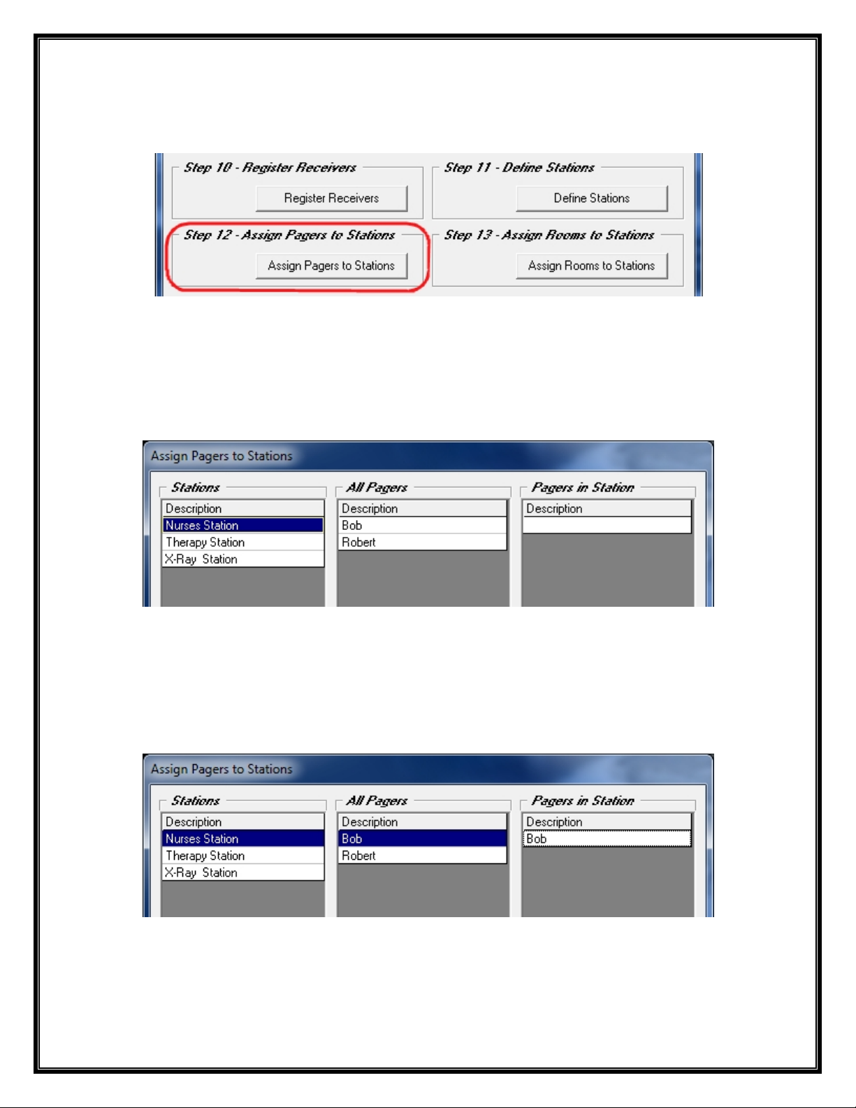
STEP 12 – Assign Pagers to Stations
Click on the “Assign Pagers to Stations” Button, as shown in Step 11. See Fig. 48
Fig. 48
In this Step, you are Associating Pagers to Stations, so that when a Call Event occurs for a Particular Room, only
the Pagers Assigned to the Station Responsible for that Room will be Paged.
The “Stations” List should be Populated with the Stations Previously Setup in Step 11 (Page 30).
The “All Pagers” List should be Populated with the Recipients Previously Setup in Step 6 (Page 19).
See Fig. 49
Fig. 49
Add a Pager to a Station
Highlight the “Station” Name and Click on a Pager in the “All Pagers” List to add it to the “Station List”.
The Pager will be shown on the “Pagers in Station” List.
Use this same Method to “Remove” a Pager from the Station List.
See Fig. 50
Fig. 50
Click “OK” When Finished.
Step 13 is Next
31
Page 32

STEP 13 – Assign Rooms to Stations
Click on the “Assign Rooms to Stations” Button, as shown in Step 12. See Fig. 51
Fig. 51
In this Step, Rooms are “Assigned” to Stations.
When a Call Event for a Room is “Triggered” a Message is sent to the Recipients (Pagers) that are “Assigned” to
that Station. This Information is also used in the Call Event Reports.
The “Stations” List should be Populated with the Stations Previously Setup in Step 11 (Page 30).
The “All Rooms” List should be Populated with the “Rooms/Residents” Previously Setup in Step 8 (Page 22).
See Fig. 52
Fig. 52
Add a Room to a Station
Highlight the “Station” Name and Click on a Room in the “All Rooms” List to add it to the “Rooms in Station”.
The Room will be shown on the “Rooms in Station” List.
Use this same Method to “Remove” a Room from the Station List.
See Fig. 53
Fig. 53
Click “OK” When Finished.
Step 14 is Next
32
Page 33

STEP 14 – Schedule Reports – Report Templates
** NOTE **
Before you can continue to Step 14 you need to First Create a Report Template.
On the Main Screen, Click on the “Reports” Button in the Menu Bar.
For Detailed Report Configuration Options and Creating and Saving a Template:
Please see Page 41.
Schedule the Report and Assign a Template (Step 14): See Next Page…
34
Page 34

STEP 14 – Schedule Reports
Assign Template to an Email Recipient
After Creating and Saving a Report Template you can now Schedule Reports.
This Feature is for the Ability to Send a Scheduled Report to an Email Address Recipient.
Click on the “Config Schedule Reports” Button, as shown in Step 14.
Highlight a Template and Choose an Email Recipient as shown below.
You can have the same Template sent to more than one Email Recipient.
Example: “Template 1” is Assigned to the Email Address “Bobby” which was previously Configured in
Step 6 (Page 19).
Adjust the “Output Time” for the Email to be sent. You can also do a “Test” from this Screen.
Click “OK” when Done.
Step 15 is Next
35
Page 35

STEP 15 – General Settings
Click on the “Configure General Settings” Button, as shown in Step 13. See Fig. 54
Fig. 54
The General Configuration Screen is Divided into 5 Sections: “Shift Start Times”, “Report Threshold Values”,
“Call Notification Settings”, “Call system Settings” and “General”, as Shown below. See Fig. 55
Fig. 55
The Following Page will address each Individual Section.
36
Page 36

Shift Start Times: Adjust the Shift Times to Match your Requirements. See Fig. 56
The Purpose of Shift Start Times is to Allow the Call Event Reports to Include Shift Related Information.
Fig. 56
Report Threshold Values: Adjust the Values for Frequent Call Threshold and Slow Response Threshold.
The Purpose of the Frequent Call Threshold is to allow the Reporting System to Identify rooms that Generate Frequent Calls.
The Slow Response Threshold allows the Reporting System to Highlight Slow Response Times.
Printed Report Footer: This Field is Editable - Allows the User to Display their Company Information at the Bottom of each
Printed Report Page. See Fig. 57
Fig. 57
Call Notification Settings: Choose the Number of “Repeats” before the system starts the Escalation Processing and the
Number of “Seconds” between each Repeat. Choose from the Pager List which Pager you wish to use for the “Supervisor”
Pager and “Maintenance” Pager.
Call Notifications Continue until the Call is “Canceled”. Escalated Calls go to “Supervisor” Pager.
Low Battery and Tamper Alerts go to the “Maintenance” Pager.
Option: To “Output to an Adaptive LED Sign”. Check Box and Click on the “Configure LED Sign Output”.
Option: For hearing an “Asterisk” Sound on Errors. See Fig. 58
Fig. 58
General: You may choose to be “Prompted” for a “Configurable” Password for “ALL” Functions:
Admin has Access to All Areas, where the User can ONLY Access the “Assign” Button in the Menu Bar.
Option: To be “Warned” for “Unregistered” Devices appearing on the Log Screen.
Option: To Hear an “Exclamation” Sound on Alarms when Viewing the Alerts Screen.
See Fig. 59
Fig. 59
Page 37

WaveWare Technologies, Inc.
Click on the “Monitor” Button to Open the Monitor Window, as Shown below. See Fig. 60
“We Deliver Information at the Speed of Light”
Call Manager Software
Call Manager Software: Monitoring
Fig. 60
In the Monitor Window you can View all Serial Port Activity. See Fig. 61
Fig. 61
NOTE: For more Detailed Logging, Click on the “Verbose Logging” Checkbox. See Fig. 61
Alerts Window is Next
38
Page 38

WaveWare Technologies, Inc.
Click on the “Alerts” Button, to Open the Active Alerts Window. See Fig. 62
“We Deliver Information at the Speed of Light”
Call Manager Software
Call Manager Software: Alerts Window
Fig. 62
The Window below shows the “Active Alerts”. A Single “Audible Alarm Sound” will be heard for Each Alert.
Alerts will “Disappear” from this Screen as they are “Reset” by the Staff. See Fig. 63
Fig. 63
Page 39

The Alerts can be “Canceled” by Highlighting the “Line” of the Active Alarm and Click the “Cancel” Button.
See Fig. 64
Fig. 64
“Maintenance Alerts” will need to be “Acknowledged” in order to “Cancel” the Alert. See Fig. belo w…
Page 40

WaveWare Technologies, Inc.
“We Deliver Information at the Speed of Light”
Call Manager Software: Report Generator - Create and Save Templates
Click on the “Reports” Button, to View the Reports Configuration Screen, as Sho wn below. See Fig. 66
Call Manager Software
Fig. 66
The Main Reports Screen offers a Variety of Choices for Configuring Specialized Reports. See Pages: 42-43
After Configuring the Report Template, Click the “Save as Template” Button. See Page 43 For more Information.
For Scheduling Reports to be “Emailed” to a Recipient, See Step 14 (Page 35).
Fig. 67
41
Page 41

Report Type
Response Times: Sort By: Choices of Date, Hour, Room, Station or Call Volume. See Fig. 68
Fig. 68
Activity Listing: Sort By: “Time of Day” or “Response Time”.
Filtered By: Choices of “All Stations and Rooms” or choose “Room” or “Station”. See Fig. 69
Fig. 69
Frequent Calls: No Sort or Filter, but Choice of Month and Date. See Fig. 70 and 70A
Fig. 70
42
Fig. 70A
Page 42
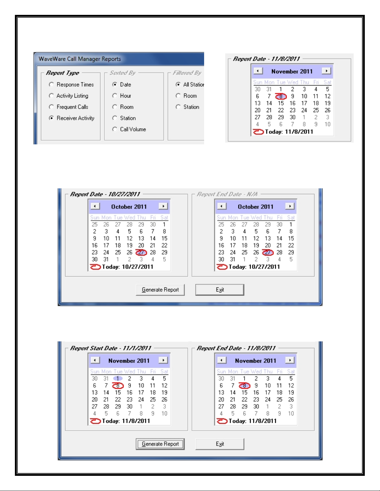
Report Type - Continued
Receiver Activity: No Sort or Filter, but Choice of Month and Date. See Fig. 71A and 71B
Fig. 71A
Fig. 71B
Report Date
When a Report for a “Particular Date” is Required: Only the Left Side Calendar is Highlighted and Available.
You may go back to a Previous Time and choose the Month and Day. See Fig. 72
Fig. 72
When a Report for a “Range of Dates” is Required: Both the Left and Right Calendars become Available.
You may start “Back in Time” to “Present Day” and choose the “Month and Day” for Start and End Times.
See Fig. 73
Fig. 73
Page 43

When All Choices are made and the Template is Complete, Click the “Save as Template” Button.
Saving and Naming the Template
Enter a “Template Name” (Ex: Template 3) and Click “OK” to Save the Template.
The “Saved” Template will be Shown List under “Current Templates” next time you Open this Window.
Deleting a Template
For any old Templates that are no longer used, you can Place Check Mark next the Template Name and Click on
the “Delete Checked Templates” Button.
Page 44

Generating a Report
When All Choices are made and you are ready to Create the Report, Click on the “Generate Report” Button.
See Fig. 74
Fig. 74
Below is the Generated Report Screen, Click on the “Print” Button for a Paper Copy. See Fig. 75
Fig. 75
Assign Window is Next
44
Page 45

WaveWare Technologies, Inc.
Click on the “Assign” Button to View the Assign Wireless Call Devices Screen
“We Deliver Information at the Speed of Light”
Call Manager Software
Call Manager Software: Assign Window
For Wireless Call Devices
This Feature is to allow a “User” the Ability to “Assign” and to “Un-Assign” or “Re-Assign” a Room to a Call
Device, without the need of having Access to the Main Configuration Scre ens.
This Protects the System from becoming Corrupt by an Accidental Change to Important Settings/Configurations.
NOTE: You Must use the Password Feature in General Settings Step 14 (Page 37) for this to be Effective.
You Do Not have to use Passwords, but it is Strongly Suggested that you do so.
Assign Window Continues on Next Page…
45
Page 46

Assign Window - Continued
For Wireless Call Devices
In this Screen, you have the Ability to Change the Room Assignment.
You may “Un-Assign” or “Re-Assign” the Call Device to another Room Number / Resident.
Click on the “Room” Field and use the Drop down List to choose a “Room Number / Resident”.
Rooms and Residents are Configured in Step 8 (Page 22).
If you leave a Room “Un-Assigned” you get this Warning Window. It is just a “Reminder”, you can Click “OK”.
NOTE:
To Add a New Pendant or other Call Device, you would need to go to Step 9, in the Main Configuration Screens.
See Page 24
Troubleshooting Error Messages is Next…
46
Page 47
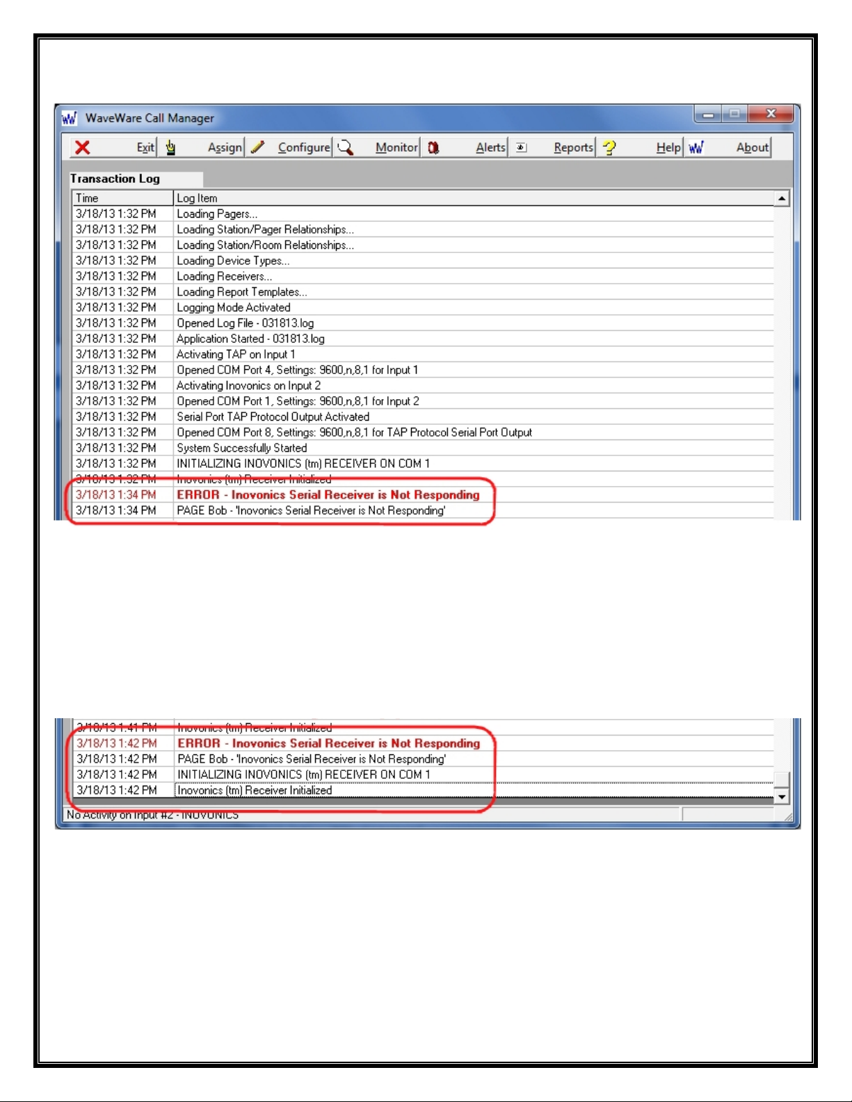
Troubleshooting – Inovonics Central Receiver
Error Message – “ERROR – Error Initializing Inovonics Receiver” Occurs when:
1- The Central Receiver has Lost Power (Unplugged from Outlet or UPS Failure)
2- The Central Receiver’s Serial Connection has been Lost (Disconnected or Wrong Com Port Assignment)
The System will send out an Alert Message to the “Maintenance” Pager.
After Power or the Serial Connection has been “Restored”, you will see the Log: “Inovonics Receiver Initialized”.
47
Page 48

Troubleshooting – Paging System
Error Message – “ERROR – Error Logging Into Paging System, Message Discarded” Occur s when:
1- The Paging System has Lost Power (Unplugged from Outlet or UPS Failure)
2- The Paging System’s Serial Connection has been Lost (Disconnected or Wrong Com Port Assignment)
Since the Paging System is having an issue, the System is “Not” able to send out an Alert Message.
After Power or Serial Connection has been “Restored”, you can Test the System by Going to Step 6 (Page 19).
Highlight a “Recipient” that has been “Assigned to a Pager” and Click the “Test” Button, or “Trigger” an Al ert.
48
Page 49

Troubleshooting – Tamper Alert
Alert Message – “Tamper Alert – 503 – Janet Call Cord” is Stating that Room 503 has a Problem with the Call Cord and should
be Check. The System will Page the “Message Recipient” Associated with this Room and the Pager Assign to “Maintenance”.
This Same Alert Message will be shown in the Alerts Screen under Maintenance Alerts, (See Page 40).
When Maintenance Alerts are “Acknowledged” to be “Removed” from the “Active Alerts Screen”, the “Acknowledgement” is
shown in the “Transaction Log” as shown above.
Page 50

This Ends the Call Manager Manual
Please Contact your “Software Dealer” for Assistance or Questions.
WaveWare Technologies, Inc. 1.800.373.1466 Support@WirelessMessaging.com Web: www.WirelessMessaging.com
Call Manager Software: Developed by WaveWare Technologies, Inc.
Copyright © 2013
 Loading...