

Page 1

API-8/232
INSTALLATION / OPERATION MANUAL
Page 2

Page 3

MONITOR TECHNOLOGIES INC.
Installation of this product in accordance with this manual, applicable codes, and the instructions of the
Authority Having Jurisdiction is mandatory.
Monitor Technologies Inc. shall not under any circumstances be liable for any incidental or consequential
damages arising from loss of property or other damages or losses owing to the failure of Monitor
Technologies products beyond the cost of repair or replacement of any defective products.
Monitor Technologies Inc. reserves the right to make product improvements and change product
specifications at any time.
The contents of this manual and the related software program are proprietary in nature and are intended
solely for the distribution to authorized persons, companies, distributors, and/or others for the sole purpose
of conducting business associated with Monitor Technologies Inc. The distribution of information
contained with this manual to unauthorized persons shall constitute a violation of any distributor agreements
and may require the implementation of legal proceedings.
While every precaution was taken during the preparation of this manual to ensure the accuracy of its
contents, Monitor Technologies Inc. assumes no responsibility for errors or omissions.
I
Page 4

FCC/IC NOTICES
NOTICE:
(1) This equipment complies with Part 68 of the FCC rules. Imprinted on the component side of the printed circuit board
(model SAMI-API) is a label that contains, among other information, the FCC registration number and the Ringer
Equivalence Number (REN) for this equipment. If requested this information must be provided to the telephone
company.
(2) This equipment is supplied with two PCB mounted female RJ11 Jacks and a five foot male to male RJ11 line set cord.
(3) The REN is used to determine the quantity of devices which may be connected to the telephone line. Excessive Ren’s
on the telephone line may result in the devices not ringing in response to an incoming call. In most, but not all areas, the
sum of the Ren’s should not exceed five (5.0). To be certain of the number of devices that may be connected to the line,
as determined by the total Ren’s contact the telephone company to determine the maximum REN for the calling area.
(4) If the terminal equipment (model SAMI-API) causes harm to the telephone network, the telephone company will notify
you in advance that temporary discontinuance of the service may be required. If advance notice is not practical, the
telephone company will notify the customer as soon as possible. Also, you will be advised of your right to file a
complaint with the FCC if you believe it is necessary.
(5) The telephone company may make changes in it’s facilities, equipment, pertains, or procedures that could affect the
operation of this equipment. If this happens, the telephone company will provide advance notice in order for you to
make the necessary modifications in order to maintain uninterrupted service.
(6) If trouble is experienced with this equipment (model SAMI-API) please contact Monitor Technologies Inc. at 905-889-
6511 for repair and warranty information. If the trouble is causing harm to the telephone network, the telephone
company may request you remove the equipment from the network until the problem has been resolved.
(7) For repairs or service which can be performed by the customer please refer to the Trouble Shooting Section in Chapter 5
of this manual.
NOTICE: The Industry Canada label identifies certified equipment. This certification means that the equipment meets
telecommunications network protective, operational and safety requirements as prescribed in the appropriate Terminal
Equipment Technical Requirements document(s). The department does not guarantee the equipment will operate to the users
satisfaction.
Before installing this equipment, users should ensure that it is permissible to be connected to the facilities of the local
telecommunications company. The equipment must also be installed using an acceptable method of connection. The
customer should be aware that compliance with the above conditions may not prevent degradation of service in some
situations.
Repairs to certified equipment should be coordinated by a representative designated by the supplier. Any repairs or
alterations made by the user to this equipment, or equipment malfunctions, may give the telecommunications company cause
to request the user disconnect the equipment.
Users should ensure for their own protection that the electrical ground connections of the power utility, telephone lines and
internal metallic water pipe system, if present, are connected together. This precaution may be particularly important in rural
areas. Caution: Users should not attempt to make such connections themselves, but should contact the appropriate electric
inspection authority, or electrician, as appropriate.
NOTICE: The Ringer Equivalence Number (REN) assigned to each terminal device provides an indication of the maximum
number of terminals allowed to be connected to a telephone interface. The termination of an interface may consist of any
combination of devices subject only to the requirement that the sum of the Ringer Equivalence Numbers of all these devices
does not exceed 5.
ii.
Page 5

TABLE OF CONTENTS
CHAPTER 1 - INTRODUCTION
INTRODUCTION.............................................. 1-1
PURPOSE OF MANUAL.................................. 1-1
CHAPTER 2 - DESCRIPTION
INTRODUCTION.............................................. 2-1
DESCRIPTION.................................................. 2-1
COMPATIBILITY............................................... 2-1
SPECIFICATIONS............................................ 2-2
FEATURES....................................................... 2-4
CHAPTER 3 - INSTALLATION AND OPERATION
BOARD CONNECTIONS................................. 3-1 (DIA)
INSTALLATION INSTRUCTIONS……………… 3-2
PAGING SYSTEM CONNECTIONS…………….3-3
CHAPTER 4 - PROGRAMMING
SOFTWARE INSTALLATION.......................... 4-1
PROGRAMMING CONNECTIONS................... 4-1
PROGRAMMING INSTRUCTIONS................… 4-1
DIRECT TERMINAL CONNECTION…….4-2
REMOTE TERMINAL CONNECTION….. 4-3
DRY/WETTED OPTO INPUTS………….. 4-4
RS232 SERIAL INPUT……………………4-5
PROGRAMMING/DATA TRANSFER………….. 4-8
SAVING/OPENING DATA FILES………………. 4-9
CHAPTER - TROUBLESHOOTING AND SUPPORT
TROUBLESHOOTING……………………………5-1
LED STATUS INDICATORS……………………. 5-5
SUPPORT AND INFORMATION……………….. 5-6
Page 6

CHAPTER
1
INTRODUCTION
INTRODUCTION
The API-8/232 Pocket Pager Interface delivers custom message information to a paging
terminal for broadcast over standard radio paging architecture. The interface activates through
dry contact or wetted voltage openings and closings and/or pages data generated by a host
system that provides ASCII data event reporting via an RS-232 port (serial printer port).
PURPOSE OF THE MANUAL
This Manual provides descriptions and instructions for programming, installing and maintaining the
API-8/232 Pocket Paging Interface. A brief description of the remaining chapters is as follows.
• Chapter 2 - Description of functions and capabilities including specifications.
• Chapter 3 - Installation, Power Up, and External Connections.
• Chapter 4 - Programming
PAGE 1-1
Page 7

CHAPTER 2
DESCRIPTION
INTRODUCTION
This Chapter describes the characteristics, capabilities, features and specifications of the API-8/232 Pocket
Pager Interface.
DESCRIPTION
The API-8/232 is an eight input automated paging interface which interfaces with alarm and monitoring
equipment . The API-8/232 provides notification of alarm conditions to pagers from its’ 8 dry contact or
wetted voltage inputs. The interface links a facilities key equipment to a local, Customer Owned
Paging system via direct RS 232 connection or will connect to either a remotely located Customer
Owned Paging system or to a Wide Area paging terminal. When an alarm is triggered the unit sends a
full 80 character, pre-programmed alphanumeric message to a pager or group of pagers. Messages and
pager ID’s are programmed through the Windows 95/NTprogramming software.
API-8/232 is also equipped with an RS232 interface port to monitor an ASCII data string generated by a
host system (Fire Panel, Card Access System, Building Management Control System etc..). The
interface may be connected to a serial printer port and events that are directed to the port will be paged
to a user definable alphanumeric pager or group of pagers.
API-8/232 can be configured to send all data that appears on the host system serial port. Alternately, the
user can define, via the use of keywords or phrases that appear in the event strings, the type of events
that are to be paged and those to be ignored and discarded. Programming for the RS232 functions is
performed via the Windows 95/NT programming software.
Both the 8 opto-isolated inputs and the RS232 input port operate concurrently on the API-8/232
providing a high degree of flexibility in the choice of input sources and the ability of the product to
interface with most host systems.
Paging System Compatibility
The Pocket Pager Interface communicates with Paging Terminals via modem to modem Phone Line
Connection or via direct RS-232 connection .
Note: Where a Privately Owned Paging System provides telephone access for alphanumeric paging
(from a location remote to the terminal, encoder, transmitter, etc..) API-8/232 can be utilized to dial in
and deliver messages to the terminal via telephone lines and the TAP protocol. This eliminates the
need to place the API-8/232 within 50 feet of the paging terminal for a direct connection.
Direct Connect Paging System Requirements:
1. The paging terminal and transmitters must be capable of receiving, encoding and transmitting
binary data (end user would typically have numeric and/or alphanumeric pagers).
PAGE 2-1
Page 8

2. The paging terminal and transmitters must be alphanumeric message capable.
3. The paging terminal must be P.E.T. (Paging Entry Terminal) protocol capable. P.E.T. is the
protocol utilized by message entry devices such as the Motorola Alphamate when directly connected
to the paging terminal.
4. There must be a direct connect serial port available on the paging terminal for a direct connection of
the unit or an alphanumeric modem port available for dial in access to the terminal.
5. The maximum distance (length of the RS-232 cable) between the paging terminal and the API-8/232
is 50 feet (15.2m) for a direct connection (without the use of short-haul modems etc.)
API-8/232 Specifications
Enclosure 22 Gauge Steel / Black Powder Coat Finish (If supplied)
Dimensions (L x W x H) 10” x 4.5” x 2” (In Enclosure)
Weight: 2.44 lbs (In Enclosure)
Power Supply: 50 Watts,110 VAC 50/60Hz
12-18VAC (20VAC Max.)or 18-24VDC @ 400mA Maximum (30
VDC Max.)
Operating Temperature: 0 to 70 Degrees Celsius
Storage Temperature: -40 to 125 Degrees Celsius
Programming Software: Pager Interface Programming Software (Vers. 2.0 for WIN 95/NT)
Programming Cable: RS232 (DB9-Male to DB9-Female)
Direct Connect Paging Protocol: TAP, PET
Direct Connect Paging Baud Rate: 1200
Direct Connect Paging Settings: E, 7,1
Direct Connect Paging Port: DB9 Female
Paging Retries: Programmable 1-99
Trouble Conditions: Loss of primary power, telephone line interruption and paging
system communication failure. Indication via on board piezo,
&flashing LED. Auxiliary trouble output contacts programmable
for ON, OFF, or PULSE operation.
Trouble Silence Contacts: Normally open input contacts, momentary closure will silence
trouble
System Reset Contacts: On board, Normally Open. Momentary Closure resets board
API-8/232 Contact Input Specifications
Contact Inputs: 8 Optically Isolated
Dry Contact or Wetted Voltage (Select Via On-Board Jumpers)
Wetted Voltage (0-48V)
Message Size: Max. 80 Characters /condition/input
Input Type: Normally Open or Normally Closed
Escalation: Alarm Condition Re-paged if not reset/acknowledged within time
limit (programmable 1- 60 minutes)
Repetition: Alarm Message can be re-paged two or three times consecutively
(Programmable)
API-8/232 RS232 Input Port Specifications
PAGE 2-2
Page 9

Incoming Data Type: RS232, ASCII Characters
Incoming Data Protocols: RS232, TAP, COMP2
Incoming Data String: Max 256 Characters followed by Carriage Return <CR>
Message Length: Programmable 1 to 240 Characters
Incoming Data Baud Rate: 600,1200,2400,4800 or 9600 (programmable)
Incoming Data Comm. Settings: N,7,1 or E,7,1 or 0,7,1 or N,8,1 (programmable)
Incoming Data Port: DB9 Female
Pin Assignments: Pin 2: Tx, Pin 3: Rx Pin 5: Gnd
Event Types: Eight Programmable Event Types
Key Strings: 2 Keystrings per Event Type, 20 Characters programmable
Pager ID Numbers: Send all Messages to a single Pager ID Number or Send Messages
based on Event Type to different pager ID Numbers
Consecutive Spaces: Messages are packed by removing X consecutive spaces
(Programmable)
Character Masks: Up to 20 Characters may be masked. Masked characters are not
paged when they appear in a valid text string. Messages which
contain only masked characters, are discarded and not paged.
Header: 20 character programmable text, which is inserted at the beginning
of each message string that is paged to identify the origin of the
paged messages.
Telephone Interface Specification
Telephone Line Set: 5 foot - RJ11
Telephone Line In Connector: RJ11
Telephone Line Out Connector: RJ11
Line Seizure Relay: Line Seizure effective on all down stream equipment
Paging System Dial Up Number: Up to 25 Characters (programmable)
Paging System Access Password: Up to 20 Characters (programmable)
Dialing Method: DTMF
Paging System Baud Rate: 300, 600, 1200 or 2400 Baud (programmable)
Paging System Comm. Settings: N,7,1 or E,7,1 or N,8,1 (programmable)
Paging System Protocols: TAP 1.8
PAGE 2-3
Page 10

FEATURES
Model API-8/232
Contact Inputs
The API-8/232 has eight contact inputs on board. The contact inputs are user selectable for either dry
contact or wetted voltage (0-48 Volts) outputs. Two jumpers on the board are used to select for either
dry contact or wetted voltage outputs. The inputs are programmable for connection to either normally
open or normally closed output contacts.
Preprogrammed Alerts/Status Updates
The text messages associated with each input are user programmable and can be customized to
communicate the exact nature of the alarm or status change that is being monitored. API-8/232 may be
programmed to generate both an alarm message and /or a reset message. The pager users can receive
notification of an alarm condition when it occurs and they can also be notified that the condition has
been acknowledged or reset when the contact output returns to its normal state.
Full 80 Character Messaging
Each preprogrammed alarm and reset message can be up to 80 characters in length providing a high
degree of detail including an exact description/ location of a specific alarm condition.
Message Directing
The pager or group of pagers to be notified with status changes for each input is user programmable.
Status changes for each input can be directed to a different pager or group of pagers. For example, a
high temperature alarm from a boiler can be sent to maintenance personnel while a panic button alarm
can be directed to a security guard.
Alarm Escalation
API-8/232 provides for repetition of messages to the selected pager user(s). If an alarm condition
remains unacknowledged or is not reset within a user definable period of time (1 to 60 minutes), the
message associated with that alarm condition will be re-paged .
Alarm Repetition
API-8/232 can be programmed to page an alarm condition from one to three times consecutively to
ensure that the pager user(s) received the alarm notification.
Note: Alarm escalation and repetition features apply to ‘ON’ (alarm) condition only.
PAGE 2-4
Page 11

RS-232 Input Port
API-8/232 is equipped with an RS232 interface port to monitor an ASCII data string generated
by a host system (Fire Panel, Card Access System, Building Management Control System etc..).
The interface is designed to connect to a serial printer port and events that are directed to the port
will be paged to a user definable alphanumeric pager or group of pagers.
API-8/232 can be configured to send all data that appears on the host system serial port.
Alternately, the user can define, via the use of keywords or phrases that appear in the event
strings, the type of events that are to be paged and those to be ignored and discarded.
Keyword Strings
Keyword Strings are used to identify events generated by the host system that are to be
processed and paged. API-8/232 can identify eight separate event types by identifying one or
two Key Strings that are present in the text strings created by the host system. Any event string
that is generated by the host system is compared to the user defined Keyword Strings. If the Key
Strings that are programmed appear in the event string, that event string is paged. Key String
searches are case sensitive (case must match). If two Key Strings are used to identify a specific
type of event, both preprogrammed Key Strings must be found in order for the event to be paged.
If a Key String does not appear anywhere in an event string, that event is discarded and is not
paged.
Each event type defined via the use of keyword strings can be directed to a different pager or
group of pagers. For example all events that contain the Keyword String “Alarm” can be paged
to security and all events that contain the Keyword String “System Trouble” can be paged to
maintenance personnel.
Message Packing
API-8/232 can be user configured to ignore more than 2 consecutive spaces in a data string.
Where there are large gaps in an ASCII event string due to the existence of consecutive spaces,
excess spaces will be removed by the interface, paging only the important event text. This
feature will ensure that event strings appear on the pager(s) in an easy to read format.
Character Masks
In addition, up to 20 characters may be "masked" so that they will be discarded from any data
string that is received by API-8/232. This allows for the elimination of characters that are
intended to serve a purpose on an event printer (ie. divide rows of printed text) but only serve to
clutter messages received on the pager(s).
Communication Parameters
RS232 Input communications parameters are user selectable to match the port settings of the
host system.
Message Handling
PAGE 2-5
Page 12

RS232 Strings that are in excess of the number of characters that are allowed by the paging system are
truncated into messages, which are no longer than the maximum number of characters allowed per
message. The number of characters per message is user programmable to match the allowable character
limitation imposed by the paging carrier or paging system manager. When the text string generated by
the host system is longer than the paging system character limitation, the entire string is paged in
consecutive transmissions. Messages are processed and delivered to the paging system on a first in first
out basis. API-8/232 will buffer up to 100 separate 80 character messages to be paged in sequence.
Event Header
A user defined header of up to 20 characters can be assigned at the beginning of each message string
that is to be paged. This will identify the source of any incoming message. This feature can be
employed where multiple units are installed at a site to capture events from more than one system and/or
facility.
Programming
Programming is accomplished via a PC running Windows 95/NT compatible Paging Interface
Programming Software. A programming kit consisting of Paging Interface Programming Software (PIP)
and a programming cable is included with all API-8/232 units.
Paging System Compatibility
API-8/232 is compatible with private (in-house) paging systems that utilize industry standard TAP
(PET) protocols. API-8/232 delivers messages via direct RS232 connection to an in-house paging
system, or will deliver messages to a remotely located in-house paging system or to a wide area (RCC)
paging system via remote telephone dial in (through a private or public telephone switch). API-8/232 is
compatible with in-house or wide area paging systems and Short Messaging Services available through
Digital PCS Network providers that utilize TAP protocols.
Host System Compatibility
API-8/232 will interface with most alarm systems, monitoring devices and enunciator panels to provide
enhanced functionality without replacing or upgrading existing systems or as a valuable addition to any
new system sale. Any system, which can provide contact outputs or standard RS232 ASCII event
strings, can be monitored using the interface.
Phone Line Requirements
Api-8/232 requires a single line telephone line/extension in order to dial a paging terminal. API-8/232 can
share a telephone line with another piece of equipment or one that is used for another purpose (i.e. fax line).
To ensure the unit will seize a shared line that is in use, it must be the first device on the phone line. If the
API-8/232 is down stream of another device (security panel or fire alarm panel) it will sense when the upstream equipment is utilizing the shared phone line and will not attempt to use the line until 'ON HOOK'
voltage is restored.
PAGE 2-6
CHAPTER 3
INSTALLATION
Page 13
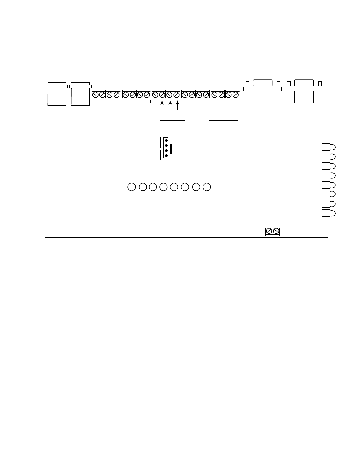
API-8/232 Connections
LINE
PHONE
~ ~ + -
BAT
POWER
NC
NO
COM
TROUBLE
1 2 3 4 5 6 7 8
(INPUT LED INDICATORS)
COMMON
SILENCE
DRY
1 2 3 4 5 6 7 8
INPUTS
WET
JP1
SERIAL
PORT OUT
(PROGRAM)
SYSTEM RESET
SERIAL
PORT IN
PWR
LINE
CALL
BUSY
PAGE
DATA
LOAD
TRBL
LED INCDICATOR CONDITIONS
Power: illuminated when power supplied
Line: illuminated when telephone line voltage is present (on hook), LED is off when unit dials
Call: illuminates when unit initiates outgoing call (either direct connect or dial-up)
Busy: illuminates when telephone line is busy
Page: flashes once for each page successfully sent to the terminal
Data: not presently used
Load: illuminated when downloading/uploading from programming software
Trbl: illuminated when unit is in trouble condition i.e loss of line, loss of power, retries reached
INPUT LED INDICATORS
Dry Contact: input LED illuminated when contact is in ‘closed’ condition
Wetted Voltage: input LED illuminated when voltage is supplied to contact
PAGE 3-1
INSTALLATION
Page 14

1. Mount the API-8/232 in the desired location and connect the plug in transformer (if supplied) to a source
of power (120 Volts 60Hz). The LED marked “Power” will illuminate indicating that the board is
powered up.
NOTE: Remove power while making external connections.
Opto Input Connections
2. In order to make connections to API-8/232 it is necessary to remove the enclosure cover (if supplied).
Remove the four Philips machine screws which secure the cover to the base of the enclosure.
3. Select either dry contact or wetted voltage inputs via jumper placement on JP1. To select for dry contact
inputs leave the two jumpers in place as factory installed. To select for wetted voltage inputs. place
single jumper over pins two and three (as indicated on board).
NOTE: Wetted voltage inputs must not exceed 48 Volts. Excessive Voltage will cause damage to the
unit. Never connect wetted voltage inputs to the input terminals if the on board jumpers are in the
“DRY” position.
4. Connect a single wire from the normally open or normally closed contact outputs that are to be
monitored to the terminals marked INPUTS 1 through 8. Connect a common lead from each of the
outputs that are to be monitored to one of the terminals that are marked “Common”.
NOTE: Wires for external connections can be routed through the pre-punched hole located on the
end of the enclosure base.
RS-232 Input Connection
5. Connect an RS-232 cable from the serial port on the host system to be monitored to the DB9 female
“SERIAL PORT IN” located on the API-8/232. After replacement of the cover and screws, the unit may
be Powered up.
NOTE: Pin outs for the API-8/232 “SERIAL PORT IN” must match the pin assignments for the host
system that is being monitored.
API-8/232 “SERIAL PORT IN” Pin Outs
Pin 2 Tx
Pin 3 Rx
Pin 5 Gnd
PAGE 3-2
Paging System Connections
Direct Connection
Page 15

1. Connect the “SERIAL PORT OUT” to an available direct connect port on the Paging Terminal. The
“Paging System Direct Connect Cable” (if supplied) is configured for direct connection to the Motorola
People Finder Encoder/Transceiver “EIA RS232C Port”. For other paging terminals see manuals to
determine required cable configurations.
NOTE: Pin outs for the API-8/232 “SERIAL PORT OUT” must match the pin assignments for the paging
system.
API-8/232 “SERIAL PORT OUT” Pin Outs
Pin 2 Tx
Pin 3 Rx
Pin 5 Gnd
NOTE: The Paging Terminal Input Port must be programmed at the following communication
parameters:
Baud Rate 1200
Parity Even
Data Bits 7
Stop Bits 1
OR
Remote Paging Terminal Connection
1. Locate and connect a normal analogue telephone line to the RJ11 connection marked “LINE”.
2. Check the LED marked “LINE”. If dial tone voltage is present the LED will be illuminated.
NOTE: The unit must be connected to a single analogue telephone line or extension that is DTMF
capable (POTS).
PAGE 3-3
CHAPTER 4
PROGRAMMING
Page 16
Pager Interface Programming (PIP) Module Software Installation
1. Start Microsoft Windows 95or NT
2. Insert the Pager Interface Programming (PIP) Software Disk 1 into drive a: (or b: )
3. In Program Manager, choose RUN from the File menu
4. Type a:\setup32
5. The installation program will guide you through the set up procedure.
6. The Pager Interface Programming Module Icon will appear on the screen
7. Double click on the icon to activate the programming software.
API-8/232 Programming Connections
1. Connect the API-8/232 Paging Interface Programming Cable (supplied) from a comm port on the PC
where the PIP Software is loaded to the DB9 “SERIAL PORT OUT (PROGRAM)” on the API-8/232.
API-8/232 Programming Instructions
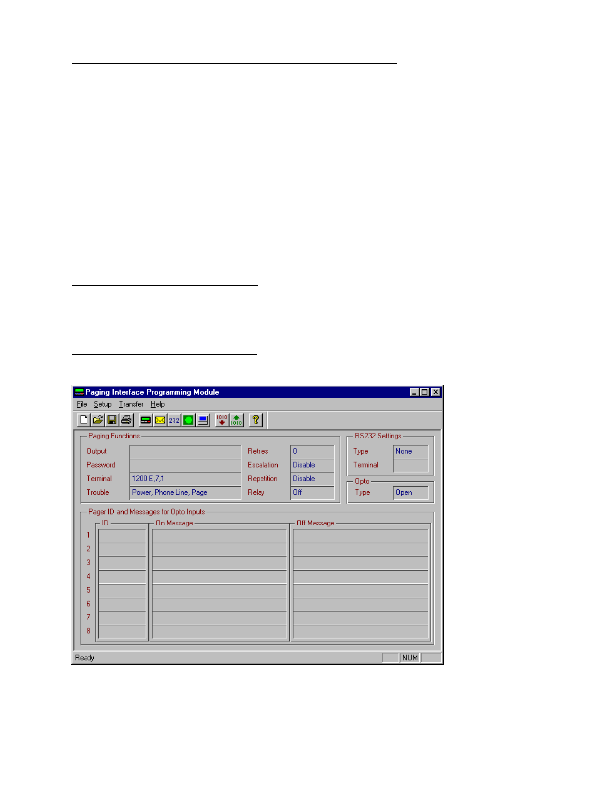
1. Open the PIP software by double clicking on the PIP Icon. The following window is displayed.
PAGE 4-1
2. From the Setup menu select Computer and from the sub-menu that appears select Port. The following
Window is displayed.
Page 17
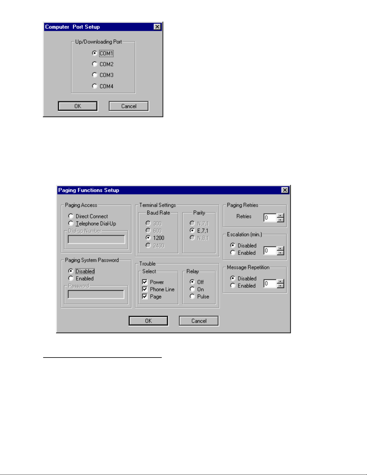
3. Select the communications port on the computer which is connected to the API-8/232 via the
programming cable. Click OK.
4. From the Setup menu select Board and from the sub-menu that appears select Paging Functions. The
following Window is displayed.
Paging Terminal Direct Connection Setup
1. In the paging Access Box select Direct Connect.
2. In the Paging System Password box select Disabled if the paging system does not require a password.
If the paging system requires a password select Enabled. Enter the password in the Password field.
3. In the Terminal Settings Box select Baud Rate 1200 and Parity E,7,1. Please note that this is the default
setting. These settings will always revert to the default when Direct Connect has been selected.
PAGE 4-2
4. In the Trouble, Select box the trouble conditions that are to be monitored by clicking the check boxes.
Page 18

5. In the Trouble, Relay box select Off, On or Pulse for the auxiliary trouble output relay.
6. In the Paging Retries box set the number of times the API-8/232 will attempt to connect with the paging
terminal before a trouble condition is generated (Value 1-99).
7. In the Escalation box select disabled if escalation of unacknowledged alarm messages is not required.
Select Enabled and enter a value between 1 and 60 minutes if escalation of alarm messages is required.
8. In the Message Repetition box select Disabled if message repetition is not required. Select Enabled and
enter a value of 1 or 2 if message repetition is required.
9. Click OK.
Remote Paging Terminal Access Setup
1. In the Paging Access Box select Telephone Dial Up. Enter the telephone number required to access the
paging terminal (up to 20 characters). If a pause is required in the dial string use a comma (,). Each
comma that is entered in the dial string provides a one second pause.
2. In the Paging System Password box select Disabled if the paging system does not require a password.
If the paging system requires a password select Enabled. Enter the password in the Password field (up
to 20 characters).
3. In the Terminal Settings Box select the terminal Baud Rate and Parity of the paging terminal. Please
note that the default setting of Baud 1200, Parity E,7,1 is compatible with most paging terminal modem
access ports.
4. In the Trouble, Select box select the trouble conditions that are to be monitored by clicking the check
boxes.
5. In the Trouble, Relay box select Off, On or Pulse for the auxiliary trouble output relay.
6. In the Paging Retries box set the number of times the API-8/232 will attempt to connect with the paging
terminal before a trouble condition is generated (Value 1-99).
7. In the Escalation box select disabled if escalation of unacknowledged alarm messages is not required.
Select Enabled and enter a value between 1 and 60 minutes if escalation of alarm messages is required.
8. In the Message Repetition box select Disabled if message repetition is not required. Select Enabled and
enter a value of 1 or 2 if message repetition is required. Click OK.
Note: If repetition is enabled a value of 1 will indicate that the On messages will be paged out
twice (ie. repeated once). A value of 2 will indicate that the ‘ON’ messages will be
paged out three times (ie. repeated twice).
PAGE 4-3
Opto Input Type Setup
Page 19

1. From the Setup menu select Board and from the sub-menu that appears select Opto Input Type.
The following Window is displayed.
2. Select either Normally Open or Normally Closed. This selection should match the output type
of the normal contact condition on the host system. A change from the selected normal input
condition initiates the “ON” message to the pager. Click OK.
Opto Input Message Setup
1. From the Setup menu select Board and from the sub-menu that appears select Paging Messages.
The following Window will appear.
2. Select the Input Point number to be programmed by clicking on the corresponding Input Select
Button.
3. Click the cursor in the Pager ID box and enter the pager number that messages for this input are
to be sent to.
PAGE 4-4
Page 20

2. Click the cursor (or use Tab Key) into to the ON Message box. Type the ON Message (maximum of 80
characters) for this input. The ON message is sent when the input status changes from the normal
condition to the alarm condition.
3. Click the cursor (or use Tab key) into the OFF Message Box. Type the OFF Message (maximum of 80
characters) for this input. The OFF message is sent when the input status changes back to the normal
condition.
4. Repeat above process for each input that is to be used. When moving between inputs in the Paging
Messages Setup Window, changes are automatically saved. When finished programming all of the
required inputs Click OK.
RS232 Serial Data Input Setup
1. From the Setup menu select Board and from the sub-menu that appears select RS232 Data Type. The
following Window will appear.
2. In the Selection box select Serial Data.
3. In the Terminal Settings box select the Baud Rate and Parity Settings to match the host system serial
port settings.
4. In the Paging Characters box enter the maximum number of characters that the paging carrier or system
manager will allow in a single alphanumeric message.
PAGE 4-5
Page 21

Setup API-8/232 to Page All Events Generated Via Host System Serial Port
1. Within the Serial Data Configuration box , Key Strings section, select Disable.
2. Enter the pager ID number in the Default ID box. All events that are delivered to the “Serial In Port” on
the API-8/232 will be sent to the pager or group of pagers that the Default ID number is assigned to.
Setup API-8/232 to Page Selected Events Generated Via Host System Serial Port
1. Within the Serial Data Configuration box , Key Strings section, select Enable.
2. Enter the Key Word(s) from the first type of event that is to be paged in the Key String 1 (and/or Key
String 2) box. Enter the Pager ID in the ID field for Event Type 1. All events that are delivered to the
“Serial In Port” on the API-8/232 that contain the ASCII character string(s) specified in the Key String 1
and Key String 2 , fields will be sent to the pager or group of pagers assigned in the Event Type 1, ID
field.
3. Repeat for Key String Fields 2 through 8 if required.
IMPORTANT NOTES ON THE USE OF KEY STRINGS:
(1) API-8/232 is case sensitive. Incoming data from the host system that is to be paged must contain
Key Strings that are an identical match for the words programmed in the Key String fields.
(2) When the Key String box is Enabled any events that are delivered to the “Serial In Port” on the API-
8/232 that do not contain any of the ASCII character strings specified in any of the Key String fields,
will be discarded and not paged.
(3) When two Keywords are used as search criteria to identify a valid Event String, both the First Key
String and the Second Key String must be found in the incoming data string for API-8/232 to
identify the string as valid (to be paged).
Setup API-8/232 to Identify the End of Each Incoming ASCII String from the Host System
1. Within the Ending ASCII Configuration box , select the first ASCII character that identifies the end of
an incoming ASCII string generated by the host system from the menu in box 1.
2. Repeat for Ending ASCII boxes 2,3 and 4 to define the ASCII characters which define the end of an
event that is generated by the host system.
PAGE 4-6
IMPORTANT NOTES ON THE USE OF ENDING ASCII CHARACERTS
Page 22

1. Ending ASCII characters must be selected in the order that they appear at the end of the ASCII strings
generated by the host system.
When Key Strings are not Enabled:
API-8/232 will page everything that is found in the incoming ASCII string field. The Incoming ASCII
string field is defined as all ASCII characters that come after the end of the last ASCII string and everything
that comes before the ending ASCII characters (as programmed in the Ending ASCII section of the RS232
Setup Menu).
When Key Strings are Enabled:
API-8/232 will search each event, defined by the ending ASCII , for the Event Types that are defined in the
Key Strings Section of the programming. The ending ASCII defines the field in which API-8/232 should
search for the Key Strings that have been programmed. API-8/232 will page all of the characters which are
found in the ASCII string field, defined by the ending ASCII, subject to the Key String Matches being found
in the field.
Setup API-8/232 to Modify Messages Generated Via Host System Serial Port
1. Within the Message Modifiers box , Click the cursor (or use Tab key) into Generic Header Field. Type
in a header up to 20 characters in length. The header will appear at the start of every message received
by the pager(s).
2. Click the cursor (or use Tab Key) into the Character Masks field. Type in up to 20 characters which are
to be eliminated from the paged messages. Characters that are entered in this f ield will be rem oved from
any valid message string. Any message which contains only characters which appear in the Character
Masks field will be discarded and not paged.
3. Click the cursor (or use Tab Key) into the Consecutive Spaces Field. Enter an integer between 1 and 9.
Consecutive spaces in any valid message string in excess of the integer entered in this field will be
removed from the page and will be replaced with a single space.
When all of the parameters in the RS-232 Window are complete Click OK.
PAGE 4-7
RS232 SETUP MENU - Programming Example
Page 23

Down Loading Data to API-8/232
1. From the Transfer menu select GO. The following Window will appear.
2. In the Transfer Direction box select Download Data to Board.
3. In the Transfer Execution Box Click GO. The Data Transfer Window will appear.
PAGE 4-8
Page 24

4. During data transfer the LOAD LED will be illuminated.
5. When data transfer is complete (progress bar in Data Transfer Window is at 100%) a message box
appears indicating Upload Successful. Click on OK.
Up Loading Data from API-8/232
1. From the Transfer menu select GO.
2. In the Transfer Direction box select Upload Data from Board.
3. In the Transfer Execution Box Click GO. The Data Transfer Window will appear.
4. During data transfer the LOAD LED will be illuminated.
5. When data transfer is complete (progress bar in Data Transfer Window is at 100%) a message box
appears indicating Upload Successful. Click on OK.
Saving and Opening Programming Data Files
1. Upon completion of programming, the API-8/232 data may be saved as a file for retrieval or
Re-programming of the unit.
2. To save a file, from the File menu select Save As.
3. In the ‘Save In’ box, select the directory/drive to which the file is to be saved.
4. In the ‘File Name’ dialogue box, type in the name of the file to be saved. Click on Save.
5. To open a previously saved file, from the File menu select Open.
6. In the ‘Look In’ box, select the directory/drive to which the file has been saved.
7. In the ‘File Name’ dialogue box, type in the name of the file to be opened. Click on Open.
Note: The paging interface programming data files will be saved in the following
format: filename.pip
PAGE 4-9
CHAPTER 5
Page 25

TROUBLE SHOOTING
TROUBLE SHOOTING
If API-8/232 is not performing properly , use the following troubleshooting chart for solutions to common
problems. If the problem persists, call the dealer where you purchased the product. If further support is
needed call the Monitor Technologies customer support line. Customer Service Support is available at 1800-452-4565 (for Canada or U.S. only).
Problem Possible Cause Remedy
NO POWER:
Power LED Does not Illuminate
PHONE LINE TROUBLE:
Line and Trouble LEDs Flash
simultaneously and trouble piezo sounds
(Only when Remote Paging Terminal
Access has been programmed see page 43 for Setup instructions)
No power source connected
Power Source Connected at Incorrect
Location
Power Source above/below specified
ratings
No telephone line connected
Incorrect type of telephone line
connected
The telephone line does not provide onhook dial tone voltage
The telephone line is equipped with
automated voice answer service provided
by the telephone company. True dial
tone is replaced by a pulsing audible
signal when there is a voice message
waiting to be picked up
Other equipment is busy utilizing the
telephone line
Connect Plug in Power Transformer (If
Supplied) or Connect alternate
appropriate power source (refer to Power
Supply Specifications on Page 2-2)
Connect Power Source to correct
terminals (refer to Connection Diagram
on Page 3-1) NOTE: Connecting a
power source to the input terminals when
the on-board jumpers are in the “DRY”
position will cause damage to the unit.
Connect appropriate power source (refer
to Power Supply Specifications on Page
2-2)
Connect a telephone line to RJ11
connector marked “LINE”
Connect an analogue telephone line or
extension
Ensure that the telephone line is equipped
to provide on-hook dial tone voltage
Disable the audible signal feature of the
automated voice answer service or
remove this service from the line
Disconnect other devices from the line
PAGE 5-1
Problem Possible Cause Remedy
BUSY TROUBLE:
Paging Terminal modem(s) consistently Increase “Paging Retries” in “Paging
Page 26

Telephone Line or Paging Terminal
Modem Busy . “BUSY” LED continues
to Flash on every page attempt
PAGING FAILURE TROUBLE:
Paging Failure after Retry Attempts are
exhausted
(“BUSY”, “PAGE” and “TRBL” LEDs
flash if the API-8/232 is setup for
“DIRECT CONNECT” Paging Access
in the “PAGING FUNCTIONS SETUP
MENU”)
(“LINE” ,“BUSY”, “PAGE” and
“TRBL” LEDs flash if the API-8/232 is
setup for “TELEPHONE DIAL-UP”
Paging Access in the “PAGING
FUNCTIONS SETUP MENU”)
busy
Outgoing telephone line is consistently
busy
Dial string requires an area code to access
the paging terminal
Dial string requires a prefix to access an
outside line
Dial String requires a pause between
prefix required to access an outside line
and the phone number required to access
the paging terminal
Paging Access has been incorrectly
programmed in the Paging Functions
Setup Menu
Dial Up Number for Accessing The
Paging Terminal is incorrect
THE MOST COMMON ERROR IS
THAT A PAGER ID NUMBER HAS
BEEN ENTERED IN THE “DIAL-UP
NUMBER” FIELD IN THE “PAGING
SYSTEM SETUP” MENU.
Functions Setup” Menu
Increase “Paging Retries” in the
“Paging Functions” Setup Menu Or
Connect another available analogue
telephone line that has less/no alternate
uses
Include the area code in the “Dial-up
Number” field in the “Paging Functions
Setup” Menu
Include the required prefix in the “Dialup Number” field in the “Paging
Functions Setup” Menu
Use Comma’s in the “Dial-up Number”
field in the “Paging Functions Setup”
Menu to create a one second pause in the
dial string. This is most often required
between the prefix required to access an
outside line and the phone number
required to access the paging terminal.
Enter all required digits in the “Dial-Up
Number” field in the “Paging Functions
Setup” Menu. Include any prefix digits
required to access an outside line, any
pauses required in the dial string and the
area code if required. An example DialUp String may look like this
9,1115551234
Where:
9 is required to access an outside line
The Comma(,) provides a one second
pause
111 is the area code required to dial the
paging terminal
and 555-1234 is the paging system dial
up-number
Check that the access number provided
by the paging supplier or system manager
is the correct one. The Dial-Up Number
is the telephone number that accesses a
modem pool at the paging terminal.
This is the number that can be used to
send alphanumeric messages from a PC
or other alphanumeric message entry
device. It is not
Check that the number you have obtained
is the right one by dialing the number
from any telephone handset. Once
connected you should hear modem tones.
If you dial the Paging Access Dial-Up
Number and you receive a voice prompt,
you have the wrong number.
the pager ID number.
PAGE 5-2
Problem Possible Cause Remedy
PAGING FAILURE TROUBLE:
Paging Failure after Retry Attempts are
Paging System Password (programmed
in the Paging Functions Setup Menu)
Program the correct Password as
provided by the paging supplier or
Page 27

exhausted (CONTINUED FROM LAST
PAGE).
CAN’T UPLOAD/DOWNLOAD
“LOAD” LED does not illuminate and
Communication Error Dialogue Box
Appears while Uploading/Downloading
programming data
does not match Password required by
Paging terminal for successful
communication
Paging Communication Settings do not
match settings required by Paging
terminal for successful communication
Pager ID number(s) is not valid
Pager is not correct type or is not
programmed to receive type of data being
sent by API-8/232
Incorrect Computer Port Setup Selection
Programming Cable connected to
incorrect port on PC used for
programming
Programming Cable connected to
incorrect port on API-8/232
Incorrect Cable used for
Uploading/Downloading
API-8/232 is processing /sending
Messages
system manager. Enable the Paging
System Password in the “Paging System
Setup” Menu and Enter. Enter the
correct password in the “PAGING
SYSTEM PASSWORD” Field.
Program the correct communication
settings as provided by the paging
supplier or system manager. Select the
correct “Terminal Settings” in the
“Paging System Setup” Menu. The
Default Terminal Settings are 1200 Baud,
Parity E,7,1.
Confirm that the Pager ID# provided by
the paging supplier or system manager is
active and valid. Send a test page from
another Message Entry Device (Touch
Tone Phone, Alphanumeric Messaging
Software or Dedicated Message Entry
Device).
When sending Alphanumeric Messages
using the API-8/232 ensure that the pager
is capable of receiving full text messages.
From the “Computer Port Setup” Menu
select the COM Port on the PC that is to
be utilized for programming.
Connect the API-8/232 Programming
Cable to the Correct Port on the PC that
is to be used for programming.
Connect the API-8/232 Programming
Cable to the “Serial Out (Program)” Port
on the unit (see Connection Diagram on
Page 3-1).
Use the API-8/232 Programming Cable
that is supplied with the unit.
Wait for API-8/232 to send all messages
which are pending in memory.
Or
Momentarily short the “RESET”
terminals to clear all messages from
memory.
PAGE 5-3
Problem Possible Cause Remedy
RS232 DATA NOT BEING
RECEIVED BY API-8/232
“DATA” LED does not illuminate and
Paging sequence is not initiated when
RS232 Cable connected to incorrect port
or terminals
Incorrect Comm Port Setup or Selection
Connect RS232 at Correct Location on
host system.
Set Up the communications port on the
Page 28

RS232 data transferred - API-8/232 is not
R
receiving data from host system
RS232 DATA NOT BEING PAGED
“DATA” LED illuminates and Paging
sequence is not initiated when RS232
data transferred - API-8/232 is receiving
data from host system but is not paging
information
on host system
API-8/232 Not programmed to Accept
RS232 Data
RS232 Cable connected to incorrect port
on API-8/232
Incorrect Cable configuration
Incorrect Data Type Selection in RS232
Setup Menu
Incorrect Terminal Settings in API-8/232
“RS232 Setup” Menu
If Keystrrings are enabled, Incoming
Data does not contain a match for any of
the Keystrings programmed in the RS232
Setup Menu. Important Note: Keystrings
are case sensitive (API-8/232 will only
identify Keystrings which are an exact
match for strings contained in incoming
Data).
Data is not RS-232/ASCII or is of some
unknown format or utilizes unknown
protocol.
1. Uploading or Downloading Programming Information:
API-8/232 LED INDICATORS
host system using manufacturers
instructions. Note: Program API-8/232
“Terminal Settings” in the “RS232
Setup” Menu to match those of the host
system.
Program API-8/232 to accept RS232
ASCII Data. In the “RS-232 Setup”
Menu select “Serial Data. Program
“Terminal Settings” in the “RS232
Setup” Menu to match those of the host
system.
Connect RS-232 cable from the host
system to the “Serial Port In” connector
on the API-8/232 (see connection
Diagram, page 3-1).
From the host System Connect the Tx to
the Rx on API-8/232 (Pin 3) From the
host System Connect the Rx to the Tx on
API-8/232 (Pin 2). From the host
System Connect the Gnd to the Gnd on
API-8/232 (Pin 5).
To Program API-8/232 to accept RS232
ASCII Data: In the “RS-232 Setup”
Menu select “Serial Data”.
Program “Terminal Settings” in the
“RS232 Setup” menu to match those of
the host system.
Program “Keystring” Fields in the “RS232” menu to identify text that is found
within the events generated by the host
system that are to be paged.
Connect API-8/232 to an RS-232 port
that provides ASCII data strings for event
reporting purposes.
PAGE 5-4
D
L
E
E
Y
L
L
Y
E
D
E
L
L
E
Y
D
E
L
Page 29

PAGE 5-5
SUPPORT AND INFORMATION
FOR INFORMATION REGARDING API-8/232, PLEASE CALL OR WRITE TO MONITOR
TECHNOLOGIES AT:
Page 30

Monitor Technologies Inc.
9011 Leslie Street, Suite 102
Richmond Hill, Ontario
L4B 3B6
Telephone: (905) 889-6511
Fax: (905) 889-6235
E-mail: rob@mtca.com
Web Site: www.mtca.com
PAGE 5-6
 Loading...