

Page 1
API- 64, API-64EM, API-64RM, TABLE OF CONTENTS
CHAPTER 1
INTRODUCTION. 1-1
PURPOSE OF MANUAL. 1-1
CHAPTER 3
INSTALLATION/OPERATION
API-64 CONNECTIONS. 3-1
API-64EM CONNECTIONS. 3-2
API-64RM CONNECTIONS. 3-2
SYSTEM INSTALLATION. 3-3
CHAPTER 2
DESCRIPTION
INTRODUCTION. 2-1
DESCRIPTION. 2-1
COMPATIBILITY. 2-1
SPECIFICATIONS. 2-3
FEATURES.2-4
CHAPTER 4
PROGRAMMING API-64/API-64EM
PROGRAMMING NOTES.4-1
MENU.4-2
SYSTEM SETUP MENU.4-3
MESSAGES SETUP MENU.4-4
DATA LOGGING HISTORY.4-7
API-64RM PROGRAMMING.4-8
SUPPORT AND INFORMATION
INSTALLATION/OPERATION MANUAL
Installation of this product in accordance with this manual,
applicable codes, and the instructions of the Authorities Having
Jurisdiction is mandatory.Monitor Technologies Inc. shall not
under any circumstances be liable for any incidental or
consequential damage arising from loss of property or other
damages or losses owing to the failure of Monitor Technologies,
Inc. products beyond the cost of repair or replacement of any
defective products.Monitor Technologies Inc. reserves the right to
make product improvements and change product specifications at
any time.he contents of this manual and the related software
program are proprietary in nature and are intended solely for the
distribution to authorized persons, companies, distributors and or
others for the sole purpose of conducting business associated with
Monitor Technologies Inc.. The distribution of information
contained within this manual to unauthorized persons shall
constitute a violation of any distributor agreements and may
require the implementation of legal proceedings.While every
precaution was taken during the preparation of this manual to
ensure the accuracy of its contents, Monitor Technologies Inc.
assumes no responsibility for errors or omissions.
CHAPTER 1
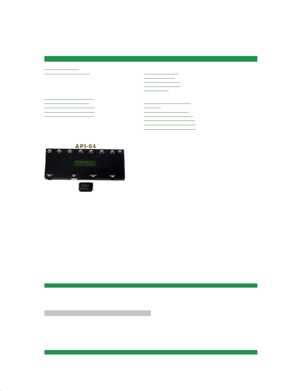
The Alphanumeric Paging Interface processes custom message information into a format that allows
messages to be broadcast over standard radio paging architecture. The interface activates through dry
contact or wetted voltage inputs.
PURPOSE OF THE MANUAL
This manual provides descriptions and instructions for programming, installing and maintaining the
Alphanumeric Paging Interface. A Brief description of the remaining chapters is as follows.
Chapter 2 - Description of functions and capabilities including specificatio ns.
Chapter 3 - Installation, Power Up and External Connections.
Chapter 4 - Programming Instructions
Chapter 5 - troubleshooting
CHAPTER 2 DESCRIPTION
Page 2

INTRODUCTION 2-1
This chapter describes the characteristics, capabilities, features and specifications of the Alp hanu meric
Paging Interface.
DESCRIPTION
The Alphanumeric Pager Interface alerts individuals via display pagers of a change in status from a given
output. When a status change occurs via a change in a dry contact or wetted voltage input an alarm message
is delivered to the paging terminal's IXO port via phone line or through a direct connect RS-232 serial port
connection. The interface encodes messages per paging industry standard "Telecator Alphanumeric Paging"
(TAP) protocol to deliver messages from a location remote to the paging terminal via a telephone line
(Model API-64RM). The interface encodes messages per paging industry standard TAP or COMP2
protocols to deliver messages directly to a paging terminal RS-232 (Serial) Input. The maximum distance
between the Paging Interface and the paging terminal for RS-232 connection is 150 feet.
The paging terminal encodes messages received from the Alphanumeric Paging Interface and sends them
via a radio paging network to the designated alphanumeric paging receiver or group of receivers.
The Alphanumeric Pager Interface is compatible with both Privately Owned Paging Systems or Radio
Common Carriers' (RCC) Systems. Privately Owned Paging Systems
are typically site specific and cover a facility or building. They are privately owned and usually licensed for
use by one organization. RCC Paging Systems cover a larger geographical area and are utilized by the
licensee to provide paging services to organizations and private individuals.
The Alphanumeric Paging Interface (API-64) and Expansion Module (API-64EM) come with their own
steel enclosure, 110 V AC power cord and pluggable input terminal blocks. The API-64RM Remote Dial
Module comes with its' own steel enclosure, 120 V AC plug in transformer, connection cable and standard
6 foot RJ11 telephone cable
Back To Index
COMPATIBILITY
The Alphanumeric Paging Interface communicates with Paging Terminals via modem to modem Phone
Line Connection or via RS-232 c onnection.
Note: Where a Privately Owned Paging System provides telephone access for alphanumeric paging (from a
location remote to the terminal), API-64 can be utilized to dial in and deliver messages to the terminal via
telephone lines and the TAP protocol. This eliminates the need to place the API-64 within 150 feet of the
paging terminal.
RS-232 Paging System Requirements:
1.The paging terminal and transmitters must be capable of receiving, encoding and transmitting binary data
(end user would typically have numeric and/or alphanumeric pagers).
2.The paging terminal and transmitters must be alphanumeric message capable.
3.The paging terminal must be TAP (Telecator Alphanumeric) or COMP2 protocol capable. These are the
protocols utilized by message entry devices such as the Motorola Alphamate when directly connected to the
paging terminal.
4.There must be a direct connect serial port available on the paging terminal for connection of the API-64.
5.The maximum distance (length of the RS-232 cable) between the paging terminal and the API-64 is 150
feet (45.6m).
Back To Index
API-64/API-64EM
SPECIFICATIONS
WEIGHT........................................... 2kg(4.4lbs)
DIMENSIONS................................... 6"H x 16"W x 2"D
mm H x mm W x mm D
Page 3

ENCLOSURE................................... METAL
WALL MOUNTING........................... METAL BRACKETS
COUNTER TOP............................... RUBBER FEET
TEMPERATURE RANGE................. 0C - 40C
INPUT POWER................................ 110V AC 60Hz
CONSUMPTION.............................. 20W MAX.
CONTACT INPUTS......................... 64 OPTICALLY ISOLATED (PROGRAMMABLE EITHER N/O
OR N/C)
CONTACT INPUT BLOCK 1-32...... SWITCHABLE DRY CONTACT OR WETTED VOLTAGE
CONTACT INPUT BLOCK 33-64.... SWITCHABLE DRY CONTACT OR WETTED VOLTAGE
WETTED VOLTAGE INPUTS........ 12-48V DC "ON STATE"
0V DC "OFF STATE"
DISPLAY SCREEN.......................... 240 x 64 GRAPHIC (8 LINE X 40 CHARACTER LCD) -API-64
Only
PROGRAMMING............................. AT/WIN95 COMPATIBLE KEYBOARD
RS-232 CONNECTION................... DB25 FEMALE
BAUD RATE.................................... 300 -4800 (PROGRAMMABLE)
NUMBER OF BITS/PARITY........... 7 & EVEN OR 8 & NONE (PROGRAMMABLE)
NETWORK CONNECTIVITY......... RS-485
EXPANSION MODULE .................. MAXIMUM NUMBER 15 (TOTAL NUMBER OF INPUTS 1024)
NETWORK DISTANCE.................. MAXIMUM LENGTH OF NETWORK - 4000 FEET
MESSAGE TYPE........................... ALPHANUMERIC
MESSAGE LENGTH..................... MAXIMUM 80 CHARACTERS
MESSAGE STORAGE.................. MAXIMUM 1,000
Remote Dial Module (API-64\RDM)
WEIGHT........................................... 1kg(2.2lbs)
DIMENSIONS................................... 6"H x 16"W x 2"D
mm H x mm W x mm D
ENCLOSURE................................... METAL
WALL MOUNTING........................... METAL BRACKETS
COUNTER TOP............................... RUBBER FEET
TEMPERATURE RANGE................. 0C - 40C
INPUT POWER SUPPLY.................. 120V AC 60Hz
CONSUMPTION............................... 400 ma. MAX.
PROGRAMMING.............................. DOS BASED PC WITH SAMI-PSV1.1 SOFTWARE
DIALING METHOD.......................... DTMF
MODEM............................................ 300 BAUD INTERNAL
RS-232 CONNECTION................... RJ11 FEMALE
BAUD RATE.................................... 1200
NUMBER OF BITS.......................... 8
STOP BITS..................................... 1
PARITY........................................... NONE
Back To Index
FEATURES
ALARM INPUTS
The Alphanumeric Paging Interface and each Expansion Module are equipped with 64 screw type
pluggable inputs for connection to dry contacts or wetted voltage points. The inputs are user programmable
as either normally opened or normally closed. Each Input can be programmed with a separate text message
for "Active", "Reset" and/or "Pulse" conditions. Messages can be up to 80 characters in length each. The 64
inputs are divided into two blocks of 32 inputs each. Each block of 32 inputs can be configured as either
dry contact or wetted voltage. The input points are opto-isolated to ensure no interference occurs between
the Alphanumeric Paging Interface (or Expansion Modules) and the device being monitored.
SYSTEM EXPANSION
Page 4

The Alphanumeric Paging Interface allows for expansion from 64 inputs to 1024. The number of inputs is
expanded by the addition of expansion modules (API-64EM). Each Module adds 64 points to the system.
The modules are daisy-chained to the API-64 via an RS-485 connection. Up to 15 Expansion Modules may
be added to each API-64 . Programming for all of the points in the network is done via the master API-64.
ALARM INFORMATION VECTORING
The preprogrammed alarm message(s) for each input may be designated to be sent to a specific pager ID
number. The messages for each point can be sent to specific users or groups of users who are designated to
receive the information. Selected individuals or user groups within a facility or organization may receive
detailed notification of conditions which apply to them specifically. The Alarm Paging Interface can be
connected to multiple input sources and can vector information from each source to the required
recipient(s).
ALARM PRIORITIZATION
Each individual input may be designated a level of priority ranging from A to J. Messages with higher level
priorities (A) are processed and paged before lower level priority (J) messages. Messages that are assigned
equal priority levels are processed and paged on a first in first out basis.
ESCALATION PAGING
Each input can be programmed for escalation paging if required. Escalation paging allows a given message
to be sent to a secondary and/or a tertiary pager ID# if the alarm condition persists for a pre-defined period
of time. The time between escalations is user definable and can be from one to thirty minutes. Escalation
applies to alarm conditions only. Alarm conditions are defined as a change in the status of an input from its
normal position (normally opened or normally closed) to "Active" or "Pulse".
MESSAGE LOGGING/PRINTING
The Alphanumeric Paging Interface stores the last 1,000 paged messages in a log file. This log file may be
printed via a parallel printer attached to the printer port. The log file can be viewed or printed for any user
specified time period.
REAL TIME CLOCK
The Alphanumeric Paging Interface has a built in real-time clock. The clock uses 24 hour format and
contains an internal battery to maintain accurate system time in case of power loss.
SHIFT SCHEDULING
The Alphanumeric Paging Interface can be programmed to allow for shift scheduling. Messages can be sent
to specific pagers during specific periods of time. The alarm message for a given input may be sent to one
pager ID# if there is a change in status during the day shift and to another pager ID# if there is a change in
status during the night shift. Escalation for each shift is user programmable.
IN-HOUSE PAGING APPLICATIONS
Connection to the paging system is made via one direct RS-232 connection. The Alphanumeric Paging
Interface delivers a message via direct connection to an available serial port. The paging terminal provides
information back to API-64 indicating acceptance or rejection of the message. If a message is rejected the
Alphanumeric Paging Interface immediately resends the message to the terminal and redelivers the
message (until the message is accepted by the paging terminal).
WIDE AR EA APPLICAT IONS
Connection to the paging system is made via telephone lines (requires API-64RM, Remote Dial Module).
The Remote Dial Module is connected via RS-232 to the Alphanumeric Paging Interface. API-64RM
connects with the paging terminal via telephone lines and delivers a message via an IXO port. The paging
terminal provides information back to the Remote Dial Module indicating acceptance or rejection of the
message. If a message is rejected the API-64RM immediately redials the terminal and redelivers the
message (up to 5 attempts).
PHONE LINE REQUIREMENTS (API-64RM)
Page 5

The Remote Dial Module requires a single line, DTMF telephone line in order to dial a paging system. The
API-64RM can share a telephone line with another piece of equipment or one that is in use for another
purpose (ie. a fax line). To ensure the API-64RM will seize a shared line that is in use, it must be the first
device on the phone line. If the API-64RM is down stream of another device (security or fire alarm panel)
the Module will sense the upstream equipment and will not atte mpt to use the line until 'ON HOOK'
voltage is re stored.
PROGRAMMING
The API-64 is programmed via a standard AT/WIN95 compatible keyboard. All of the programming
software is housed on board the API-64. A compatible keyboard is simply plugged into the keyboard port
on the unit. The use of a standard keyboard eliminates the requirement for specialize hardware and/or
software for programming.
Unified Construction
The API-64 is housed in a rugged metal enclosure with a LCD display screen. The alarm input port screw
terminals are housed in the enclosure as is the power supply. The unit is simply plugged into a standard
110Volt power supply and wired to the contact points for operation. PAGE 2-5
Back To Index
CHAPTER 3
INSTALLATION AND OPERATION
API-64 PANEL CONNECTIONS
A IEC Power Socket (110 V AC)
B Power Switch
C Pluggable Terminal Block for Commons - Inputs 1 through 32
D Pluggable Terminal Blocks for Inputs 1 through 32
E Pluggable Terminal Bl ock for Commons - Inputs 33 throu gh 64
F Pluggable Terminal Blocks for Inputs 33 through 64
G 5 Pin Socket for AT/WIN 95 Compatible Keyboard
H 25 Pin Connector for RS-232 Connection to Paging Terminal or Remote Dial Module
I 240 X 64 Graphic LCD Display
Back To Index
API-64EM PANEL CONNECTIONS
API-64RM PANEL CONNECTIONS
INSTALLATION INSTRUCTIONS API-64
(1) Set Input Groups 1-32 and 33-64 for Dry Contacts or Wetted Voltage to match the input type that will
be wired to the pluggable contact input blocks. The input type for points 1 through 32 is selected by using
the WET/DRY slide switch located at the back of the Alphanumeric Paging Interface, below the common
pluggable input block for points 1 through 32. The input type for points 33 through 64 is selected by using
the WET/DRY slide switch located at the back of the Alphanumeric Paging Interface, below the common
pluggable input block for points 33 through 64.
WARNING: WIRING INPUTS THAT ARE OF A DIFFERENT TYPE THAN HAVE BEEN SELECTED
USING THE WET/DRY SWITCHES MAY DAMAGE THE UNIT. MAKE SURE THAT THERE IS NO
EXTERNAL VOLTAGE CONNECTED TO INPUT BLOCKS BE FORE SELECTING DRY.
(2)Connect all input wiring from the device(s) being monitored based on the example connection diagram
shown on Page 3-1.
(3)Connect all Expansion Modules (API-64EM) via RS-485 connections shown on page 3-2. Address each
of the expansion modules using the following instructions:
Remove the cover from the top of the expansion module (API-64EM)
Page 6

There is one block of four dip switches on the circuit board inside the unit.
Set The Dip Switches for Each Expansion Module Using the Table Below:
Expansion Module Dip Switch Settings Station Nu mber
1 2 3 4
1st API-64EM off off off off 02
2nd API-64EM on off off off 03
3rd API-64EM off on off off 04
4th API-64EM on on off off 05
5th API-64EM off off on off 06
6th API-64EM on off on off 07
7th API-64EM off on on off 08
8th API-64EM on on on off 09
9th API-64EM off off off on 10
10th API-64EM on off off on 11
11th API-64EM off on off on 12
12th API-64EM on on off on 13
13th API-64EM off off on on 14
14th API-64EM on off on on 15
15th API-64EM off on on on 16
(4)Plug an AT/WIN95 Compatible Keyboard into the 5 Pin Socket Labeled "KEYBOARD".
(5)Connect the API-64 to the paging terminal or to the API-64RM via the DB-25 connector labeled "RS232" using the cables supplied with the system.
(6)Connect the API-64 to the parallel system printer (if one is being used) to the DB-25 connector labeled
"PRINTER".
PAGE 3-3
(7)Turn the API-64 (and all expansion modules) on using the toggle switch labeled "POWER ON" that is
located on each unit. Program the API-64 and all API-64EM modules connected to the system using the
Programming Instructions that start on page 4-1.
Back To Index
CHAPTER 4
PROGRAMMING INSTRUCTIONS
API-64/API-64EM PROGRAMMING NOTES
1.Use the Directional Arrow Keys (<LEFT>, <RIGHT>, <UP>, <DOWN>) to move from field to field
while programming. When the cursor has been moved to a field, the data in that field will flash. The data
for that field can then be altered using the instructions below.
2.Use the <PAGE UP>/<PAGE DOWN> keys to increment/decrement data in any given field. Use the
<number> keys to increment/decrement data in fields that contain numeric data.
3.Use the <F1> key to save any programming changes that have been made for any menu, station, or input
throughout programming procedure .
4.Use the <ESCAPE> key to leave any menu and return to the main menu. If you <ESCAPE> before any
programming changes have been saved, the changes will not be saved.
5.If the system is paging "GOLAY" type alphanumeric pagers (the paging supplier or system manager can
provide that information) the following characters in a message string are invalid:
Back To Index
Page 7

MAIN MENU DESCRIPTION
The main menu is displayed when the API-64 is powered up, when you exit from any of the other menus or
the system times out of another menu. A system time out occurs when no data or programming changes
have been made while in another menu for 30 seconds. If a system time out occurs, data changes that have
been made in the last menu will not be saved.
Main Menu Display
-------------------- MAIN MENU --------------------
01 02 03 04 05 06 07 08 DATE: 09/20/96
09 10 11 12 13 14 15 16 TIME: 01:02:03
STATUS: READY FOR PAGING ----------------
09/30/96 10:20:00 01-01-ACTIVE ID: 1234
ROOM 101 BEDSIDE NEEDS ASSISTANCE
MENU SELECT: SYSTEM SETUP
-----------------------------------------------------------
Back To Index
(1) The header information contains the name of the menu that is presently displayed "MAIN MENU".
(2) NUMBERS 01 THROUGH 16: These are the ID numbers of units on the network (API-64 and API64EM). 01 is the ID number of the API-64 Alphanumeric Interface and 02 through 16 are the ID numbers
of the expansion modules. Only the ID numbers of devices connected to the network are displayed. If there
are 3 expansion modules (API-64EM) on the network then this part of the display would read "01 02 03
04". If there's a communication error with one of the expansion modules then the ID for that unit is
replaced by "--".
(2) DATE: Todays Date in the MM/DD/YY format (as programmed in the "SYSTEM SETUP MENU").
(3) TIME: Todays Time in the HH:MM:SS format(as programmed in the "SYSTEM SETUP MENU")
(4) STATUS: The system status displays "READY FOR P AGING" when idle, " TX CONNECTING"
when delivering a page or "CONNECTION ERROR" if a communication prob lem occurs while attempting
to deliver a page.
(5) Under the "STATUS" line the display shows the time and date of the last message that was processed
and sent by the system followed by the station number and input number that changed status followed by
the pager ID# that the last message was sent to.
(6) The text message that was sent for the last transaction is displayed below item (5).
(7) MENU SELECT: This field allows you to toggle between "SYSTE M SETUP", "MESSAGES SETUP"
and "DATA LOGGING HISTORY". Use the <PAGE UP>/<PAGE DOWN> keys and then <ENTER> to
select the menu you wa nt to acc ess.
Back To Index
SYSTEM SETUP MENU - DESCRIPTION AND
PROGRAMMING
The "System Setup" menu is used to set the global parameters for the Alphanumeric Paging Interface and
any Expansion Modules that may be connected to form the overall system.
System Setup Menu Display
Page 8

-------------------------SYSTEM SETUP------------------------
STATIONS : INPUT PULSE
RS232 BAUD: INPUT STATUS
RS232 BIT:
PAGE FORMAT: DATE: / /
PAGE SHIFT: TIME: : :
------------------------------<F1> SAVE---------------------------
(1) The header information contains the name of the menu that is presently displayed ("SYSTEM
SETUP").
(2) STATIONS is the number of devices connected via the RS485 network. It is defined as the
Alphanumeric Paging Interface (API-64) plus the number of Expansion Modules (API-64EM) in the
overall system. If the system is composed of one API-64 then this field should read "01". If the system is
composed of the Alphanumeric Paging Interface (API-64)and five Expansion Modules then this field
should read "06". Use the <PAGE UP>/<PAGE DOWN> keys to toggle to the correct number of stations.
(3) RS232 BAUD is programmable from 300 to 4800. It should be set to be compatible with the paging
system that is being utilized when direct connecting (via the RS-232). The baud rate should be set to 1200
if the (API-64RM) remote dialing module is utilized. Use the <PAGE UP>/<PAGE DOWN> keys to
toggle to the correct baud rate for the system.
(4) RS-232 BIT field allows you to set the system to 7 bits and even parity or 8 bits and no parity. It should
be set to be compatible with the paging system that is being utilized when direct connecting (via the RS-
232). The RS-232 BIT field should be set to 8/NONE if the (API-64RM) remote dialing module is utilized.
Use the <PAGE UP>/<PAGE DOWN> keys to toggle between 7/EVEN and 8/NONE.
(5) PAGE FORMAT refers to the paging protocol format that is being employed. If API-64 is direct
connected to a privately owned paging system then the transmission format may be set to either "TAP" or
"COMP2". When API-64 is connected to API-64RM (Remote Module) set the Page Format to "WIDE".
Use the <PAGE UP>/<PAGE DOWN> keys to toggle to the correct format ( TAP, COMP2 or WIDE)
(6) INPUT PULSE sets the system to accept a pulsing signal as a change in status and to allow the user to
set a "PULSE" message for each of the inputs that are in use. There are two options YES or NO. Use the
<PAGE UP>/<PAGE DOWN> keys to toggle between YES or NO.
NOTES:
If the INPUT PULSE field is set to NO then a message will be initiated as soon as an "ACT IVE" or a
"RESET" condition occur. If this field is set to YES then "ACTIVE" and "RESET" messages will only be
sent if the condition remains constant for five seconds or more. A momentary change in condition is
interpreted as a "PULSE" signal and the associated text message for "PULSE" for the given input will be
sent.
PAGE 4-3
(7) INPUT STATUS sets the "normal" state for all of the inputs that are in use on the system (the master
API-64 and all API-64EM expansion modules). There are two options N/O (normally opened) or N/C
(normally closed). Use the <PAGE UP>/<PAGE DOWN> keys to toggle between N/O or N/C.
NOTES:
If the system is programmed for N/O (normally open) inputs then a change in condition on any given input
from open to closed will initiate the "ACTIVE" message for that input. A change in condition from closed
to open will initiate the "RESET" or return to normal message. If the INPUT PULSE field has been set to
YES, a change in condition from open to pulse will initiate the "PULSE" message.
If the system is programmed for N/C (normally closed) inputs then a change in condition on any given
input from closed to open will initiate the "ACTIVE" message for that input. A change in condition fro m
Page 9

open to closed will initiate the "RESET" or return to normal message. If the INPUT PULSE field has been
set to Yes, a change in condition from closed to pulse will initiate the "PULSE" messa ge.
A change in condition on any given input from the "PULSE" state to the "RESET" state (normally open or
normally closed as configured in the "INPUT STATUS" field) will initiate the "RESET" message.
A change in condition on any given input from the "PULSE" state to the "ACTIVE" state will not i nitiate
any message. A change in condition on any given input from the "ACTIVE" state to the "PULSE" state will
not initiate any message.
(8) Date should be set to current date. Use the <PAGE UP>/<PAGE DOWN> or <NUMBER> keys to set
the date in the following format: (mm\dd\yy).
(9) Time should be set to the current time. Use the <PAGE UP>/<PAGE DOWN> or <NUMBER> keys to
set the time in 24 hour format: (hh:mm:ss)
USE THE F1 KEY TO SAVE YOUR CHANGES BEFORE EXITING T HIS MENU.
USE THE <ESCAPE> KEY TO RETURN TO THE MAIN MENU.
Back To Index
MESSAGES SETUP MENU - DESCRIPTION AND
PROGRAMMING
The "Messages Setup" menu is used to define the parameters associated with each individual input point .
All inputs for the entire system are set up using this menu (Input points on the master API-64 and any
Expansion Modules).
Messages Setup Menu Display
-----------------------MESSAGES SETUP------------------------
STATION : SHIFT1: :00 SHIFT2: 00
INPUT: ID1: ID1:
PRIORITY: ID2: ID2:
ELV MIN: ID3: ID3:
MESSAGE: --------------------<F1> SAVE <f2> PRINT---------------------
PAGE 4-4
(1) Station defines the device that is to be programmed. Each device (API-64 or API-64EM) that is part of
the system has a station number. The Alphanumeric Paging Interface (API-64) is always station number 01
regardless of the number of stations (devices) on the network. See Page 3.3 for instructions on addressing
each of the expansion modules on the network. This field will not accept a station number greater than that
specified in the SYSTEM SETUP MENU in the "STATIONS" field. Use the <PAGE UP>/<PAGE
DOWN>keys to increment/decrement the station number of the device to be programmed or enter the
station numb er using the < NUMBER> keys.
(2) INPUT is the number of the input (as labeled on the API-64 or API-EM ) that is to be programmed. The
input number corresponds to the position the point is connected to on the pluggable terminal block. Use the
<PAGE UP>/<PAGE DOWN>keys to increment/decrement the input number or use the number keys to
enter the number of the input that is to be programmed.
(3) PRIORITY: The priority level determines the order of processing contact status change information.
Inputs assigned higher priorities (A= highest priority) will have changes of state paged before those with a
lower priority (J= lowest priority). Use the <PAGEUP>/<PAGE DOWN>keys to increment/decrement the
priority level for the messages for the selected input.
(4) ELV MIN defines the interval in minutes between escalations. There are two levels of escalation if an
"ACTIVE" or "PULSING" condition exists on a given input for longer than the time defined in this field.
"ACTIVE" and "PULSING" conditions are processed to be sent to ID1 as soon as the give n conditio n
occurs on the system. If the "ACTIVE" or "PULSE" condition does not return to normal ("RESET") before
the first escalation time expires then the same message is processed to be sent to ID2. If the "ACTIVE" or
"PULSE" condition does not return to normal ("RESET") before the second escalation time expires then
Page 10

the same message is processed to be sent to ID3. The field is variable from 1 to 30 minutes in 1 minute
increments. Use the <PAGE UP>/<PAGE DOWN>keys to increment/decrement the ELV MIN or enter the
ELV MIN using the <number> keys.
Back To Index
NOTES:
If no escalation is required for a given input then set the ELV MIN to 0 and do not program any pager ID
numbers in the ID2 and ID3 fields for shift 1 or in the ID5 and ID6 fields for shift 2.
If only one level of escalation is required then set ELV MIN to the desired interval and program in the
desired pager number in the ID2 field for shift 1and the ID4 field for shift two. Do not program any pager
ID numbers in the ID3 and ID6 fields.
The escalation paging feature applies to "ACTIVE" and "PULSING" conditions onl y. No escalatio n pag ing
is done when an input returns to its' normal ("RESET") position.
(5) MESSAGE: This field is used to program the message text for each of the states that are to be reported
via the paging system. Select the state to be programmed ("ACTIVE", "RESET" or "PULSE") using the
<PAGE UP>/<PAGE DOWN>keys. Type the message for the selected state. The message will appear in
the message text field (below "MESSAGE"). Use the <PAGE UP>/<PAGE DOWN>keys to move to the
next state which is to be programmed.
NOTES:
If "INPUT PULSE" is set to "NO" in the "SYSTEM SETUP" menu then there will be no "P ULSE"
selection available in this field.
Up to 80 characters of text can be programmed for each state.
If there is an existing message programmed for a given state, the message text will be replaced in whole by
any new data which is entered. There are no text editing features or commands available for this field.
A message that is programmed in for "PULSE" will only be sent when the input contacts that are connected
pulse at an interval of not more than five seconds ( the time it takes to go from open to closed and back to
open again or from closed to open back to closed).
If no text is programmed in for a given state, no message will be generat ed when this conditio n occurs.
(6) SHIFT1/SHIFT2: These fields provide for the programming of two separate shift schedules. The shifts
are established by setting a start time for the first shift in the SHIFT1 field and a start time for the second
shift in the SHIFT2 field. The start times are set in the hh/mm/ss format. T he start ti me of the first shift
(SHIFT1) is the end time of the second shift. The start time of the second shift (SHIFT2) is the end time of
the first shift. Leave the SHIFT1 and SHIFT2 fields blank if shift paging is not required Use the <PAGE
UP>/<PAGE DOWN>keys to increment/decrement the start times or use the <number> keys to enter the
times.
(7 ID1 through ID6: These fields are programmed with the pager ID numbers that are to r eceive the
messages for any given change in condition for the selected input. The Pager ID number. (This is the
number that is specifically assigned to the pager or group of pagers that will be notified by a given input.
The pager ID number may be a three to ten digit number. ID1, ID2 and ID3 are paged during the SHIFT1
time period according to the other parameters that are programmed in the "MESSAGES SETUP" menu (ie
"ELV MIN"). ID4, ID5 and ID6 are paged during the SHIFT2 time period according to the other
parameters that are programmed in the "MESSAGES SETUP" menu for the selected input.
Enter the pager ID numbers that have been provided by the paging carrier or system manager for the
individual pager or group of pagers in the appropriate ID fields. Pager ID numbers that are from three to ten
digits in length are entered using t he <number> keys.
(8) Use the <F2> key to print the MESSAGES SETUP MENU on the parallel printer connected to the
system. When this print function is initiated a MESSAGE SETUP menu for each input on the selected
station will be printed. This printout can be used to confirm that all of the inputs and parameters are
Page 11

programmed correctly and can serve as a hard copy back up of the same. Press the <Escape> key to stop
printing.
REMEMBER TO USE THE F1 KEY TO SAVE YOUR CHANGES BEFORE EXITING THIS MENU.
USE THE <ESCAPE> KEY TO RETURN TO THE MAIN MENU.
PAGE 4-6
DATA LOGGING HISTORY - DESCRIPTION AND USAGE
Back To Index
DATA LOGGING HISTORY"
The "DATA LOGGING HISTORY" menu is used to review and print input status changes that are stored
in the data log. The log file holds the last 1000 status changes in memory. The input log retains the time
and date of the event, the text message that is associated with that event and the pager ID number that the
event text was sent to.
Data Logging History Menu
----------------DATA LOGGING HISTORY-------------------
START: 09/30/96 10:20 (MM/DD/YY HH:MM) (a)
END: 10/01/96 10:20 (MM/DD/YY HH:MM) (b)
ITEM: 001 OF 001 (c)
09/30/96 10:20:00 01-03-ACTIVE ID#1234 (d)
ROOM 101 BEDSIDE NEEDS ASSISTANCE (e)
-------------------<F2> PRINT <F3> SEARCH ---------------
DATA LOGGING HISTORY: Enter the "DATA LOGGING HISTORY" screen by selecting this menu
from the "MAIN MENU" and typing <ENTER>. The menu as shown above displays the last input status
change that occurred on the system. The display provides the following information:
(a) START: Shows the date and time of the last data log entry.
(b) END: Shows current date and time.
(c) ITEM: The last log entry from the START and END date and times is item one of one.
(d) The line under "ITEM" shows the date and time of the last log entry, the station and input number that
the logged entry is for, and the ID number of the pager or group of pagers that the logged message was sent
to.
(e) The message text for the last log entry.
Viewing and Printing the DATA LOGGING HISTORY - The DATA LOG can be viewed and p r inted for a
specific time period. The system user sets the time parameters and can then view and/ or print data log
entries that occurred within the defined time period one at a time
(1) Set the "START" date and time by moving the cursor through these fields using the directional arrow
keys (<UP> <DOWN> <LEFT> <RIGHT>). Use the <PAGE UP> <PAGE DOWN> keys to
increment/decrement data or enter data using the <NUMBER> keys.
(2) Set the "END" date using the same method described to set the "ST ART" date and time.
(3) Using the directional arrow keys (<UP> <DOWN> <RIGHT> <LEFT>) move the cursor to the "ITEM"
field (so that the field data is flashing).
(4) Type <F3> to Search. The system will search for all of the log events that occurred between the
"START" and "END" dates and times. The search process takes about 30 seconds during which time the
screen displays <SEARCHING> on the last line.
Page 12

(4) Once the system has completed the search process, the "ITEM" field will indicate how many items or
separate events are stored in the data log for the period between the START and END dates and times. The
last (newest) event that occurred during the defined time period will be displayed and is designated " ITEM"
001 of XXX. Use the <PAGE UP> <PAGE DOWN> keys to view each of the logged events, one message
at a time.
PAGE 4-7
(5) Press <F2> to print all of the items which are stored in the DATA LOG for the defined time period. Use
the <ESCAPE> key to stop printing.
Back To Index
API-64RM PROGRAMMING INSTRUCTIONS
This section explains how to set paging functions for the API-64RM remote dial module. The unit is
programmable via any DOS based computer with a communications port. The programming kit supplied
with the API-64RM is required to set the unit up for paging functions. Before you begin you should obtain
the following infor mation from your paging company or system ma nager and have it available:
(1) The Paging Terminal Telephone Number (for an IXO Port). (This number is supplied by the paging
company or system manager for sending alphanumeric messages from a PC or a dedicated alphanumeric
message entry device via the telephone system)
(2) The Paging Terminal Password. Some paging companies/systems require a password. Most do not and
this section of the programming menu may be left blank.
PROGRAMMING NOTES:
1. When Programming the Terminal Number, the @ character may be inserted to provide a one second
pause. You may wish to use this if you must dial 9 before dialing a number outside of your facility or
organization. A pause of a few seconds will leave enough time to obtain dial tone before the API-64RM
begins its dialing sequence.
Example 9@@@5551111
2. If you are reprogramming a previously programmed unit use the backspace key to erase previously
programmed data.
4. When you reach the end of the allowed data field when programming one of the parameters the cursor
will freeze, and no key strokes will be echoed back.
Back To Index
PROGRAMMING PROCEDURE
1. Start the computer that is to be used for the programming.
2. Connect the serial cable supplied with the Programming Kit from the Program/RS232 Port on the API64RM to a communications port on the PC.
3. Insert the Programming Disk into a floppy drive.
4. At the DOS prompt type A: or B: ( the location of the programming disk) and press <ENTER>.
5. At the A:\> or B:/> prompt type "TERM 1 1200" or "TERM 2 1200" and then press <ENTER>. The
number one or two in this command indicates the COM PORT that the programming cable is connected to.
The screen should now read:
Monitor Technologies Inc
Programming System REV 1.1
API-64RM
Type <CTRL> N to exit program
Page 13

6. Momentarily power down the API-64RM and then power it back up.
7. Press the <ENTER> key within 5 seconds of powering the unit back up.
8. "Dial no:" should appear on the screen of the computer that you are using. Enter the paging terminal
telephone number that you obtained from the paging supplier or system manager <NUMBER> keys.
Remember to include the area code if required. Include any other digits, or pauses required in the dial string
to obtain an outside line if required. Press <ENTER>
9. " Password:" will appear. If the paging company or system uses a password, enter the number that was
supplied to you. If the paging company or system does not use passwords (most do not) leave this field
blank and press the <Enter>key. Type <CTRL> <N> to exit the programming. Connect the API-64RM to
the API-64 using the cable supplied as shown in the connection diagram on page 3-2.
***********For API-64RM leave all other fields blank in the programming menu***************
WARNING: CONNECTING A TELEPHONE LINE TO THE PROGRAMMING/RS232 PORT ON THE
API-64RM WILL CAUSE DAMAGE TO THE UNIT. REFER TO THE CONNECTION DIAGR AM ON
PAGE 3-2 OF THIS MANUAL.
 Loading...