

Page 1

WaveWare Technologies, Inc.
“We Deliver Information at the Speed of Light”
Alert Utility Software
Alert Utility Configuration Guide
WaveWare Website: www.WirelessMessaging.com
Table of Contents
Title Page
Software Introduction 3
Additional Information and PC Requirements 4
Registration / Activation Information 5
How to Install and Register / Activate the Software
Install / Download From the WaveWare Software CD 6
Check the PC Com Ports (Free Utility Software) 8
Install / Download From the WaveWare Website 9
Registering / Activating Generating a Request Key for Activation 11
Configuring Alert Utility Software
General Configuration: Inputs- Outputs- Recipients- Groups- Translations- and More 14
Step 1 - Input Ports
General Overview How to Configure Com Ports – Selecting Input Com Ports 16
TAP and COMP2 Select and Configure a Input Port for TAP and COMP2 Protocols 17
Plain Text Select and Configure a Input Port for Plain Text Protocol 18
WaveWare Select and Configure a Input Port for WaveWare Protocol 19
Inovonics Select and Configure a Input Port for Inovonics Protocol 19
Step 2 - Output Ports
General Overview General Information on the Different Outputs Methods 20
TAP Paging System(s) Edit/Add Tap Paging Systems – Ports and IP Addresses - Test 21
Internet E-Mail (SMTP) Configure the SMTP Host and E-Mail Output - Test 22
WaveWare Paging Client Configure the Client Paging Server’s IP Address 23
SpectraLink Configure Com Port and Number of Retries for Busy and No Answer 24
LED Message Board(s) Configure Output Options, Display Settings and Maintenance 25
SNPP Protocol Setup the Server for the Paging Service to be used 28
Serial Port Plain Text Configure Com Port and Data Delimiter 29
Text-to-Speech Configure the Output Voice, Output Play Times, Playback Rate - Test 30
Table of Contents Continued on Next Page
1
Page 2

Table of Contents
Title Page
Step 3 – Recipients Configuration
General Overview General Information 31
TAP Recipients Configure Name, Output PIN and Routing to the TAP Paging System(s) 32
E-Mail Recipients Configure Name and Email Address 33
SNPP Recipients Configure Name and Output PIN 34
SpectraLink Recipients Edit the Handsets – Name/Extension and Address 35
Step 4 – Recipient Groups
General Overview General Information - Adding Groups 36
Groups Selecting and Deselecting Recipients for a Group 36
Step 5 – Translation / Routing
General Overview General Information on the Different Outputs 37
TAP Message Routing Configure Recipient/Group and Input PIN 38
Plain Text Message Routing Configure Recipient/Group and Input PIN 39
Inovonics Translation / Routing Add Alert TXTR ID, Translation String, Recipient 40
WaveWare Message Routing Configure Recipient/Group and Input PIN 42
COMP2 Message Routing Configure Recipient/Group and Input PIN 42
Translations / Repeats and Escalations Key String Matching, Translation Table 43
Step 6 – General Configuration
General Overview Log Transactions, Password, View Logs, Reset String, Console Beep 45
Monitor Window
General Overview Monitor Serial Activity, View LED Message Board Status and More 46
Alarms Window
General Overview View / Reset Active alarms 47
About Window
General Information Software Version, Allowed / Used Functions, Registration 48
Support Information
General Information WaveWare Information – Who to Contact for Support 49
Next: Software Overview
2
Page 3
WaveWare Technologies, Inc.
“We Deliver Information at the Speed of Light”
Alert Utility Software
Software Introduction
WaveWare Alert Utility Software Allows you to Monitoring Serial Port Data for Alert Events, Output
Paging Messages, Output E-Mail, Output Caller ID Messages, and Control LED Message Boards.
Alert Utility Software Information
The WaveWare Alert Utility Software Requires a Registration Key to allow it to be Fully Functional
It is NOT recommended to install on a SERVER Model Computer.
WaveWare Does Not Support Real Servers or Server Operating Systems or Computer Terminals.
WaveWare Does Not Support Virtual Machines or Tablets, at this time.
WaveWare ONLY Supports Desktop Windows OS PC’s
The Alert Utility Software comes with Qty. 3 I/O Ports Activated.
Additional I/O Ports are Available for Purchase.
You may have a Total of 4 Input Ports and 5 Output Ports for a Grand Total of Qty. 9 I/O Ports.
3
Page 4

Manual Overview
This Manual is to Explain How to Install, Activate/Register and Configure the Software.
Desktop PC Requirements:
The Minimum Hardware Requirements for use with WaveWare Software are:
Desktop PC Model with…
Windows XP Pro SP3 or Windows 7 Pro SP1
1+ GHz Processor
10+ GB Hard Drive
1+ GB Memory
3+ RS-232 Serial Com Ports
1 Ethernet Port
1 CD-ROM
Please Note: More RS-232 Serial Com Ports may be needed depending on the Application
Requirements. CD-Rom is for Installing from Software CD.
4
Page 5

Registration and Activation Information:
WaveWare Support “Strongly Recommends” Requesting a Fu lly Functional “DEMO” Activation Key to Start.
This is in case the customer (the end user) finds that the PC they chose is “Not” the one they will use. This could
be for many different reasons: Not happy with the Performance, or decided to use a different PC and/or maybe in
a different location within the building or during testing of the Software the PC just wouldn’t work properly as
required or it died, etc.
Requesting a DEMO Key will “Save” the Customer a Permanent Key, in case it is needed sometime in the Future,
as ONLY 2 Activation Keys are allowed per Purchase.
Please Note:
It is Suggested that Both the Dealer and the Customer Save a Copy of the Software and the Registration Key.
To ever re-install the Software, you Must have the Original Version of the Installation file.
Information
WaveWare Software “Requires” Administrator Privileges to work properly.
We Do NOT Support Multiple User Log-ins on the Server Desktop.
NOTE: As long as you can Install the Software for Each User and it Accepts the Same Originally Sent Key for
each User, then you should be OK. If this does Not work , we Cannot help you.
Important - Required Information:
The Dealer’s Purchase Order Must Include the Customer (End User) Company Name as “Required” Information
when Ordering WaveWare software.
This same Information along with the “Version Number” of the Software being installed is also “Required” when
sending an Email with the “Request” a Key or the Activation Key will be Delayed.
All Information Must match the PO on Record for this Application, or it will Delay Activation/Registration.
Any Questions…
Users, Please Contact the Software Dealer who sold you the Alert Utility Software, for Support.
Dealers, Please Contact WaveWare Technical Support at: 1.800.373.1466 or support@wirelessmessaging.com
Next: How to Install and Activate/Register the Alert Utility Software
5
Page 6
WaveWare Technologies, Inc.
“We Deliver Information at the Speed of Light”
Alert Utility Software
Installation and Activation
This Section is to Explain How to Install and Register/Activate the Software.
There are 2 Methods of Installing the Software.
One is from the WaveWare Software CD and the other is from the WaveWare Website.
We will start with using the Software CD. For installing from our Website - Jump to Page: 8
If the Software is already installed, to Register/Activate - Jump to Page: 11.
Download Alert Utility from the WaveWare Software CD
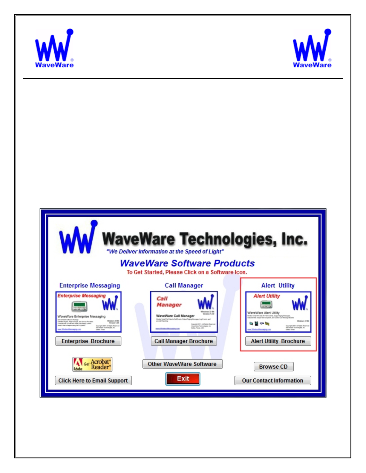
If you Received a WaveWare Software CD, place it into your PC’s CD-Rom Drive and when the CD Auto-Starts,
Click on the “Alert Utility” Icon on the Main Screen. See Fig. 1
Fig. 1 - Main Screen of User Interface of the WaveWare Software CD
Click on the Alert Utility Icon
6
Page 7
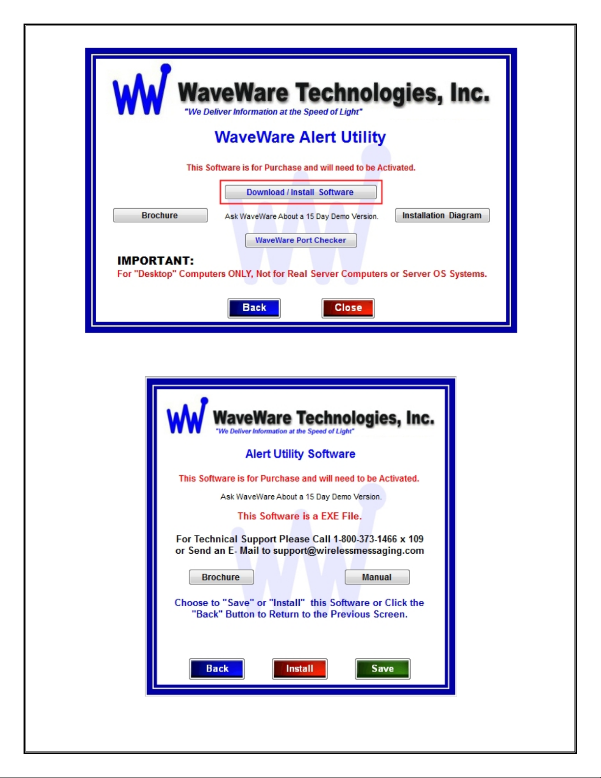
Fig. 2 - Click the “Download / Install Software” Button to Start the Installation Process.
Fig. 3 - Choose to “Save” the Software to a Folder or to Directly “Install” Now.
7
Page 8
Check for Available Com Ports
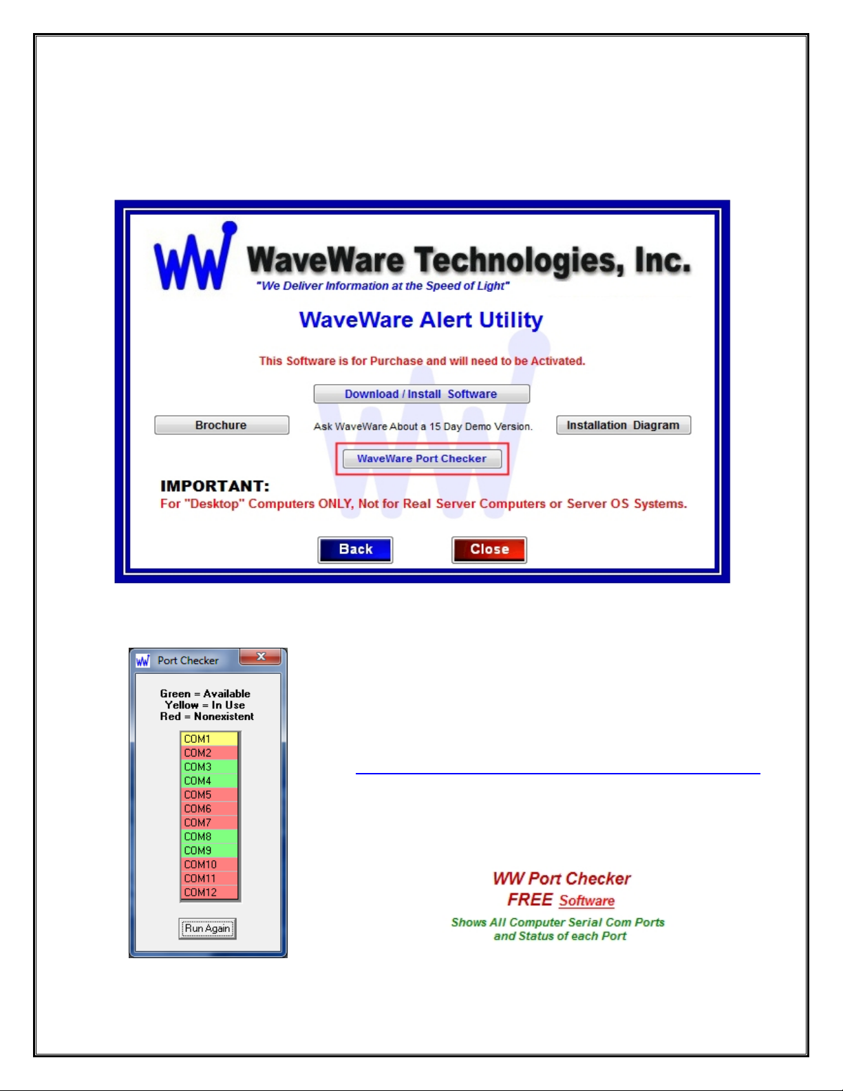
This Utility Software will Search the PC for RS-232 Serial Com Ports and Display the Number of each Port.
If you are not sure of the Status or Availability of the Com Ports installed on the PC…
Click the “WaveWare Port Checker” Button. See Fig.4
Fig. 4 – Click on “WaveWare Port Checker” Button to Run the Port Checker Software
Check the Com Ports
Next: Download Alert Utility from the WaveWare “Website”
NOTE: The Software will Auto Run when you Open it.
You can Check the Ports again, by Clicking the “Run Again” Button.
This Software Utility is Part of the Software CD and is also Available
On-Line on the WaveWare Website, on the same Page as the
Alert Utility Software at the Following Link:
http://www.wirelessmessaging.com/WaveWare_Software.html
Look at the Bottom Left Corner of the Screen for the Software.
Look for:
Click on the word: “Software” as Shown above.
8
Page 9
Download Alert Utility from WaveWare Website
Download the Alert Utility Software from the WaveWare Website and save to a Folder anywhere on the Desktop
PC. Website: http://www.wirelessmessaging.com/wavewaresw.html
Be sure to Download and Save to a Folder to keep for any Future re-installs.
It is highly “Recommended” that you “Keep a Copy” of the Alert Utility Software in a Safe place.
NOTE: Without the Originally Purchased Software “Version”, you will need to “Re-Purchase” the Software.
Installing Alert Utility Software
Go to the Folder where you Saved the Alert Utility Software and Click on the alert_utility_setup.exe.
Then After installing the Software…Proceed with Registering the Software.
Registering/Activating Alert Utility Software
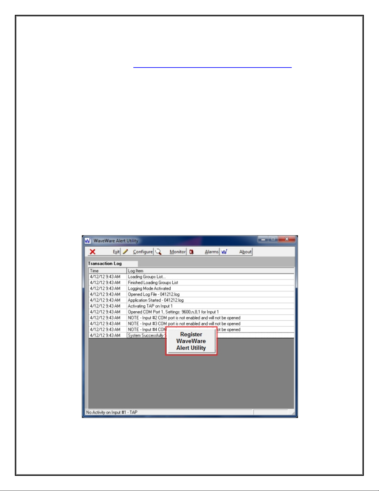
After Installing the Alert Utility Software, Start the Software for the First time.
You should see the “Register Alert Utility” Icon in the Center of the Screen.
Click, on the Register Icon.
See Fig. 5
Fig. 5 – Click the Icon to Start the Registration Process
If the above Screen with the Register Icon is seen, after Clicking the Icon, Jump to Page 9.
If you Do Not see the Register Icon, Please Continue to the next Page to Register the Software.
9
Page 10

On the main “Alert Utility Software” Screen, Click on the “About” Button, as Shown below. See Fig. 6
Fig. 6 - Click the “About” Button to Start the Registration Process
On the Next Screen, Click on the “Registration” Button. See Fig.7
Fig. 7 - Click on the “Registration” Button
Next: Instructions for Registering the Alert Utility Software
10
Page 11
Generating the “Request Key” for Alert Utility Software
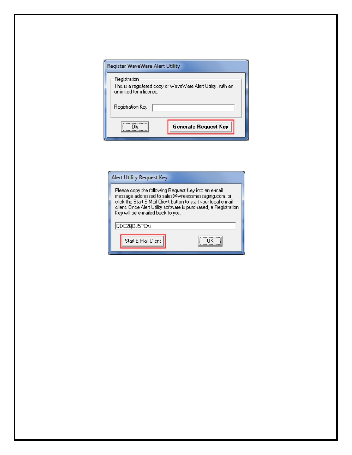
On this Screen, Click the “Generate Request Key” Button. See Fig. 8
Fig. 8 - Click the “Generate Request Key” Button
Follow the Instructions on the Server Request Key Screen to send the “Request Key” to WaveWare. See Fig. 9
Fig. 9 - Click on the “Start E-Mail Client” Button
If you have Internet and Email capability on the PC, Click on the “Start E-Mail Client” Button. See Fig. 9
IMPORTANT NOTE:
The “Activation Key” will ONLY work on the Computer that Generated the Request Key.
Next: Instructions for Sending the Generated Request Key to WaveWare by Email
11
Page 12
Email the “Request Key” for Alert Utility to WaveWare Technologies
After you Click on the “Start Email Client” Button in Fig. 9
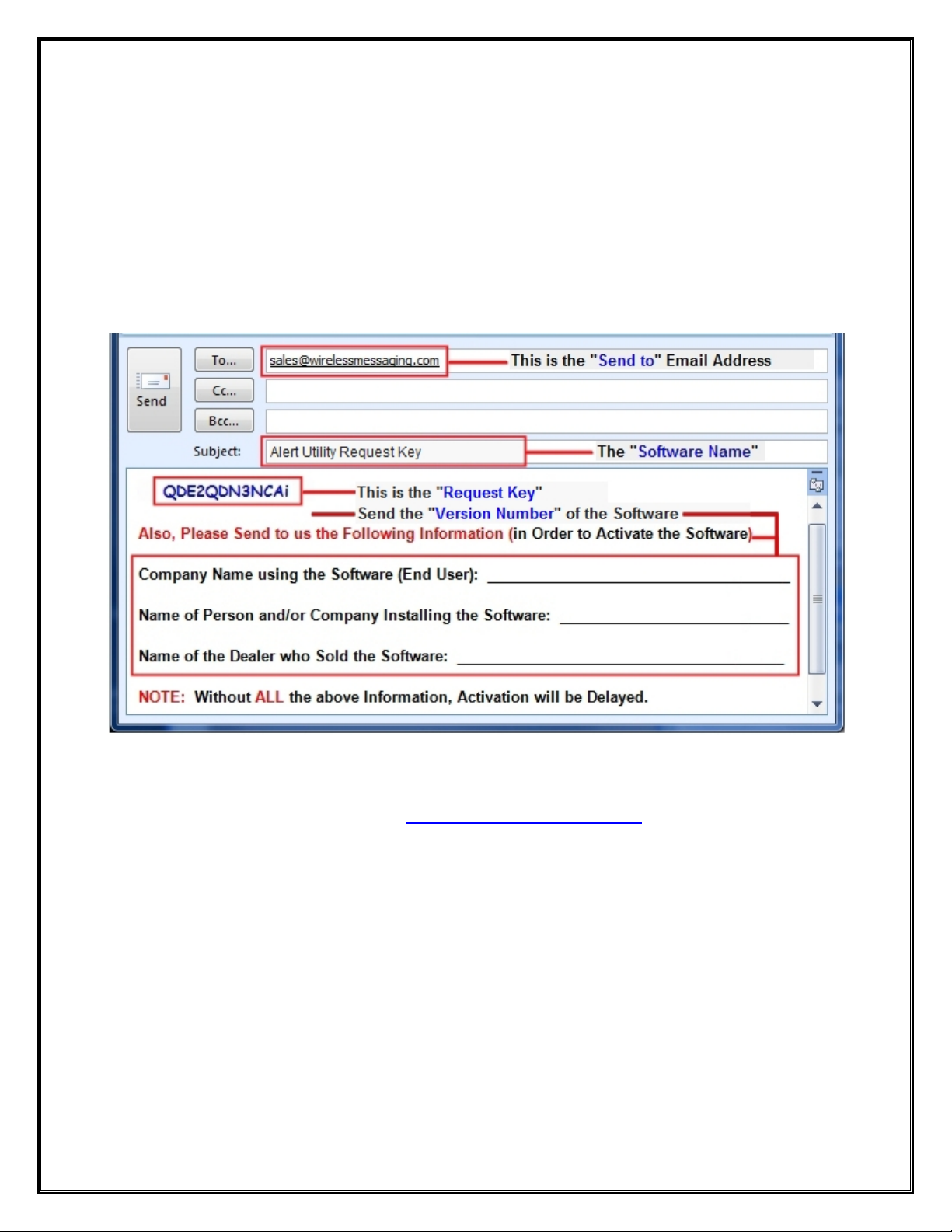
This should start and open an E-mail Client Window with the “Key” in the Body of the E-Mail, and our “Sales”
Email Address in the “To: Window” and “Software Name” in the Subject Line. As shown below in Fig. 10.
If you Do Not have Internet and Email on the Desktop PC, then Copy and Paste the Req uest Key into Notepad or a
Word Document and then Copy that file to a Flash Drive and take to a PC that does have Email capability.
IMPORTANT
Please, be sure to “ADD ALL” of the 4 Required Information Fields to the Email, as shown below. See Fig. 10
Fig. 10 – Send ALL the Above Information
NOTE 1: Include in the Body of the E-Mail: Your Company Name, Contact Name and the Name of the Company
from whom the “Software was Purchased From”, Include the “Version Number” of the Software and send the
E-Mail to us: Sales@WirelessMessaging.com
NOTE 2: Failure to Send All the Required Information will Delay sending the Activation Key. See Fig. 10
Without All the Required Information, No Key will be sent.
Next: Instructions for Activating our Alert Utility Software
12
Page 13
Registering/Activating Alert Utility Software
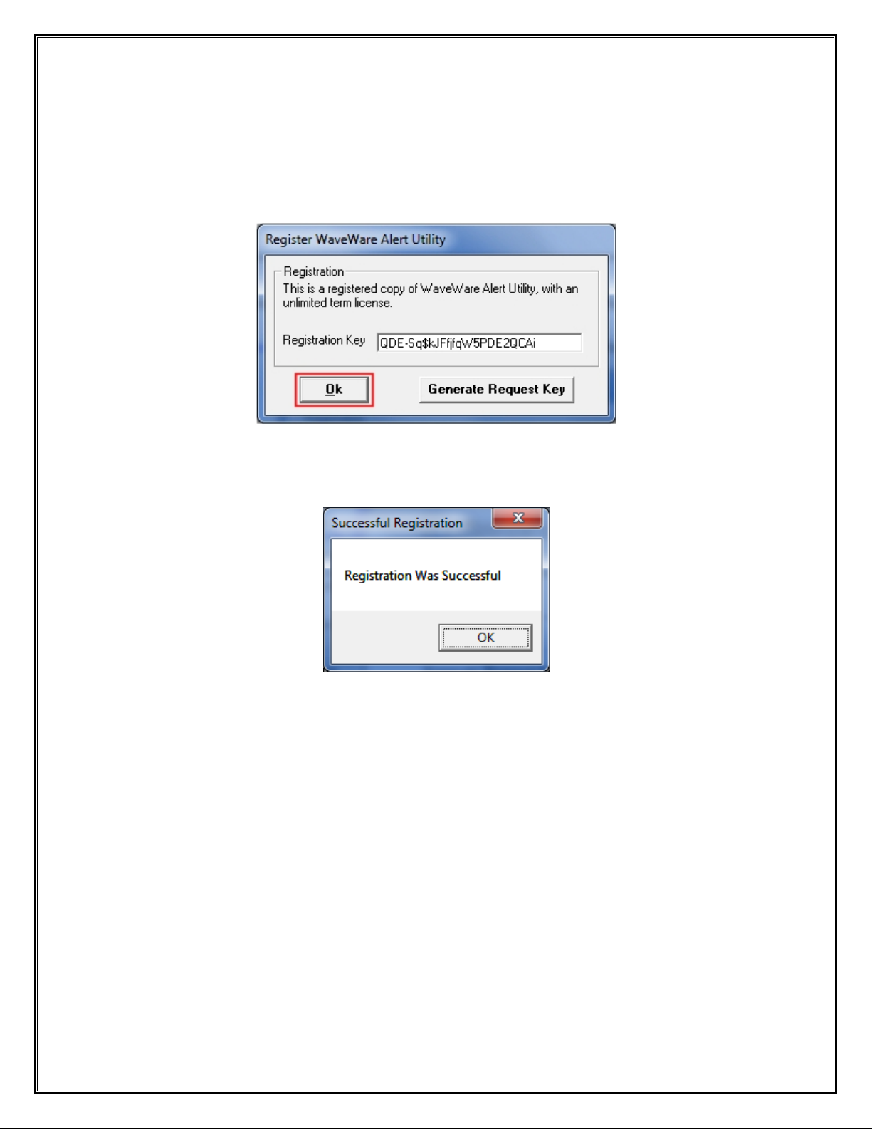
WaveWare will send a Reply Email with the “Registration/Activation Key” for either a Trail Key or Permanent Key.
If you have not received a reply within 30 minutes, please call us at: 1.800.373.1466, and ask for Tech Support.
Copy and Paste the “Activation Key” into the “Registration Key” Field and Click “OK”. See Fig. 11
Fig. 11
You should then see: “Registration Was Successful”. Click “OK”, See Fig. 12
Fig. 12
This Concludes the Registration Process.
If you have any Problems with the Installation or Registration or just have Questions, please Contact the Dealer
from whom you have purchased the Software.
Please Note:
WaveWare Supports our Dealers and our Dealers Support their Customers.
Thank you.
Next: How to Configure Alert Utility Software
13
Page 14
WaveWare Technologies, Inc.
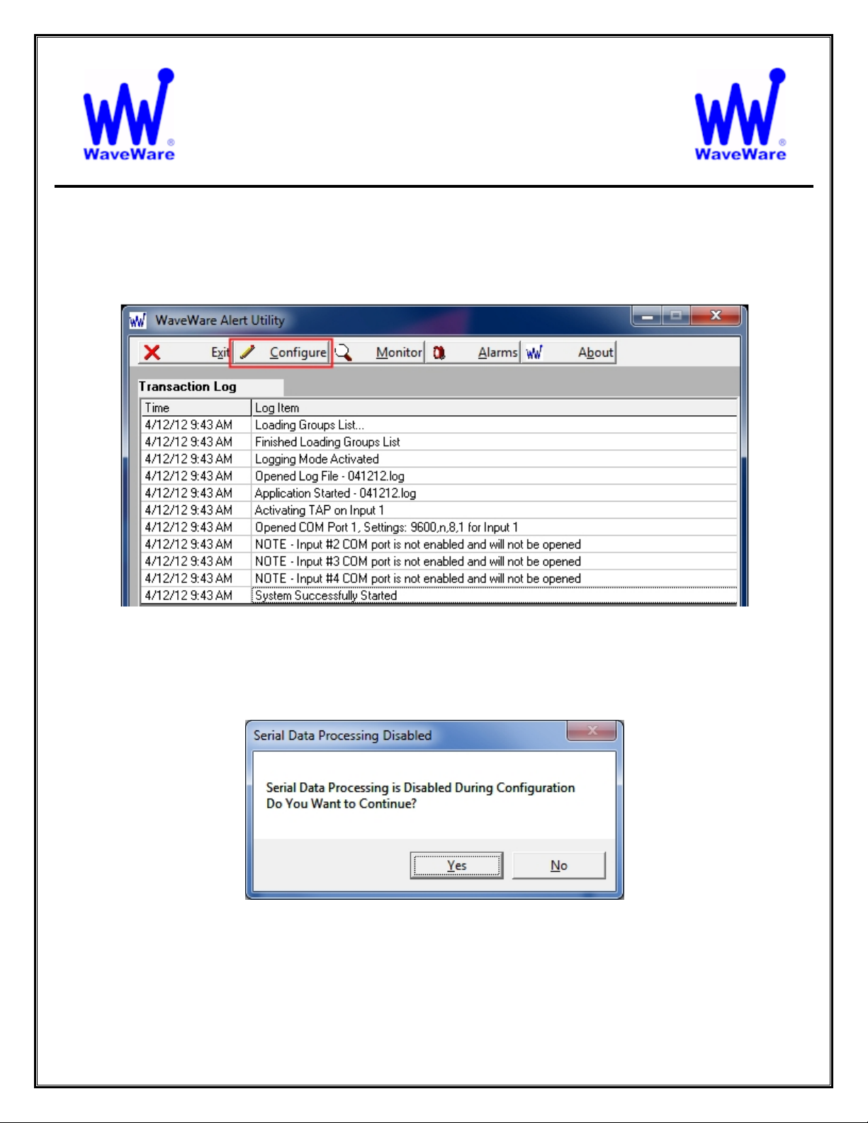
Click on the “Configure” Button to start the Configuration Process. See Fig. 13
“We Deliver Information at the Speed of Light”
Alert Utility Software
Configuring Alert Utility Software
Fig. 13 – Click on the “Configure” Button to Start the Setup of Alert Utility
You will be asked if you are sure, as the system is “Halted” during the Configuration Process. See Fig. 14
Fig. 14 - Click Yes.
Next: Alert Utility Configuration
14
Page 15
General Overview of Configurability
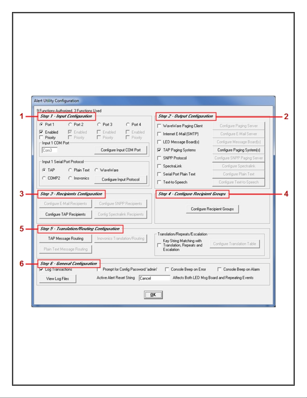
This Screen allows Configuration of Alert Utility in 6 Easy steps. See Fig. 15
Step 1: Selecting and Configuring the “Input Ports” and the Serial Protocols
Step 2: Selecting the Different Output Methods
Step 3: Recipient Configuration
Step 4: Group Recipient Configuration
Step 5: Translation and Escalation Configuration
Step 6: General Configuration
Fig. 15 – Alert Utility Configuration Main Screen
NOTE: While Configuring Step 1 Protocols, Corresponding Configuration Options in Step 5 will be Highlighted as
needed when choosing an Option. For Instance, in Step 1 when you choose “TAP Protocol”, you will see
“TAP Message Routing” in Step 5 become Highlighted and Enable, to be Configured.
The Following Pages will cover each Step giving General Options for the Basic Configuration the Software.
Next: Step 1 – General Com Port Settings and Configuring the “Input Ports” and the Serial “Protocols”
15
Page 16
WaveWare Technologies, Inc.
“We Deliver Information at the Speed of Light”
Alert Utility Software
Input Port Configuration for Alert Utility Software
General Com Port Configuration
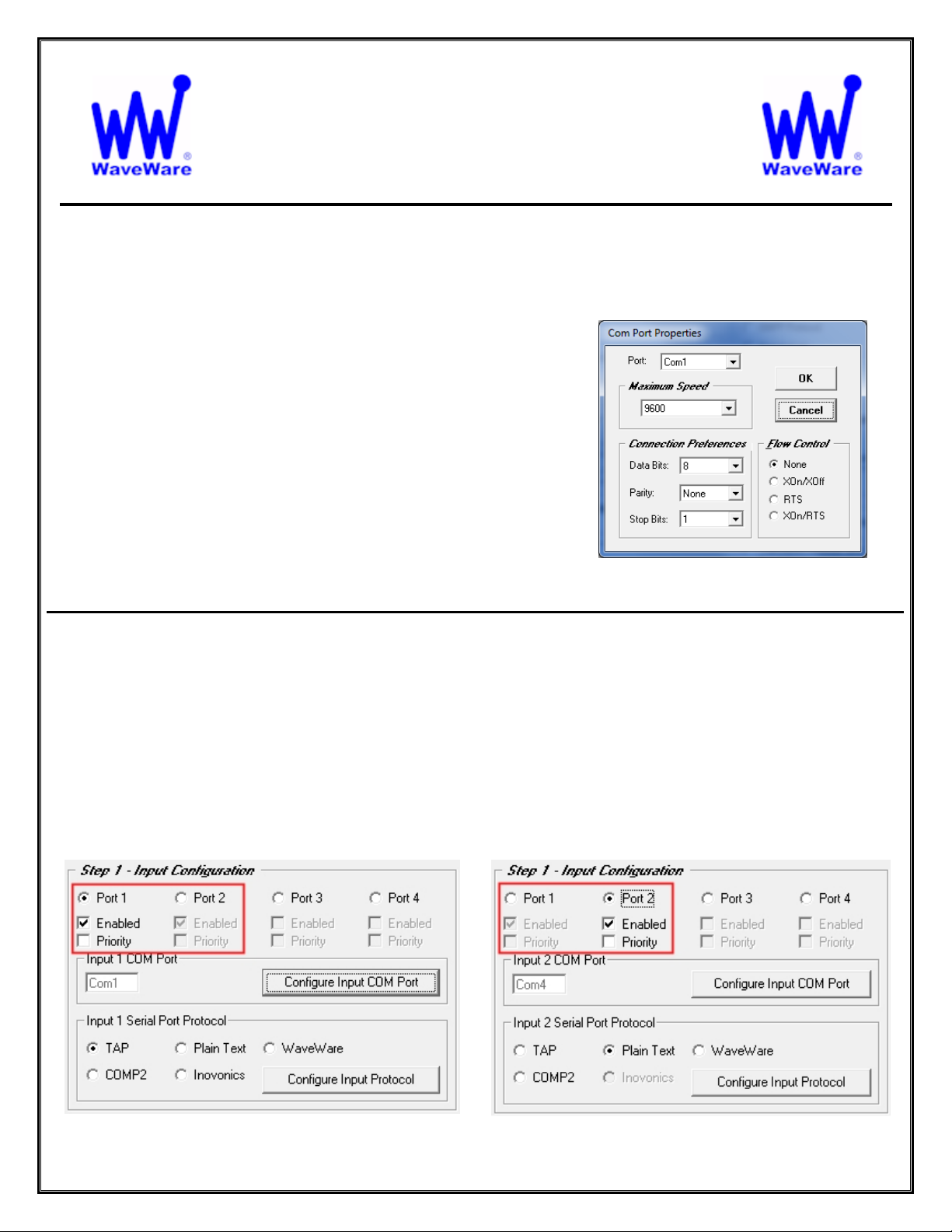
Basic Com Port Settings - Defaults are Shown. See Fig. 16
Port:
o The Com Port Number Assignment
Maximum Speed:
o Serial Port Baud Rate
Connection Preferences:
o Data Bits, Parity and Stop Bits
Flow Control:
o None, XOn/XOff, RTS and XOn/RTS
You may need to Adjust these Settings to meet the Requirements
of each “Host System” that is attached to the Input Port(s).
In Step 1 - Select an “Input Com Port” and Assign an Available Serial Com Port.
Highlight the Com Port you wish to work with by “Clicking” on that Input Port’s Round Button. See Fig. 17A, B
Note: A “Highlighted Port” is a Port that you are configuring, while the “Grayed Out” Port is shown but not able
to be configured until the Port is highlighted.
For each Input Port Enabled, you also choose the Com Port Settings and Protocol for that Input Port.
You may also choose to make that Input Port a “Priority”.
Priority means that any Data coming in on that Input Port will be processed “First”, before Data on other Ports.
Step 1 – Selecting Input Com Ports
Fig. 16
Com Port Properties- Defaults
Fig. 17A
Input 1 Active (Highlighted)
16
Fig. 17B
Input 2 Active (Highlighted)
Page 17
Step 1 – Configuration – Input Protocols – TAP and COMP2
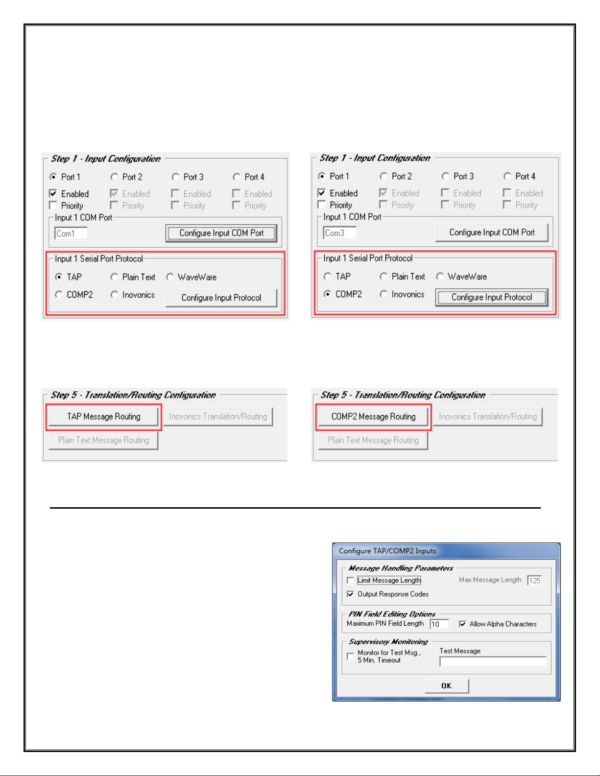
Choose the Protocol you wish to use on an Input Port
Each Input Port can be Configured for any one Protocol: TAP, Plain Text, WaveWare, COMP2 and Inovonics.
Step 1 – TAP and COMP2 Protocols
Fig. 18A
Configure the TAP Input Port and Protocol
Configure the COMP2 Input Port and Protocol
Fig. 18B
Configure the Input Com Port and Protocol, Further Configuration when you get to Step 5. See Fig. 18C and 18D
Fig. 18C
Corresponding Configuration for TAP Protocol
See Page 38
Corresponding Configuration for COMP2 Protocol
Fig. 18D
See Page 42
Step 1 – For TAP and COMP2 Protocol - Click on the “Configure Input Protocol” Button.
Here you can choose:
Message Handling Properties:
o Limit Message Length (Enter Maximum Characters)
o Output Response Codes
PIN Field Editing Options:
o Maximum PIN Field Length, Allow Alpha Characters
Supervisory Monitoring:
o Monitor For Text Message, 5 Minute Time Out
o Enter a Test Message
For the Most Common Default Settings. See Fig. 19
Fig. 19
Defaults for Both TAP and COMP2
17
Page 18
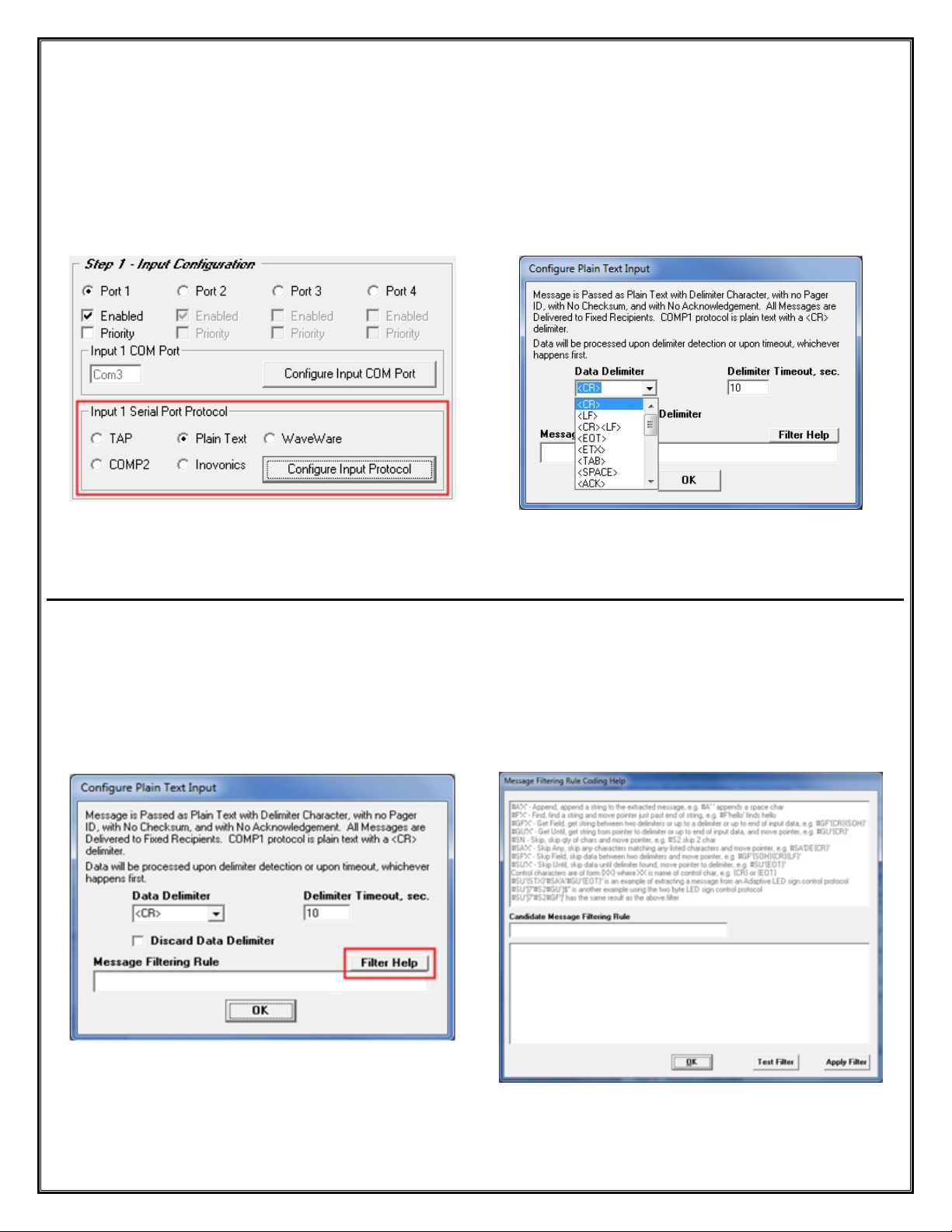
Step 1 – Configuration – Input Protocols – Plain Text
Step 1 – Plain Text Protocol
Click the “Configure Input Protocol” Button to Configure the Plain Text Protocol. See Fig. 20A
Configure Plain Text Protocol with a Data Delimiter and Delimiter Time-out. See Fig. 20B
Fig. 20A - Click “Configure Input Protocol”
Corresponding Configuration for Plain Text Protocol
See Page 39
Fig. 20B
Choose the Data Delimiter, <CR> is Default
Choose Delimiter “Time-Out”, 10 Sec is Default
The Plain Text Protocol Configuration also allows the use of Message Filtering Rules.
Click on the “Filter Help” Button to Open the Coding Help Screen, See Fig. 21A
At the top of the Screen you will find “Coding Help” and at the Bottom of the Screen you write the Code for the
Rule you want use. In the “Candidate Message Filtering Rule” Field you will see the Written Code and you can
test the Rule by Clicking the “Test Filter” Button.
If the Rule is ready, Click the “Apply Filter” Button. See Fig. 21B
Fig. 21A
To Configure Filtering Rules Click on “Filter Help”
Fig. 21B
Configure Filter Rules Screen
18
Page 19

Step 1 – Configuration – Input Protocols – WaveWare and Inovonics
Step 1 – WaveWare and Inovonics Protocol
There are No Input Protocol Configurations for WaveWare and Inovonics. See Fig. 22A and 22B
Configure the Input Com Port and See Step 5 for Further Configuration. See Fig. 23A and 23B
Fig. 22A
Fig. 23A
Corresponding Configuration for WaveWare Protocol
See Page 42
Next: Step 2 – Output Configuration
Fig. 22B
Fig. 23B
Corresponding Configuration for Inovonics Protocol
See Page 40
19
Page 20
WaveWare Technologies, Inc.
Configuring the Outputs for Alert Utility Software
General Overview of Output Configuration Options
“We Deliver Information at the Speed of Light”
Alert Utility Software
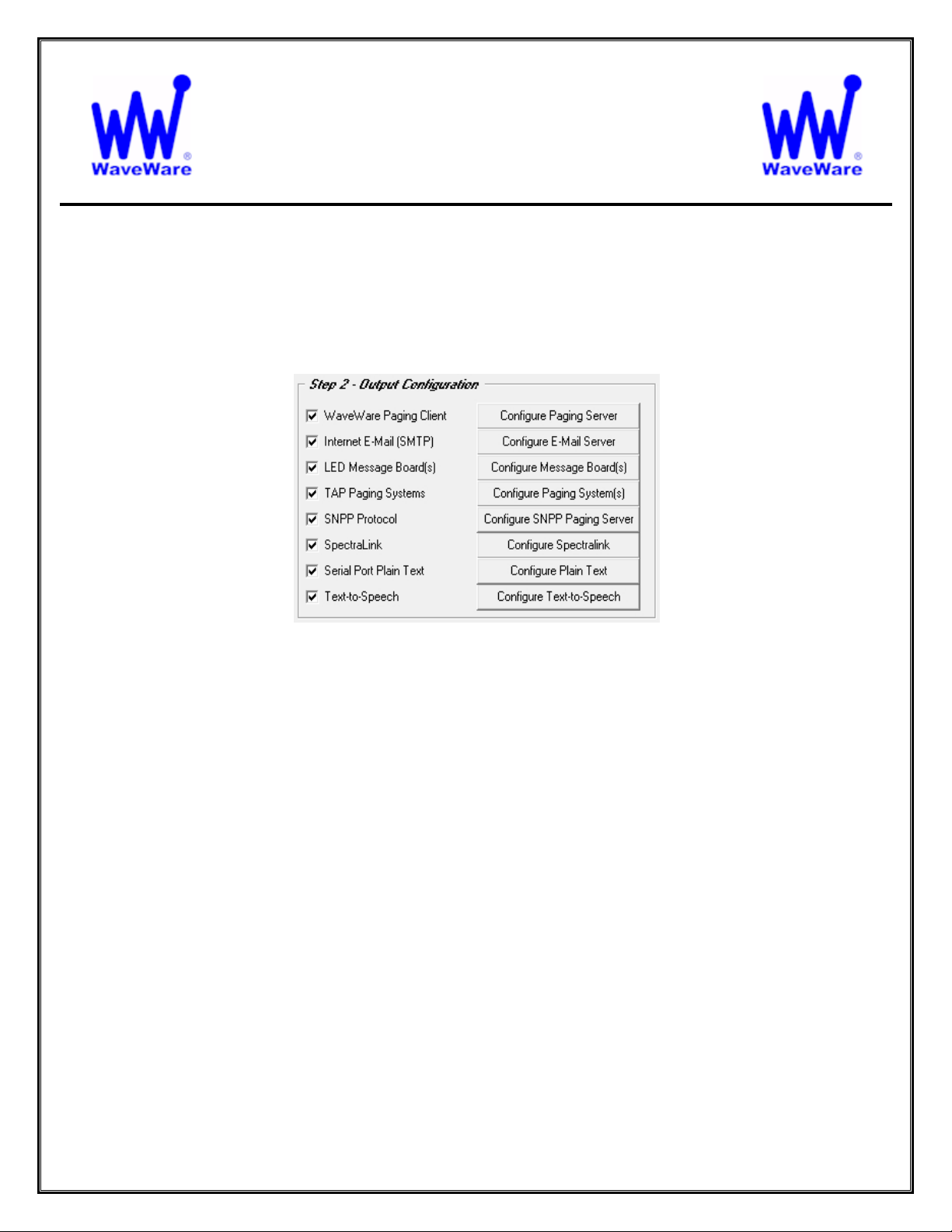
Step 2 – Configuration – Output Methods
Here you may choose one or more Output Methods:
WaveWare Paging Client:
o To Send Messages using the WaveWare Enterprise Messaging Server
Internet Email (SMTP)
o To Send Messages via the Internet Email Server using SMTP Protocol
LED Message Board(s)
o To Send Messages to LED Message Board(s)
TAP Paging System(s)
o To Send Messages to On-Site Paging System(s) using TAP Protocol
SNPP Protocol
o To Send Messages to Wide Area Service Pagers
SpectraLink
o To Send Messages to SpectraLink Phones
Serial Port Plain Text
o To Send Messages using Plain Text
Text-to-Speech
o To Convert Messages from Text into Voice
This Manual will cover all Output Methods, starting with “TAP Paging System(s)”
20
Page 21
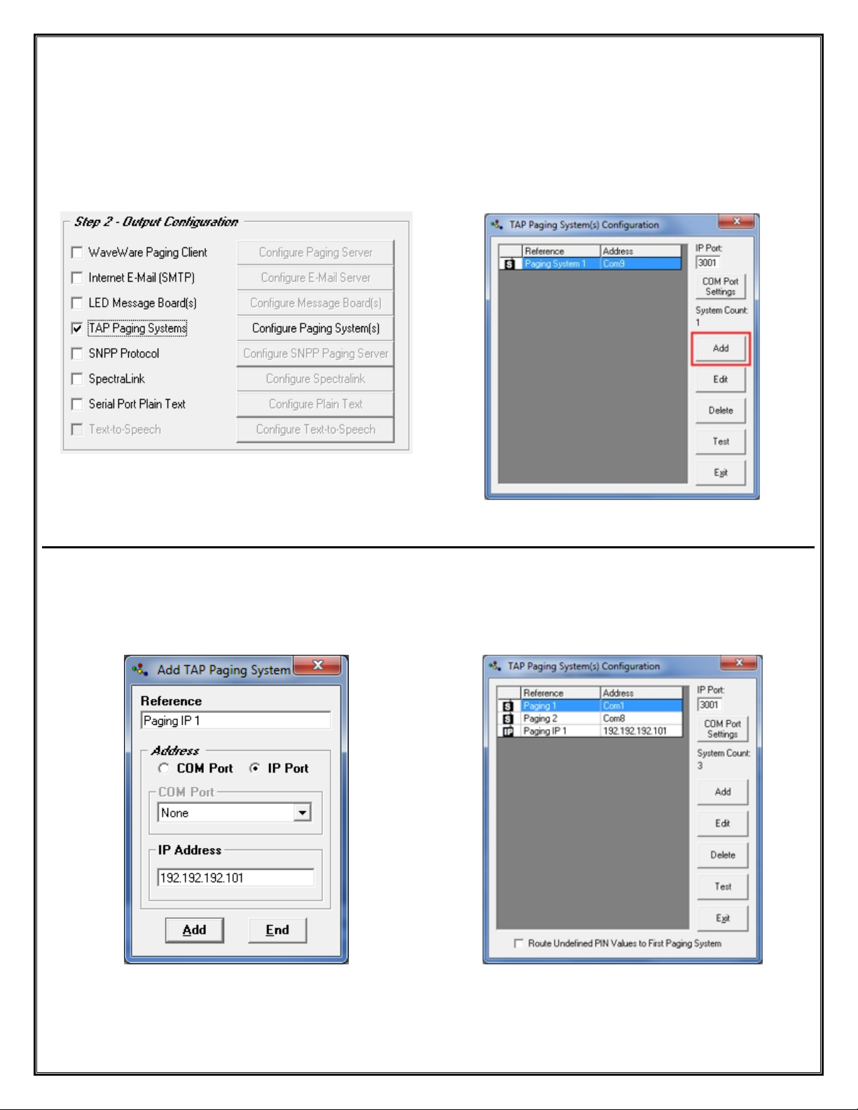
Step 2 – Configuration – Output – TAP Paging System
To use “TAP Paging Systems” for an Output, you will need to Configure the Paging System(s) that will be used
with this Application. To Add a TAP Paging System, Place a Check Mark next to “TAP Paging System(s)” and
then Click on the “Configure Paging System(s)” Button. See Fig. 24
In the TAP Configuration Screen you can Add, Edit, Delete and Test each Paging System Configuration.
Click the “ADD” Button in the Configuration Screen to Add a Paging System. See Fig. 25
Fig. 24 TAP Paging Systems Output
Click on the “Configure Paging System(s)” Button
Fig. 25
Tap Paging System Configuration Screen
Enter a Description to be used as a “Reference”.
Enter a “Com Port Number” or an “IP Address” that will be Assigned to the Paging System. See Fig. 26
Highlight the Configuration you want to Edit, Delete or Test.
If assigning a Com Port you can also configure the Com Port Settings for each system. See Fig. 27
Fig. 26
Add a TAP Paging System using an IP Address
Next: Step 2 – Output Configuration – Internet E-Mail (SMTP)
Fig. 27
Multiple Paging System Output Assignments
21
Page 22

Step 2 – Configuration – Output – Internet E-Mail (SMTP)
If using Internet E-Mail (SMTP) for Output, Click on the “ See Fig.
To use “Internet E-Mail” for an Output, you will need to Configure the Internet Email Server that will be used with
this Application. To Add an Internet Email Server, Place a Check Mark next to “Internet E-Mail (SMTP)” and then
Click on the “Configure E-Mail Server” Button. See Fig. 28
In the Configure E-Mail Output Screen, Fill-in the “SMTP Host”, (You may need to get this Information from the IT
Dept) and the “From Name” and “From Email Address”. If you want to use the “Message in Subject Line” Option,
then you will need to Fill-in the “Subject” Field. You also have the Options of the Email being “Priority” and to
use “Authentication” with User ID and Password. See Fig. 29
Fig. 28 Internet E-Mail (SMTP)
Click on the “Configure E-Mail Server” Button
To Test the Mail Server, Fill-in the “To: Address” Field and Click on the “Test Mail Server” Button. See Fig. 29
You will get one of the Results as shown. See Fig. 30A and 30B
Fig. 30A
If you see this Screen, please check your Information
and configuration and try again.
Next: Step 2 – Output Configuration – WaveWare Paging Client
Fig. 29
Configure Email Output
Fig. 30B
If you see this Screen, you are ready for the next Step.
22
Page 23

Step 2 – Configuration – Output – WaveWare Paging Client
To use a “WaveWare Paging Client” for an Output, you will need to Configure the Enterprise Paging Server that
will be used with this Application. To Add a Paging Client, Place a Check Mark next to “WaveWare Paging Client”
and then Click on the “Configure Paging Server” Button. See Fig. 31
Fig. 31 WaveWare Paging Client
Click on the “Configure Paging Server” Button
Enter the “IP Address” of the Enterprise Paging Server and Click OK. See Fig. 32
Fig. 32
Configure Server IP Address
Next: Step 2 – Output Configuration – SpectraLink
23
Page 24

Step 2 – Configuration – Output – SpectraLink
To use SpectraLink for an Output, you will need to Configure the SpectraLink that will be used with this
Application. To Add a SpectraLink as an Output, Place a Check Mark next to “SpectraLink” and then Click on the
“Configure SpectraLink” Button. See Fig. 33
Enter the “Com Port” attached to the SpectraLink System and Configure the Number of “Retries and Delay Time”
for Busy and No Answer. See Fig. 34
Fig. 33 SpectraLink
Click on the “Configure SpectraLink” Button
Next: Step 2 – Output Configuration – LED Message Boards
Fig. 34
Configure The Com Port and the Number of Retries
for “Busy” and “No Answer” with “Delay” Times
24
Page 25

Step 2 – Configuration – Output – LED Message Board(s)
To use LED Message Board(s) for an Output, you will need to Configure the Message Board(s) that will be used
with this Application. To Add a LED Message Board, Place a Check Mark next to “LED Message Board(s)” and
then Click on the “Configure Message Board(s)” Button. See Fig. 35
Fig. 35 LED Message Boards
Click on the “Configure Message Boards” Button
In the “Configure Message Board(s)” screen, you have these options:
There are Three Fields for Configuration for use with a LED Message Board(s):
Output Options
Message Display Configuration
Maintenance
Output Options:
For Reference, See Fig. 36
To use as a “Wired Connection”
o Choose the Com Port that the LED Message Board is attached to and Configure the Port
To use as a “Wireless Connection” using a Paging Data Receiver, for Delivery of the Message to the Board(s)
o This Option allows you to Send a Message to the Paging Data Receiver (PDR) that is atta ched to the
LED Message board(s), via the Paging System
To use “Message Routing”
o This Option allows you to Associate a PIN Number to a Sign’s Address
Wired - Configure Com Port
PDR–Configure PIN– Message Routing
Fig. 36 Output Options
25
Table
Page 26
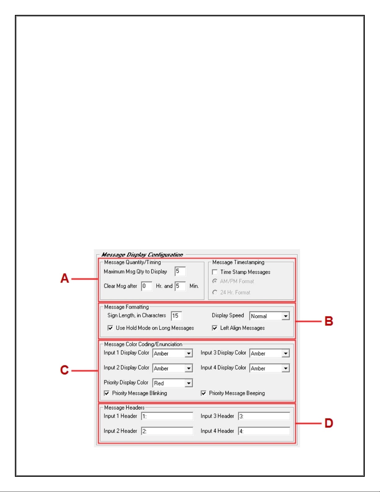
Message Display Configuration:
For Reference, See Fig. 37
A - Message “Quantity and Timing”
o Choose the Number of Total Messages that can be Shown on the Display
o Choose How long to Display the Message(s) - (This is a Global Setting)
A - Message “Time Stamping”
o Choose this Option to Add a Time Stamp to the Message being Displayed
o Choose between AM/PM Format or 24 Hr. Format
B - Message “Formatting”
o Enter the Number of Total Characters the Sign can Display (Match the Sign’s Capability)
o Choose the Speed of which the Message Scrolls across the Sign
o Choose to use “Hold Mode” and to “Left Align” Messages.
C - Message “Color Coding and Enunciation”
o Choose the Colors for up to 4 Inputs for the Message being Displayed
o Choose the Color for “Priority” Messages
o Choose to have the Priority Message Blink and / or to have the Sign Beep
D - Message “Headers”
o Choose this Option to Add a Header to a Message on a given Input
Fig. 37 Message Display Configuration
26
Page 27

Maintenance:
For Reference, See Fig. 38
Here you can:
o Choose to Test the Message Board(s)
o Clear the Message Board(s) of Messages
o Choose if you want to use Supervise the Wired Connection
Fig. 38 Maintenance
Next: Step 2 – Output Configuration – SNPP Protocol
27
Page 28

Step 2 – Configuration – Output – SNPP Protocol
To use SNPP Protocol for an Output, you will need to Configure the SNPP Paging Server that will be used with
this Application. To Add a SNPP Protocol Output Place a Check Mark next to “SNPP Protocol” and then Click on
the “Configure SNPP Paging Server” Button. See Fig. 39
Enter the Wide Area Service Provider’s SNPP Server Information into the Configure SNPP Server Screen.
Test the SNPP Server Configuration by Clicking on the “Test SNPP Server” Button. See Fig. 40
Fig. 40 Enter SNPP Server Information - Test
Fig. 39 SNPP Protocol
Type a “Message” and a “Pager PIN Number ” and Click OK to send a Test Message to a Pager. See Fig. 41
If the Test Failed, Check the Server Information and PIN Number and Retest. See Fig. 42
Fig. 41
Enter Message and PIN Number
Check Information and Retry Test
Fig. 42
When Successful you will get the Test Message on the Pager.
Next: Step 2 – Output Configuration – Plain Text
28
Page 29
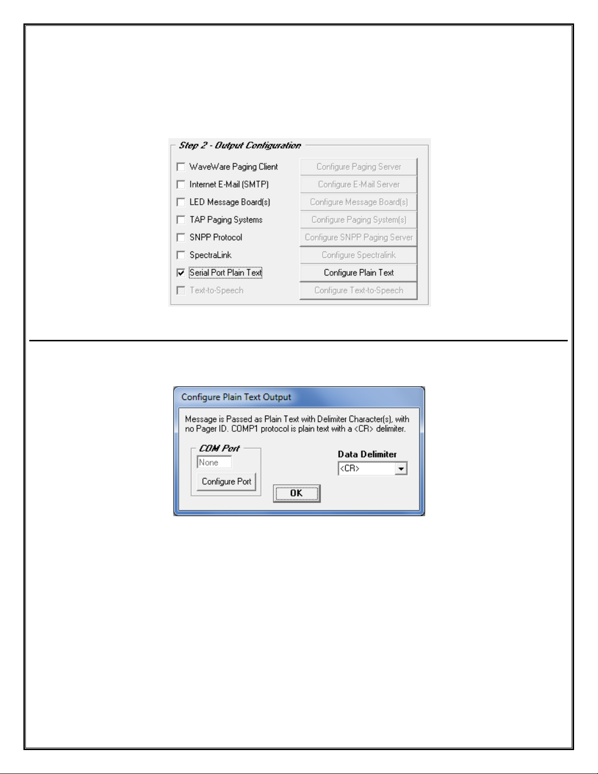
Step 2 – Configuration – Output – Plain Text
To use the Serial Port Plain Text for an Output, you will need to Configure the Plain Text that will be used with
this Application. To Add Serial Port Plain Text, Place a Check Mark next to “Serial Port Plain Text” and then Click
on the “Configure Plain Text” Button. See Fig. 43
Fig. 43 Plain Text
In the “Configure Plain Text Output” Screen, Choose the “Com Port” and “Data Delimiter ”. See Fig. 44
Fig. 44 Choose Com Port and Data Delimiter
Next: Step 2 – Output Configuration – Text-to-Speech
29
Page 30
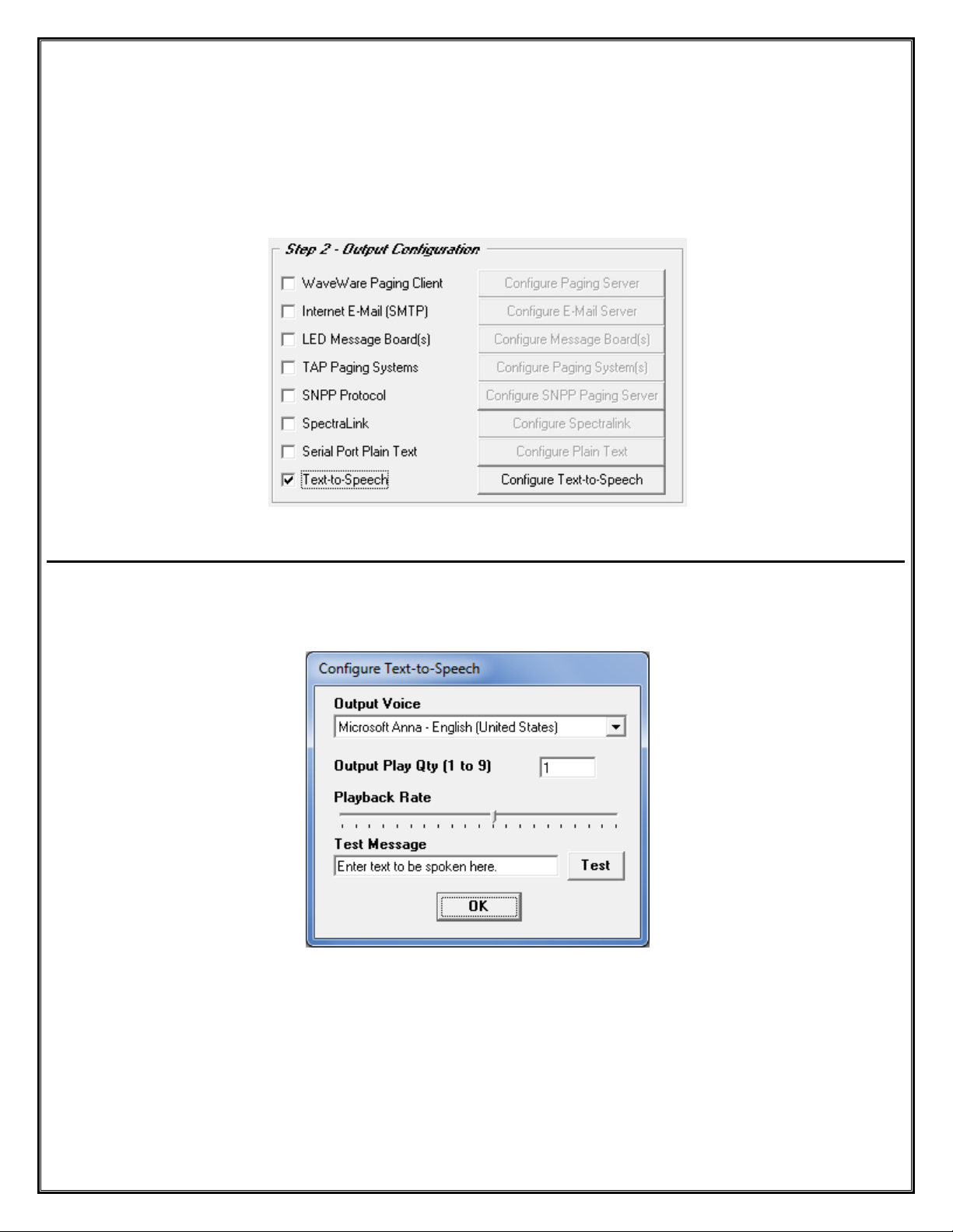
Step 2 – Configuration – Output – Text-to-Speech
NOTE: The “Text-to-Speech” Output is an Additional Purchase
To use the Text-to-Speech for an Output, you will need to Configure the Text-to-Speech Engine which will be
used with this Application. To Add a Text-to-Speech Output, Place a Check Mark next to “Text-to-Speech” and
then Click on the “Configure Text-to-Speech” Button. See Fig. 45
Fig. 45 Text to Speech
In the “Configure Text-to-Speech” Screen, Choose the “Output Voice”, “Output Play Qty” and “Playback Rate”.
You may also check the Speech Settings by Entering a Test Message and click the “Test” Button. See Fig. 46
Fig. 46 Configure Text to Speech Options
Requires Speakers attached to the PC
Next: Step 3 – Recipient Configuration – Overview
30
Page 31
WaveWare Technologies, Inc.
“We Deliver Information at the Speed of Light”
Configuring the Recipient Lists for Alert Utility Software
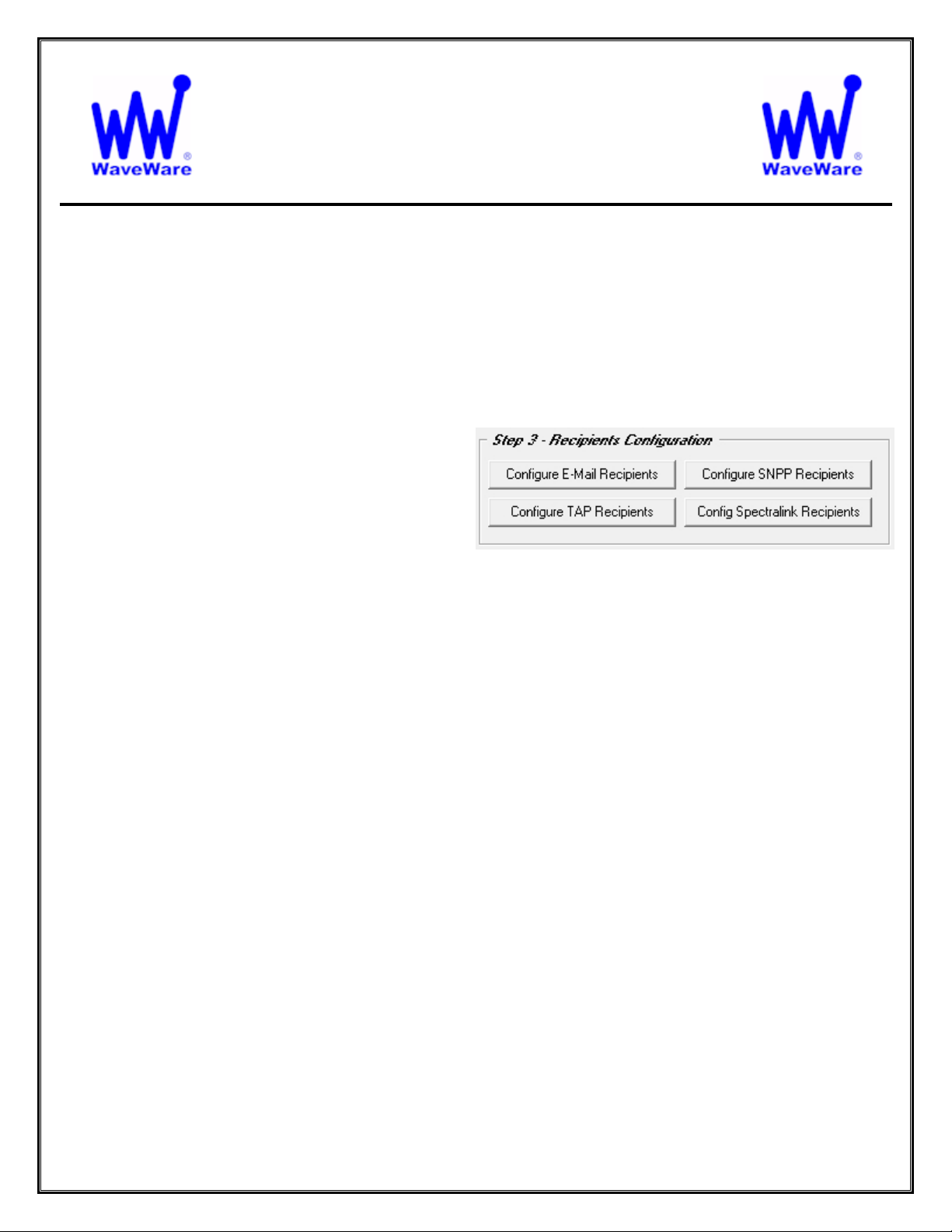
General Overview of Recipients Configuration
For Reference, See Fig. 47
The Recipient Configuration Options are:
Configure E-Mail Recipients:
o For use with Step 2 - “Internet E-Mail (SMTP)”
Configure SNPP Recipients:
o For use with Step 2 – “SNPP Protocol”
Configure TAP Recipients:
o For use with Step 2 – “TAP Paging System(s)”
Configure SpectraLink Recipients:
o For use with Step 2 – “SpectraLink”
This Manual will cover all 4 Recipient Configurations, starting with “TAP Recipients”
Next: Step 3 – Recipient Configuration – TAP Recipients
Alert Utility Software
Step 3 – Recipient Configuration
31
Fig. 47
Recipients Configuration Screen
Page 32
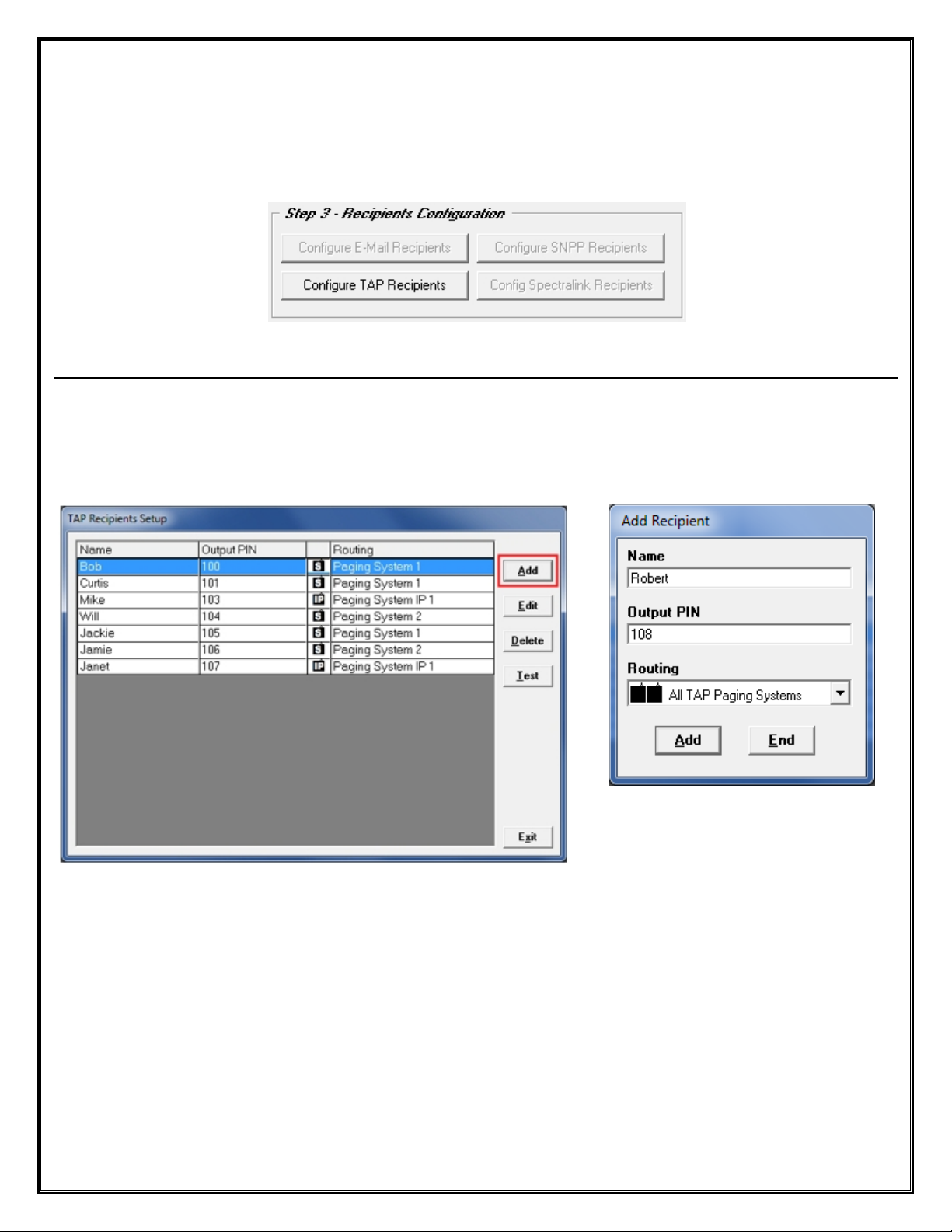
Step 3 – Recipient Configuration – TAP Recipients
To Setup a TAP Paging System for an Output, Click on the Button labeled “Configure TAP Recipients”.
See Fig. 48
Fig. 48
Configure TAP Recipients
To Add a Recipient, Click the “Add” Button in the TAP Recipients Setup Screen. See Fig. 49
Enter the “Name and the Output PIN” for a Recipient and click “Add”.
Under “Routing” Choose the Paging System to be used with this Recipient. See Fig. 50
Fig. 49
TAP Recipient Setup List – Add Recipient
Next: Step 3 – Recipient Configuration – E-Mail Recipients
Fig. 50
Add TAP Recipient
32
Page 33

Step 3 – Recipient Configuration – Email Recipients
To use an E-Mail Recipient for an Output, you will need to Add E-Mail Recipients by Clicking on the
“Configure E-Mail Recipients” Button. See Fig. 51
Fig. 51
Configure E-Mail Recipients
To Add an Email Recipient Click the “Add” Button in the E-Mail Recipients Setup Screen. See Fig. 52
Enter the “Name” and E-Mail “Address” of the Recipient and Click the “Add” Button. See Fig. 53
Add Email Recipient
Fig. 53
Fig. 52
E-Mail Recipient Setup List – Add Recipient
Next: Step 3 – Recipient Configuration – SNPP Recipients
33
Page 34
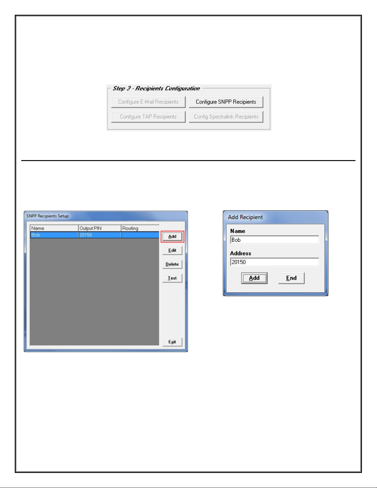
Step 3 – Recipient Configuration – SNPP Recipients
To Setup a SNPP Recipient for an Output, Click on the button labeled “Configure SNPP Recipients”.
See Fig. 54
Fig. 54
Configure SNPP Recipients
To Add a Recipient, While in the Configure Recipient Setup Screen
Click the “Add” Button. See Fig. 55A
Enter the “Name and E-Mail Address” of the Recipient. See Fig. 55B
Fig. 55B Add Recipient
Fig. 55A
SNPP Recipients Setup - Add
Next: Step 3 – Recipient Configuration – SpectraLink Recipients
34
Page 35
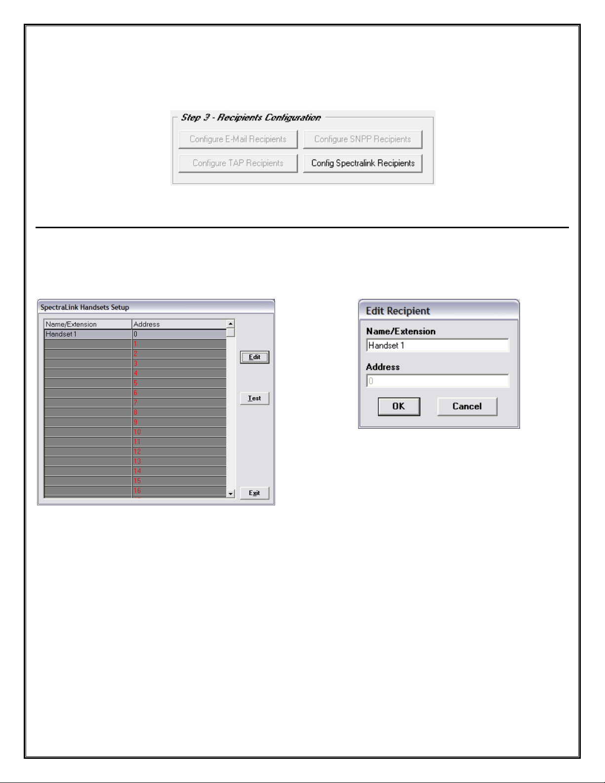
Step 3 – Recipient Configuration – SpectraLink Recipients
To Setup a SpectraLink Recipient for an Output, Click on the Button labeled “Configure SpectraLink Recipients”.
See Fig. 56
Fig. 56
Configure SpectraLink Recipients
In the “SpectraLink Handsets Setup” Screen, Highlight a Line and Click on the “Edit” Button. See Fig. 57
Enter the “Name/Extension” of the Recipient along with the “Address” assignment an d Click OK. See Fig. 58
Fig. 58 Edit Recipient
Fig. 57 SpectraLink Setup - Click “Edit” Button
Next: Step 4 – Configure Recipient Groups
35
Page 36

Configure Recipient Groups for Alert Utility Software
To Setup Recipient Groups Click on the Button labeled “Configure Recipient Groups”. See Fig. 59
WaveWare Technologies, Inc.
“We Deliver Information at the Speed of Light”
Alert Utility Software
Step 4 –Configuration of Recipient Groups
Fig. 59 Configure Recipient Groups
To Add a Group Click on the “Add” Button. Then Select the “Recipient(s)” to be in the Group. See Fig 60A, 60B
Fig. 60A Click the “Add” Button to Add a New Group, Then Click the “Recipients” to Add them to the Group
Fig. 60B Clicking on a Name in the “All Recipients” List will Add the Recipient to the “Highlighted” Group
Note: Deselect a Recipient from a Group by Clicking on a “Listed Recipient” in the “All Recipients” List.
36
Page 37

WaveWare Technologies, Inc.
“We Deliver Information at the Speed of Light”
Configuring Translation / Routing for Alert Utility Software
Step 5 – Translation / Routing Configuration - Overview
Translation/Routing Configurations for:
TAP Message Routing:
o For use with Step 1 - “TAP Input Protocol”
See Fig. 61A
COMP2 Message Routing:
o For use with Step 1 – “COMP2 Input Protocol”
See Fig. 61B
WaveWare Message Routing:
o For use with Step 1 – “WW Input Protocol”
See Fig. 61C
Inovonics Translation/Routing:
o For use with Step 1 - “Inovonics Input Protocol”
See Fig. 61D
Plain Text Message Routing:
o For use with Step 1 – “Plain Text Input Protocol”
See Fig. 61E
This Manual will cover all 5 Translations/Routing Configurations, starting with “TAP Message Routing”
Next: Step 5 – Translation / Routing Configuration – TAP Message Routing
Alert Utility Software
Fig. 61A
Fig. 61B
Fig. 61C
Fig. 61D
Fig. 61E
37
Page 38

Step 5 – Translation / Routing Configuration – TAP Message Routing
To Configure TAP Message Routing Click on the Button labeled “Configure TAP Message Routing”. See Fig. 62
Fig. 62
NOTE: TAP, COMP2 and WaveWare Message Routing are All Configured within the sam e Screen.
For “Translation/Repeats/Escalation” Information: See Page: 43
Click the “Add” Button to Add a Recipient/Group. See Fig. 63
Click the Arrow for a Dropdown List of Recipients and Groups to be Added to the Routing List. See Fig. 64
Enter the “Input PIN” Associated with the “Recipient” and Check the Box, if Priority. See Fig. 65
Fig. 64 Click the “Arrow” Button
Fig. 63
Click the “Add” Button
Next: Step 5 – Translation / Routing Configuration – Plain Text Message Routing
38
Fig. 65 Enter PIN Number
Page 39
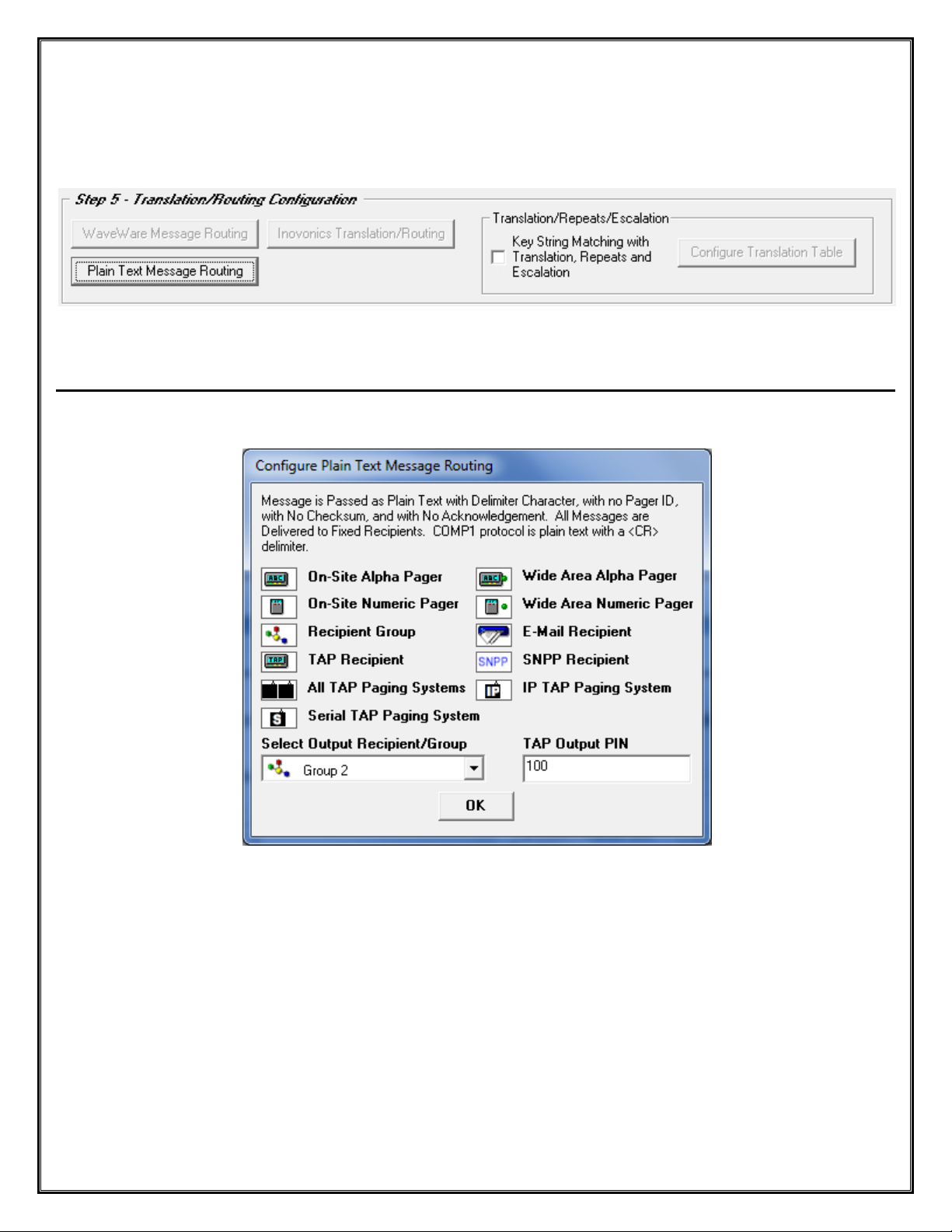
Step 5 – Translation / Routing Configuration – Plain Text Message Routing
To Configure Plain Text Message Routing, Click the Button labeled “Plain Text Message Routing”. See Fig. 66
Fig. 66 Plain Text Message Routing
Note: For “Translation/Repeats/Escalation” Information: See Page: 43
Select the “Output Recipient / Group” and the “TAP Output PIN” Number. See Fig. 67
Fig. 67
Configure Plain Text Message Routing
Next: Step 5 – Translation / Routing Configuration – Inovonics Message Translation / Routing
39
Page 40
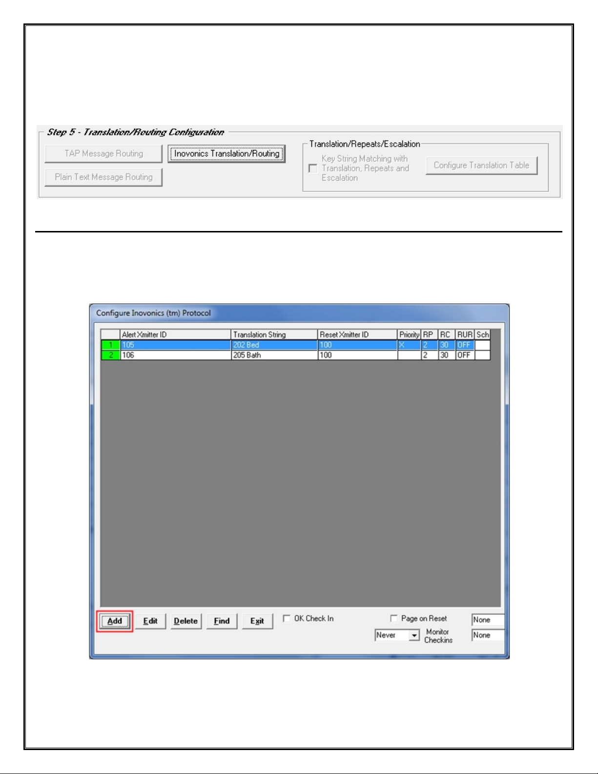
Step 5 – Translation / Routing Configuration – Inovonics Translation / Routing
To Configure Inovonics Translation / Routing, Click the Button labeled “Inovonics Translation / Routing”.
See Fig. 68
Fig. 68 Inovonics Translation / Routing
Click the “Add” Button to Configure the Alert Transmitters ID and Translation Strings. See Fig. 69
Also Configure the Repeats, Repeats Cycle Times, Repeat until Reset, Set as Priority and Scheduling as
Required. See Fig. 70 (Next Page)
Fig. 69 Configure Inovonics
Next: Step 5 – Translation / Routing Configuration – Add Alert Transmitter / Translation String
40
Page 41
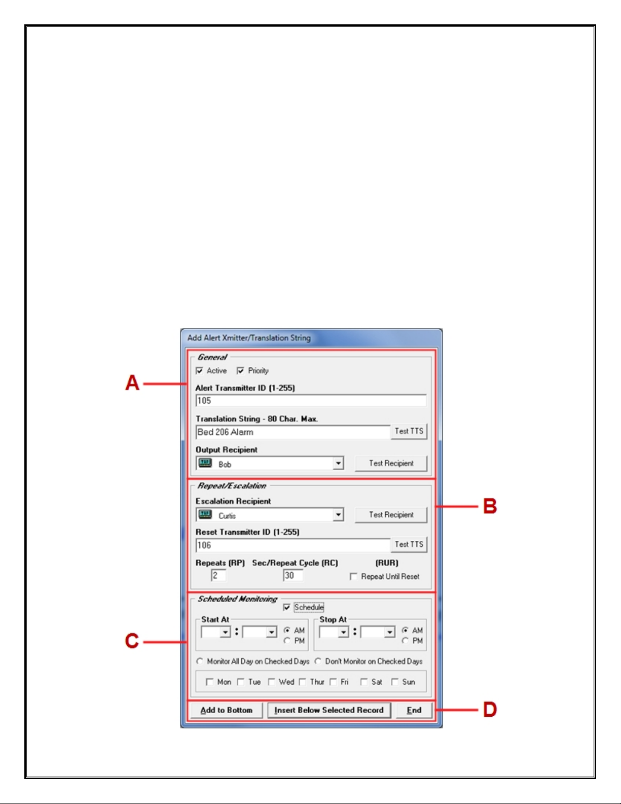
For Reference, See Fig. 70 (Below)
A - General
o Check if Alert is Active and if Priority
o Enter Alert Transmitter ID
o Enter the Translation String
o Choose the Output Recipient
B – Repeat / Escalation
o Choose the Escalation Recipient
o Enter the Reset Transmitter ID
o Enter the Number of Repeats, Repeat Cycle time and Check Box for Repeat Until Reset, if Required
C – Scheduled Monitoring
o Check Schedule Box and Enter the “Start At” and “Stop At” Times
o Choose Which Days of the Week to be Monitored
D – Where to Add the Record
o Choose to Add the New Record to Bottom of List, Insert Below the Highlighted Record or to Close Screen
Fig. 70 Add Alert Transmitter / Translation String
41
Page 42

Step 5 – Translation / Routing Configuration – WaveWare Message Routing
Fig. 71
Step 5 – Translation / Routing Configuration – COMP2 Message Routing
Fig. 72
NOTE: For Information on either WaveWare and COMP2 Message Routing, Refer to Page: 37
Next: Step 5 – Translation / Repeats / Escalation – Key String Matching – Configure Translation Table
42
Page 43
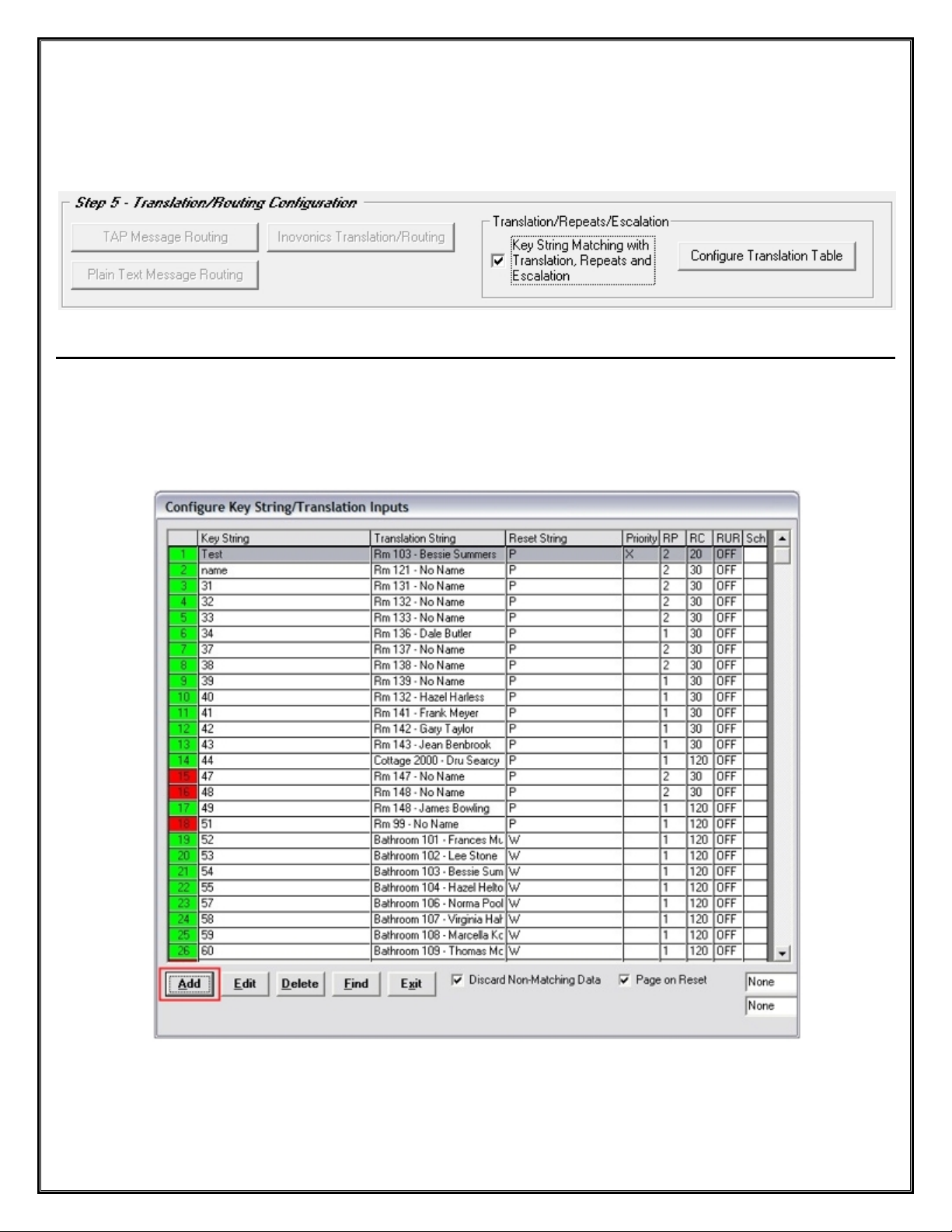
Step 5 – Translation / Repeats / Escalation – Configure Translation Table
To Configure Key String Matching for Translations / Repeats and Escalations Check the Box, then Click the
Button labeled “Configure Translation Table”. See Fig. 73
Fig. 73 Translation / Routing Configuration
Click the “Add” Button to Configure the Key String / Translation Inputs. See Fig. 74
Also Configure the Repeats, Repeats Cycle Times, Repeat until Reset, Set as Priority and Scheduling as
Required. See Fig. 75 (Next Page)
Fig. 74 Configure Key String / Translation Inputs
Next: Step 5 – Translation / Routing Configuration – Add Key Strings and Translation Inputs
43
Page 44

For Reference, See Fig. 75 (Below)
A - General
o Check if Alarm is Active and if Priority
o Enter the Key String
o Enter the Translation String
o Choose the Output Recipient
B – Repeat / Escalation
o Choose the Escalation Recipient
o Enter the Reset String
o Enter the Number of Repeats, Repeat Cycle time and Check Box for Repeat Until Reset, if Required
C – Scheduled Monitoring
o Check Schedule Box and Enter the “Start At” and “Stop At” Times
o Choose Which Days of the Week to be Monitored
D – Where to Add the Record
o Choose to Add the New Record to Bottom of List, Insert Below the Highlighted Record or to Close Screen
Fig. 75 Add Key / Translation Strings
44
Page 45

WaveWare Technologies, Inc.
“We Deliver Information at the Speed of Light”
Alert Utility Software
Configuring Alert Utility Software
Step 6 – General Configuration
Fig. 76 General Configuration
For Reference, See Fig. 76
Here you can Choose General Options:
To Log Transactions:
o For creating a Log of All Transactions on a Daily Basis. Starts a New Log at Midnight.
To Prompt for a Configuration Password – The Password is “admin”
o To Only Allow Personnel with Admin Privileges to have Access to the Configurability of Alert Utility
To have a Console Beep on “Error”
o On any Error the Console will Beep
To have a Console Beep on “Alarm”
o For any Alarm the Console will Beep
For Setting a globally assigned Active Alert Reset String
o Enter the Word(s) to be used as a Reset String for all active alerts configured in Step 5 (p. 43).
To View All Log Files
o Click Button to Open Folder to View All Existing Logs
Next: Monitor – View Serial Port Activity
45
Page 46

WaveWare Technologies, Inc.
Monitor Serial Port Activity in Alert Utility Software
To Open the Minitor Window, Click on the Button labeled “Monitor”. See fig. 77
“We Deliver Information at the Speed of Light”
Alert Utility Software
Fig. 77 Main Screen – Click the “Monitor” Button
Fig. 78 Monitor Serial Port Activity Window
In the Monitor Window View you can:
Monitor All Serial Activity
Choose “Verbose Logging” for Detailed Logs – (For use with Troubleshooting)
View Message Board Status (Where you can Clear All Messages or Choose a Selected Message to Clear )
Next: Alarms – View Active Alarms
46
Page 47

WaveWare Technologies, Inc.
View Active Alarms in Alert Utility Software
To Open the Alarm Window, Click on the Button labeled “Alarms”. See fig. 79
“We Deliver Information at the Speed of Light”
Alert Utility Software
Fig. 79 Main Screen – Click the “Alarms” Button
When Translation/Routing and Message Repeating is Enabled, the Triggered Alarms can be Monitored and Re set.
Highlight the Alarm you wish to Reset and the Click the “Reset” Button. See Fig. 80
Fig. 80 Active Alarms Screen
Next: About – View Version Number – Register Software
47
Page 48
WaveWare Technologies, Inc.
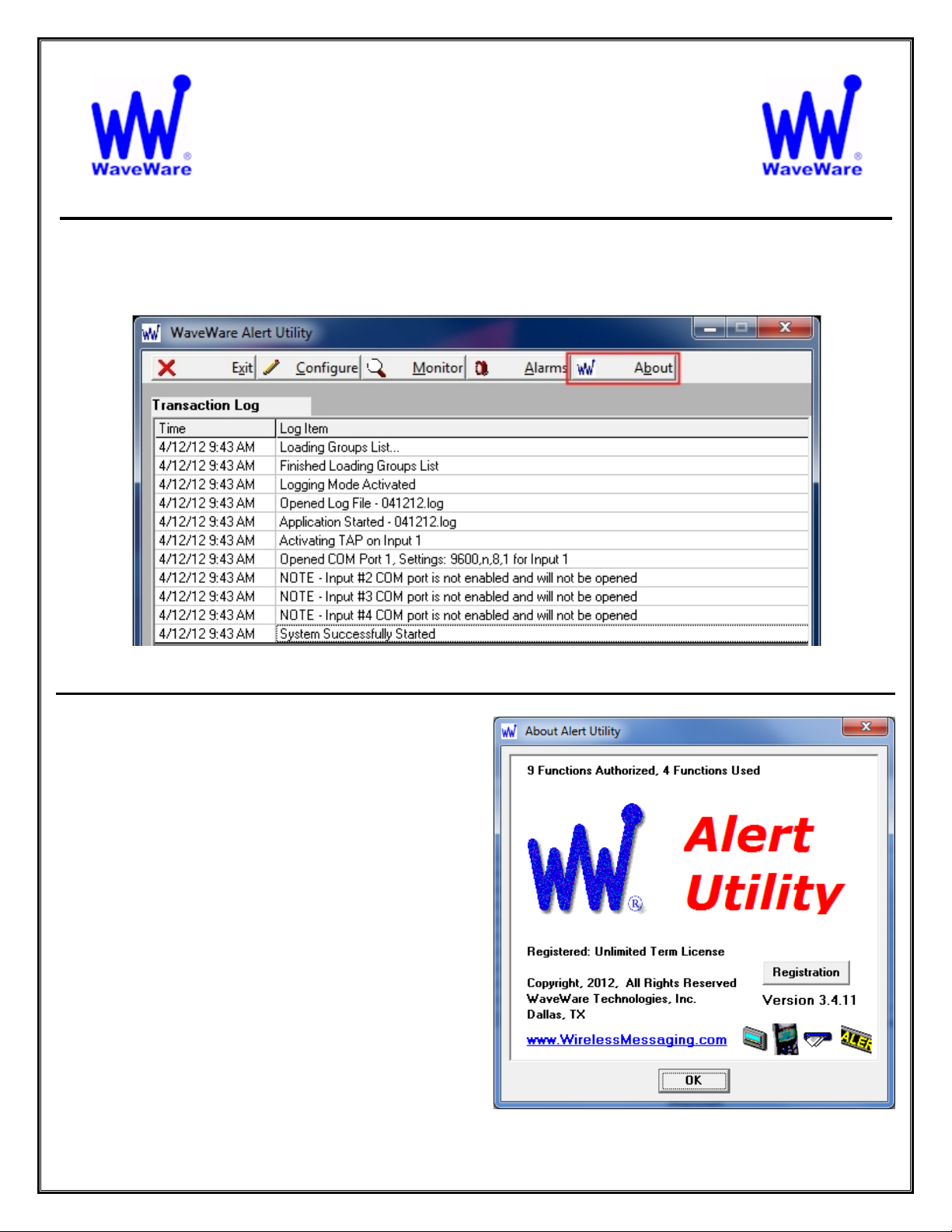
To Open the About Window, Click on the Button labeled “About”. See fig. 81
“We Deliver Information at the Speed of Light”
Alert Utility Software
About Alert Utility Software
Fig. 81 Main Screen – Click the “About” Button
For Reference, See Fig. 82
From this Screen, you can:
Check to See how many “Functions” are Authorized
Check to See how many “Functions” are being Used
Check the Version of the Software
Check to See if your Copy is Registered
Register your Copy of the Software
Registration Requires Purchase of the Software.
A 15 Day Trial Key is also Available on Request.
Fig. 82 About Window
48
Page 49

Alert Utility Software
WaveWare Alert Utility Software Allows you to Monitoring Serial Port Data for Alert Events, Output
Paging Messages, Output E-Mail, Output Caller ID Messages, and Control LED Message Boards.
Users, Please Contact your Software Dealer for Support
Dealers, Please Contact:
WaveWare Technical Support: Support@WirelessMessaging.com or 1.800.373.1466 x216
Software Developed by WaveWare Technologies, Inc.
Copyright © 2012
49
Page 50
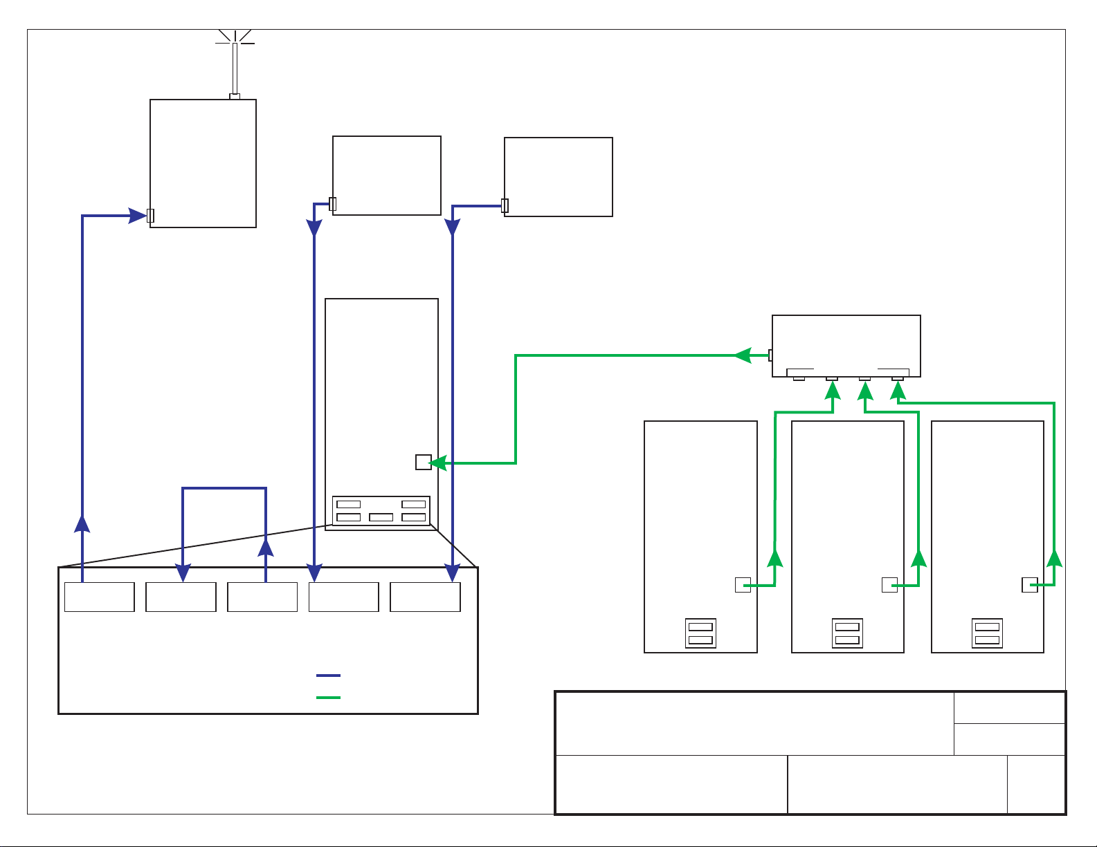
WaveWare
Out to SPS-5
SPS-5
Paging System
Serial Com Port
Loop Back
From EM into AU
Nurse Call
System
1
Serial Com Port
Output From NC Output From NC
“Desktop”
Server
Computer
EM Server and
AU Software
Ethernet
Port
Serial Com Ports
Nurse Call
System
2
Serial Com Port
Network Output to EM Desktop Server
“Desktop”
Computer
EM Client
Software
Network Hub
Network Inputs
“Desktop”
Computer
EM Client
Software
“Desktop”
Computer
EM Client
Software
AU
Output
AU EM AU AU
Input
Qty. Of 6 RS-232 Serial DB-9 Com Ports are Required.
Output NC Input NC Input
LEGEND:
AU = Alert Utility
EM = Enterprise Messaging
NC = Nurse Call
Larger View of Serial Com Ports
= RS-232 Serial Cable
= Ethernet Cable
IMPORTANT NOTES:
WaveWare ONLY Supports “ ” Pc’s using Windows XP with SP2 or Sp3 and Windows 7 OS’s.
WaveWare does Support any Servers or Server Os’s, No Virtual Machines or Terminals.
WaveWare does Support Multiple User Log-ins.
NOT
NOT
Desktop
Ethernet
Port
SPS-5 with Alert Utility and Enterprise Messaging
WAVEWARE TECHNOLOGIES
GARLAND, TEXAS USA
972-479-1702
Ethernet
Port
DWG. NUMBER
Ethernet
Port
DATE
8.7.12
DWN BY
Bob Clyburn
REV.
2
Page 51

Out to SPS-5 v8
WaveWare
SPS-5
Paging System
Serial Com Port
Nurse Call
System
1
Serial Com Port
Output From NC Output From NC Output to SL
Nurse Call
System
2
Serial Com Port
“Desktop”
Server
Computer
EM Server and
AU Software
Network Output to EM Desktop Server
Spectralink
Phone System
Serial Com Port
Network Hub
Network Inputs
Ethernet
Port
AU
Output
Loop Back
From EM into AU
AU EM AU AU
Input
Qty. Of 6 RS-232 Serial DB-9 Com Ports are Required.
Output NC Input NC Input Output
Serial Com Ports
SL
LEGEND:
AU = Alert Utility
EM = Enterprise Messaging
SL = Spectralink
NC = Nurse Call
Larger View of Serial Com Ports
= RS-232 Serial Cable
= Ethernet Cable
IMPORTANT NOTES:
WaveWare ONLY Supports “ ” Pc’s using Windows XP with SP2 or Sp3 and Windows 7 OS’s.
WaveWare does Support any Servers or Server Os’s, No Virtual Machines or Terminals.
WaveWare does Support Multiple User Log-ins.
NOT
NOT
Desktop
“Desktop”
Computer
EM Client
Software
Ethernet
Port
TITLE
SPS-5 with Alert Utility and Enterprise Messaging and
with Spectralink Phones.
WAVEWARE TECHNOLOGIES
GARLAND, TEXAS
972-479-1702
“Desktop”
Computer
EM Client
Software
Ethernet
Port
DWG. NUMBER
“Desktop”
Computer
EM Client
Software
Ethernet
Port
DATE
8.6.12
DWN BY
Bob Clyburn
REV.
2
Page 52
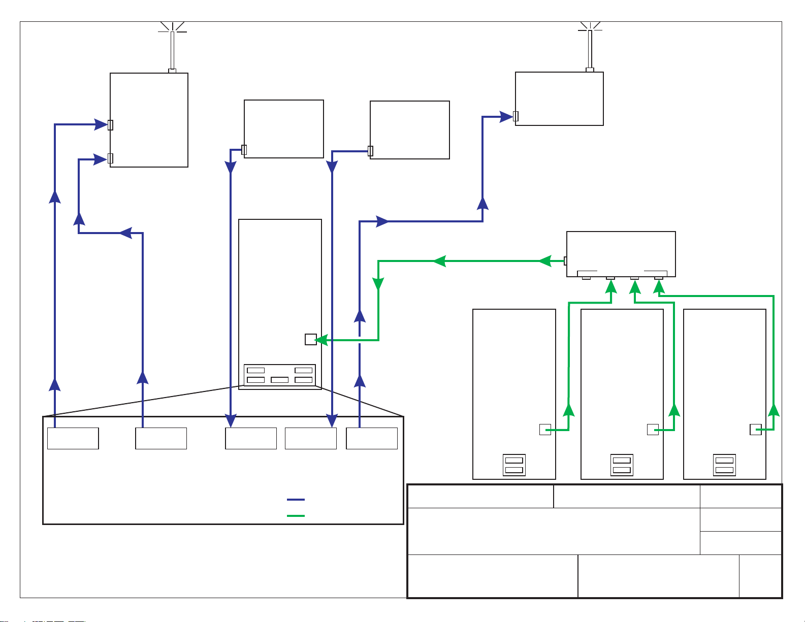
Out to SPS-5 v9
To Com Port 2
WaveWare
SPS-5 v9
Paging System
Serial Com Port 2
Serial Com Port 1
Nurse Call
System
1
Serial Com Port
Output From NC 1 Output From NC 2 Output to SPL
Nurse Call
System
2
Serial Com Port
“Desktop”
Server
Computer
EM Server and
AU Software
Network Output to EM Desktop Server
Spectralink
Phone System
Serial Com Port
Network Hub
Network Inputs
Ethernet
Port
SPL
AU
Out to SPS-5 v9
To Com Port 1
Serial Com Ports
EM AU AU
Output Output NC 1 Input NC 2 Input Output
To SpectraLinkTo Com Port 1To Com Port 2
LEGEND:
AU = Alert Utility
EM = Enterprise Messaging
SPL = Spectralink
NC = Nurse Call
Qty. Of 5 RS-232 Serial DB-9 Com Ports are Required.
= RS-232 Serial Cable
= Ethernet Cable
Larger View of Serial Com Ports
IMPORTANT NOTES:
WaveWare ONLY Supports “ ” Pc’s using Windows XP with SP2 or Sp3 and Windows 7 OS’s.
WaveWare does Support any Servers or Server Os’s, No Virtual Machines or Terminals.
WaveWare does Support Multiple User Log-ins.
NOT
NOT
Desktop
MATERIAL
“Desktop”
Computer
EM Client
Software
Or
Browser
Web Client
Ethernet
Port
FINISH
“Desktop”
Computer
EM Client
Software
Or
Browser
Web Client
Ethernet
NONE
Diagram of Setup for:
SPS-5 v9 with Alert Utility and Enterprise Messaging and
with Spectralink Phones.
WAVEWARE TECHNOLOGIES
DALLAS, TEXAS
972-479-1702
DWG. NUMBER
Port
“Desktop”
Computer
EM Client
Software
Or
Browser
Web Client
Ethernet
Port
DATE
05.10.2011
DWN BY
Bob Clyburn
APP.
REV.
1
 Loading...