


Xnucleo User Manual
share awesome hardware
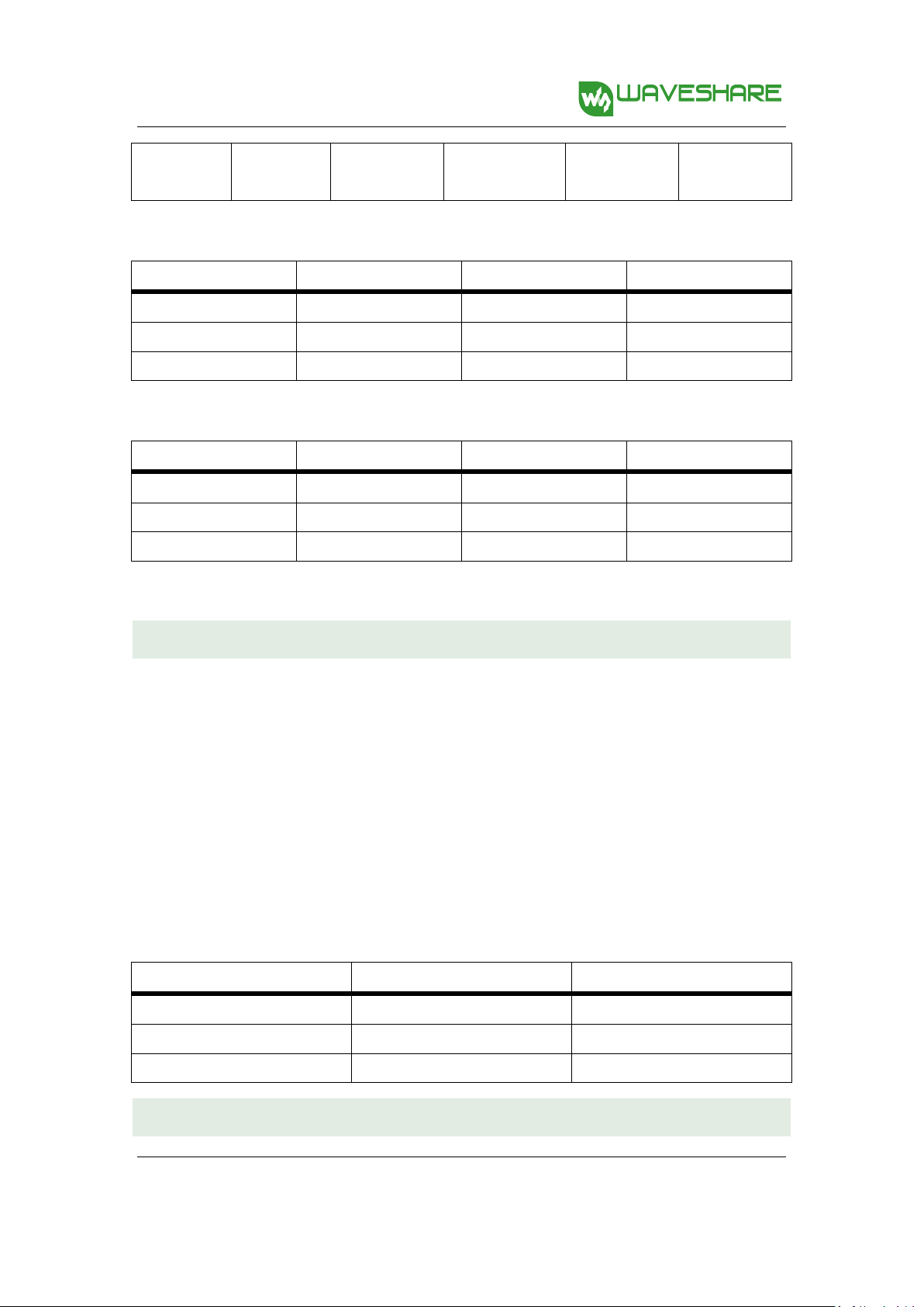
Compare
XNUCLEO
NUCLEO
Remarks
Arduino compatibility
UNO,
Leonardo
UNO
XNUCLEO can be configured by jumper to
compatible with UNO (default) or Leonardo
Arduino ICSP interface
Yes
None
ICSP is required by certain kinds of shields
USB connectivity
Yes
None
The USB connector of NUCLEO is for debugging
ONLY, not available for USB connection
USB connector
Micro USB
Mini USB
Micro USB is the advanced USB standard
Morpho headers mark
Most
None
Now you can check the PCB mark instead of
datasheet
Common interfaces are
connected via
Jumpers
0Ω resistors
Jumpers are much easier to use, need no soldering
UART debugging
Available
while
in-circuit
debugging
Not available
while in-circuit
debugging
The NUCLEO integrated ST-LINK/V2 functional chip
can be simulated as serial port, however, it's not
available while in-circuit debugging, whereas
XNUCLEO features a stand-alone USB TO UART
chip.
8MHz crystal
Yes
None
Timer is more accurate when using external 8MHz
crystal
32.768KHz crystal
Yes
None
Required for RTC
XNUCLEO USER MANUAL
FEATURES
Compatible with NUCLEO serials.
Arduino connectivity support, easy to connect with various Arduino shields and access the
massive Arduino resources
ST Morpho headers provide full access to all STM32 I/Os, easy for peripheral expansion
Supports mbed, build prototype quickly by mbed SDK and online tools
Comprehensive free software HAL library including a variety of software examples
Comes with a separated ST-LINK/V2 module
ADVANTAGES
V2.6.2, October. 25th 2016
1

Xnucleo User Manual
share awesome hardware
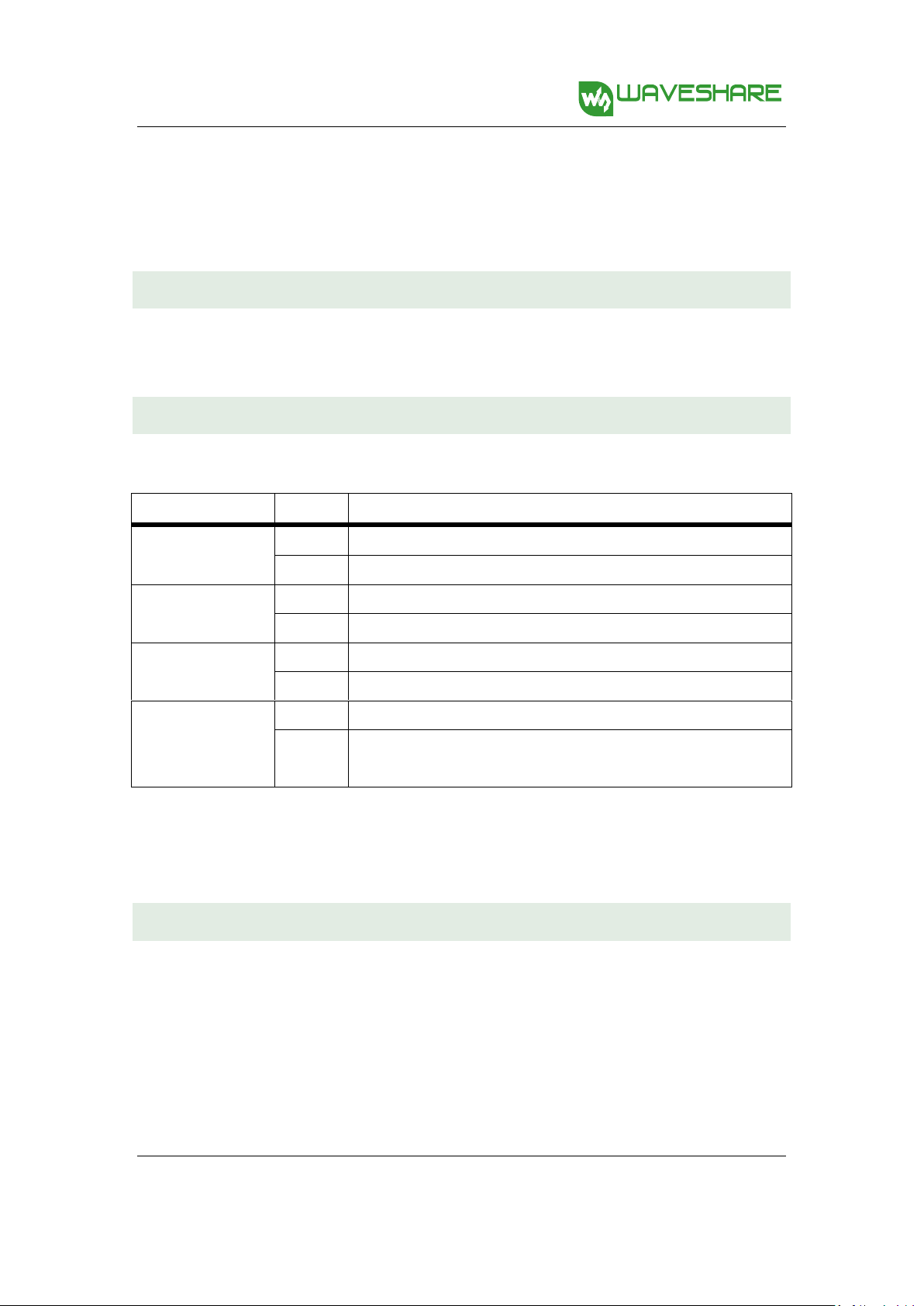
USB fuse
Yes (500mA)
None
The computer USB interface might be harmed
without fuse
LEDs 4 1
The more LEDs, the easier to monitor program
running status
UART indicator
Yes
None
Data communication is visible now
DC input
Yes
None
A convenience
Button position
Close to PCB
edge
Close to
Arduino
connector
The button won't be untouchable when
connecting with an Arduino shield if it were close
to the PCB edge
ST-LINK
Separated
Integrated
ST-LINK can be used anywhere else
Comes with USB cable
Yes
None
Ordering Information
Targeted MCU
XNUCLEO-F030R8
STM32F030R8T6
XNUCLEO-F103RB
STM32F103RBT6
XNUCLEO-F302R8
STM32F302R8T6
XNUCLEO-F401RE
STM32F401RET6
XNUCLEO-F411RE
STM32F411RET6
ORDERING INFORMATION
Table 1: Xnucleo series product information
The meaning of XNUCLEO-FXXXRY codification is as follows:
FXXX describes the STM32 MCU product line;
R describes the pin count (R for 64 pins);
Y describes the FLASH size (8 for 64K, B for 128K, C for 256K).
2
V2.6.2, October. 25th 2016

Xnucleo User Manual
share awesome hardware
CONTENTS
Features .................................................................................................................................................... 1
Advantages ............................................................................................................................................... 1
Ordering Information ............................................................................................................................... 2
1. Quick Start ........................................................................................................................................ 5
1.1. Development tool installation ......................................................................................... 5
1.1.1. CP2102 Virtual COM Port driver installation ........................................................... 5
1.1.2. STM32 ST-LINK Utility installation ........................................................................... 5
1.1.3. J-Link driver installation .......................................................................................... 5
1.2. Getting started ................................................................................................................ 5
1.2.1. Hardware configurations ........................................................................................ 6
1.2.2. Observing the actions ............................................................................................. 6
2. Hardware configuration ................................................................................................................... 7
2.1 Power supply settings ...................................................................................................... 7
2.1.1 Power supply input from the USB connector .......................................................... 7
2.1.2 Using CN2, VIN or E5V as external power supply .................................................... 8
2.1.3 External power supply output ................................................................................. 9
2.2 LED indicators .................................................................................................................. 9
2.2.1 FLASH LED ............................................................................................................... 9
2.2.2 PWR LED Power supply indicator ............................................................................ 9
2.2.3 Serial port working status LED indicators.............................................................. 10
2.3 Push button ................................................................................................................... 10
2.3.1 USER button .......................................................................................................... 10
2.3.2 RESET button ......................................................................................................... 10
2.4 JP2 (IDD) jumper settings .............................................................................................. 10
V2.6.2, October. 25th 2016
2.4.1 JP2 ON ................................................................................................................... 10
3

Xnucleo User Manual
share awesome hardware
2.4.2 JP2 OFF .................................................................................................................. 10
2.5 USART communication .................................................................................................. 10
2.5.1 Connecting the targeted MCU to serial port ......................................................... 10
2.5.2 Communication between the targeted MCU and shield or extension board ....... 11
2.6 ADC or I2C communication ........................................................................................... 12
2.7 SPI connector ................................................................................................................. 12
2.8 USB connector ............................................................................................................... 13
2.9 Solder bridges ................................................................................................................ 13
2.10 Extension connector ...................................................................................................... 13
3. How to use mbed on STM32 Xnucleo platform ............................................................................. 16
3.1 How to compile and download program under mbed .................................................. 16
3.1.1 Program compiling ................................................................................................ 16
3.1.2 Program downloading ........................................................................................... 16
3.2 How to export the Keil program from mbed ................................................................. 17
4. Periphery module Demo ................................................................................................................ 18
4.1 Connection between the Xnucleo board and Peripherals ............................................. 18
4.2 Demo explanations ........................................................................................................ 20
4.2.1 Data display mode................................................................................................. 20
4.2.2 The meanings of the returned data ...................................................................... 21
V2.6.2, October. 25th 2016
4

Xnucleo User Manual
share awesome hardware
1. QUICK START
1.1. DEVELOPMENT TOOL INSTALLATION
1.1.1. CP2102 VIRTUAL COM P ORT DRIVER INSTALLAT ION
STM32 Xnucleo includes an onboard USB TO UART interface based on CP2102 (“serial port”
hereafter) for code debugging. Before using this interface, you should install a CP2102 driver
firstly.
Run the installer: .\Xnucleo \tools\CP2102 driver\PreInstaller.exe
When the installation finished, connect the XNucleo board to a PC via the USB TO UART interface.
And you will find the CP210x USB to UART Bridge Controller in the Device Manager, if the driver
is installed successfully.
1.1.2. STM32 ST-LINK UTILITY INSTALLATION
Run the installer: .\Xnucleo user\tools\STM32 ST-LINK Utility\STM32 ST-LINK Utility_v3.4.0.exe
(For more detailed information about installation and usage of STM32 ST-LINK Utility, please
refer to the document provided by ST: .\Xnucleo user\tools\STM32 ST-LINK
Utility\Readme\STLINK Utility.PDF. You can also download the latest installer from the ST
website).
When the installation finished, connect the ST-LINK/V2(mini) module to a PC. You will find the
STMicroelectronics STLink dongle in the Device Manager, if the driver is installed successfully.
1.1.3. J-LIN K DRI VER INSTALLATION
Run the installer:
.\Xnucleo user\tools\JLinkARM\Setup_JLinkARM_V415e.exe
When the installation finished, connect the J-Link emulator to a PC. You will find the J-Link driver
in the Device Manager, if the driver is installed successfully.
1.2. GETTING STARTED
Please follow the sequence below to configure the STM32 Xnucleo board and launch the demo
software:
V2.6.2, October. 25th 2016
5

Xnucleo User Manual
share awesome hardware
1.2.1. HARDWARE C ONFIG URATI ONS
1) Jumper settings
Set JP3 to U5V;
Set JP2 to ON;
2) Power supply and power selection
For using a USB power supply, connect the Xnucleo board to a PC with a USB cable through
the onboard USB connector;
For using an external power supply, connect the power supply socket CN2 on the Xnucleo
board to a 6~12V power adapter.
3) Connect the ST-LINK/V2 (mini) debugger/programmer to the SWD connector
Notices: It is recommended to plug in the USB power supply or the external power supply
before connecting the ST-LINK/V2(mini) module to the SWD interface. Otherwise, the
ST-LINK/V2(mini) initialization may be failure.
1.2.2. OBSERVING THE A CTION S
The blinking of the USER LED indicator will change from fast to slow or from slow to fast, when
clicking the USER key.
V2.6.2, October. 25th 2016
6

Xnucleo User Manual
share awesome hardware
Jumper
Description
2. HARDWAR E CON FIGURATION
2.1 POWER SUPPLY SETTINGS
The power supply of the STM32 Xnucleo board is provided either by the host PC through the USB
cable, or by an external source:
VIN (7V~12V) or +3V3 power pins on CN6;
E5V(5V) pin on CN7;
CN2 power supply connector (7V~12V).
In case VIN, E5V, +3V3 or CN2 is used to power the Xnucleo board, you should use an external
power supply unit.
2.1.1 POWER SUPPLY INPUT FROM THE USB CONNECTOR
All parts of the STM32 Xnucleo board and Shield can be powered from the ST-LINK/V2 (mini) USB
connector by the host PC.
In case the ST-LINK/V2 (mini) USB connector is used to power the Xnucleo board, the host PC will
provide 150mA current at maximum as 3.3V voltage is outputted from the ST-LINK/V2 (mini)
USB connector to the Xnucleo board. And 300mA current at maximum may be provided when
5V voltage is outputted to the Xnucleo board. In case of the board requiring the current more
than 300mA, it should be mandatory to use an external power supply as explained in the next
chapter.
Each part of STM32 Xnucleo including the extension board can be powered by USB(U5V).
However, if the maximum current consumption of the board exceeds 300mA, the USB may be
damaged. When the board is power supplied by USB(U5V), a jumper must be connected
between pin 1 and pin 2 of JP5 as shown in Table 2.
Table 2: Power-related jumper
V2.6.2, October. 25th 2016
7

Xnucleo User Manual
share awesome hardware
JP5
U5V (ST-LINK VBUS) is used as power source when JP5 is set as shown below (Default
setting)
CN2, VIN or E5V is used as power source when JP5 is set as shown below
Name
Pins
Voltage range
Max. current
Limitations
CN2
CN2
6V~12V
800mA
The inputted current is in connection
with the inputted voltage:
For CN2/VIN = 7V,
the inputted current is 800mA.
For 6V < CN2/VIN <= 9V,
the inputted current is 450mA.
For 9V<CN2/VIN(< or =)12V,
the inputted current is 250mA
VIN
CN6 pin 8
or
CN7 pin 24
E5V
CN7 pin 6
4.75V~5.25V
500mA
------
2.1.2 USING CN2, VIN OR E5V AS EX TERNAL POWER SUPPLY
CN2, VIN or E5V can be used as external power supply in case the current consumption of
Xnucleo and its extension boards exceeds the allowed current on USB. In this condition, it is
mandatory to power supply the board using the external power source firstly, then connect the
USB cable and ST-LINK/V2 (mini) to the PC to ensure that the Xnucleo board can work properly.
Table 3: External power source parameters
Notices: The following power sequence procedure must be respected when using an external
power source:
1) Set JP3 to U5V;
2) Connect the external power source to CN2, VIN or E5V;
3) Power on the external power supply CN2, VIN: 7V~12V, or E5V: 5V;
4) Check that PWR LED is turned ON;
5) Connect the PC to USB connector or ST-LINK/V2(mini) on Xnucleo.
V2.6.2, October. 25th 2016
8

Xnucleo User Manual
share awesome hardware
FLASH LED
MCU PIN
LED1
D13(PA5/PB13)
LED2
PC9
LED3
PC8
LED4
PC5
If this order is not respected, the board may be supplied by VBUS or ST-LINK/V2(mini) firstly, and
the following risks may be encountered:
If more than 300 mA current is needed by the board, the PC may be damaged or the current
supply can be limited by the PC. As a consequence the board cannot work correctly.
2.1.3 EXTERNAL POWER SUPP L Y OUT PUT
When powered by CN2, VIN or E5V, the +5V (CN6 pin 5 or CN7 pin 18) can be used as
output power supply for an Arduino shield or an extension board. In this case, the
maximum current of the power source specified in Table 3 needs to be respected.
The +3.3 V (CN6 pin 4 or CN7 pin 12 & 16) can be used also as power supply output. The
current is limited by the maximum current capability of the regulator U4 (500 mA max).
2.2 LED INDICATORS
The LEDs on the STM32 Xnucleo board is used to provide information about the Xnucleo working
status.
2.2.1 FLASH LED
Table 4: The relationship between LED and the pins of MCU
It is easy to use each LED by setting JP7. For XNUCLEO-F302R8, the pin PB13 is connected to the
MCU pin D13. And for other XNUCLEO devices, the pin PA5 is connected to the MCU pin D13.
When the I/O is HIGH value, the FLASH LED is on. And when the I/O is LOW, the FLASH LED is off.
2.2.2 PWR LED POWER SUPPLY INDICATOR
V2.6.2, October. 25th 2016
9

Xnucleo User Manual
share awesome hardware
The PWR LED default color is red. It indicates the power supply status of the STM32 Xnucleo
board. The red LED indicates that the MCU part is powered by +5V.
2.2.3 SE RIAL PORT WORKING STATUS LED I NDICATORS
TX indicator is in green, and RX indicator in blue. The blinking TX indicator means the MCU of
STM32 Xnucleo board is sending message to the targeted PC. The blinking RX indicator means
the MCU of STM32 Xnucleo board is receiving message from the targeted PC.
2.3 PUSH BUTTON
2.3.1 USER BUTTON
The USER button is connected to the I/O PC13(pin 2) of the targeted MCU by setting JP6 to ON;
2.3.2 RESET B UTTON
This RESET button is connected to NRST, and is used to reset the targeted MCU.
2.4 JP2 (IDD) JUMPER SETTINGS
2.4.1 JP2 ON
STM32 microcontroller is powered (default).
2.4.2 JP2 OFF
When this jumper is removed, STM32 microcontroller is not powered. But you can connect an
ammeter on the JP6 to measure the STM32 microcontroller current.
2.5 USART COMMUNICATION
The USART2 interface available on PA2 and PA3 of the STM32 microcontroller can be connected
to Virtual COM Port, STMicroelectronics Morpho connector or to Arduino connector.
2.5.1 CONNECTING T HE TARGETED MCU TO SERIAL PORT
Please set the JP4 as follows, to connect the targeted MCU to serial port (For more information,
please refer to Table 6 and Table 7).
V2.6.2, October. 25th 2016
10

Xnucleo User Manual
share awesome hardware
Model\pin
PC6,PC7
PC10,PC11
PA9,PA10
SB70,SB71
SB72,SB73
XNUCLEO
-F030R8
None
None
USART1
None
XNUCLEO
-F103RB
None
USART3
USART1
(NC)
ON
OFF
XNUCLEO
-F302R8
None
USART3
USART1
(NC)
ON
OFF
Connect the RX/PA3 of JP4 to the TXD;
Connect the TX/PA2 of JP4 to the RXD.
2.5.2 COMMUNICATION BETWEEN THE TARGET ED MCU AND SHIE LD OR
EXTENSION BOARD
If the communication between the targeted MCU and shield or extension board is required, you
should set the JP4 and the RX/D0 and TX/D1 on CN9 as follow (For more information, please
refer to Table 6).
Connect the RX/PA3 of JP4 to the RX/D0;
Connect the TX/PA3 of JP4 to the TX/D1.
In such case it possible to connect another USART (if another USART is available on the targeted
MCU) to the targeted MCU through Virtual COM Port using flying wires as follow
Connect the TX/PC10/PC6 of JP4 to RXD;
Connect the RX/PC11/PC of JP4 to TXD.
Here is the jumper setting for connecting to XNUCLEO-F030R8:
Connect the TX/PA9 of JP4 to RXD;
Connect the RX/PA10 of JP4 to TXD.
Notices: You should select a proper USART by referring to Table 5 and make corresponding
hardware configurations, according to your actual demand. The USARTs (USART1 and USART3)
listed in this table are unavailable under mbed, since only USART2(PA2, PA3) is defined for mbed.
Therefore, when the USART-related APIs (such as printf) are required under mbed, you should
select USART2(PA2, PA3) to connect to Virtual COM Port or CN9 on the pins RX/D0 and TX/D1.
Table 5: USART-related pins and jumpers
V2.6.2, October. 25th 2016
11
Xnucleo User Manual
share awesome hardware
XNUCLEO
-F401RE
USART6
None
USART1
(NC)
OFF
ON
A B C
D
ARDUINO PORT
MCU PIN
CP2102 PIN
MCU PIN
RX/D0
RX/PA3
TXD
RX/PC11/PC7
TX/D1
TX/PA2
RXD
TX/PC10/PC6
A B C
D
ARDUINO PORT
MCU PIN
CP2102 PIN
MCU PIN
RX/D0
RX/PA3
TXD
RX/PA10
TX/D1
TX/PA2
RXD
TX/PA9
A B C
MCU PIN
ARDUINO PORT
MCU PIN
SCL/PB8
A5
PC0/ADC
SDA/PB9
A4
PC1/ADC
Table 6: Connections of JP4 pins
Table 7: Connections of NUCLEO-F030R8 JP4
2.6 ADC OR I2C COMMUNICATION
If ADC or I2C communication is required, you can connect the ADC interface or the I2C interface
to the Arduino connector or the ST Morpho connector by setting the JP5.
Here are the relative settings to JP5:
The pins A4 and A5 of JP5 should be connected to the Arduino connector on the pins A4 and A5 (the
pin 5 and the pin 6 of CN8) or the ST Morpho connector on the pins 36 and 38 of CN7 respectively;
The pins SDA/PB9 and SCL/PB8 of JP5 corresponding to the I2C interface of STM32 MCU;
The pins PC1/ADC and PC0/ADC of JP5 corresponding to the ADC interface of STM32 MCU.
Table 8: Connections of JP5 pins
2.7 SPI CONNECTOR
V2.6.2, October. 25th 2016
12
Xnucleo User Manual
share awesome hardware
Bridge
State
Description
SB74
ON
IOREF is connected to 3.3V
OFF
IOREF unconnected
SB75
ON
IOREF is connected to 5V
OFF
IOREF unconnected
SB45 (VBAT/VLCD)
ON
VBAT or VLCD on STM32 MCU is connected to VDD.
OFF
VBAT or VLCD on STM32 MCU is not connected to VDD.
SB57 (VREF+)
ON
VREF+ on STM32 MCU is connected to VDD.
OFF
VREF+ on STM32 MCU is not connected to VDD and can be provided from
pin 7 of CN10
The pins D11, D12 and D13 of Arduino connector are SPI interfaces. For XNUCLEO-F302R8, the
pins PB13, PB14 and PB15 are connected to the pins D13, D12 and D11, respectively. And for
other XNUCLEO devices, the pins PA5, PA6 and PA7 are connected to the pins D13, D12, and D11,
respectively.
2.8 USB CONNECTOR
Except the XNUCLEO-F030R8, all the other XNUCLEO devices have reserved a USB connector
which can be enabled by setting JP1 to ON.
2.9 SOLDER BRIDGES
Table 9: solder bridges
Notes: All the other solder bridges present on the STM32 Xnucleo board are used to configure
several IOs and power supply pins for compatibility of features and leads with STM32 MCU
supported.
2.10 EXTENSION CONNECTOR
The following figures show the signals connected by default to Arduino connectors (CN5, CN6,
CN8, CN9) and to ST Morpho connector (CN7 and CN10), for each STM32 Xnucleo board.
V2.6.2, October. 25th 2016
13

Xnucleo User Manual
share awesome hardware
Figure 1: XNUCLEO-F030R8
Figure 2: XNUCLEO-F103RB
V2.6.2, October. 25th 2016
Figure 3: XNUCLEO-F302RC
14

Xnucleo User Manual
share awesome hardware
Figure 4: XNUCLEO-F401RE
Figure 5: XNUCLEO-F411RE
V2.6.2, October. 25th 2016
15

Xnucleo User Manual
share awesome hardware
Xnucleo
Nucleo
XNUCLEO-F030R8
NUCLEO-F030R8
XNUCLEO-F103RB
NUCLEO-F103RB
XNUCLEO-F302R8
NUCLEO-F302R8
XNUCLEO-F401RE
NUCLEO-F401RE
XNUCLEO-F411RE
NUCLEO-F411RE
3. HOW TO USE MBED ON STM32 XNUCLEO PLATFORM
Xnucleo series is fully compatible with Nucleo series and can run the Nucleo Demos directly.
Therefore, you can develop your STM32 Xnucleo applications based on the applications of
STM32 Nucleo. Table 10 gives the relationship between Xnucleo series and Nucleo series.
Table 10: Relationships between Xnucleo series and Nucleo series
The operations presented in this document are based on XNUCLEO-F103RB. For different
Xnucleo devices, there may be some differences in configuring the development environment.
So users should operate according to the actual conditions.
3.1 HOW TO COMPILE AND DOWNLOAD PROGRAM UNDER MBED
In this section, we only present the ways to compile and download program, since it does not
have room to address every factor of mbed. For more detailed information about the usage of
mbed, please refer to the documents provided by mbed organization.
3.1.1 PROGRAM COMPILING
Here we take XNUCLEO-F103RB as an example. Start the mbed software, and open a program,
such as Nucleo_printf. Then, click the button Compile for program compiling. If the program has
no error, Compile Output will show “Success!” after the compiling is finished. And the file
Nucleo_printf_NUCLEO_F103RB.bin will be generated. This file can be found in the specified
save path (This save path is modifiable).
3.1.2 PROGRAM DOWNLOADING
1) Run the STM32 ST-LINK Utility, and select file->Open file. Then, open the file
V2.6.2, October. 25th 2016
Nucleo_printf_NUCLEO_F103RB.bin.
16

Xnucleo User Manual
share awesome hardware
Baud rate
115200
Data bit
8
Stop bit
1
Parity
None
2) Connect the USB TO UART interface on the board to your PC with a USB cable, and then
connect ST-LINK/V2(mini) module to download the .bin file. Then, set the JP5 to U5V. For
the JP4 setting, please refer to Section 2.5 USART communication. The serial port should be
configured according to Table 11.
Table 11: Serial port configuration
3) When the program downloading finished, COM port will receive the following information:
Hello World!
This program runs since 1 second.
This program runs since 2 seconds.
This program runs since 3 seconds.
This program runs since 4 seconds.
This program runs since 5 seconds.
...
At this time, the USER LED is blinking in the frequency of 0.5Hz. And the TX LED keeps
blinking to indicate that STM32 Xnucleo is sending message to the PC.
3.2 HOW TO EXPORT THE KEIL PROGRAM FROM MBED
Circuit debugging are unavailable in mbed. However, mbed has “Import Program” and “Export
Program” functions. You can export the programs in mbed as Keil programs to perform
debugging.
The mbed library file can also be exported, which includes the HAL library of STM32 MCU. Under
the Keli environment, mbed libraries can be applied or modified directly, and can be
transplanted into other applications.
17
V2.6.2, October. 25th 2016

Xnucleo User Manual
share awesome hardware
Sensor
Pin
XNUCLEO-F03
XNUCLEO-F10
XNUCLEO-F30
XNUCLEO-F40
XNUCLEO-F41
The relative operations are as follow:
In the mbed, open the program you want to export. Then, right click the program name in the
Program Workspace, and select Nucleo_printf->Export Program, as Figure 6 shows.
Figure 6: Exporting as Keil program
In the Export Toolchain pull-down menu of the pop-up window, select Keil μVision. Then, the
programs in mbed can be exported as Keil programs and performed Keil debugging. For more
detailed information, please refer to the Keil-related technical documents.
4. PERIPHERY MODULE DEMO
Besides Nucleo Demos, the Demos for different periphery modules provided by Waveshare are
supported by Xnucleo series as well. The corresponding devices to the periphery module Demos
include but not limited to: Temperature-Humidity Sensor, Rotation Sensor, Color Sensor, UV
Sensor, Water Sensor, Moisture Sensor, Vibrating Sensor, Tilt Sensor, Laser Sensor, Gas Sensor,
Sound Sensor, Flame Sensor, Hall Sensor, Metal Sensor, Infrared Reflective Sensor, OLED display
module and so on. And these Demos for different periphery modules are integrated into a big
Demo (“periphery module Demo” hereafter) for convenience.
4.1 CONNECTION BETWEEN THE XNUCLEO BOARD AND PERIPHERALS
Table 12: Connection between the XNUCLEO and sensors
18
V2.6.2, October. 25th 2016

Xnucleo User Manual
share awesome hardware
0R8
3RB
2R8
1RE
1RE
Temperature-Hum
idity Sensor
DOU
T
PB3/D3
PB3/D3
PB3/D3
PB3/D3
PB3/D3
Rotation Sensor
SIA
PB4/D5
PB4/D5
PB4/D5
PB4/D5
PB4/D5
SIB
PB5/D4
PB5/D4
PB5/D4
PB5/D4
PB5/D4
SW
PB10/D6
PB10/D6
PB10/D6
PB10/D6
PB10/D6
Color Sensor
LED
3.3V
3.3V
3.3V
3.3V
3.3V
OUT
PC7/D9
PA1/A1
PA1/A1
PA1/A1
PA1/A1
S3
PA9/D8
PA9/D8
PA9/D8
PA9/D8
PA9/D8
S2
PA8/D7
PA8/D7
PA8/D7
PA8/D7
PA8/D7
S1
NC
NC
NC
NC
NC
S0
NC
NC
NC
NC
NC
UV Sensor
Water Sensor
Moisture Sensor
Tilt Sensor
Laser Sensor
Gas Sensor
Sound Sensor
Flame Sensor
Hall Sensor
Metal Sensor
Infrared Reflective
Sensor
AOU
T
PA4/A2
PA4/A2
PA4/A2
PA4/A2
PA4/A2
DOU
T
PA10/D2
PA10/D2
PA10/D2
PA10/D2
PA10/D2
19
V2.6.2, October. 25th 2016

Xnucleo User Manual
share awesome hardware
0.96inch OLED
DIN
PA7/D11
PA7/D11
PB15/D11
PA7/D11
PA7/D11
CLK
PA5/D13
PA5/D13
PB13/D13
PA5/D13
PA5/D13
CS
PB8/A5
PB8/A5
PB8/A5
PB8/A5
PB8/A5
D/C
PB9/A4
PB9/A4
PB9/A4
PB9/A4
PB9/A4
RES
PB0/A3
PB0/A3
PB0/A3
PB0/A3
PB0/A3
Notices:
The pins VCC and GND of the sensors listed above should be connected to the pins VCC and
GND of IO Expansion Shied. For more detailed information, please refer to IO Expansion
Shied User Manual.
Some of the sensors may only lead out the pin AOUT or the pin DOUT. In this case, the
additional reserved pin(s) of IO Expansion Shied can be left unconnected. One IO Expansion
Shied can only connect one sensor at a time.
4.2 DEMO EXPLANATIONS
When the Demo is running, the LED1 on the XNUCLEO board will blink at the rate of every 2
seconds.
4.2.1 DATA DISPLAY MODE
For the periphery module Demo, there are two modes for displaying the returned information
from the module: OLED and Screen Print (relative information is sent to the PC via the serial port
every 500 ms). Here is an example:
Figure 7: OLED displays relative sensor parameters
20
V2.6.2, October. 25th 2016

Xnucleo User Manual
share awesome hardware
Symbol
Meanings
Remarks
T
Temperature
Unit: Degrees Celsius
H
Humility
Air humility percentage (%)
D
AD value
Voltage value in the format of 12 BIT. It can be converted to actual value by
linear transformation.
A
DA value
Voltage value
S
State
There are two states: ON and OFF
Rot
Rotation count
for rotation
encoder
For clockwise rotation, the counter value is incremented by 1; for anticlockwise
rotation, the counter value is decremented by 1. The count can be a minimum of
0 and maximum 255.
SW
Button press
count for
rotation
encoder
It supports single click, double click, long press and continued shot
R
Red value
Users can get the actual color on the basis of the RGB value. For more
information, please refer to Color Sensor User Manual
G
Green value
Users can get the actual color on the basis of the RGB value. For more
information, please refer to Color Sensor User Manual
At the same time, relative data will be outputted:
/*----------------------*/
T: 23 C H: 34
D: 3868 A: 3.116 S: OFF
Rot: 227 SW: 52
R: 20 G: 6 B: 105
RTC: 12:1:4 KEY: 10
/*----------------------*/
4.2.2 THE MEA NINGS OF THE RETURNED DATA
Table 13: The meanings of relative symbols
V2.6.2, October. 25th 2016
21

Xnucleo User Manual
share awesome hardware
B
Blue value
Users can get the actual color on the basis of the RGB value. For more
information, please refer to Color Sensor User Manual
RTC
Real time clock
The outputted time information from RTC.
KEY
USER button
press count for
Xnucleo
Its usage is the same as the SW of the rotation encoder.
V2.6.2, October. 25th 2016
22
 Loading...