

e-Paper ESP8266 Driver Board User Manual
e-Paper ESP866 Driver Board
USER MANUAL
PRODUCT OVERVIEW
e-Paper ESP866 Driver Board is hardware and software tool intended for loading pictures
to an e-Paper from PC/smart phone internet browser via Wi-Fi net.
The hardware of the driver board is a small PCB with e-Paper driver and ESP8622 module.
The PCB has two series of pins, which allow you to apply all of Arduino projects for ESP8266
boards.
The software of the driver board is a one-page html-application providing picture
correction service (is useful in that case if original colors and size aren’t suitable for the
currently used display) and uploading it to the e-Paper.
PRODUCT FEATURES
No need to convert a picture to special image formats, it can be any image format
supported by your browser.
E-Papers have 2, 3, 4 hardware colors, but the driver board can mix them (by the Dithering)
to obtain more color combinations for better image shade rendering of the original picture.
The hardware of the driver board needs a connection to LAN, but it doesn't need the
internet connection.
APPLICATIONS
The tool is intended to be the start point in developing of the electrically changeable sign based
on e-Paper display. Possible applications are:
Price tags in a supermarket;
Small information screen in the customer service window (clerk’s name);
Advertising screen in lift near buttons of the control panel;

e-Paper ESP8266 Driver Board User Manual
CONTENT
Product Overview .......................................................................................................................................................... 1
Product Features .................................................................................................................................................. 1
Applications ........................................................................................................................................................... 1
SEVER_SIDE Application .............................................................................................................................................. 3
Instruction of The Arduino IDE ........................................................................................................................ 3
Source Code Compilation ................................................................................................................................. 4
E-PAPER TYPE SETTING .................................................................................................................................... 5
THE CLIENT-SIDE APPLICATION ............................................................................................................................. 5
User Interface ........................................................................................................................................................ 6
Image Processing ................................................................................................................................................. 7
LEVEL ............................................................................................................................................................... 7
DITHERING .................................................................................................................................................... 8
DATA TRANSMISSION PROTOCOL ............................................................................................................... 9
COMMANDS ............................................................................................................................................. 10
Initialization Algorithm........................................................................................................................... 10
DATA TRANSMISSION ALGORITHM ................................................................................................ 12
DATA PIXEL FORMAT ............................................................................................................................. 13
HARDWARE .................................................................................................................................................................. 16
PINOUT................................................................................................................................................................. 16
OUTLINE DIMENSION ..................................................................................................................................... 17
e-Paper ESP8266 Driver Board User Manual
SEVER_SIDE APPLICATION
The e-Paper Image Loader described in this document is a source code written in C
language. To compile the source code of the e-Paper Image Loader you need the Arduino IDE.
To run the driver board you need also a serial port monitoring software (you can use Arduino
IDE’s or other software with a serial port monitoring function), Wi-Fi router and PC / smart
phone connected to the router.
INSTRUCTION OF THE ARD UI N O I D E
If the Arduino IDE with ESP8266 board is already installed, then skip this step.
1. Go to the
https://www.arduino.cc/en/Main/Software
site and install the IDE for your OS.
Note: the installation of the new version doesn’t remove your projects or files.
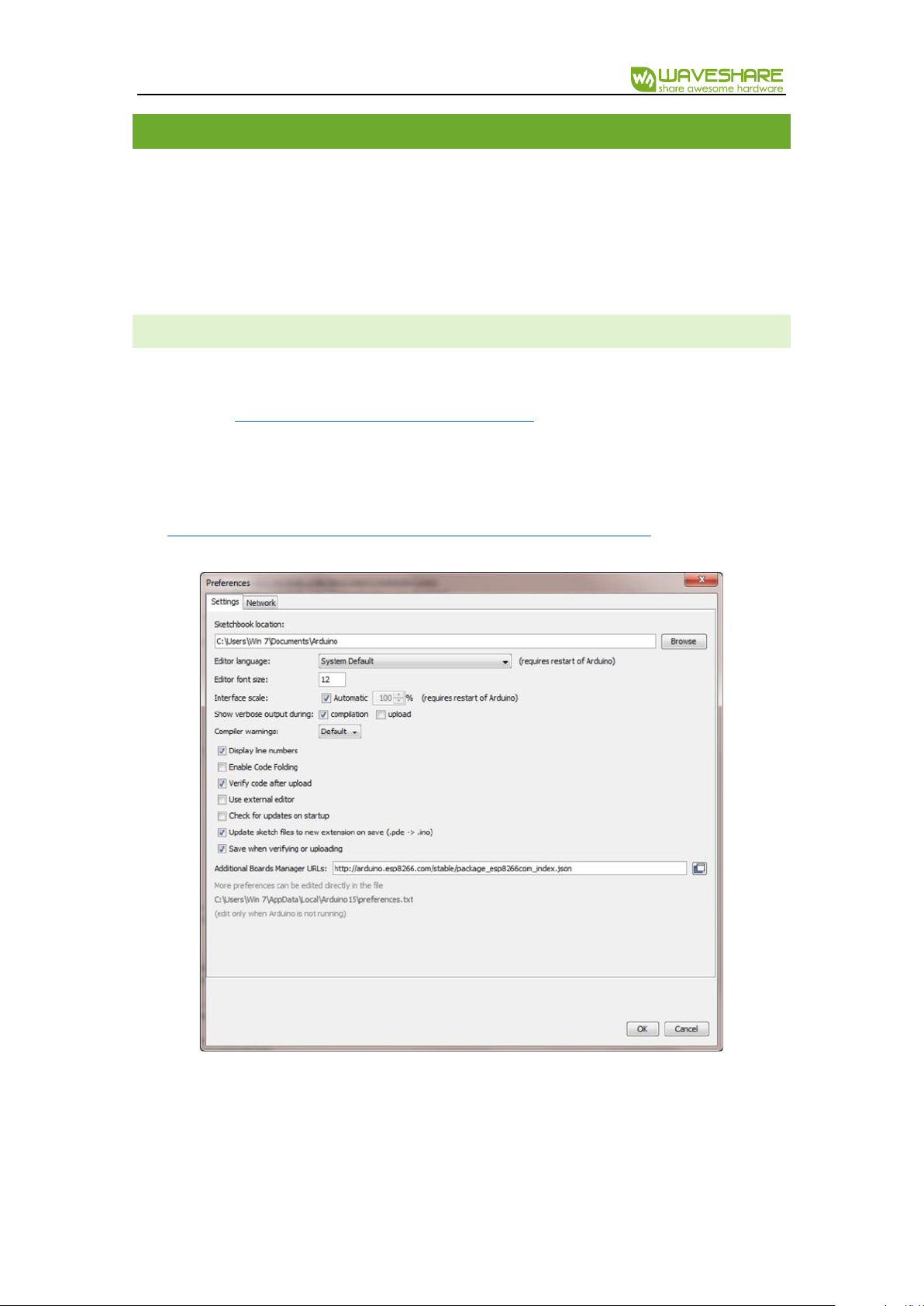
2. In Arduino IDE open
File->Preferences
menu item, open tab
Settings
, text
http://arduino.esp8266.com/stable/package_esp8266com_index.json
into to text box
Additional Boards Manager URLs
(figure 1) and click Ok.
3. In Arduino IDE open Tools->Board:(Your current boars selection)->Boards
Manager…, find and/or install ESP8266 by ESP8266 Community.
e-Paper ESP8266 Driver Board User Manual
SOURCE CODE COMPILATI ON
The source code consists of following files:
loader.ino
is the main file. It has two functions:
setup
and
loop
. If you need to add/initialize
some other software components, do it in
setup
function.
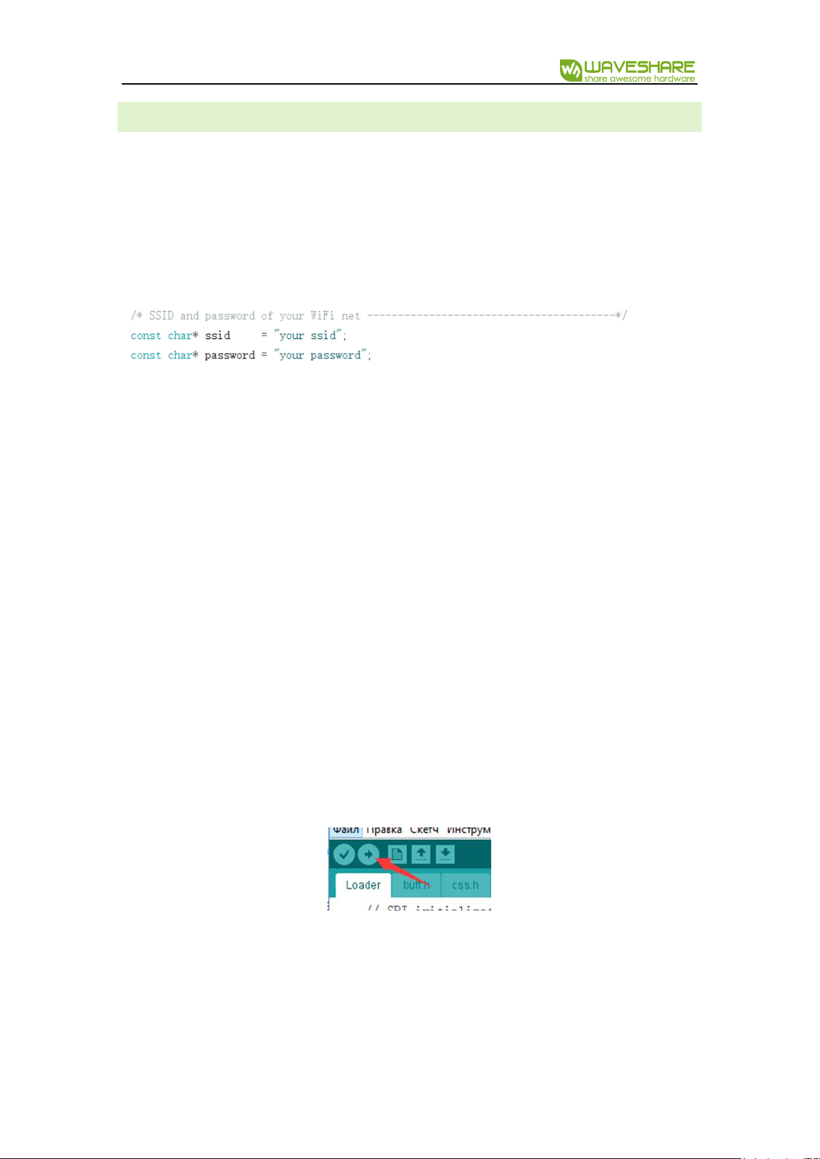
srvr.h
describes functions of ESP8266 Wi-Fi server. To compile and run the loader as it is
you just need to change constants
ssid
and
password
as in your Wi-Fi router.
html.h, css.h
and
scripts.h
contain functions sending the web page of the loader to a
client’s browser. Due to limited size of data sent to the client, the page is divided on a few
small files, hasn’t any comments, not useful spaces and some new line characters.
Comments to the page content see in
page
directory of the source code.
buff.h
contains one byte-buffer and 3 functions for accumulating data of client’s POST
requests. The buffer is used for easier data converting from 1- ,2-bit pixel format of received
image data to 1- ,2- ,4-bit pixel format of e-Paper’s image.
epd1in54.h, epd2in13.h, epd2.7.h, epd2in9.h, epd4in2.h, epd7in5.h
contain initialization
functions for correspondent displays including data about brightness and saturation of
colors (lut-massives).
epd.h
contains functions controlling e-Paper states (initialization, color-channel selection,
loading, refreshing and turning to the deep sleeping mode).
Note: the source code is written in C (without any classes) to easier porting to other compilers.
Connect one of supported e-Paper to the board, compile & flash the software to ESP8266
memory by clicking the button “Load” (figure 2).
Note: if you didn’t change the code, you are trying to compile it the first time and the
compilation is failed, check you chose right board in Tools->Board (figure 3).
e-Paper ESP8266 Driver Board User Manual
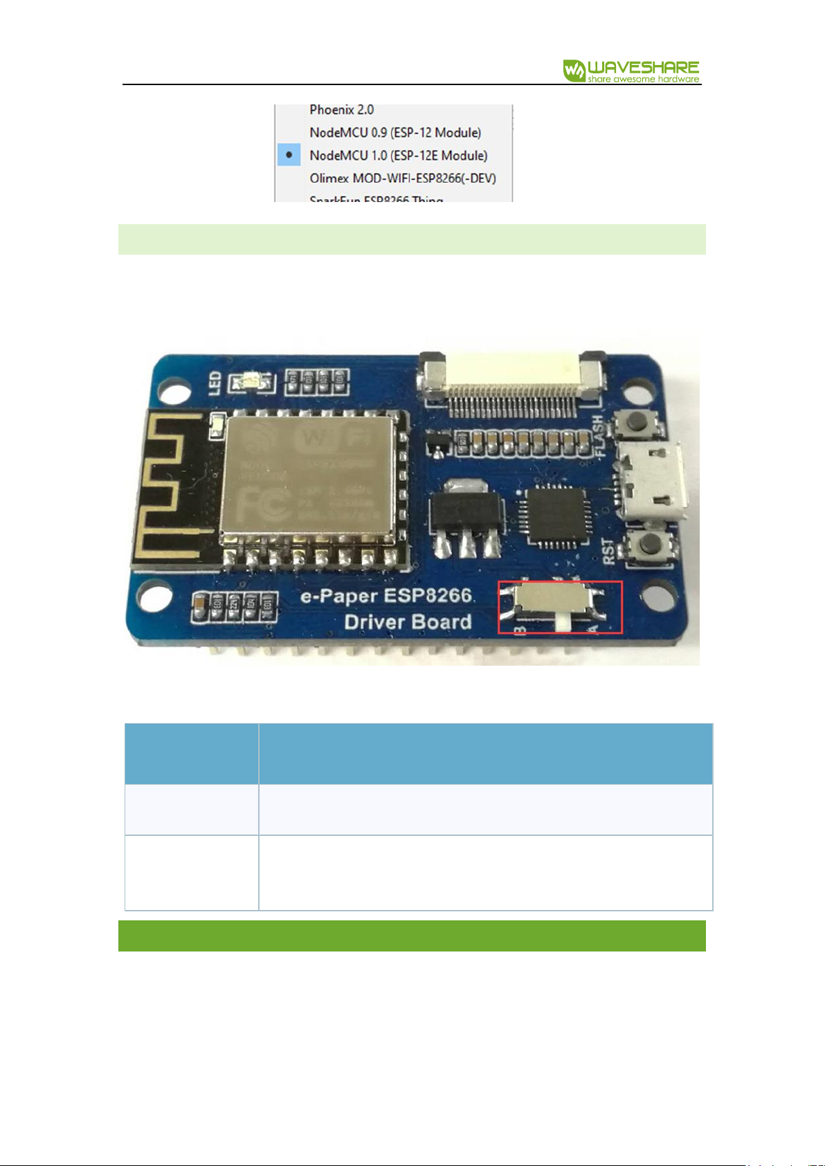
E-PAPER TYPE SETTING
Before you send some picture to your e-Paper, check please the trigger on the board is in
proper state (Figure 4).
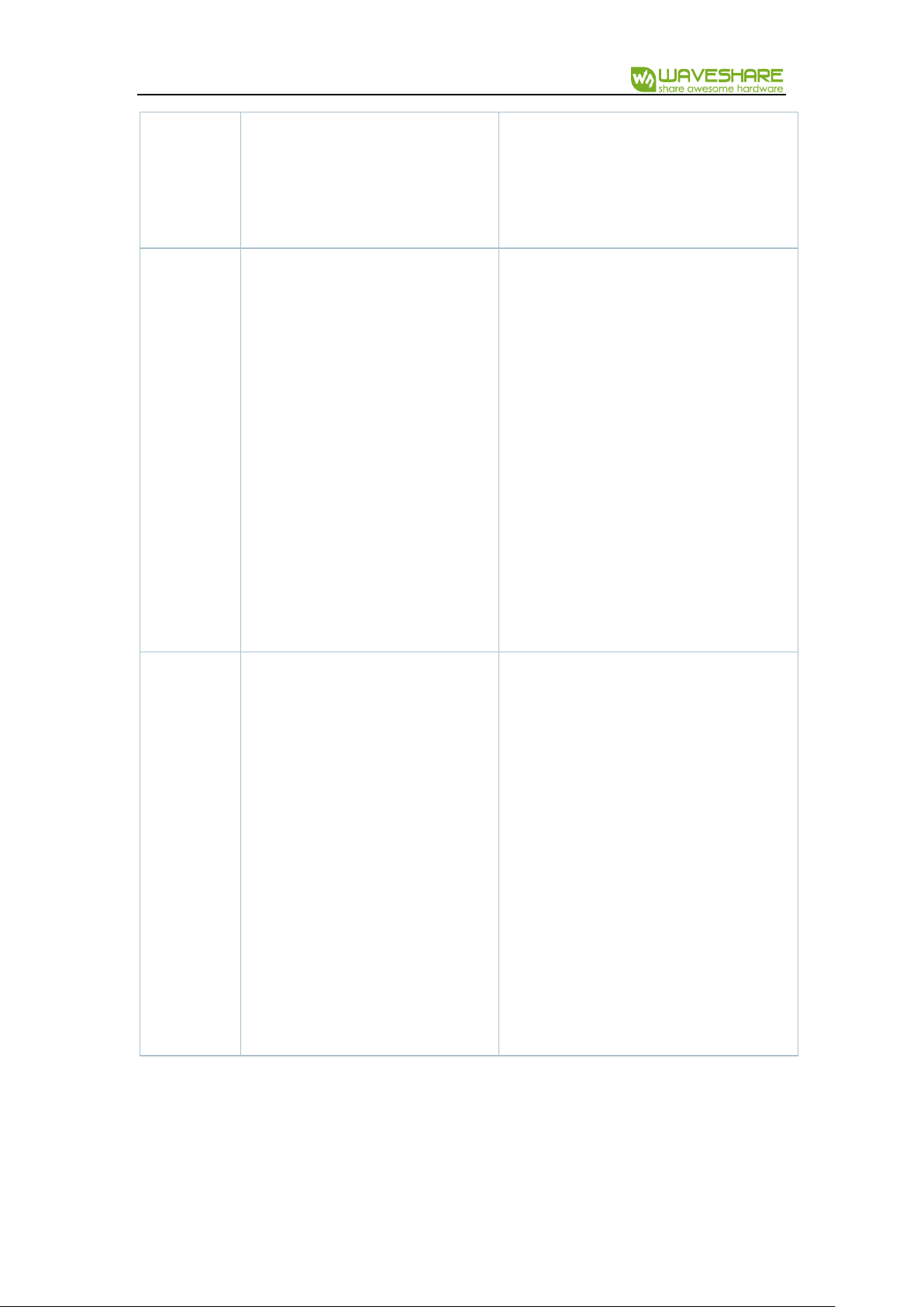
Find your type of display in table 1 and set the trigger to right position:
Trigger state
e-Paper type
A
1.54 inch, 2.13 inch, 2.9 inch
B
1.54 inch(b), 2.13 inch(b), 2.7 inch, 2.7 inch(b), 2.9 inch(b), 4.2 inch, 4.2
inch (b), 7.5 inch(b), 7.5 inch(b)
THE CLIENT-SIDE APPLICATION
The client-side application consists of 4 files: index.html, styles.css, processing.js (divided on
3 parts: ~A.js, ~B.js, ~C.js) and uploading.js. It allows the opening an image file, correcting its
color gamma according to a display’s type, and uploading the result to the server-side
application.
e-Paper ESP8266 Driver Board User Manual
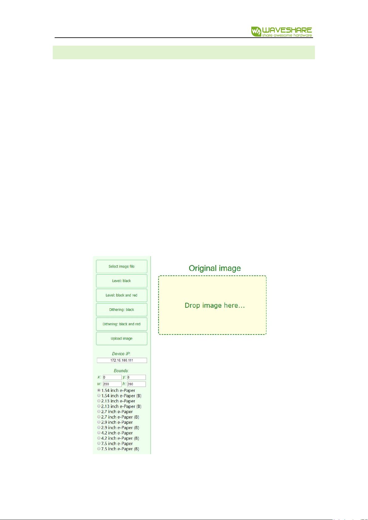
USER INTERFACE
The application user interface has following controls (figure 5):
Select image file
– opens the file browser;
Level: black, Level: black and red, Dithering: black, Dithering: black and red
- make a
new picture based on opened image with proper size and colors;
Upload image
– makes a POST request with the type of e-Paper, sends it to the server-
side application and waits response ‘Ok’, sends the processed image part by part;
Device IP:
shows IP of server-side application;
Boudns
are source copying rectangle offset (X, Y) and display size (W, H) defined by radio
buttons:
1.5 inch e-Paper… 7.5 inch e-Paper(b)
;
Viewers:
Original image
(drag & drop control),
Processed image
(is empty initially).
Note:
Bounds W, H
and
Device IP
are supposed to be not editable and updated automatically
when you change e-Paper’s type or the server, but they are changeable to allow you to test the
software or to control a few boards just pasting their IP into
Device IP
text box.
e-Paper ESP8266 Driver Board User Manual
IMAGE PROCESSING
The client-side application provides two kinds of image processing: Level and Dithering.
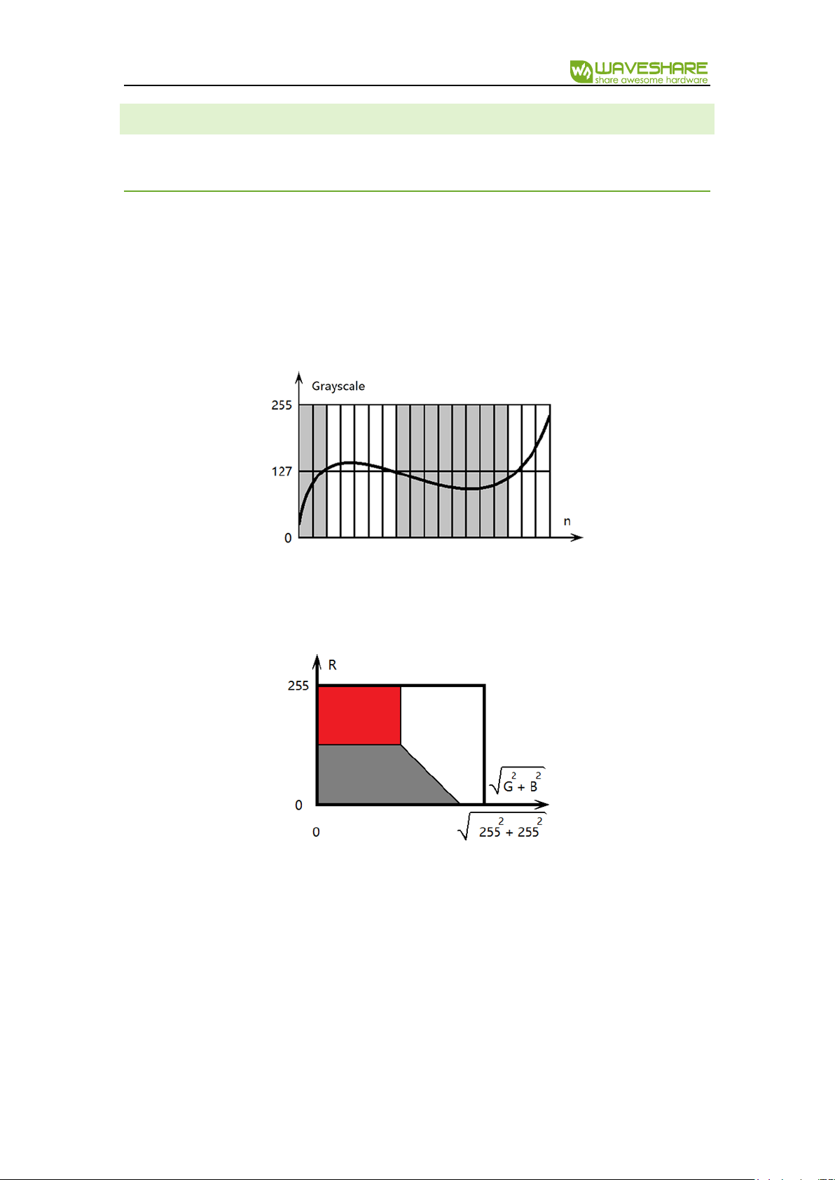
LEVEL
The Level supposes that that image can be divided on a few large regions, in which all of
pixels have color ‘close’ to one of available colors: black, white or red and ‘far’ to others available
colors. This kind of processing is suitable for 2- or 3-color schematics or texts.
For example, if pixel’s color of a grayscale image is equals and less than 127, the assigned
available color is black, otherwise is white (figure 6).
In case of colored image the green and blue channel are combined to green-blue or not-
red channel which is ‘orthogonal’ to the red one. On the color diagram (figure 7) it is shown that
pixels with high value of red channel and low value of green-blue channel is takes red color,
otherwise black or white as in previous example.
Mathematically the definition of color is based on the discrepancy calculation – the sum of
squares of channel differences between given and available colors. Pixels take available color
which has minimal discrepancy with their color. In the code snipped below the available colors
are stored in curPal array:

e-Paper ESP8266 Driver Board User Manual
DITHERING
In case of smooth colored pictures during the Level processing an image looses a lot of thin
details expressed by smooth gradient of colors situated close to each other in the color diagram.
The most of gradients cover large areas of pictures taken by camera, thus it is possible to
express some shades by mixing closest available colors on those areas.
Eyes feel the average color of pixels in a small area. It means there are more seeming
colors, but in other hand the picture seems noisy we well or as if it has low resolution. Good
algorithms of color the mixing can prevent pixilation (creating clearly seen small grain-like areas
in a picture). One of them is the Dithering.
The application uses the Floyd-Steinberg Dithering - most famous 2D error diffusion
formula (was published by Robert Floyd and Louis Steinberg in 1976). It diffuses errors according
the pattern shown in figure 8.
Here X - is an error (scalar/vector difference between original and available
grayscale/colored value of pixel). This error is distributed between right, right-bottom, bottom
and left-bottom pixels, is just added to their values with factors 7/16, 1/16, 5/16 and 3/16
respectively. Thus the average original color stays within this small group of pixels. The algorithm
doesn’t change left, left-top, top and right-top pixels because they are already corrected at

e-Paper ESP8266 Driver Board User Manual
previous iteration of the algorithm. See examples of the photographic image processing in
figures 9, 10 and 11.
DATA TRANSMISSION PROTOCOL
The ESP8266 module is intended for sending short messages and can be used neither for
video streaming, nor for sending large pictures. In this case the protocol allowing the data
dividing and sending it part by part must be used. If you don’t know well about Wi-Fi
functionality or can’t use it by some reason, but need to develop a tool for the file transmission
Figure 2 Original Image
Figure 1 “LEVEL Black” and “LEVEL RED and Black”
Figure 3 “Dithering: black” and “Dithering: black and red”

e-Paper ESP8266 Driver Board User Manual
via HTML page and Wi-Fi net in haste then you can use the solution described in this document.
It is based on POST request data transmission, but isn’t “the bad practice” (as if it’s based on GET
request). Consider the data transmission mechanism of this solution, modificate it or add your
own functions/commands if you need.
CO MMANDS
The protocol of communication between image dividing code snippet on the client-side
and data receiving code at the server-side includes 4 commands:
EPDn – the initialization of n-type display (n is a character in range ‘a’..’l’);
LOAD – the image data loading (black and/or red channel);
NEXT – the switching from the black channel to the red one;
DONE – the refreshing of display and turning into the deep sleep mode.
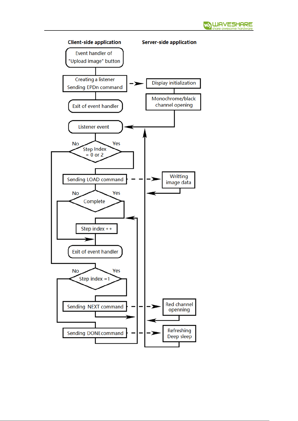
INITI AL I ZATI ON ALGORITHM
As it is shown in the diagram (figure 12), the event handler of “Upload image” button
creates an object for sending commands and listening responses from server, sends EPDn-
command. The server-side application receives the EPDn-command, initializes the e-Paper
display and open monochrome or black channel for writing.
The memory writing commands (EPDn and NEXT) for white-black display is
EPD_SendCommand(0x24);//WRITE_RAM
and for white-black-red display is (black and red channels correspondently):
EPD_SendCommand(0x10); //DATA_START_TRANSMISSION_1,
EPD_SendCommand(0x13); //DATA_START_TRANSMISSION_2
,
but there are exceptions:
White-black displays 2.7 and 4.2 use the red channel (code 0x13) instead of
monochrome channel (code 0x24);
The display 7.5 loads the red and black data simultaneously.
Thus, when you copy code snippets from initialization functions pay attention how they write
image data into display’s memory!
e-Paper ESP8266 Driver Board User Manual
Important: before the first writing of the image data into a display, one of commands:
WRITE_RAM, DATA_START_TRANSMISSION_1 or DATA_START_TRANSMISSION_2 is required,

e-Paper ESP8266 Driver Board User Manual
but 2.13-display can load data line by line only. It means before the image data writing of each
line, the command WRITE_RAM must be executed.
DATA TRANSMISSION ALG O R I T H M
Every time the server gets some request, it sends the word “OK” (in case of known command),
otherwise the index html page. This response initiates
onload
event of the
xhReq
object and the
client-side application sends a command again according the step index
stInd
(see diagram
above and file
uploading.js
):
Here
epdInd
is the display type index n mentioned in EPDn command.
Note: for white-black displays steps 1 and 2 are missing.
The image data, which is sent as a POST request, is accumulated in the bytes buffer (see
buff.h
file of the server-side application):
Here 2050 >= (about 1000 bytes of data reliablely sent to ESP8266 module + about 15 bytes
in case of 3.12-display) x 2 chars per byte.
Note: You can send more data with the same size of the buffer, but this case you must
modificate
Buff__getByte
function at the server-side application (file
buff.h
) and
byteToStr
function at the client-side application (file
uploading.js
). Another way to increase the data
capacity of a request is to estimate auxiliary data of the request, but this way is complicate and
effective enogh as the first one.
Actually, there is function ReadStringUntil in Arduino, which can accumulate and return whole
string of a request, but it works very slovely. This code solution describes a while-loop, where
the POST-request is accumulated character by character and every iteration of the the loop has
the signature (last 4 characters in case of command and more characters in case of a file name
as “styles.css” or “uploading.js”) checking to define what the client needs to obtain:

e-Paper ESP8266 Driver Board User Manual
DATA PIXEL FORMAT
When your browser opens an image file, the pixel format is 24 bpp by default. The image
processing reduces it to 1 bpp (white-black display):
0 – white;
1 – black;
or 2 bpp (white-black-red display):
0 – white;
1 – black;
2 – gray (1.54 inch b-type only);
3 – red.

e-Paper ESP8266 Driver Board User Manual
Before the
xhReq
object sends a POST-request to the server, the client-side application packs
image data into bytes or words. The bits order in these bytes/wordas is native display memory
order or is suitable for fast conversion into the native orser. The table 2 shows this changes from
the start of conversion to the writing of data into display’s memory:
Display type
(channel)
Transmission format
(p – pixel, b - bits)
Native format
1.54 (black)
1.54b (red)
2.13 (black)
2.13b (both)
2.7b (both)
2.9 (black)
2.9b (both)
4.2 (black)
4.2b (both)
p:01234567 - b:76543210
0 – black or red;
1 – white.
p:01234567 - b:76543210
0 – black or red;
1 – white.
Comment: there are no any changes
2.7
p:01234567 - b:76543210
0 – black;
1 – white.
p:01234567 - b:76543210
0 – white;
1 – black ().
Comment: bitwise inversion
7.5
p:01234567 - b:76543210
0 – black or red;
1 – white.
p:0 - b:7,6,5,4 (7 is high, 4 is low);
p:1 – b:3,2,1,0;
p:2 – b:15,14,13,12;
p:3 – b:11,10,9,8;
e-Paper ESP8266 Driver Board User Manual
0000 (0) – black;
0011 (3) – white.
1.54b (black)
p:0 – b:1,0;
p:1 – b:3,2;
p:2 – b:5,4;
p:3 – b:7,6;
00 (0) – black;
01 (1) – white;
10 (2) – gray;
11 (3) – red, is read as 10 (2).
p:0 – b:7,6;
p:1 – b:5,4;
p:2 – b:3,2;
p:3 – b:1,0;
00 (0) – black;
01 (1) – gray;
11 (3) – white;
7.5b
p:0 – b:1,0;
p:1 – b:3,2;
p:2 – b:5,4;
p:3 – b:7,6;
00 (0) – black;
01 (1) – white;
10 (2) – gray;
11 (3) – red.
p:0 - b:7,6,5,4 (7 is high, 4 is low);
p:1 – b:3,2,1,0;
p:2 – b:15,14,13,12;
p:3 – b:11,10,9,8;
0000 (0) – black;
0011 (3) – white;
0100 (4) – red.
e-Paper ESP8266 Driver Board User Manual
HARDWA RE
The board of the E-Paper Image Loader is developed to control an e-Paper display by Wi-
Fi net, but the EPS-8266 module allows performing a lot of other useful functions the same time:
keep loaded images in SD-card or external flash memory, get data from sensors and display
them in e-Paper, and so on. All of additional components need correspondent circuits: the e-
Paper display circuits are on the board, other possible circuits are connected by 2 series of pins
at the bottom of the board.
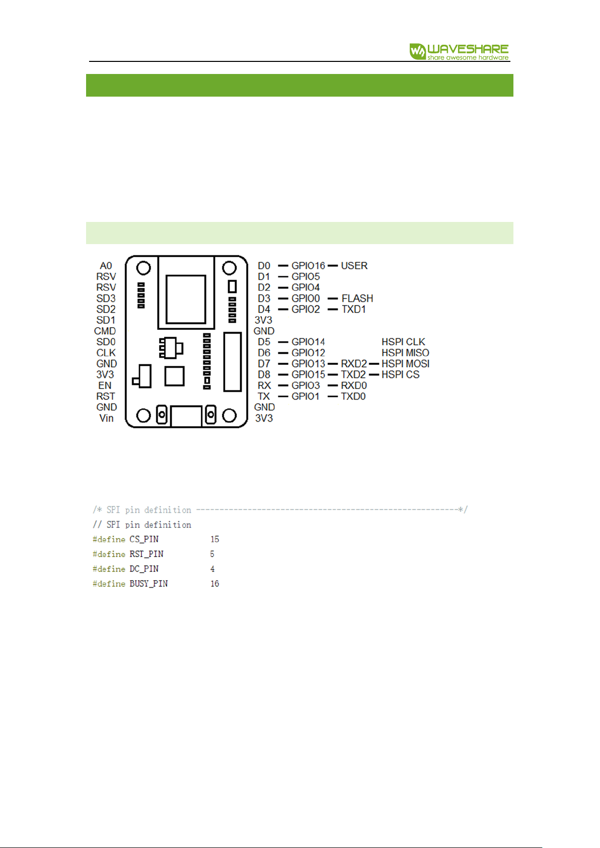
PINO UT
If you need to use some of EPS8266-Arduino project, just detouch your display, because it
is connected to pins:
If a display is detouched form the board, their display circuits situated in it don’t make any
influence on the ESP-8266 circuits.
e-Paper ESP8266 Driver Board User Manual
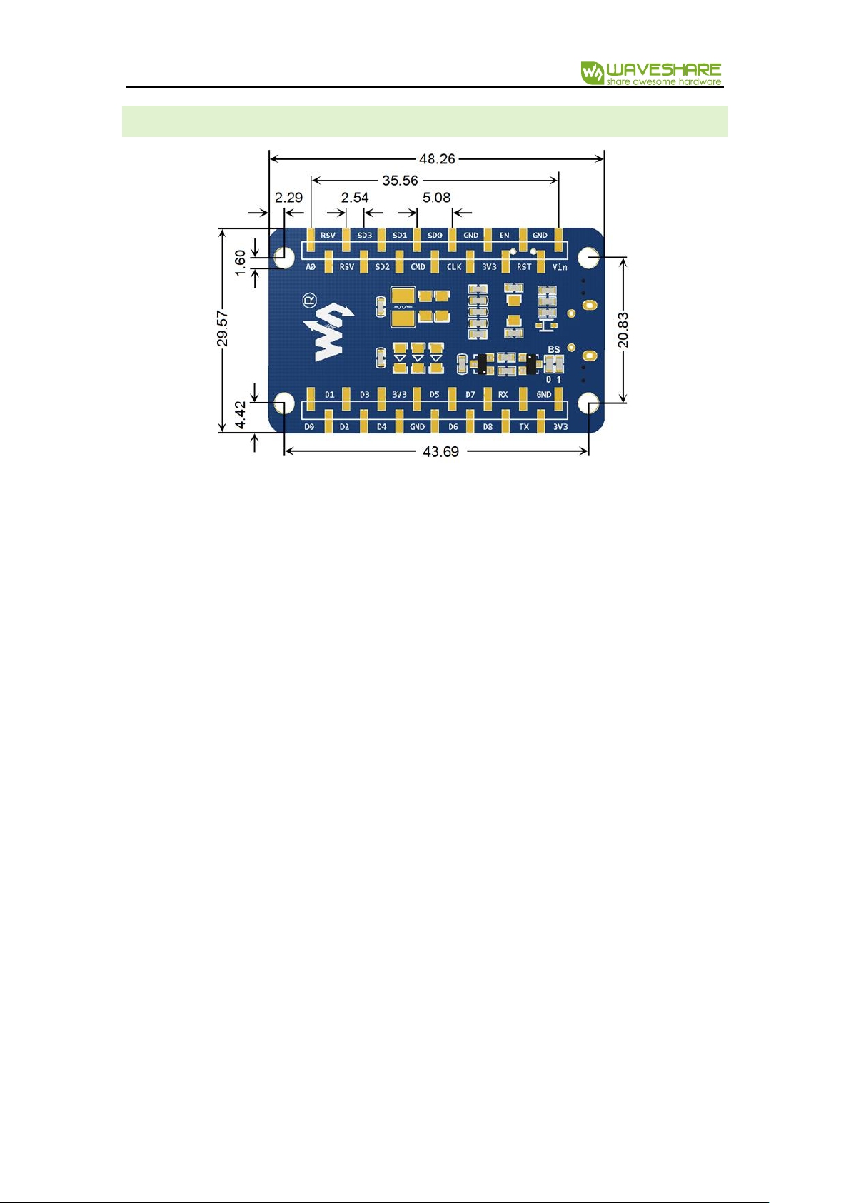
OUTLINE DIMENSION
 Loading...