


NRF52840 Eval Kit User Manual
Vision: V1.0.1 Date: 2019.01.19 1 / 72
NRF52840 Eval Kit
User Manual

NRF52840 Eval Kit User Manual
Vision: V1.0.1 Date: 2019.01.19 2 / 72
CONTENT
Chapter 1. Overview ..................................................................................................................................5
what’s on Board ..............................................................................................................................5
Chapter 2. Setup Developing Environment ......................................................................................7
Install Keil and related Pack ...........................................................................................................7
Install SEGGER Embedded Studio for ARM 4.10a ..................................................................7
Serial driver install .............................................................................................................................7
Install Jlink driver ...............................................................................................................................8
Install nRFx-Command-Line-Tools ..............................................................................................9
Install APP .............................................................................................................................................9
Peripherals demo ............................................................................................................................ 10
Hardware connection ............................................................................................................ 10
Download samples without Softdevice .......................................................................... 11
Download Samples with Softdevoce ............................................................................... 13
Chapter 3. Creating new project ........................................................................................................ 15
Project template .............................................................................................................................. 15
Create a new project ...................................................................................................................... 16
Chapter 4. Controling LED ................................................................................................................... 20
Codes .................................................................................................................................................. 20
Hardware Connection ................................................................................................................... 21
Chapter 5. UART ...................................................................................................................................... 23
Codes .................................................................................................................................................. 23

NRF52840 Eval Kit User Manual
Vision: V1.0.1 Date: 2019.01.19 3 / 72
Hardware ........................................................................................................................................... 27
Chapter 6. SPI ........................................................................................................................................... 29
Loopback testing ............................................................................................................................ 29
Drive OLED ........................................................................................................................................ 30
Hardware ........................................................................................................................................... 31
Chapter 7. I2C ........................................................................................................................................... 33
Scanning Slave devices ................................................................................................................. 33
Read data from BME280 .............................................................................................................. 33
Read data from MPU6050 ........................................................................................................... 37
Hardware ........................................................................................................................................... 38
Chapter 8. NFC ......................................................................................................................................... 41
Codes .................................................................................................................................................. 41
Hardware ........................................................................................................................................... 43
Chapter 9. Bluetooth .............................................................................................................................. 44
Preparation........................................................................................................................................ 44
Install softdevice ............................................................................................................................. 44
Bluetooth serial transparent ....................................................................................................... 44
Bluetooth against losing .............................................................................................................. 47
Bluetooth Beacon (Support WeChat Shake) ......................................................................... 49
Wireless Mouse ............................................................................................................................... 52
Wireless Keyboard .......................................................................................................................... 53
CSCS .................................................................................................................................................... 55

NRF52840 Eval Kit User Manual
Vision: V1.0.1 Date: 2019.01.19 4 / 72
Bluetooth Master- Cardiotachometer ..................................................................................... 56
Master-Slaver-BLE Relay .............................................................................................................. 58
Chapter 10. MESH ................................................................................................................................... 62

NRF52840 Eval Kit User Manual
Vision: V1.0.1 Date: 2019.01.19 5 / 72
CHAPTER 1. OVERVIEW
NRF52840 Eval Kit is a development/evaluation kit based on nRF52840, features
Arduino / Raspberry Pi connectivity, and several common peripherals.
It supports the new generation Bluetooth 5.0, compared to Bluetooth 4.0, the data
rate is twice, up to 2Mbps, the transfer distance is quadruple. Based on the ARM
Cortex-M4F architecture, the CPU frequency achieves up to 64MHz. Bluetooth MESH1
and 2.4GHz radio are also available, that means higher performance, and more
suitable applications.
Thanks to the onboard Arduino / Raspberry Pi compatible headers, both Arduino
shields and Raspberry Pi HATs can be attached at the same time, make it easy to use
more expansion resources.
WHAT’ S ON BOARD
1
At least three NRF52849 modules are required for Bluetooth MESH networking

NRF52840 Eval Kit User Manual
Vision: V1.0.1 Date: 2019.01.19 6 / 72
1. Arduino headers: for connecting
Arduino shields
2. Raspberry Pi GPIO header: for
connecting Raspberry Pi HATs
3. USB TO UART interface
4. USB port: the USB port of nRF52840
5. 4PIN SWD debugging interface:
for connecting ARM Debugger to
program / debug
6. 3.3V/5V power input/output:
provides power output OR powered
from external power supply
7. Core52840: nRF52840 core module
8. CP2102: USB TO UART converter
9. Buzzer
10. RT9193-33: 3.3V voltage regulator
11. Optical sensor
12. Keys: RESET and USER KEY
13. LEDs
PWR: power indicator
RXD/TXD: nRF52840 UART RX/TX
indicator
LED1~LED4: USER LEDs
14. Power switch
USB: powered from USB connection
Battery: powered from CR2032
battery
15. NFC antenna connector
16. TF card slot
17. CR2032 battery holder
18. Jumpers
Short the jumpers: connect the
onboard peripherals to I/Os in
example code
Open the jumpers: connect to
custom I/Os via jumper wires
19. Current testing pads: 0Ω resistor is
soldered by default, remove the
resistor to test current of the board

NRF52840 Eval Kit User Manual
Vision: V1.0.1 Date: 2019.01.19 7 / 72
CHAPTER 2. SETUP DEVELOPING ENVIRONMENT
Generally, we use nRFgo Studio software to programming NRF52840, however,
because of the compatibility of JLink driver, which is the driver of programmer of nRF
series. Herein we use CLI to setup developing environment for nRF52840 instead of
nRFgo Studio.
INSTALL KEIL AND RELATED PACK
Download Keil from its website and install. Note that Keil requires license,
otherwise it can only be used to compile codes which is smaller than 256kB.
After installing, you should also install related Packs. The NRF52840 pack was
already included in resources2, run NordicSemiconductor.nRF_DeviceFamilyPack.8.17.0
to install it.
INSTALL SEGGER EMBEDDED STUDIO FOR ARM 4.10A
This tool is only required for Bluetooth MESH examples. You can skip this part if
you do not use MESH.
You can download the package from resources and install it without license.
SERIAL DRIVER INSTAL L
The Evaluation board has integrated CP2102 module, which is used for TTL to USB
converting. To properly use serial port, you need to install CP2102 driver in your PC. If
you have installed it before, skip this part.
The CP2102 driver is included in resources, choose one according to your OS.
2
You can find them on Waveshare Wiki: https://www.waveshare.com/wiki/NRF52840_Eval_Kit
NRF52840 Eval Kit User Manual
Vision: V1.0.1 Date: 2019.01.19 8 / 72
⚫ Double-click installer “CPCP210xVCPInstaller_xxx” to run it
⚫ Clock next to finish installing
After installing, you can find that a new serial device is recognized under
Computer->Manager->Devices Manager-> COM and LPT after you connect the
evaluation board to PC.
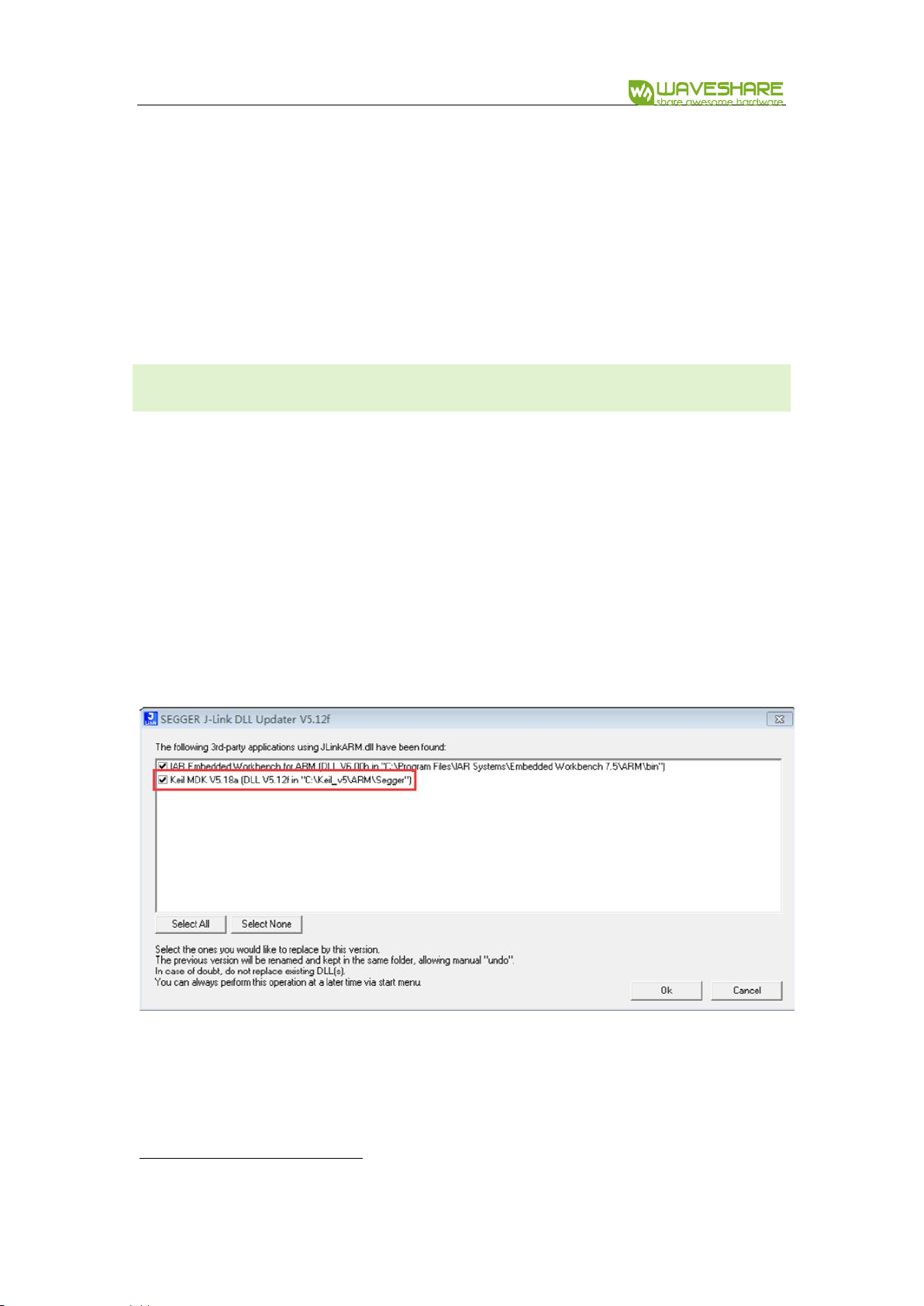
INSTALL JLINK DRIVER
JLink programmer is used to programming NRF52840. It can also be used to erase
NRF52840Flash and upload Bluetooth Softdevices3 with nRF5x-Command-Line-Tools.
We recommend you use V6.22 version or above, otherwise, the driver may cannot be
recognized. The JLink driver is included in resources, you can search and download it.
If you have installed Keil before JLink driver, don’t forget to check the option to
cover it as below:
3
Softdevices are protocol stacks for nRF series

NRF52840 Eval Kit User Manual
Vision: V1.0.1 Date: 2019.01.19 9 / 72
INSTALL NRFX-COMMAND-LINE-TOOLS
The tool can be downloaded from resources. Download and install it. After
installing, open console, and input nrfjprog -v to check the tools. It should be as below
if you install the tool successfully.
INSTALL APP
App should be installed in mobile phones for debugging.
nRF Connect: Common debugging tool of mobile phone. With this APP, use can
get the original data. nRF Connect can display RSSI curve, supports multiply slave
devices, has high compatibility and is commonly used.
nRF Toolbox: BLE tool. Toolbox is generally used for part of experiments, it has
GUI like thermometer, cardiotachometer. However, it can only be used for some of
experiments and it is not much stable.

NRF52840 Eval Kit User Manual
Vision: V1.0.1 Date: 2019.01.19 10 / 72
PERIPHERALS DEMO
Finish the developing environment setup, you now can try with some demo. Herein
using the newest SDK(SDK 15.2), which support Bluetooth 5.0
There are examples in SDK, which can be divided to two kinds, one of them can
run without Softdevice and another are based on Softdevice. The demo which does
not need Softdevice generally located in
nRF5_SDK_15.2.0_9412b96\examples\peripheral\
HARDWARE CONNECTION
⚫ Connect J-Link programmer to NRF52840 Eval kit and PC
⚫ Connect NRF52840 Eval Kit to PC or other external power adapter
⚫ Pull the jumper of LED3, and wire L3 to P1.054
4
LED3 isn’t compatible with official SDK, so we should re-connect it when test Blinky sample

NRF52840 Eval Kit User Manual
Vision: V1.0.1 Date: 2019.01.19 11 / 72
DOWNLOAD SAMPLES WITHOUT SOFTDEVICE
We take Blinky as example, learn how to use peripherals examples of SDK. Click
blinky->pca10056->blank->arm5_no_packs->blink_pca10056.uvoptx to open the
project. Compiling it:
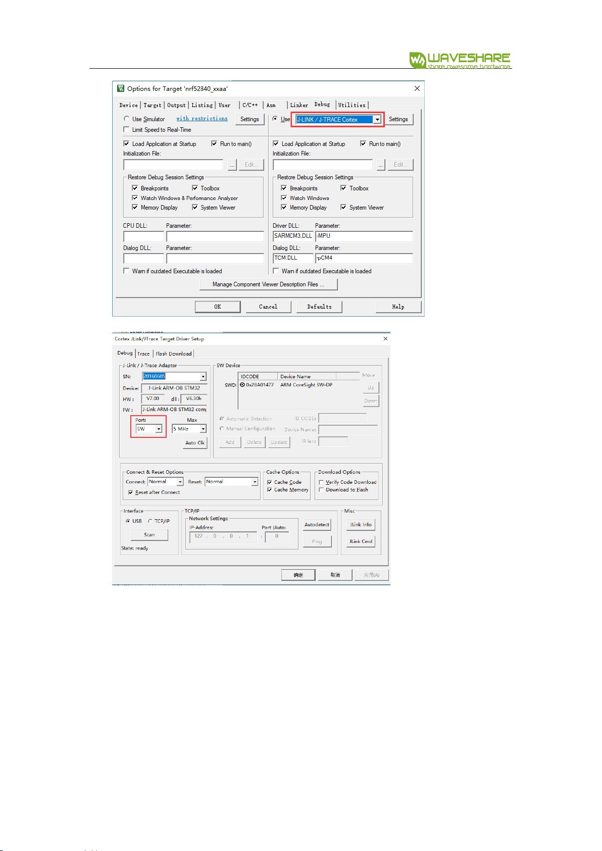
Generally, it can be compiled successfully without error or warning. After
compiling, you should configure it:
Click Debug, choose J-Links/J-Trace Cortex as debugger. Debug->Settings set
Port to SW
NRF52840 Eval Kit User Manual
Vision: V1.0.1 Date: 2019.01.19 12 / 72
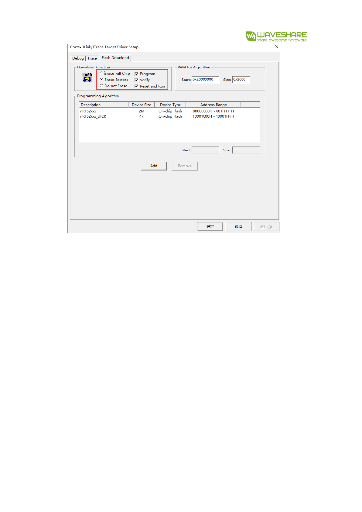
Then click Flash Download, check the options as below and confirm by clicking
OK.
NRF52840 Eval Kit User Manual
Vision: V1.0.1 Date: 2019.01.19 13 / 72
DOWNLOAD SAMPLES WITH SOFTDEVOCE
Different with samples like the blinky, you should first download softdevices,
which Bluetooth demo codes are based on. Herein we take app_uart as example to
show you how to program such demos.
⚫ First, we need to erase NRF52840 flash: Open CMD, connect NRF52840 to PC and
using ARM Debugger(JLink) for programming. Type command to erase NRF52840

NRF52840 Eval Kit User Manual
Vision: V1.0.1 Date: 2019.01.19 14 / 72
as below:
⚫ Download Softdevice. Click
nRF5_SDK_15.2.0_9412b96->examples->ble_peripheral->ble_app_uart->pca10056
->s140->arm5_no_packs-> ble_app_uart_pca10056_s140.uvprojx to open the
project. Choose flash_s140_nrf52_6.1.0_softdevice:
⚫ Download the application code like blinky sample.

NRF52840 Eval Kit User Manual
Vision: V1.0.1 Date: 2019.01.19 15 / 72
CHAPTER 3. CREATING NEW PROJECT
SDK should be used for NRF52840 developing, we take common SDK5 as example
to show you how to create a project.
The SDK used herein is SDK V15.2, there is also template for reference:
nRF5_SDK_15.2.0_9412b96\examples\ble_peripheral\ble_app_template\pca10056\s140
\arm5_no_packs\ble_app_template_pca10056_s140.uvprojx
PROJECT TEMPLATE
Generally, the project should include:
⚫ DRIVER: Drivers of hardware peripherals are saved in this directory, like driver of
MPU6050 created by users
⚫ SDK: SDK files copied from official SDK, like:
5
There are specific SDK used for Zigbee, Thread and Mesh sevices

NRF52840 Eval Kit User Manual
Vision: V1.0.1 Date: 2019.01.19 16 / 72
There are so many files included in SDK, and we only use some of them for certain
project. Most of libraries are included in components, external contains third party
libraries like freertos library and so on. Old drivers are saved to folder integration
and modules contains the new drivers.
⚫ TEMP: Intermediate files generated while compiling. The files in this folder can be
deleted.
⚫ USER: User files
Generally, files in folders SDK, DRIVER and TEMP are same for different project, what
we need to do is create user files and save them to USER.
CREATE A NEW PROJECT
Create a directory to save project files and copy libraries files to it.
You can google about how to create a new Keil project. Herein we take about
some notices when creating new project.

NRF52840 Eval Kit User Manual
Vision: V1.0.1 Date: 2019.01.19 17 / 72
⚫ The drivers of user peripherals should be saved in DRIVER folder
⚫ The projects created should be saved under USER, and please notice the project
name
⚫ The application files are usually saved under the path: USER/[Project
file]/APPLICATION/

NRF52840 Eval Kit User Manual
Vision: V1.0.1 Date: 2019.01.19 18 / 72
⚫ The Keil project file is saved in IDE folder
⚫ Save OBJ files to TEMP folder

NRF52840 Eval Kit User Manual
Vision: V1.0.1 Date: 2019.01.19 19 / 72
⚫ You had better set the project tree same as official projects.
⚫ Notice the PACK version you use, make sure it is same as official examples
For more details, please refer to official examples.

NRF52840 Eval Kit User Manual
Vision: V1.0.1 Date: 2019.01.19 20 / 72
CHAPTER 4. CONTROLING LED
In this chapter, we will instruct how to configure GPIO and control LED. The
examples used herein is 001_LED.
CODES
Open led.h files, you can find that the GPIO and related control functions are defined
in this header file:
#ifndef __LED_H__
#define __LED_H__
#include "nrf.h"
#include "nrf_gpio.h"
#define LED0 NRF_GPIO_PIN_MAP(0,13)
#define LED1 NRF_GPIO_PIN_MAP(0,14)
#define LED2 NRF_GPIO_PIN_MAP(0,19)
#define LED3 NRF_GPIO_PIN_MAP(0,16)
void LED_On(uint32_t led_number);
void LED_Off(uint32_t led_number);
#endif
Functions defined in header file will be realized in led.c file:
#include "led.h"
void LED_On(uint32_t led_number)
{
nrf_gpio_cfg_output(led_number);
nrf_gpio_pin_clear(led_number);
}
void LED_Off(uint32_t led_number)
{
nrf_gpio_cfg_output(led_number);
nrf_gpio_pin_set(led_number);
}
LED_On(led_number): Turn the LED on
LED_Off(led_number): Turn the LED off

NRF52840 Eval Kit User Manual
Vision: V1.0.1 Date: 2019.01.19 21 / 72
And finally, the functions are called in main file to keep turning four LEDs on for
500ms then turning them off for 500ms.
int main(void)
{
while (true)
{
LED_On(LED0);
LED_On(LED1);
LED_On(LED2);
LED_On(LED3);
nrf_delay_ms(500);
LED_Off(LED0);
LED_Off(LED1);
LED_Off(LED2);
LED_Off(LED3);
nrf_delay_ms(500);
}
}
HARDWARE CONNECTION
According to the codes above we know that, the four LEDs controlled should be
connected to P0.13, P0, 14, P0.19, P0.16 separately as table:
UART
GPIO
LED1
P0.13
LED2
P0.14
LED3
P1.09
LED4
P0.16
In official SDK, LED3 is connected to P0.15 which is not compatible with official
examples. If you want to use the official SDK and LED3, you need to change it to P1.09.

NRF52840 Eval Kit User Manual
Vision: V1.0.1 Date: 2019.01.19 22 / 72
The schematic of Eval board is as below:
Header 4x2 are jumpers on board:
If you use official SDK, don’t forget to pull L3 jumper and wire it to P0.15 (Do not
require if you use 001_LED).

NRF52840 Eval Kit User Manual
Vision: V1.0.1 Date: 2019.01.19 23 / 72
CHAPTER 5. UART
In this chapter, we describe about how to use UART interface of NRF52840. The
example used herein is 003_UART. With the example, data can be sent from NRF52840
to UART interface, and LED on eval board will turn on/off when receive corresponding
data from UART interface.
CODES
uart.h
#ifndef _UART_H_
#define _UART_H_
#include "nrf.h"
#include "nrf_gpio.h"
#include "app_uart.h"
#include "nrf_uart.h"
#define RX_PIN_NUMBER NRF_GPIO_PIN_MAP(0,8)
#define TX_PIN_NUMBER NRF_GPIO_PIN_MAP(0,6)
#define CTS_PIN_NUMBER NRF_GPIO_PIN_MAP(0,7)
#define RTS_PIN_NUMBER NRF_GPIO_PIN_MAP(0,5)
#define UART_HWFC APP_UART_FLOW_CONTROL_DISABLED
#define MAX_TEST_DATA_BYTES (15U)
#define UART_TX_BUF_SIZE 256
#define UART_RX_BUF_SIZE 256
extern app_uart_comm_params_t comm_params;
void uart_error_handle(app_uart_evt_t * p_event);
#endif
uart.c:
#include "uart.h"

NRF52840 Eval Kit User Manual
Vision: V1.0.1 Date: 2019.01.19 24 / 72
app_uart_comm_params_t comm_params =
{
RX_PIN_NUMBER,
TX_PIN_NUMBER,
RTS_PIN_NUMBER,
CTS_PIN_NUMBER,
UART_HWFC,
false,
NRF_UART_BAUDRATE_115200
};
void uart_error_handle(app_uart_evt_t * p_event)
{
if (p_event->evt_type == APP_UART_COMMUNICATION_ERROR)
{
APP_ERROR_HANDLER(p_event->data.error_communication);
}
else if (p_event->evt_type == APP_UART_FIFO_ERROR)
{
APP_ERROR_HANDLER(p_event->data.error_code);
}
}
main.c:
#include "nrf.h"
#include <stdio.h>
#include <stdint.h>
#include <stdbool.h>
#include "app_uart.h"
#include "app_error.h"
#include "nrf_delay.h"
#include "nrf_uart.h"
#include "nrf_uarte.h"
#include "led.h"
#include "uart.h"
/**
* @brief Function for main application entry.
*/
int main(void)
{

NRF52840 Eval Kit User Manual
Vision: V1.0.1 Date: 2019.01.19 25 / 72
uint32_t err_code;
APP_UART_FIFO_INIT(&comm_params,UART_RX_BUF_SIZE,UART_TX_BUF_SI
ZE,uart_error_handle,APP_IRQ_PRIORITY_LOWEST,err_code);
APP_ERROR_CHECK(err_code);
printf("\r\nUART example started.\r\n");
while (true)
{
uint8_t cr;
//Get Data from the port!
while (app_uart_get(&cr) != NRF_SUCCESS);
//Then put data to the port
while (app_uart_put(cr) != NRF_SUCCESS);
switch (cr)
{
case '1':
{
printf("\r\n LED0 ON \r\n");
LED_On(LED0);
break;
}
case '2':
{
printf("\r\n LED0 OFF \r\n");
LED_Off(LED0);
break;
}
case '3':
{
printf("\r\n LED1 ON \r\n");
LED_On(LED1);
break;
}
case '4':
{
printf("\r\n LED1 OFF \r\n");
LED_Off(LED1);
break;
}
case '5':

NRF52840 Eval Kit User Manual
Vision: V1.0.1 Date: 2019.01.19 26 / 72
{
printf("\r\n LED2 ON \r\n");
LED_On(LED2);
break;
}
case '6':
{
printf("\r\n LED2 OFF \r\n");
LED_Off(LED2);
break;
}
case '7':
{
printf("\r\n LED3 ON \r\n");
LED_On(LED3);
break;
}
case '8':
{
printf("\r\n LED3 OFF \r\n");
LED_Off(LED3);
break;
}
case 'q':
{
printf("\r\n Exit! \r\n");
while (true);
}
case 'Q':
{
printf("\r\n Exit! \r\n");
while (true);
}
default:
{
printf("\r\nPlease input correct command\r\n");
break;
}
}
}
}

NRF52840 Eval Kit User Manual
Vision: V1.0.1 Date: 2019.01.19 27 / 72
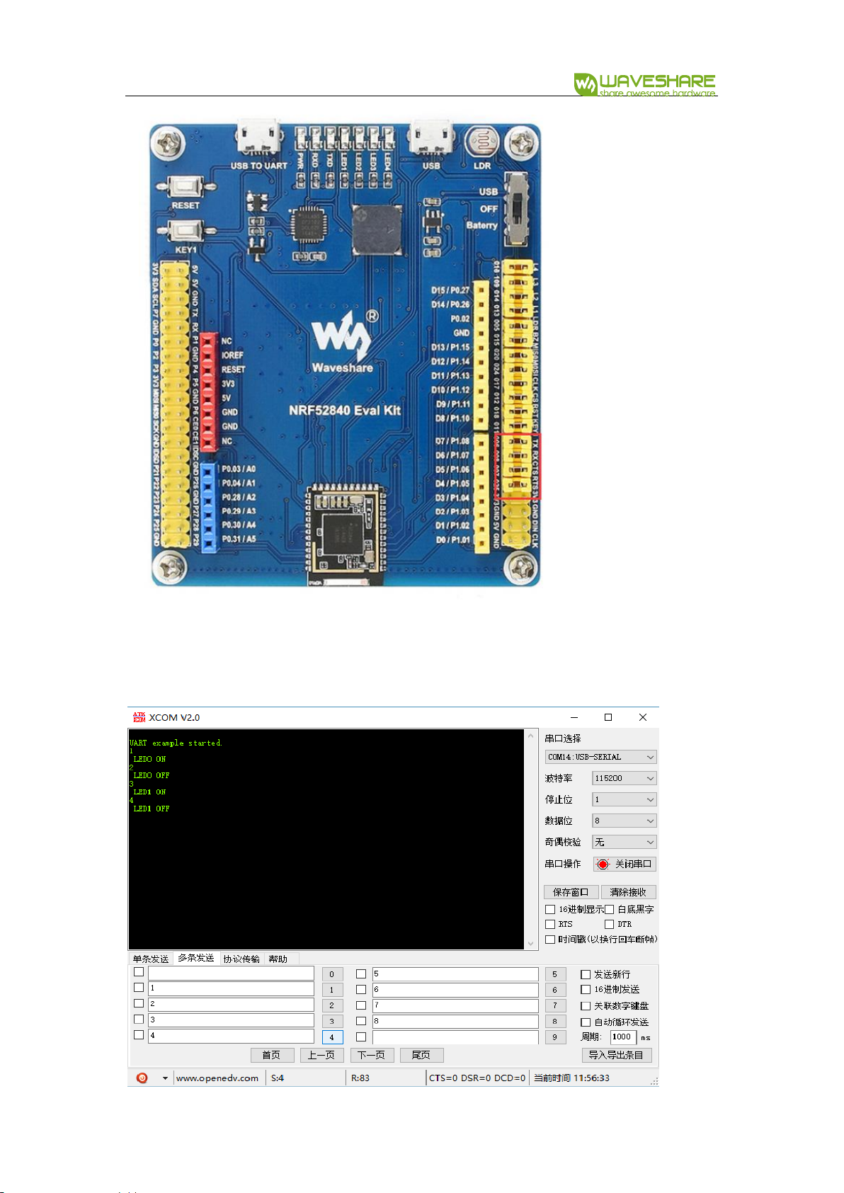
The serial is redirected in the codes, for using printf function to print data to uart
interface. In the main.c, serial port will keep receiving data, and if corresponding data
are received, LEDs will behavior according to it.
When 1 is received, LED1 is on, and turned off if receiving 2. Turn LED2 on if 3 and
turn off if 4 similarly.
HARDWARE
The schematic of serial part is as below:
H1 and H2 are jumpers of UART pins. CP2102 is accessed to NRF52840 only when
jumpers H1 and H2 are inserted.
UART
GPIO
CPTX
P0.06
CPRX
P0.08
CPRTS
P0.25
CPCTS
P0.07
NRF52840 Eval Kit User Manual
Vision: V1.0.1 Date: 2019.01.19 28 / 72
【Note】In official SDK, CPRTS is defined as P0.05, however, CPRTS is connected to
P0.25 on NRF52840 Eval kit. You need to modify the definition to P0.25 when using.

NRF52840 Eval Kit User Manual
Vision: V1.0.1 Date: 2019.01.19 29 / 72
CHAPTER 6. SPI
Examples used in this chapter: 004_SPI(Example), 005_SPI(OLED)
In this chapter, we will describe about how to use SPI interface of NRF52840, do
loopback testing and try to drive a 0.96inch OLED module.
LOOPBACK TESTING
main.c
#include "nrf_drv_spi.h"
#include "nrf_gpio.h"
#include "app_util_platform.h"
#include "nrf_delay.h"
#include "app_error.h"
#include <string.h>
#include "nrf_log.h"
#include "nrf_log_ctrl.h"
#include "nrf_log_default_backends.h"
#include "spi.h"
int main(void)
{
APP_ERROR_CHECK(NRF_LOG_INIT(NULL));
NRF_LOG_DEFAULT_BACKENDS_INIT();
nrf_drv_spi_config_t spi_config = NRF_DRV_SPI_DEFAULT_CONFIG;
spi_config.ss_pin = CS_PIN;
spi_config.miso_pin = MISO_PIN;
spi_config.mosi_pin = MOSI_PIN;
spi_config.sck_pin = SCK_PIN;
/*
Doesn't print what to send or what received in SPI
*/
//APP_ERROR_CHECK(nrf_drv_spi_init(&spi, &spi_config, NULL,
NULL));
/*
Print what to send or what received in SPI
*/
APP_ERROR_CHECK(nrf_drv_spi_init(&spi, &spi_config,
spi_event_handler, NULL));
NRF52840 Eval Kit User Manual
Vision: V1.0.1 Date: 2019.01.19 30 / 72
NRF_LOG_INFO("SPI example started.");
NRF_LOG_FLUSH();
while (1)
{
memset(m_rx_buf, 0, m_length);
spi_xfer_done = false;
APP_ERROR_CHECK(nrf_drv_spi_transfer(&spi, m_tx_buf,
m_length, m_rx_buf, m_length));
while (!spi_xfer_done)
{
__WFE();
}
NRF_LOG_FLUSH();
nrf_delay_ms(500);
}
}
DRIVE OLED
When you drive OLED via SPI interface, you should notice that:
1. Do not use interrupt callback function when initializing SPI
/*
Doesn't print what to send or what received in SPI
*/
//APP_ERROR_CHECK(nrf_drv_spi_init(&spi, &spi_config, NULL,
NULL));
/*
Print what to send or what received in SPI
*/
APP_ERROR_CHECK(nrf_drv_spi_init(&spi, &spi_config,
spi_event_handler, NULL));
2. If you must to add interrupt codes, add delay to it.
void Single_Command(unsigned char cmd)
{
nrf_gpio_pin_clear(DC);
//if SPI is busy Frequently,delay here
nrf_delay_us(30);
spi_write(&cmd, sizeof(cmd));
}

NRF52840 Eval Kit User Manual
Vision: V1.0.1 Date: 2019.01.19 31 / 72
3. The most basic function of OLED driver is written and read functions as below:
write
void Single_Command(unsigned char cmd)
{
nrf_gpio_pin_clear(DC);
//if SPI is busy Frequently,delay here
//nrf_delay_us(30);
spi_write(&cmd, sizeof(cmd));
}
read
void Single_Data(unsigned char dt)
{
nrf_gpio_pin_set(DC);
//if SPI is busy Frequently,delay here
//nrf_delay_us(30);
spi_write(&dt, sizeof(dt));
}
HARDWARE
In hardware, the SPI interface of NRF52840 are pinout to Arduino compatible
interface.

NRF52840 Eval Kit User Manual
Vision: V1.0.1 Date: 2019.01.19 32 / 72
【Note】The pins used in example herein are different with official SDK, if you use
official SDK with NRF52840 Eval Kit, don’t forget to modify the pins
SPI
GPIO
SPI_CS
P1.12
SPI_MOSI
P1.13
SPI_MISO
P1.14
SPI_SCK
P1.15
Loopback testing
Data will be sent from MOSI and back from the MISO.
Drive OLED
The OLED will display image as below:

NRF52840 Eval Kit User Manual
Vision: V1.0.1 Date: 2019.01.19 33 / 72
CHAPTER 7. I2C
In this chapter, we will learn about how to use the I2C interface of NRF52840. There
are three examples, which are used here: 006_I2C(Scan Device), 007_I2C(BME280),
008_I2C(MPU6050 3D COUBE)
SCANNING SLAVE DEVICES
It keeps scanning the slave device address of those devices which are connected to
I2C bus.
for(address=1; address<=TWI_ADDRESSES; address++)
{
err_code = nrf_drv_twi_rx(&m_twi, address, &sample_data,
sizeof(sample_data));
if (err_code == NRF_SUCCESS)
{
detected_device = true;
device_address = address;
NRF_LOG_INFO("TWI device detected at address 0x%x.",
address);
NRF_LOG_FLUSH();
}
}
The code will scan slave devices address connected and print them.
READ DATA FROM BME280
BME280 is a module from Bosch that supports sense environmental temperature,
humidity and barometric pressure.
Write/read function from Bosch: https://github.com/BoschSensortec/BME280_driver
int8_t user_i2c_read(uint8_t dev_id, uint8_t reg_addr, uint8_t
*reg_data, uint16_t len)

NRF52840 Eval Kit User Manual
Vision: V1.0.1 Date: 2019.01.19 34 / 72
{
int8_t rslt = 0; /* Return 0 for Success, non-zero for failure
*/
/*
* The parameter dev_id can be used as a variable to store the
I2C address of the device
*/
/*
* Data on the bus should be like
* |------------+---------------------|
* | I2C action | Data |
* |------------+---------------------|
* | Start | - |
* | Write | (reg_addr) |
* | Stop | - |
* | Start | - |
* | Read | (reg_data[0]) |
* | Read | (....) |
* | Read | (reg_data[len - 1]) |
* | Stop | - |
* |------------+---------------------|
*/
return rslt;
}
int8_t user_i2c_write(uint8_t dev_id, uint8_t reg_addr, uint8_t
*reg_data, uint16_t len)
{
int8_t rslt = 0; /* Return 0 for Success, non-zero for failure
*/
/*
* The parameter dev_id can be used as a variable to store the
I2C address of the device
*/
/*
* Data on the bus should be like
* |------------+---------------------|
* | I2C action | Data |
* |------------+---------------------|
* | Start | - |
* | Write | (reg_addr) |
* | Write | (reg_data[0]) |
* | Write | (....) |
* | Write | (reg_data[len - 1]) |
* | Stop | - |

NRF52840 Eval Kit User Manual
Vision: V1.0.1 Date: 2019.01.19 35 / 72
* |------------+---------------------|
*/
return rslt;
}
Working with NRF52840, you can use its library to realize the write/read function:
int8_t user_i2c_read(u8 dev_id, u8 reg_addr, u8 *reg_data, u16 len)
{
ret_code_t err_code =
nrf_drv_twi_tx(&m_twi,dev_id,®_addr,1,false);
APP_ERROR_CHECK(err_code);
err_code = nrf_drv_twi_rx(&m_twi,dev_id,reg_data,len);
APP_ERROR_CHECK(err_code);
return err_code;
}
#define MAX_WRITE_LENGTH 200
int8_t user_i2c_write(u8 dev_id, u8 reg_addr, u8 *reg_data, u16
len)
{
ret_code_t err_code;
uint8_t write_data[MAX_WRITE_LENGTH];
if(len>MAX_WRITE_LENGTH-1)
{
err_code = 1;
return err_code;
}
write_data[0] = reg_addr;
memcpy(&write_data[1],reg_data,len);
err_code =
nrf_drv_twi_tx(&m_twi,dev_id,write_data,len+1,false);
APP_ERROR_CHECK(err_code);
return err_code;
NRF52840 Eval Kit User Manual
Vision: V1.0.1 Date: 2019.01.19 36 / 72
}
BME280 Initialization in main.c
struct bme280_dev dev;
int8_t rslt = BME280_OK;
dev.dev_id = BME280_I2C_ADDR_SEC;
dev.intf = BME280_I2C_INTF;
dev.read = user_i2c_read;
dev.write = user_i2c_write;
dev.delay_ms = user_delay_ms;
//before you init bme280, you can choose to do a selftest
rslt = bme280_crc_selftest(&dev);
if(rslt == 0)
{
NRF_LOG_INFO("BME280 self test pass\r\n");
NRF_LOG_FLUSH();
}
rslt = bme280_init(&dev);
if(rslt == 0)
{
NRF_LOG_INFO("Init Success\r\n");
NRF_LOG_FLUSH();
}
else
{
NRF_LOG_INFO("Init Fail,Please Check your address or the wire
you connected!!!\r\n");
NRF_LOG_FLUSH();
while(1);
}
/*
Using normal mode to read the data
*/
stream_sensor_data_normal_mode(&dev);
bme280_crc_selftest(): Self testing function
stream_sensor_data_normal_mode(&dev): Read data of bme280 and calculate. Use
bme280_get_sensor_data() and print_sensor_data() to read and print_sensor_data().

NRF52840 Eval Kit User Manual
Vision: V1.0.1 Date: 2019.01.19 37 / 72
READ DATA FROM MPU6050
This example is run to read MPU6050 data via I2C bus.
u8 IIC_Write_1Byte(u8 SlaveAddress,u8 REG_Address,u8 REG_data)
{
ret_code_t err_code = user_i2c_write(SlaveAddress, REG_Address,
®_data, 1);
return err_code;
}
u8 IIC_Read_1Byte(u8 SlaveAddress,u8 REG_Address,u8 *REG_data)
{
ret_code_t err_code = user_i2c_read(SlaveAddress, REG_Address,
REG_data, 1);
return err_code;
}
u8 IIC_Write_nByte(u8 SlaveAddress, u8 REG_Address, u8 len, u8
*buf)
{
ret_code_t err_code = user_i2c_write(SlaveAddress, REG_Address,
buf, len);
return err_code;
}
u8 IIC_Read_nByte(u8 SlaveAddress, u8 REG_Address, u8 len, u8 *buf)
{
ret_code_t err_code = user_i2c_read(SlaveAddress, REG_Address,
buf, len);
return err_code;
}
The basic functions are user_i2c_read() and user_i2c_write().

NRF52840 Eval Kit User Manual
Vision: V1.0.1 Date: 2019.01.19 38 / 72
HARDWARE
In hardware, the I2C interface are pinout to the Arduino compatible header.
I2C
GPIO
SCL_PIN
P0.27
SDA_PIN
P0.26
The I2C pins can be re-configured to others by modifying the codes:
#define SDA_PIN NRF_GPIO_PIN_MAP(0,26)
#define SCL_PIN NRF_GPIO_PIN_MAP(0,27)
【Note】Don’t forget to change hardware connection if you re-configure the pins.
After running codes, the data will be printed to serial port and display the I2C address
in OLED as below:

NRF52840 Eval Kit User Manual
Vision: V1.0.1 Date: 2019.01.19 39 / 72
⚫ Downloading 007_I2C(BME280) codes, data will be printed to OLED as below:

NRF52840 Eval Kit User Manual
Vision: V1.0.1 Date: 2019.01.19 40 / 72
⚫ Downloading 008_I2C(MPU6050 3D COUBE), Data will be printed as below(The 3D
figure display is not stable):

NRF52840 Eval Kit User Manual
Vision: V1.0.1 Date: 2019.01.19 41 / 72
CHAPTER 8. NFC
CODES
This example is used to starting mobile APP.
The name of Android Phone APP:
static const uint8_t m_android_package_name[] =
{'n', 'o', '.', 'n', 'o', 'r', 'd', 'i', 'c', 's',
'e', 'm', 'i', '.', 'a', 'n', 'd', 'r', 'o', 'i',
'd', '.', 'n', 'r', 'f', 't', 'o', 'o', 'l', 'b',
'o', 'x'};
The name of Windows Phone APP:
static const uint8_t m_windows_application_id[] =
{'{', 'e', '1', '2', 'd', '2', 'd', 'a', '7', '-',
'4', '8', '8', '5', '-', '4', '0', '0', 'f', '-',
'b', 'c', 'd', '4', '-', '6', 'c', 'b', 'd', '5',
'b', '8', 'c', 'f', '6', '2', 'c', '}'};
Initializing callback function, which will be execute when NFC objects are detected to
turn on LED0.
static void nfc_callback(void * p_context, nfc_t2t_event_t event,
const uint8_t * p_data, size_t data_length)
{
(void)p_context;
switch (event)
{
case NFC_T2T_EVENT_FIELD_ON:
bsp_board_led_on(BSP_BOARD_LED_0);
break;
case NFC_T2T_EVENT_FIELD_OFF:
bsp_board_led_off(BSP_BOARD_LED_0);
break;
default:
break;
}
}
NRF52840 Eval Kit User Manual
Vision: V1.0.1 Date: 2019.01.19 42 / 72
In main.c file, the process to start NFC are that:
1. Set interrupt callback function and initialize NFC:
2. Encode NFC information
3. Load NFC information to NFC end
4. Start NRF
int main(void)
{
uint32_t len;
uint32_t err_code;
//Init log
log_init();
//Init led
bsp_board_init(BSP_INIT_LEDS);
//set NFC with a callback
err_code = nfc_t2t_setup(nfc_callback, NULL);
APP_ERROR_CHECK(err_code);
//provide available buffer size for encoding function
len = sizeof(m_ndef_msg_buf);
//Encode launchapp message into buffer
err_code = nfc_launchapp_msg_encode(m_android_package_name,
sizeof(m_android_package_name),
m_windows_application_id,
sizeof(m_windows_application_id),
m_ndef_msg_buf,
&len);
APP_ERROR_CHECK(err_code);
//Set created message as the NFC payload
err_code = nfc_t2t_payload_set(m_ndef_msg_buf, len);
APP_ERROR_CHECK(err_code);
//Start sensing NFC field
err_code = nfc_t2t_emulation_start();
APP_ERROR_CHECK(err_code);
while (1)
{
NRF_LOG_FLUSH();
__WFE();
}
}

NRF52840 Eval Kit User Manual
Vision: V1.0.1 Date: 2019.01.19 43 / 72
HARDWARE
The pins for NFC are compatible with official6 SDK
NFC
GPIO
NFC_1_PIN
P0.09
NFC_2_PIN
P0.10
Testing:
Install nRF Toolbox APP in your phone. Connect NFC coils and download the codes to
eval board. LED1 will be on if you close NFC side of phone to the NFC coils, and turn
off when taking away
6
Nordic: https://www.nordicsemi.com/

NRF52840 Eval Kit User Manual
Vision: V1.0.1 Date: 2019.01.19 44 / 72
CHAPTER 9. BLUETOOTH
The examples used in this chapter are: Part-2-Bluetooth-Slave-Device,Part-3-
Bluetooth-Master-Device,Part-4-Bluetooth-Master&Slave-Device.
PREPARATION
The software required:
⚫ MDK5.25
⚫ Jlink driver
⚫ nRFx-Command-Line-Tools
⚫ nRF Toolbox (mobile APPP)
⚫ Mobile phone which supports BLE
INSTALL SOFTDEVICE
To run the examples, you need to first install Softdevice.
⚫ Erase Flash
⚫ Install Softdevice
BLUETOOTH SERIAL TRAN SPARENT
The example located in Bluetooth-Slave-Device\USER
⚫ Open SlaveDevice-Bluetooth-To-UART(APP) example, compile and download to
NRF52840 eval kit.
Expected Result:
⚫ LED1 is blinking when broadcast after downloading the code.
NRF52840 Eval Kit User Manual
Vision: V1.0.1 Date: 2019.01.19 45 / 72
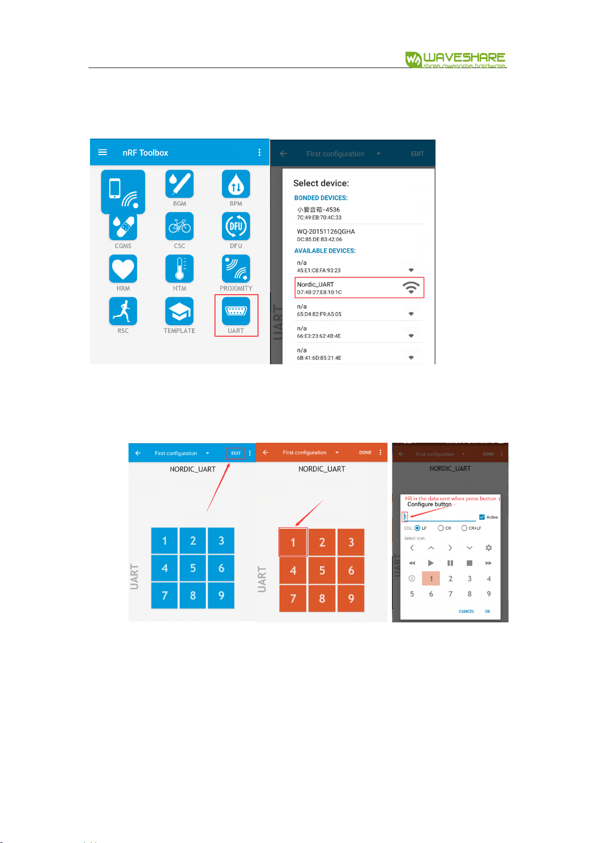
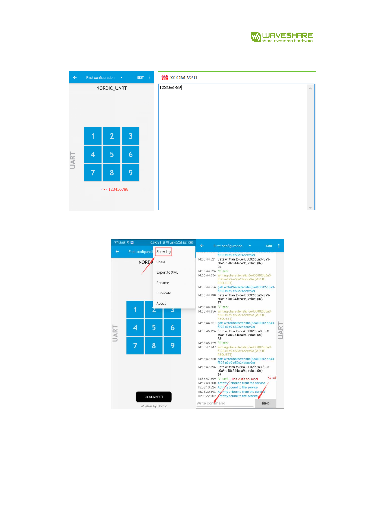
Open nRFToolbox software in your phone and enter UART, Connect Nodic_UART
device
⚫ After connecting, LED1 is on
⚫ You can edit the figures and try to send:
NRF52840 Eval Kit User Manual
Vision: V1.0.1 Date: 2019.01.19 46 / 72
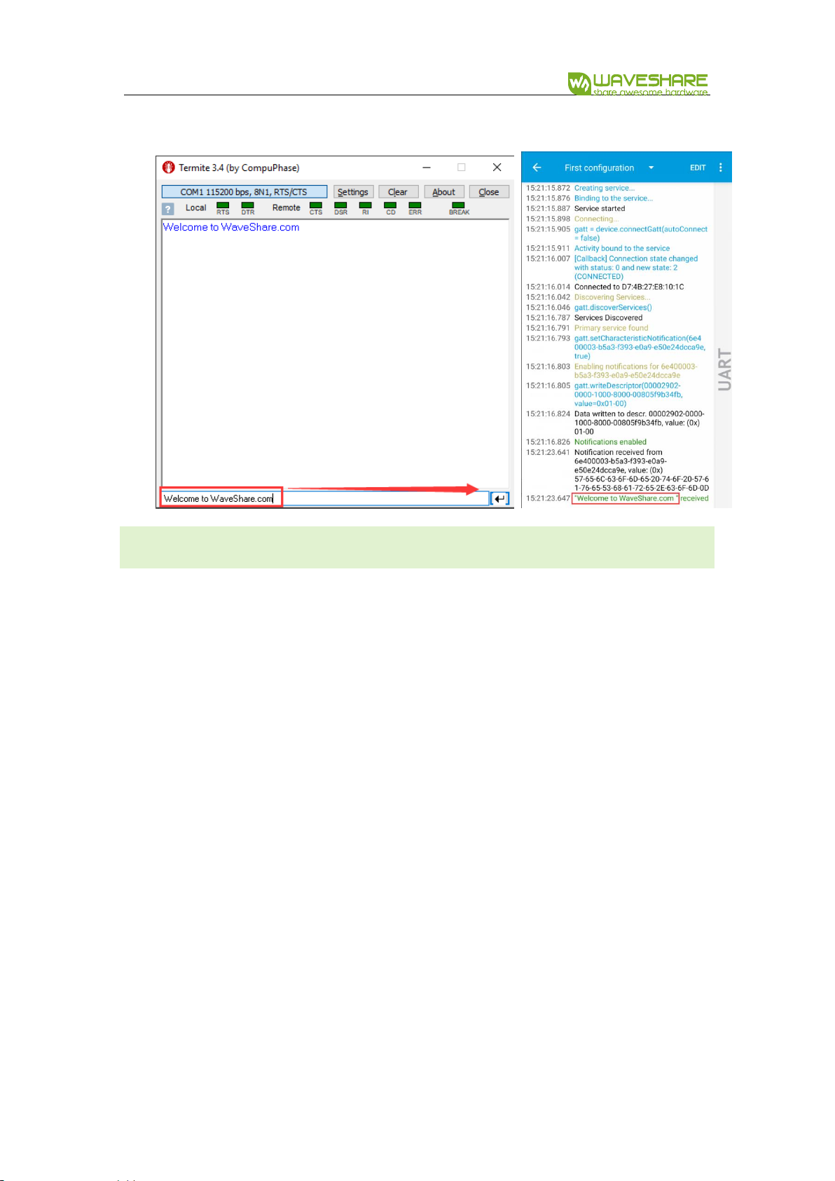
⚫ You can also send data directly on Show log:
NRF52840 Eval Kit User Manual
Vision: V1.0.1 Date: 2019.01.19 47 / 72
BLUETOOTH AGAINST LOS ING
Download:
⚫ Open the project SlaveDevice-Bluetooth-Proximity (APP), which located in Part-2-
Bluetooth-Slave-Device\USER
⚫ Compile and download to eval board
Expected result:
⚫ LED1 is lighted in when broadcasting after downloading
⚫ Turn on Bluetooth service of your phone

NRF52840 Eval Kit User Manual
Vision: V1.0.1 Date: 2019.01.19 48 / 72
⚫ Open nRF Toolbox and clock UART. Connect Nordic_UART device
⚫ After connecting, LED1 will light on. The Toolbox will display as below:

NRF52840 Eval Kit User Manual
Vision: V1.0.1 Date: 2019.01.19 49 / 72
⚫ You can click the indicator button on APP to control P0.15 pin of Eval Kit board.
When testing, you can connect P0.15 to one LED to check the status. Click Delete
button to delete device.
⚫ Press button S1 of Eval Kit board, music will be played in your phone, and
stopped if S1 is pressed again.
⚫ The software also prompt if you take the phone away from the Eval Kit board.
BLUETOOTH BEACON (SUPPORT WECHAT SHAKE)
Beacon is that build a small information base station by using BLE, it can be used in
Indoor navigation, mobile payment, store shopping, Object tracking and so on.
Beacon is not a standard built by Bluetooth SIG
Download:

NRF52840 Eval Kit User Manual
Vision: V1.0.1 Date: 2019.01.19 50 / 72
⚫ Open the project SlaveDevice-Bluetooth-BEACON(WeChat) which located in Part-
2-Bluetooth-Slave-Device\USER
⚫ Compile and Download to Eval Kit Board
【Note】The example is different with official examples(line 74-77)
APP_COMPANY_IDENTIFER change to:0X004c
APP_MAJOR_VALUE change to:0x00,0x0A
APP_MINOR_VALUE change to:0x00,0x07
APP_BEACON_UUID change to:0xFD,0xA5,0x06,0x93,\
0xA4,0xE2,0x4F,0xB1,\
0xAF,0xCF,0xC6,0xEB,\
Expected result:
⚫ Open WeChat, and open Shake, there are not Nearby devices detect
⚫ Download example and run it, LED1 will light on
⚫ Open Shake again, Nearby device is detected

NRF52840 Eval Kit User Manual
Vision: V1.0.1 Date: 2019.01.19 51 / 72
⚫ Click Nearby and try to shake
【Note】The Web page detected is configurable, for more details about it you
can refer to official guide of WeChat: https://zb.weixin.qq.com/intro.xhtml
The testing ID used in the example is the open ID of WeChat
Attributes
Value
UUID
FDA50693-A4E2-4FB1-AFCF-C6EB07647825
Major
10
Minor
7

NRF52840 Eval Kit User Manual
Vision: V1.0.1 Date: 2019.01.19 52 / 72
WIRELESS MOUSE
HOGP profile (HID over GATT Profile) can be used to release wireless mouse function.
HOGP use basic protocol GATT of BLE to release interaction between HID host and
Device.
Download:
⚫ Open the project SlaveDevice_bluetooth-HIDS_MOUSE(APP),
⚫ Compile and download to Eval Kit board.
Expected result:
⚫ Eval Kit board broadcast and LED1 lights on
⚫ Connect P0.11,P0.12,P0.24,P0.25 to buttons
⚫ Cursor will move when press buttons.
Pin
KEY
功能
P0.11
KEY1(left)
Mouse move left for 5 pixels

NRF52840 Eval Kit User Manual
Vision: V1.0.1 Date: 2019.01.19 53 / 72
P0.12
KEY2(up)
Mouse move up for 5 pixels
P0.24
KEY3(right)
Mouse move right for 5 pixels
P0.25
KEY4(down)
Mouse move down for 5 pixels
⚫ If your PC support BLE, you can also used to control cursor on PC
⚫ If you want to use the joystick of Arduino Accessory Shield, you need to modify
the definition of keys in pca10056.h
WIRELESS KEYBOARD
HOGP profile (HID over GATT Profile) can be used to release wireless keyboard
function. HOGP use basic protocol GATT of BLE to release interaction between HID
host and Device.
NRF52840 Eval Kit User Manual
Vision: V1.0.1 Date: 2019.01.19 54 / 72
Download:
⚫ Open the project SlaveDevice_bluetooth-HIDS_KEYBOARD(APP),
⚫ Compile and download to Eval Kit board.
Expected result:
⚫ Eval Kit board broadcast and LED1 is blinking.
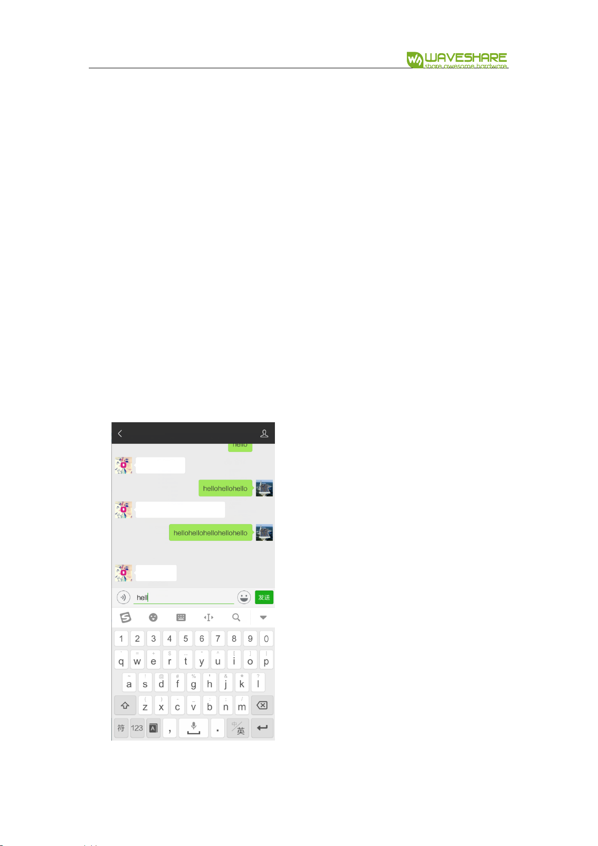
⚫ Open Bluetooth of your Phone, search and connect Nordic_keyboard device. After
connecting, LED1 is on
⚫ Then you can try to input text
Press KEY1 on board to input string “hello”. Connect P0.15 to LED, and you can
find that LED is turned off if Caps Lock is enabled, and the LED is turned on when
Caps Lock is disabled.

NRF52840 Eval Kit User Manual
Vision: V1.0.1 Date: 2019.01.19 55 / 72
CSCS
NRF52840 will send seed, rate, riding distance, total distance and gear ratio data to
phone via BLE.
The data is generated by software (simulated), which is based on Cycling Speed and
Cadence profile.
Download:
⚫ Open the project Bluetooth-CSCS(APP),
⚫ Compile and download to Eval Kit board.
Expected result:
⚫ Eval Kit board is broadcasting and LED1 blinking
⚫ Open nRF Toolbox APP, click CSC(Cycling Speed and Cadence)
⚫ Click Connect to scan and connect to Nordic_CSC device
⚫ After connecting, corresponding data are printed to APP

NRF52840 Eval Kit User Manual
Vision: V1.0.1 Date: 2019.01.19 56 / 72
BLUETOOTH MASTER- CARDIOTACHOMETER
You need two NRF52840 Eval Kit for this example, one is used as master, and another
is slaver.
Download:
⚫ Open project Master-Link-To-Slave-By-HRS(Master), compile and download it to
one Eval Kit board.
⚫ Open project Master-Link-To-Slave-By-HRS(Slaver), compile and download it to
another Eval Kit board.
Both projects can be found in Part-3-Bluetooth-Master-Device\USER
NRF52840 Eval Kit User Manual
Vision: V1.0.1 Date: 2019.01.19 57 / 72
Expected result:
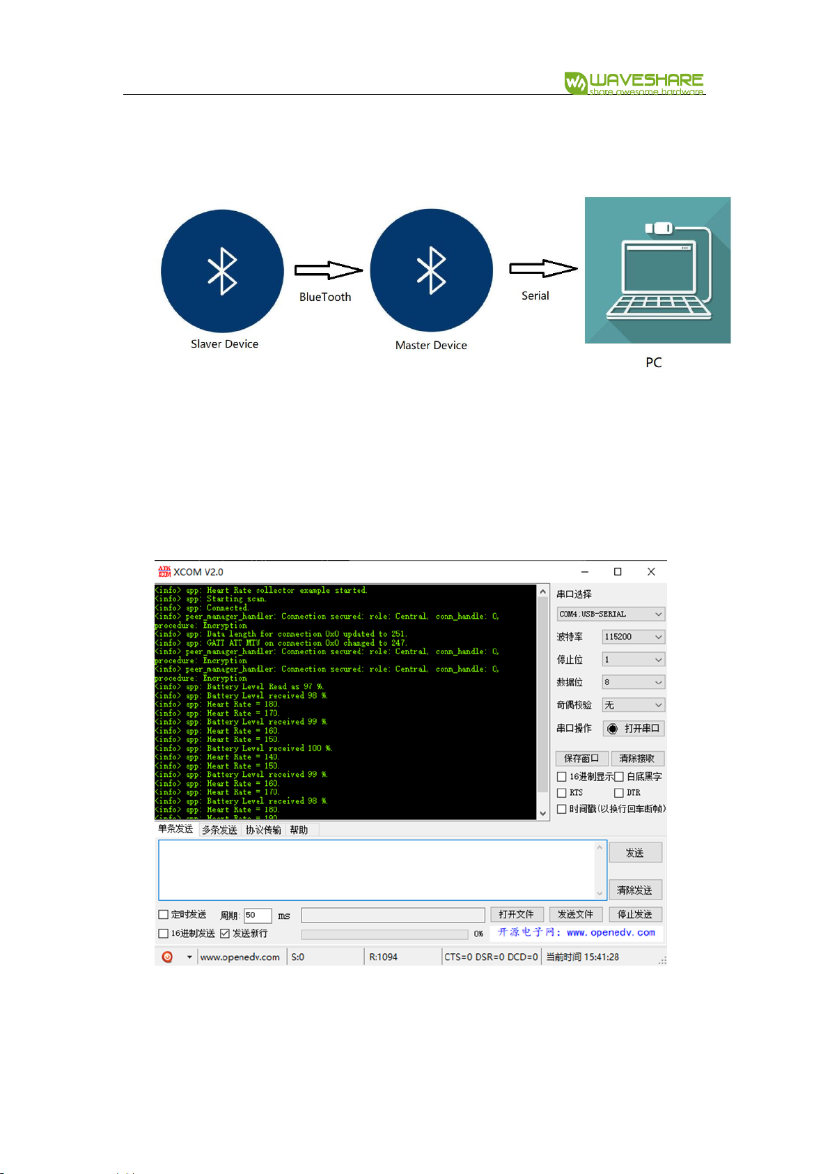
⚫ The communication between two Eval Kit boards is as below:
⚫ After downloading, the master will auto-link to slaver, LED1 are on if they connect
successfully.
⚫ Slaver will send data to Master, which are transferred to serial port and printed in
PC.
NRF52840 Eval Kit User Manual
Vision: V1.0.1 Date: 2019.01.19 58 / 72
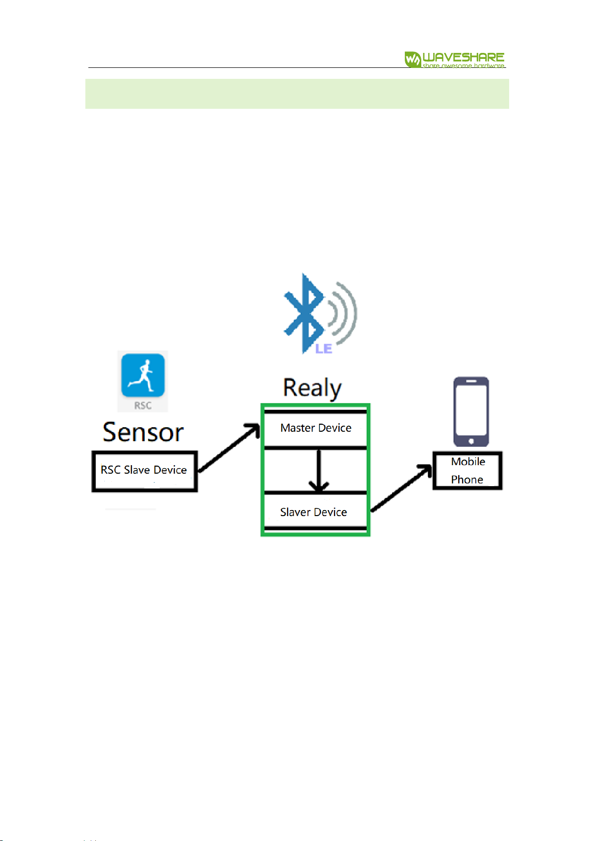
MASTER-SLAVER-BLE RELAY
With this example, Eval Kit board can work as master and slaver at the same time.
⚫ Eval Kit board auto connect to another slaver (RSCS) when work as master
⚫ Eval Kit board will connect to phone when work as slaver
⚫ With BLE Relay example, Eval Kit can receiver data from RSCS slaver and send it to
mobile phone as below:
To complete this example, you require two Eval Kit boards, one is work as Sensor(RSCS
slaver) and another is Relay (Master-Slaver)
Download:
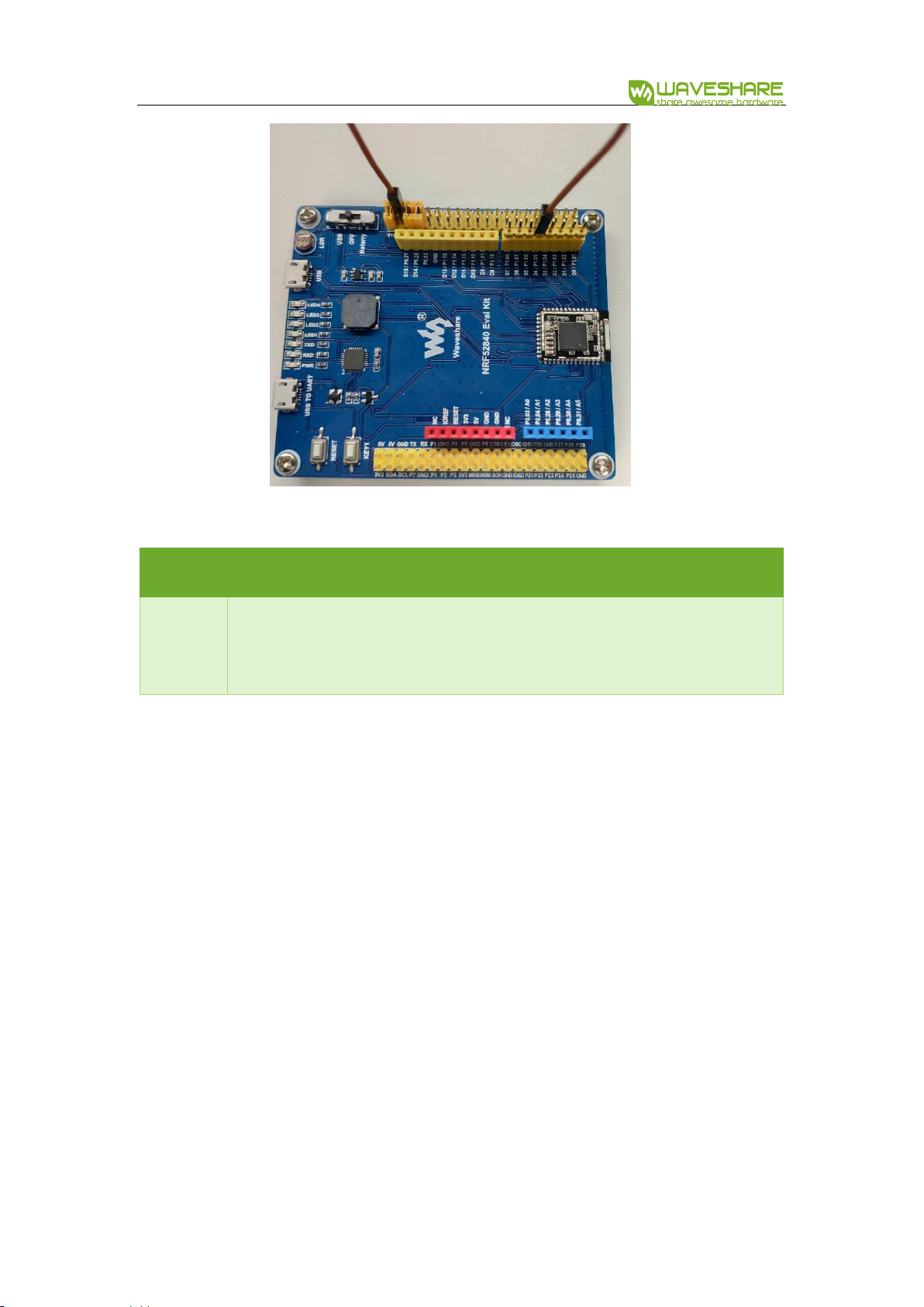
⚫ Open project Master&Slaver-Relay(Master), compile and download to Relay
board.
⚫ Open project Master&Slaver-Relay(Slaver), compile and download to Sensor
board

NRF52840 Eval Kit User Manual
Vision: V1.0.1 Date: 2019.01.19 59 / 72
【Note】 The slaver project is RSC project, it also can be HRM project
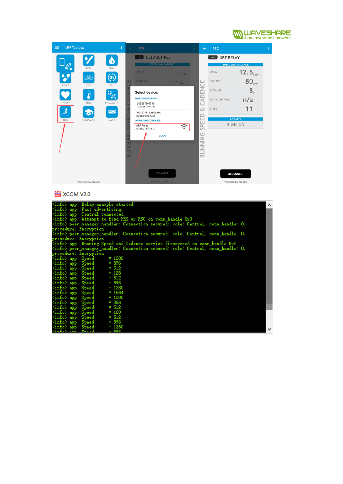
Expected result:
⚫ Power on Relay board, it begins to scan devices(master) and broadcasts(slaver).
LED1 and LED3 are on
⚫ Power on Sensor board, it begin to broadcast and LED1 is blinking, LED1 stay on if
Sensor board connected to Master successfully
Indicators of Relay Board
Indicators
Description
LED1
On: Master is scanning (it keeps scanning even Slaver is connected)
LED2
On: Master has connected to slaver (slaver: sensor board)常
LED3
On: Slaver is broadcasting
LED4
On: Slaver is connected master (master: mobile phone)
【Note】The pin of LED3 is not compatible with SDK, you need to wire it to P1.05
manually.
NRF52840 Eval Kit User Manual
Vision: V1.0.1 Date: 2019.01.19 60 / 72
Indicator of Sensor board:
Indicator
Description
LED1
Blinking: Broadcasting
On: Connected
⚫ Open nRF Toolbox on phone, click RSC and Connect to nRF Relay device.
⚫ After connecting, LED2 of Relay board is turned off and LED4 turns on. Data are
sent to phone.
NRF52840 Eval Kit User Manual
Vision: V1.0.1 Date: 2019.01.19 61 / 72

NRF52840 Eval Kit User Manual
Vision: V1.0.1 Date: 2019.01.19 62 / 72
CHAPTER 10. MESH7
This chapter we describe some of the basic concepts of the Bluetooth Mesh
network using Nordic’s nRF5 SDK for Mesh.
The project we used herein is light-switch example from Nordic’s MESH SDK, for
more details about it, you can refer to official Documents.
The light-switch example demonstrates the major parts of the mesh network
ecosystem. it consists of three minor examples:
⚫ Light switch server: a minimalistic server that implements a generic OnOff server
model, which is used to receive the state data and control the state of LED1 on
the board
⚫ Light Switch Client: A minimalistic client that implements four instances of a
Generic OnOff client model. When a user presses any of the buttons, an OnOff Set
message is sent out to the configured destination address.
⚫ Mesh Provisioner: A simple static provisioner implementation. This provisioner
provisions all the nodes in one mesh network. Additionally, the provisioner also
configures key bindings and publication and subscription settings of mesh model
instances on these nodes to enable them to talk to each other.
These three examples will be referred to as the server, the client and the
provisioner respectively.
The four buttons are used to initiate certain actions and four LEDs are used to
reflect the status of actions as below:
7
You can directly refer to Nordic website:

NRF52840 Eval Kit User Manual
Vision: V1.0.1 Date: 2019.01.19 63 / 72
⚫ Server:
◼ During provisioning process:
◆ LED3 and 4 blinking: Device identification active
◆ LED1 to 4: Blink four times to indicate provisioning process is
completed
◼ After provisioning and configuration is over:
◆ LED1: Reflects the value of OnOff state on the server
⚫ LED ON: Value of the OnOff state is 1 (true)
⚫ LED OFF: Value of the OnOff state is 0 (false).
⚫ Client:
◼ During provisioning process:
◆ LED3 and 4 blinking: Device identification active
◆ LED1 to 4: Blink four times to indicate provisioning process is
completed
◼ After provisioning and configuration is over, buttons on the client are
used to send OnOff Set message to the servers:
◆ Button1: Send a message to the odd group(address: 0xC003) to turn
on LED1
◆ Button2: Send a message to the odd group (address: 0xC003) to turn
off LED1
◆ Button3: Send a message to the even group (address: 0xC002) to
turn on LED1

NRF52840 Eval Kit User Manual
Vision: V1.0.1 Date: 2019.01.19 64 / 72
◆ Button 4: Send a message to the even group (address: 0xC002) to
turn off LED1.
⚫ Provisioner:
◼ Button1: Start provisioning
◼ LED1: Reflects the state of the provisioning.
◆ LED ON: provisioning of the node is in progress
◆ LED OFF: No ongoing provisioning process
◼ LED2: Reflects the state of the configuration
◆ LED ON: Configuration of the node is in process
◆ LED OFF: No ongoing configuration process
The following figure gives the overall view of the mesh network that will be set up
in this example. Numbers in parentheses indicate the addresses that are assigned to
these nodes by the provisioner.
The Mesh is as below:

NRF52840 Eval Kit User Manual
Vision: V1.0.1 Date: 2019.01.19 65 / 72
Hardware requirement:
it required at least three NRF52840 Eval Kit:
⚫ One Eval Kit board for server
⚫ One Eval Kit board for client
⚫ One Eval Kit board for provisioner
Software requirement:
1. nRF Mesh SDK: nrf5_SDK_for_Mesh_v2.2.0_src, download and extract the SDK
2. BLE SDK: nRF5_SDK_15.0.0_a53641a, download and extract the SDK
3. nrfjprog: This tool is used to erase Flash, can be installed by nRFx Command Line
Tools for Windows

NRF52840 Eval Kit User Manual
Vision: V1.0.1 Date: 2019.01.19 66 / 72
4. SEGGER Embedded Studio for ARM 4.10a (The MESH project is built by this tool)
【Note】All the resources should be extracted to the same path, for linked by
compiler. Otherwise, the project is failed to compile.
Download:
⚫ Connect NRF52840 Eval Kit board to PC. Decide which board you want to use as
client and which one as provisioner
⚫ Open projects with SEGGER Embedded Studio for ARM 4.10a
◼ Provisioner:
MESH\nrf5_SDK_for_Mesh_v2.2.0_src\examples\light_switch\provisioner\
light_switch_provisioner_nrf52840_xxAA_s140_6_0_0.emProject
◼ Server:
MESH\nrf5_SDK_for_Mesh_v2.2.0_src\examples\light_switch\proxy_server\ligh
t_switch_proxy_server_nrf52840_xxAA_s140_6_0_0.emProject
◼ Client:
MESH\nrf5_SDK_for_Mesh_v2.2.0_src\examples\light_switch\proxy_client\light
_switch_proxy_client_nrf52840_xxAA_s140_6_0_0.emProject

NRF52840 Eval Kit User Manual
Vision: V1.0.1 Date: 2019.01.19 67 / 72
⚫ Compile projects
⚫ Download projects
⚫ You can also try to debug

NRF52840 Eval Kit User Manual
Vision: V1.0.1 Date: 2019.01.19 68 / 72
Running example:
When the flashing is complete, the script executes a reset operation to start the
example applications.
After the reset, the provisioner waits for user input. Follow these steps to see the
mesh network in actions:
1. Press Button1 on the provisioner board to start the provisioning process
a) The provisioner first provisions and configures the client and assigns the
address 0x100 to the client node
b) The two instances of the OnOff client models are instantiated on
separate secondary elements. For this reason, they get consecutive
addresses starting with 0x101
c) Finally, the provisioner picks up the available devices at random, assigns
them consecutive addresses, and adds them to odd and even groups
d) Observe the LED status on the provisioner, client and server boards.
e) Wait until LED1 on the provisioner board remains ON steadily for a few
seconds, which indicates that all available boards have been provisioned
and configured
f) Press buttons on the client board to change the state of LED1 on the
server boards:
i. Press Button1 on the client board to turn ON LED1 on all servers
with ODD address

NRF52840 Eval Kit User Manual
Vision: V1.0.1 Date: 2019.01.19 69 / 72
ii. Press Button2 on the client board to turn OFF LED1 on all servers
with ODD addresses
iii. Press Button3 on the client board to turn ON LED1 on all servers
with EVEN address
iv. Press Button4 on the client board to turn OFF LED1 on all servers
with EVEN address
g) Press Button1 on the servers to locally change the state of LED1 and
observe that the client receivers the status message from the
corresponding server containing the new state value.
h) You can monitor the RTT logs with J-Link RTT viewer by connecting
provisioner and client.

NRF52840 Eval Kit User Manual
Vision: V1.0.1 Date: 2019.01.19 70 / 72
User Phone as provisioner
Besides the NRF52840 board, you can also use your phone as provisioner.
1. Download client and server project to Eval Kit board respectively.
2. Install nRF Mesh APP to your phone to work as a provisioner.
3. Connect to client and server
4. Configure client and server
5. Press Button1 on client board turns ON LED1 of server
6. Press Button2 on client board turns OFF LED1 of server
Provisioner:
The provisioner configures a network in a fixed, predefined way. it is implemented
as a multi-layered state machine due to the asynchronous nature of the provisioning
and configuration process.
The provisioner first provisions and configures a client device with a known URI
hash. Then configures the servers and networking.

NRF52840 Eval Kit User Manual
Vision: V1.0.1 Date: 2019.01.19 71 / 72
Client:
The light switch client implements a Generic OnOff client. Together with light
switch server and mesh provisioner, it is part of the light switch example network
demonstration, in which it has a provisioner role.
Server:
The light switch server is a Generic OnOff server that has a provisionee role in the
light switch example network demonstration, which is also composed of light switch

NRF52840 Eval Kit User Manual
Vision: V1.0.1 Date: 2019.01.19 72 / 72
client and mesh provisioner. There can be one or more servers in this network, for
example light bulbs.
The provisioner configures this server model instance to communicate with the
client model.
 Loading...