


MCP23017 IO Expansion Board
MCP23017 IO Expansion Board
User Manual
OVERVIEW
This is an I/O expansion module uses I2C interface, gives you 16 GPIO. Supports using
8 expansion modules at the same for up to 128 general purpose pins. Compatible with
3.3V and 5V voltage.
FEATURES
Use two i2c pins, expands up to 16 pins I/O
I2C address is hardware configurable by changing A0/A1/A2
PH2.0 terminal and weld pad, supports parallelly connecting multiple I2C
modules.
Integrates level conversion circuit, compatible with 3.3V and 5V.
Comes with development resources and manual (for
RaspberryPi/micro:bit/Arduino/STM32)
1 / 11

MCP23017 IO Expansion Board
Operating voltage:
5V/3.3V
Interface:
I2C
Interrupt pin:
INTA, INTB
Expansion I/O:
16
Dimension:
38mmx23mm
Holes size:
2.0mm
PIN
Description
Arduino Uno
STM32F407
Raspberry Pi
Vcc
Voltage
3.3V/5V
3.3V/5V
3.3V/5V
GND
Ground
GND
GND
GND
SDA
I2C data line
SDA
PB7
SDA
SCL
I2C clock line
SCL
PB6
SCL
INTA
1
Interrupt pin
3
PA0
0(WiringPi)
INTB
2
Interrupt pin
3
PA0
0(WiringPi)
1
2
SPECIFICATIONS
INTERFACE
You can just connect one interrupt pin when using.
You can just connect one interrupt pin when using.
2 / 11

MCP23017 IO Expansion Board
sudo raspi-config
sudo reboot
HOW TO USE
WORKING WITH RASPBERRY PI
LIBRARIES INSTALLATION
To use the Raspberry Pi demo code, you need to install WiringPi libraries. Please refer
to the page: https://www.waveshare.com/wiki/Libraries_Installation_for_RPi
Download demo code from Waveshare Wiki and extract it to get the demo code.
Copy Raspberry PI folder to your Raspberry Pi. (generally copy to boot of the SD card
which has Raspbian installed)
RUNNING THE CODE
Setting
1. Configuration
2. Choose Interfacing Options -> I2C ->yes to enable I2C interface
3. Save and reboot Raspberry Pi
3 / 11

MCP23017 IO Expansion Board
lsmod
4. After rebooting, you can check if I2C module is enabled by command:
I2C module is enabled normally if you get the information as below,
5. Connecting MCP23017 module to Raspberry Pi according to interfaces
6. You can just connect one of the two interrupt pins to 0(wiringPi) as INTA and INTB
are configured to interconnecting by code
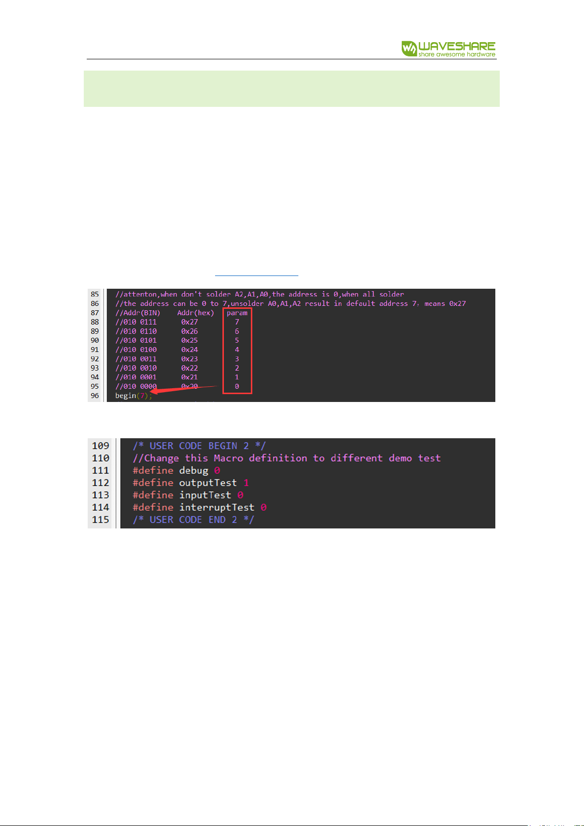
Default address of module is 0x27, you can also change its device address by welding
A2, A0, A1. By default, A2, A1, A0 are all High without welded. If you want to turn them
to Low, you should short these welding points. According to datasheet, slave address
can be configured as below:
4 / 11
MCP23017 IO Expansion Board
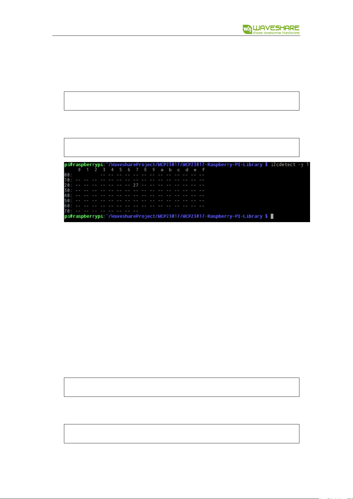
sudo apt-get install i2c-tools
i2cdetect -y 1
cd MCP23017-Raspberry-PI-Library
vim main.c
7. Install i2c-tools for inquiring slave address of i2c modules
8. Inquiring i2c devices connected
If you didn’t change the slave address of MCP23017 module, you will get the
information as above, the slave address is 0x27 inquired as we expected. You can
also change the address by welding A2/A1/A0 points, however, you need to make
sure there are not other modules which have the same address first.
Running
1. Copy the demo code (we have copied to boot) to /home/pi/ directory.
2. Enter the directory of demo code
3. Open main.c file
5 / 11

MCP23017 IO Expansion Board
4. Check the slave address first. If you once changed the address, you should change
the parameter of mcp_begin().
Then, enable macro for corresponding testing.
#define debug: 1: print registers’ value to console
#define outputTest: 1: Output testing
#define inputTest: 1: Input testing
#define interruptTest: 1; Interrupt output testing
【Note】
Output testing: set outputTest to 1; inputTest and interruptTest to 0;
Input testing: set inputTest to 1; outputTest and interruptTest to 0;
Interrupt testing: set interruptTest to 1; outputTest and inputTest to 0
5. After modifying, save and exit.
6 / 11

MCP23017 IO Expansion Board
make
./mymcp23017
3
6. Compiling demo code
7. running the code
EXPECTED RESULT
Output Testing: MCP23017 output High level to 16 I/O for 500ms, and then Low level
for 500ms. You can connect LED to these pins for testing.
Input Testing: Set PA03 of MCP23017 as output and PA1 as input. PA0 will output
level states which is read by PA1. You can connect PA1 to Vcc or GND, and then
connect PA to LED for testing.
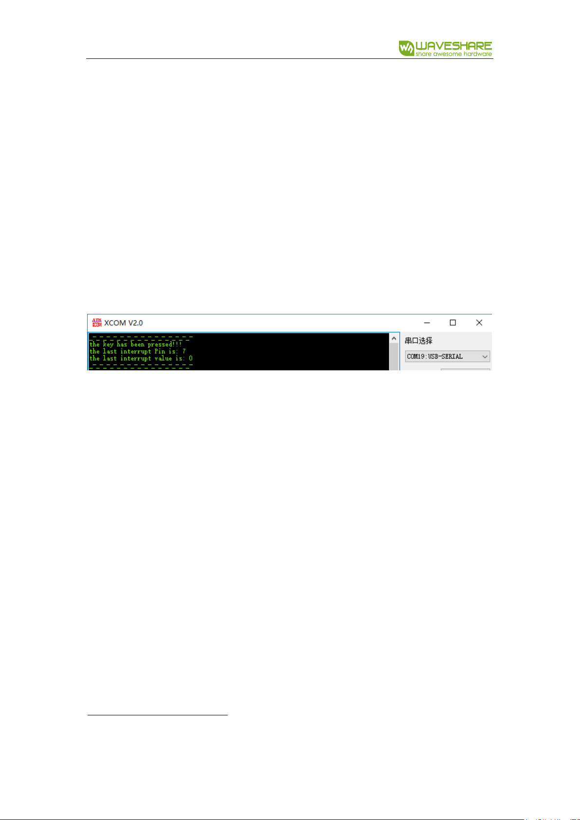
Interrupt Testing: Set PA7 and PB7 pins of MCP23017 as interrupt pins. interrupt
information will be printed to console as below:
PA0~PA7 are printed as 0~7 and PB0~PB7 are printed as 8~15.
7 / 11

MCP23017 IO Expansion Board
WORKING WITH ARDUINO
1. Connect MCP23017 module to Arduino UNO/UNO PLUS according to interfaces
2. Download demo code and extract it. Copy MCP23017-Arduino-Library folder to
libraries directory of IDE.
Output Testing:
1. Open Arduino IDE. Click File->Examples->MCP23017-Arduino-Library->output
2. Configure i2c slave address, default 0x27. You can refer to Running the code about
slave address configuration
3. Compile and upload the code to Arduino board
Expected result: Connect LED to one pin of MCP2317 module, the LED will flicker.
Input Testing:
1. Open Arduino IDE. Click File->Examples->MCP23017-Arduino-Library->input
2. Configure i2c slave address, default 0x27. You can refer to Running the code about
slave address configuration
3. Compile and upload the code to Arduino board
Expected result: Connect PA0 of modules to LED, connect PA1 to Vcc or GND, the LED
will light on/off according to PA1.
8 / 11

MCP23017 IO Expansion Board
Interrupt Testing:
1. Open Arduino IDE. Click File->Examples->MCP23017-Arduino-Library->interrupt
2. Configure i2c slave address, default 0x27. You can refer to Running the code about
slave address configuration
3. Compile and upload the code to Arduino board
Expected result: Open serial monitor, interrupt information will be printed
9 / 11
MCP23017 IO Expansion Board
WORKING WITH STM32
1. Connect MCP23017 module to STM32F407 development board
2. Download demo code form Waveshare Wiki and extract it. Open STM32 project
with software keil5:STM32->MCP23017-STM32F4-Library->MDK-ARM.
Open file main.c to configure i2c slave address. Default address is 0x27. About how to
change it. You can refer to Running the code about slave address configuration
Change macros:
【Note】
Output testing: set outputTest to 1; inputTest and interruptTest to 0;
Input testing: set inputTest to 1; outputTest and interruptTest to 0;
Interrupt testing: set interruptTest to 1; outputTest and inputTest to 0
3. Compile and download demo code to STM32 board.
10 / 11
MCP23017 IO Expansion Board
4
Output Testing: MCP23017 output High level to 16 I/O for 500ms, and then Low level
for 500ms. You can connect LED to these pins for testing.
Input Testing: Set PA04 of MCP23017 as output and PA1 as input. PA0 will output
level states which is read by PA1. You can connect PA1 to Vcc or GND, and then
connect PA to LED for testing.
Interrupt Testing: Set PA7 and PB7 pins of MCP23017 as interrupt pins. interrupt
information will be printed to serial as below:
PA0~PA7 are printed as 0~7 and PB0~PB7 are printed as 8~15.
11 / 11
 Loading...