

Page 1

W
W
aves Y56K User Manual
aves Y56K User Manual
Page 2

Page 3

3
3
Y56K User Guide
Contents
Warranty..............................................................................8
Warranty Service___________________________________________________________8
Trademarks _______________________________________________________________9
Copyright ________________________________________________________________9
Waves Contact Information __________________________________________________9
Introduction......................................................................10
Packing List ______________________________________________________________10
Chapter 1...........................................Before you begin....11
AW Operating System Requirements__________________________________________11
OPTION Slot 1 or Slot 2 ____________________________________________________11
OPTION slot 1 _____________________________________________________________________11
OPTION slot 2 _____________________________________________________________________11
Installing the Y56K ________________________________________________________11
Important Notes __________________________________________________________12
Accessing the Y56K for the first time ____________________________________________________12
DSP management ___________________________________________________________________12
Operating System ___________________________________________________________________12
Power-on after installation ____________________________________________________________12
Chapter 2......................................Y56K User Interface....13
Viewing the Y56K Interface _________________________________________________13
Y56K main page (Y56K Main) _______________________________________________13
Y56K Main menu bar ________________________________________________________________14
Effect chain column _________________________________________________________________14
SRC – Source column ________________________________________________________________14
GRP – pair grouping_________________________________________________________________14
Effect chains _______________________________________________________________________14
Load/Save dialog boxes _____________________________________________________14
Load dialog box_____________________________________________________________________14
Loading a preset __________________________________________________________________15
Cancel__________________________________________________________________________15
Factory Presets browser ____________________________________________________________15
Page Scroll Bar ___________________________________________________________________15
User Presets browser_______________________________________________________________15
Save dialog box _____________________________________________________________________15
Exit ____________________________________________________________________________15
Preset browser ___________________________________________________________________15
Page Scroll Bar ___________________________________________________________________16
Text Palette______________________________________________________________________16
Cancel__________________________________________________________________________16
Delete __________________________________________________________________________16
Save ___________________________________________________________________________16
Text Input box ___________________________________________________________________16
Basic operation of the Y56K _________________________________________________16
Page 4

Accessing Y56K pages ________________________________________________________________16
Navigating the Y56K’s pages ___________________________________________________________17
Y56K User Interface Functions_________________________________________________________17
Cursor – Using the cursor keys _______________________________________________________17
Pointer – Using the mouse __________________________________________________________17
Buttons _________________________________________________________________________17
Faders/numerical boxes ____________________________________________________________17
Popup menus ____________________________________________________________________17
Graphs _________________________________________________________________________18
VU meters ______________________________________________________________________18
Peak and Clip Indicators ___________________________________________________________18
Chapter 3.........................Patching audio to the Y56K....19
General _________________________________________________________________19
Using an effect chain as a mono channel insert__________________________________19
Using an effect chain as a stereo channel insert _________________________________20
Using an effect chain as an auxiliary send/return ________________________________21
Using the Y56K’s lightpipe I/O_______________________________________________24
Patching lightpipe input ______________________________________________________________24
Synching ADAT to the AW __________________________________________________________25
Patching the audio signal to an AW channel ____________________________________________25
Patching lightpipe output_____________________________________________________________25
Chapter 4....................................................Y56K pages....26
Y56K Main page __________________________________________________________26
Special page________________________________________________________________________26
Y56K Main Preset name ______________________________________________________________26
Y56K Main Load and Save ____________________________________________________________26
Y56K Main Load button ___________________________________________________________26
Y56K Main Save__________________________________________________________________27
Effect block ________________________________________________________________________27
Clicking on an empty Effect Block ____________________________________________________27
Effect list ___________________________________________________________________________27
Paste_______________________________________________________________________________28
Clicking on an effect block containing an effect __________________________________________28
Properties ___________________________________________________________________________28
Bypass/Enable _______________________________________________________________________28
Delete______________________________________________________________________________28
Copy ______________________________________________________________________________28
Cut________________________________________________________________________________28
Paste_______________________________________________________________________________28
About page _____________________________________________________________ 29
Effect chain popup menu _____________________________________________________________29
Bypass__________________________________________________________________________29
Clear___________________________________________________________________________29
Copy ___________________________________________________________________________29
Cut ____________________________________________________________________________29
Paste ___________________________________________________________________________29
SRC - Source Selection _______________________________________________________________30
Console_________________________________________________________________________30
Y56K User Guide
4
Page 5

ADAT __________________________________________________________________________30
Group selection_____________________________________________________________________30
Mono __________________________________________________________________________30
Stereo __________________________________________________________________________30
Switching between mono and stereo __________________________________________________31
Switching a mono effect chain to stereo ____________________________________________________31
Switching a stereo effect chain to mono ____________________________________________________31
Special page ______________________________________________________________32
DSP system usage ___________________________________________________________________32
Chain Delay________________________________________________________________________32
Update Mode_______________________________________________________________________32
Chapter 5..................................................Y56K effects....33
General _________________________________________________________________33
WaveSystem________________________________________________________________________33
Bypass__________________________________________________________________________33
Setup A, Setup B, [A→B]___________________________________________________________33
Load and Save ___________________________________________________________________33
Load_______________________________________________________________________________33
Save _______________________________________________________________________________33
Chain navigation arrows [ ]_____________________________________________________33
Waves logo ___________________________________________________________33
Info Line __________________________________________________________________________34
L1-Limiter / L1-UltraMaximizer _____________________________________________35
Introduction _______________________________________________________________________35
L1 component plug-ins_______________________________________________________________36
Important Digital Audio Facts for Optimal L1 Use _________________________________________36
Maximum Level __________________________________________________________________36
Maximum Resolution and IDR™ ____________________________________________________36
Using the L1 _______________________________________________________________________37
The Peak Limiter _________________________________________________________________37
Release Time and Attenuation Meters _________________________________________________37
The IDR Section __________________________________________________________________38
Quantize ___________________________________________________________________________38
Dither _____________________________________________________________________________39
Noise Shaping____________________________________________________________________39
Digital/Analog Domain ____________________________________________________________40
16-bit (and higher) Mastering _________________________________________________________40
Recommended Settings ____________________________________________________________40
RCL - Renaissance Compressor ______________________________________________41
Release Mode_______________________________________________________________________41
ARC ™ (Auto Release Control) ______________________________________________________42
Compression Behavior _______________________________________________________________42
Character__________________________________________________________________________42
Threshold _________________________________________________________________________43
Ratio _____________________________________________________________________________43
Attenuation ________________________________________________________________________44
Compressor Attack __________________________________________________________________44
Compressor Release _________________________________________________________________44
Gain______________________________________________________________________________45
Y56K User Guide
5
Page 6

Limiter Section _____________________________________________________________________45
REQ - Renaissance Equalizer ________________________________________________46
Filter Descriptions __________________________________________________________________46
Resonant Shelf Filters______________________________________________________________46
Cut filters _______________________________________________________________________46
Parametric (Bell) Filters____________________________________________________________47
The Controls _______________________________________________________________________47
Individual band controls ___________________________________________________________47
Gain_______________________________________________________________________________47
Freq _______________________________________________________________________________47
Q shape ____________________________________________________________________________48
In-out / Filter Type____________________________________________________________________48
Trim ___________________________________________________________________________48
DSR - DeEsser ____________________________________________________________50
Quick Start ________________________________________________________________________50
DeEsser Controls ___________________________________________________________________51
Threshold and Energy Detector ______________________________________________________51
Attenuation _____________________________________________________________________51
Output _________________________________________________________________________52
Audio __________________________________________________________________________52
Frequency _______________________________________________________________________52
Sidechain _______________________________________________________________________52
Monitor ________________________________________________________________________52
TV - TrueVerb ____________________________________________________________53
Quick Start ________________________________________________________________________53
TrueVerb Interface __________________________________________________________________54
Time Response graph ______________________________________________________________54
Time Response controls ____________________________________________________________54
Dimension __________________________________________________________________________54
Room Size __________________________________________________________________________54
Distance ____________________________________________________________________________54
Link _________________________________________________________________________55
Balance ____________________________________________________________________________55
R.Time_____________________________________________________________________________55
PreDelay ___________________________________________________________________________55
Frequency Response graph __________________________________________________________55
Frequency Response controls ________________________________________________________56
RevShelf ____________________________________________________________________________56
ERAbsorb ___________________________________________________________________________56
Freq _______________________________________________________________________________56
Reverb damping (Rev HF, Rev LF)________________________________________________________56
ER-HP _____________________________________________________________________________56
Input/Output Section______________________________________________________________57
Input ______________________________________________________________________________57
Output _____________________________________________________________________________57
Using TrueVerb _____________________________________________________________________57
Thru mode ______________________________________________________________________57
Adjusting Thru mode ______________________________________________________________58
Constant perceived level ________________________________________________________________58
Reverb Linked to Early Reflections ________________________________________________________58
Y56K User Guide
6
Page 7

Distance, Balance, RoomSize, R.Time _____________________________________________________58
Send mode ______________________________________________________________________58
Adjusting Send mode ______________________________________________________________58
ST – SuperTap Delay _______________________________________________________59
Normal and Multi-tap Delays__________________________________________________________59
SuperTap Controls __________________________________________________________________59
Pan Graph ______________________________________________________________________59
Tap Delay Grid ___________________________________________________________________60
Modulator ______________________________________________________________________61
Output _________________________________________________________________________61
Tap controls _____________________________________________________________________61
Direct______________________________________________________________________________61
Delay lines (taps) _____________________________________________________________________62
Tap marker _________________________________________________________________________62
EQ/Filter section__________________________________________________________________62
In/Out _____________________________________________________________________________62
Freq _______________________________________________________________________________62
Feedback section__________________________________________________________________62
Mode ______________________________________________________________________________63
Gain_______________________________________________________________________________63
Rotate _____________________________________________________________________________63
Feedback EQ/filter ____________________________________________________________________63
Chapter 6..............................Using scene automation....64
Chapter 7......................................Updating the Y56K....65
Y56K User Guide
7
Page 8

Warranty
KS.Waves Ltd. (“Waves”) warrants that the hardware contained herein shall conform in all material respects
to the specifications contained in the product documentation for a period of one (1) year from the date of
original purchase from Waves or its authorized resellers. In the case of a valid warranty claim, your sole and
exclusive remedy and Waves’ entire liability under any theory of liability will be, at Waves’ sole discretion, to
repair or replace the Product without charge or to refund the purchase price to you.
THIS WARRANTY IS IN LIEU OF ALL WARRANTIES, WHETHER ORAL OR WRITTEN, EXPRESS,
IMPLIED OR STATUTORY, WAVES MAKES NO OTHER WARRANTY, EITHER EXPRESS OR IMPLIED,
INCLUDING, WITHOUT LIMITATION, ANY IMPLIED WARRANTIES OF MERCHANTABILITY, FITNESS FOR A PARTICULAR PURPOSE, OR NON-INFRINGEMENT, PURCHASER’S SOLE AND EXCLUSIVE REMEDY UNDER THIS WARRANTY SHALL BE REPAIR OR REPLACEMENT AS SPECIFIED
HEREIN.
This limited warranty, with all terms, conditions and disclaimers set forth herein, shall extend to the original purchaser and anyone who purchases the Product within the specified warranty period. Waves does not
authorize any third party, including any dealer or sales representative, to assume any liability or make any
additional warranties or representation regarding this Product on behalf of Waves.
IN NO EVENT WILL WAVES BE LIABLE FOR ANY DIRECT, INDIRECT, SPECIAL, INCIDENTAL OR
CONSEQUENTIAL DAMAGES RESULTING FROM ANY DEFECT IN THE PRODUCT, INCLUDING
LOST PROFITS, DAMAGE TO PROPERTY AND, TO THE EXTENT PERMITTED BY LAW, DAMAGE
FOR PERSONAL INJURY, EVEN IF WAVES HAS BEEN ADVISED OF THE POSSIBILITY OF SUCH
DAMAGES.
Some states do not allow the exclusion of implied warranties or limitations on the duration of an implied
warranty, so the above limitations may not apply to you. This warrant gives you specific legal rights. You
may have other rights, which vary, by state to state.
This agreement will be governed by the laws of Israel. In the event of a dispute arising under this
Agreement, you consent to jurisdiction in the State of Israel.
Warranty Service
For warranty service, please call one of Waves’ offices listed on the back of this document so as to obtain a
Return Authorization (RA) number. The Product, with RA number written outside the shipping box in
bold letters, must be sent, transportation and insurance charges prepaid, to a Waves location (U.S. customers to TN office; all other locations to Tel Aviv, Israel). Your name, address, telephone number, copy of
original sales invoice and detailed description of the problem must accompany the Product. Waves will not
accept responsibility for loss or damage in transit. The Warranty is void if the Product serial numbers have
been removed from the Product or if the Product has been misused, modified, disassembled or repaired
Y56K User Guide
8
Page 9

without authorization, as determined in Waves’ discretion. For warranty service, in case you purchased the
product from an authorized dealer then please call your Waves’ dealer so as to obtain a Return
Authorization (RA) number. The Product, with RA number written outside the shipping box in bold letters,
must be sent, transportation and insurance charges prepaid, to your Waves’ Dealer.
In any other case please call one of Waves’ offices listed on the back of this document so as to obtain a
Return Authorization (RA) number. The Product, with RA number written outside the shipping box in
bold letters, must be sent, transportation and insurance charges prepaid, to a Waves location (U.S. customers to TN office; all other locations to Tel Aviv, Israel).
In all cases your name, address, telephone number, copy of original sales invoice and detailed description of
the problem must accompany the Product. Waves will not accept responsibility for loss or damage in transit. The Warranty is void if the Product serial numbers have been removed from the Product or if the
Product has been misused, modified, disassembled or repaired without authorization, as determined at
Waves’ discretion.
Trademarks
ADAT is a registered trademark of Alesis Corporation. Yamaha is a trademark of Yamaha Corporation. All
other trademarks are the property of their respective holders and are hereby acknowledged.
Copyright
No part of the Y56K software or the manual may be reproduced or distributed in any form or by any means
without the prior written authorization of Waves Ltd.
Waves Contact Information
Our web site may have information for this product, including updates and new options, as well as information on how to contact us, etc. Just surf to www.waves.com.
North and South America:
Waves
306 West Depot Ave.
Suite 100
Knoxville, TN 37917
tel: 1-865-546-6115
fax: 1-865-546-8445
Rest of the world:
Waves (KS Waves, Ltd.)
Azrieli Center
The Round Tower, 21st Floor
132 Derech Petach-Tikva
Tel-Aviv, Israel
tel: 972-3-6081648
fax: 972-3-6081656
Y56K User Guide
9
Page 10

Introduction
Thank you for purchasing the Waves Y56K processor card. This guide contains important information
about how to install and use the card on the AW4416 and other supported digital consoles and workstations
by Yamaha Corp.
Note! For convenience and generality, this user guide uses the term AW to indicate the AW4416 and other
supported Professional Audio Workstations and digital mixers.
Packing List
The Y56K package should contains the following:
Y56K mini-YGDAI option card
User Guide (this document)
Registration Card
Quick Start Card
If any items are missing, please contact your dealer.
Y56K User Guide
10
Page 11

Chapter 1: Before you begin
This chapter prepares your system to use the Y56K card with your AW.
AW Operating System Requirements
The Y56K will operate only with a suitable AW firmware version. If your firmware version does not support
the Y56K, contact your local Yamaha dealer.
OPTION Slot 1 or Slot 2
The Y56K operates in either of the AW’s OPTION I/O slots with the following differences:
OPTION slot 1
A card installed in OPTION slot 1 accesses its screens/pages by pressing [Aux7]→[F5]. Once installed, the
Y56K’s effect chains are identified by the AW as the slot number (SL1) and the chain number.
Routing audio signals to and from the card’s effect chains is done through:
SL1-1 = effect chain 1
SL1-2 = effect chain 2
SL1-3 = effect chain 3
SL1-4 = effect chain 4
SL1-5 = effect chain 5
SL1-6 = effect chain 6
SL1-7 = effect chain 7
SL1-8 = effect chain 8
OPTION slot 2
A card installed in OPTION slot 2 accesses its screens/pages by pressing [Aux8]→[F5]. Once installed, the
Y56K’s effect chains are identified by the AW as the slot number (SL2) and the chain number.
Routing audio signals to and from the card’s effect chains is done through:
SL2-1 = effect chain 1
SL2-2 = effect chain 2
SL2-3 = effect chain 3
SL2-4 = effect chain 4
SL2-5 = effect chain 5
SL2-6 = effect chain 6
SL2-7 = effect chain 7
SL2-8 = effect chain 8
Installing the Y56K
The Y56K card is installed into either of the mini-YGDAI OPTION I/O slots (1 or 2) on the rear panel of
the AW.
Y56K User Guide
11
Page 12

1. Make sure that the AW power is switched off. For additional safety, disconnect the power cable from the
AC socket.
2. From the OPTION I/O slot on the rear panel of the AW, remove the two screws that hold the cover in
place.
3. Slide the Y56K card along the rail inside the slot until it clicks into place.
4. Tighten the two screws back to fasten the card securely.
Refer to the AW Operation Guide for further instructions on installing option cards.
Important Notes
Accessing the Y56K for the first time
To access your Y56K first select [AUX7]->[F5] (for a Y56K installed in option slot 1) or [AUX8]->[F5] (for
a Y56K installed in option slot 2).
This will bring up the Y56K splash screen the first time the unit is accessed. Click anywhere on the screen
with the mouse or press the [ENTER] key to close the splash screen and display Y56K Main page.
NNotote!
e! It might take a few seconds for the Y56K to initialize itself and display its Main page.
NNotote!
e! Using AUX7 and AUX8 to access your Y56K does NOT disable the internal AW effects - the use of
AUX7 and AUX8 is only for the location of the control interface to the Y56K .
DSP management
The Y56K employs two DSPs: One DSP services effect chains 1-4, the other effect chains 5-8. Even if effect
chains 1-4 are fully loaded, effects can still be loaded to chains 5-8. The current amount of DSP resources
used on each DSP chip can be viewed on the “Special” page.
Operating System
This manual refers to routing between the AW4416 and the Y56K. If the Y56K is installed on different systems, refer to their operation guides to interface with the Y56K.
Power-on after installation
If the Y56K has been installed correctly, a “PLUG-IN CARD is initializing...” progress message will be displayed when powering the AW.
Y56K User Guide
12
Page 13
Chapter 2: Y56K User Interface
This chapter explains the Y56K’s user interface but assumes operational knowledge of the AW. Refer to the
AW’s Operation Guide to learn its functions.
Viewing The Y56K Interface
To view the Y56K interface:
Select [AUX7]->[F5] (for a Y56K installed in option slot 1)
Or
Select [AUX8]->[F5] (for a Y56K installed in option slot 2).
This will bring up the Y56K splash screen the first time the unit is accessed. Click anywhere on the screen
with the mouse or press the [ENTER] key to close the splash screen and display Y56K Main page.
Note! It might take a few seconds for the Y56K to initialize itself and display its Main page.
Note! Using AUX7 and AUX8 to access your Y56K does NOT disable the internal AW effects - the use of
AUX7 and AUX8 is only for the location of the control interface to the Y56K .
Y56K main page (Y56K Main)
When accessing the Y56K for the first time after system boot, the “Y56K Main” page is displayed (below). In
this central program page, you can:
load effects to effect chains;
select the input source to the chains;
group the chains to stereo pairs;
save and restore settings.
All other Y56K pages are accessed through this page.
Y56K User Guide
13
Page 14

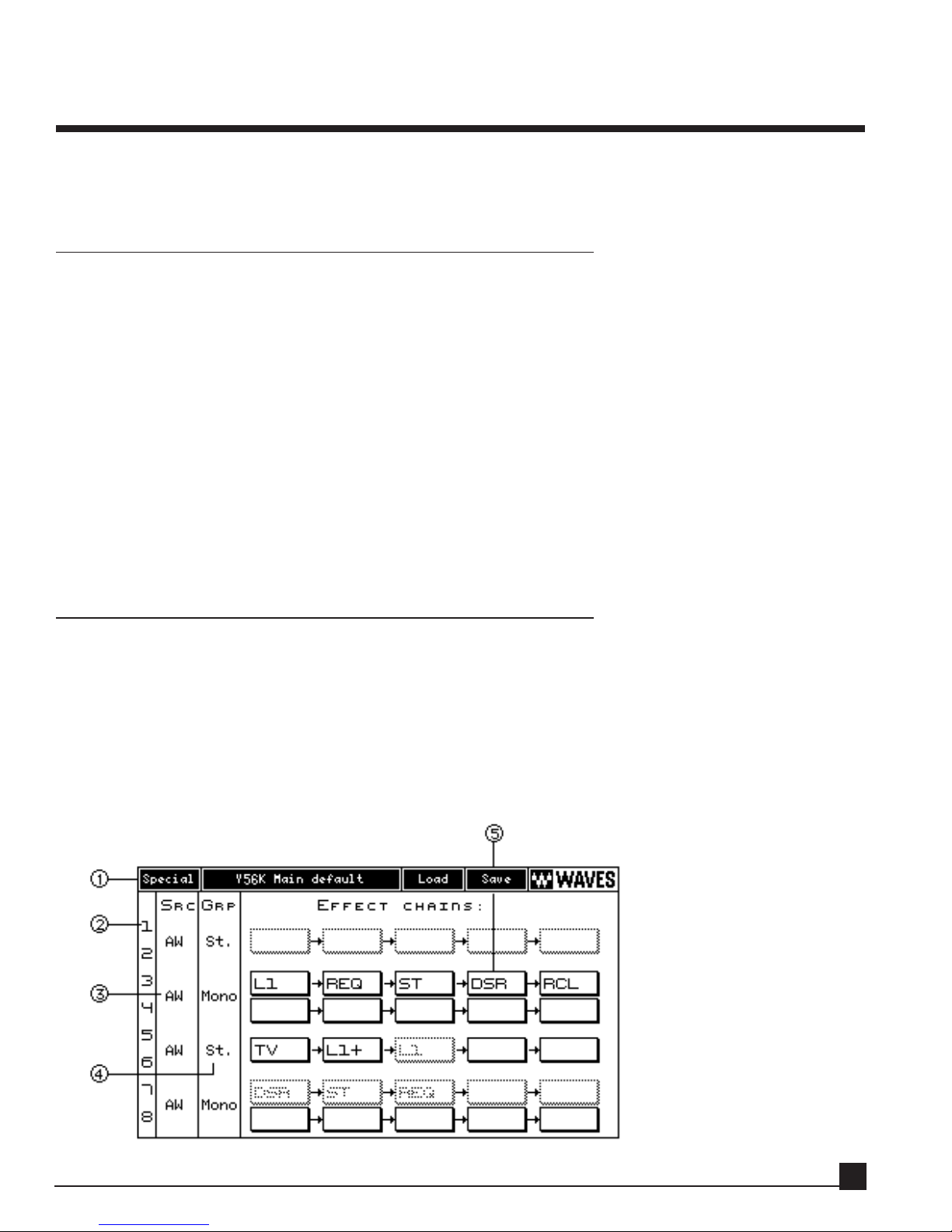
1. Y56K Main menu bar
The Y56K Main menu bar contains buttons to access pages that relate to the status of the card (Load, Save,
Special, About). Functions specific to each effect are accessed through that effect’s Properties page (see
chapter 5).
2. Effect chain column
This column lists the effect chains. The Y56K card has eight effect chains (1-8). Click an effect chain number in this column to open the Effect Chain popup menu.
3. SRC – Source column
This column displays and allows selection of the Y56K’s main audio input source from the AW or ADAT. It
is possible to switch the input source between ADAT and AW for each chain pair (1/2, 3/4, 5/6, 7/8) independently.
4. GRP – pair grouping
This column displays and allows stereo grouping (pairing) of channels 1/2, 3/4, 5/6, and 7/8. Selecting
mono or stereo does not affect the AW and Y56K routing schemes but does affect whether a mono or stereo
effect can be inserted in the chain.
Switching an effect chain (with effects) from mono to stereo, or vice versa, replaces the inserted effects with
their mono or stereo counterparts when applicable or clears the chain.
Refer to the “Switching between mono and stereo” section in the “Y56K pages” chapter for more information.
5. Effect chains
This section displays the Y56K’s eight effect chains with five effect blocks each.
Load/Save dialog boxes
This section discusses the dialogs used when saving or loading presets.
Load dialog box
The Load dialog box (below) opens when loading either a Y56K Main preset or an effect preset.
Y56K User Guide
14
Page 15
Loading a preset
Scroll to the Preset to load using the [ ]/[ ] CURSOR keys or [DATA/JOG] dial, and press the
[ENTER] key to load the preset. Alternately, double-click the mouse on the selected preset.
1. Cancel
Click Cancel to close the Load dialog window without loading and return to the previous page.
2. Factory Presets browser
The preset browser is divided to factory-set and user-made preset sections.
This section lists factory presets.
3. Page Scroll Bar
If the number of presets exceeds one page, click the Page Scroll Bar to display additional pages.
4. User Presets br
owser
The preset browser is divided to factory-set and user-made preset sections.
This section lists user presets. If the number of saved presets exceeds one page, access additional
pages by continuing to scroll, use the left/right CURSOR keys, or click the Page Scroll Bar.
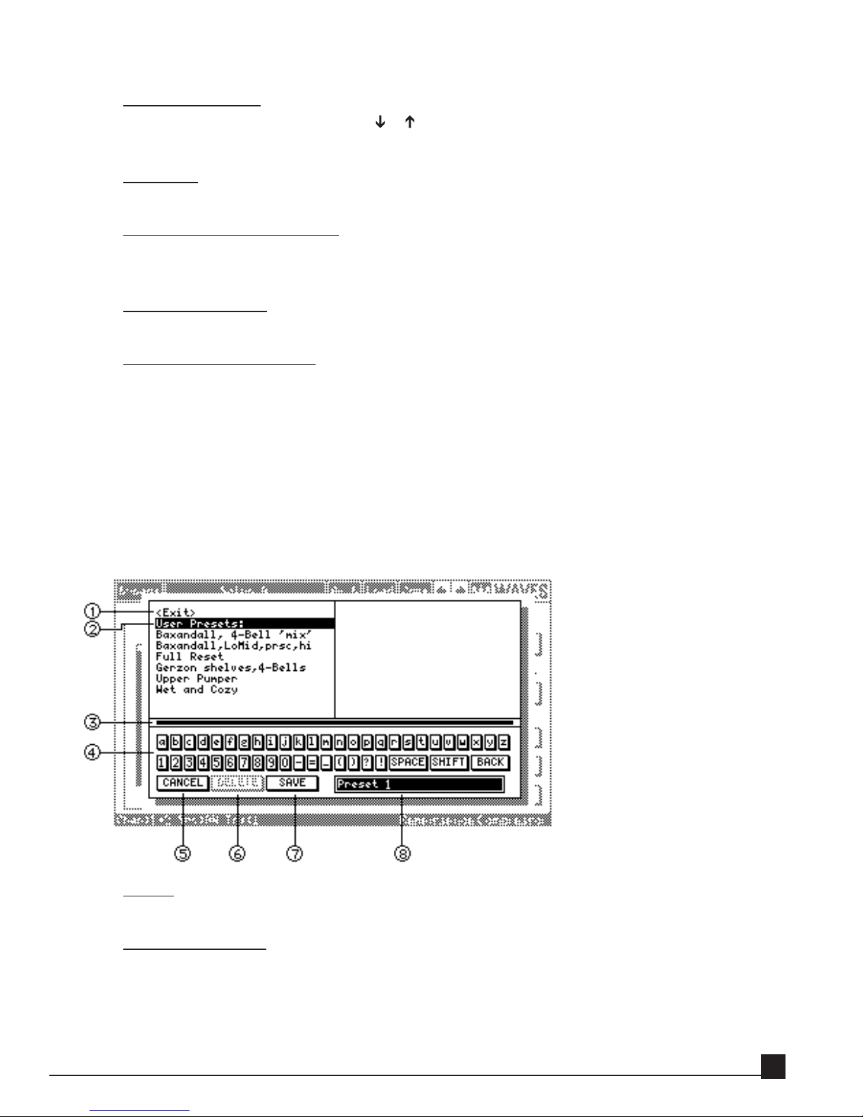
Save dialog box
The Save dialog box (below) opens when saving either a Y56K Main preset or an effect preset.
This dialog box allows you to save or delete a user-made preset (factory-set presets cannot be deleted).
Saving or deleting a preset applies only to the preset that is currently highlighted in the Text Input box (see
item 8 below).
1. Exit
Select Exit to move the CURSOR to the Text Palette area.
2. Preset browser
The Preset browser lists all user presets. Factory presets are not displayed because they cannot be
overwritten.
To use an existing preset name as a starting point for the new preset name, or to replace an existing
preset:
Y56K User Guide
15
Page 16

rotate the [DATA/JOG] dial or;
use the [ ]/[ ]/[ ]/[ ] CURSOR keys or;
click on the preset name.
Press the [ENTER] key or click to highlight the preset name in the Text Input box for editing. A
highlighted preset name in the Text Input box can be overwritten or deleted.
3. Page Scroll Bar
If the number of presets exceeds one page, click the Page Scroll Bar to scroll between pages.
4. T
ext Palette
Select the character to input in the Text Input box. Use [Shift] to switch between lower and upper
case characters, and [BACK] to backspace.
Use the [DATA/JOG] dial or CURSOR keys to scroll through the text characters. Click the [ENTER]
key to enter the character into the Text Input box. Alternately, click the character to enter it into the
Text Input box.
There are two ways to move between the Text Palette area and the Preset Browser section:
Use to mouse to click directly in the desired area.
Use the CURSOR and [ENTER] keys – In the Preset Browser, press the [ENTER] key on a preset
name to highlight it in the Text Input box and move the CURSOR to the Text palette area. In the
Text palette area, press the [ ] arrow key to move the CURSOR up to the Preset Browser section.
5. Cancel
Click Cancel to exit this window without saving.
6. Delete
Click Delete to delete the preset selected in the Text Input box.
Scroll to the preset to delete and click its name to highlight it. Press the [ENTER] key or click a second time to highlight the preset in the Text Input box, and press Delete.
7. Save
Click Save to save the preset and exit the Save dialog. Saving a preset under the same name as an
existing preset displays a confirmation to replace the old preset with the new one.
8. Text Input box
Characters, numerals, and symbols can be input in the Text Input box. A preset can be saved or
deleted only when its name is highlighted in the Text Input box.
Basic operation of the Y56K
Accessing Y56K pages
If the Y56K is installed in slot 1, press the [Aux7] key → [F5] (Plug in 1) key to access the Y56K’s pages. If
the Y56K is installed in slot 2, press the [Aux8] key → [F5] (Plug in 2) key. After exiting and re-entering the
Y56K in the same work session, the last page from the previous session is displayed.
NNotote!
e! The first time you access the card after the AW has been turned on, the card takes a few seconds to
Y56K User Guide
16
Page 17

initialize, load, and display its About splash screen. Click on the screen or press [ENTER] to display the
Y56K Main page.
Navigating the Y56K’s pages
Navigate within the Y56K’s pages by moving the CURSOR or POINTER to the on-screen item. If the onscreen item is a button supporting a popup menu, it will open when clicking the [ENTER] key or mouse
button.
Access an effect Properties page or other pages through the Y56K Main page either by clicking a button or
selecting the item from a popup menu.
Y56K User Interface Functions
This section describes the Y56K’s user interface functions.
In general, all user operations are done either by using the AW’s CURSOR and [ENTER] keys, and the
[DATA/JOG] dial, or by using the AW’s serial mouse.
Cursor – Using the cursor keys
Similar the to AW interface, the blinking rectangular frame in the display is called the CURSOR.
When the CURSOR outlines an on-screen item, it is selected for operation.
Use the AW’s [ ]/[ ]/[ ]/[ ] CURSOR keys to move through the on-screen items.
Refer to the AW Operation Guide for instructions on using the CURSOR.
Pointer – Using the mouse
Connecting a serial mouse to the MOUSE connector on the AW rear panel results in similar functions within the Y56K interface.
Use the mouse to select and edit on-screen items, click buttons, open popup menus and select menu
items, and operate directly on some of the effect graphs.
Refer to the AW Operation Guide for instructions on using the POINTER.
Buttons
Buttons turn parameters on/off or select one of multiple possibilities as they do in the AW interface.
Click the mouse or press the [ENTER] key on a button to toggle its values.
Faders/numerical boxes
Faders/numerical boxes are used to modify parameter values. In some cases, when using the mouse,
a parameter value can be changed by dragging its fader or numerical box. Edit the value of an onscreen fader/numerical box by rotating the [DATA/JOG] dial or dragging the mouse while the
fader/numerical box is selected.
Popup menus
The Y56K uses popup menu to select one function among several.
There are two ways to select a popup menu item:
Scroll through the menu items by rotating the [DATA/JOG] dial or the [ ]/[ ] CURSOR keys,
and select a menu item by pressing the [ENTER] key.
Or
Scroll through the menu items by moving the mouse and click to select an item. Alternately, scroll
Y56K User Guide
17
Page 18

through the menu items by clicking and dragging the mouse, and release the mouse button on the
selected item.
Graphs
Some effects user interfaces (i.e., the Renaissance Equalizer and SuperTap Delay), allow clicking and
dragging with the mouse to directly manipulate the graph.
NNotote!
e! This control is available only if a mouse is connected to the AW and not on all effects or
graphs.
VU meters
All Y56K effects contain VU meters that indicate signal levels. The type of signal level and scale are
specific to each effect. Refer to each effect’s description in Chapter 5 for more information.
Peak and Clip Indicators
Certain Y56K effects have peak and/or clip indicators in their output VU meters. Peak indicators display the current highest peak value measured. Clip indicators light up when clipping is detected and
remain lit until the clip indicator is clicked with the mouse or [ENTER] key. Refer to each effect’s
description in chapter 5 for more information.
Y56K User Guide
18
Page 19

Chapter 3: Patching audio to the Y56K
This chapter explains how to patch the Y56K in several common configurations.
General
The Y56K transparently supports all of the AW’s routing/patching schemes. Any effect chain can be independently routed into a channel insert, auxiliary, bus, or ADAT I/O processor. The Y56K channels are identified by the AW by the Y56K’s installation slot. For example, if the Y56K is installed in option slot 1, channel 1 is identified in the AW’s routing pages as SL1-1.
See the “OPTION slot 1 vs. OPTION slot 2” section in chapter 1 for more information.
NNotote!
e! Setting the source for the Y56K effect chains in the SRC column applies to channel pairs, whether
grouped as stereo pairs or not. For example, switching chain 1 to receive audio input from ADAT also
switches chain 2.
Using an effect chain as a mono channel insert
Follow these steps to use effect chain 1 as a channel insert:
1. Verify that the effect chain’s SRC is set to AW.
2. Go to the channel’s CH View page and click the ASSIGN button to enter the EFF. INSERT SETTING
page.
3. Turn the EXTERNAL button on.
4. Move the CURSOR to the SEND/RTN area and rotate the [DATA/JOG] dial to select SL1-1 or SL2-1
(depending on the Y56K’s installation slot) as both SEND and RTN.
5. Click OK.
The procedure above also applies to the other chains.
Let’s try it. In the following example we’ll insert L1 Limiter on channel 1:
1. Load a song to the AW.
2. Go to the Y56K Main page by pressing [AUX7]->[F5] if the Y56K is installed in option slot 1 or
[AUX8]->[F5] if the Y56K is installed in option slot 2.
3. If the Y56K splash screen is visible, press [ENTER] to access the Y56K Main page.
Otherwise proceed to step 4.
4. Go to the SRC column of effect chains 1/2 and verify it’s set to AW. If not, click on the button
and select AW from the popup menu.
5. Go to the GRP column of effect chains 1/2 and verify it’s set to Mono. If not, click on the button and
select Mono from the popup menu.
6. Go to the one of the empty effect blocks on effect chain 1 and press [ENTER] or click the
mouse to open the New Effect Menu.
Y56K User Guide
19
Page 20
7. Select L1. L1 is now inserted in effect chain 1.
8. Go to the AW channel 1 CH View page (press [MONITOR]->[VIEW] and the channel 1 [SEL]
button) and click the ASSIGN button to enter the EFF. INSERT SETTING page.
9. Press the [EXTERNAL] button to turn it on.
10. Move the CURSOR to the SEND/RTN area and rotate the [DATA/JOG] dial to select SL1-1
or SL2-1 (depending on the Y56K’s installation slot) as both SEND and RTN.
11. Click OK. Y56K mono effect chain 1 is now inserted on AW channel 1.
Using an effect chain as a stereo channel insert
This is the simplest way to patch a chain with one or more stereo effects into a stereo channel pair.
In the following example we’ll insert the Renaissance EQ on two linked (stereo paired) AW channels, for
instance a stereo piano track. Follow these steps to use Y56K effect chain 1/2 as a stereo channel insert for
AW channels 1&2:
1. Load a song to the AW.
2. Go to the Y56K Main page by pressing [AUX7]->[F5] if the Y56K is installed in option slot 1 or
[AUX8]->[F5] if the Y56K is installed in option slot 2.
3. If the Y56K splash screen is visible, press [ENTER] to access the Y56K Main page. Otherwise proceed to
step 4.
4. Go to the SRC column of effect chains 1/2 and verify it’s set to AW. If not, click on the button and select
AW from the popup menu.
5. Go to the GRP column of effect chains 1/2 and verify it’s set to Stereo. If not, click on the button and
select Stereo from the popup menu.
6. Go to one of the empty effect blocks on stereo effect chain 1/2 and press [ENTER] or click the mouse to
open the New Effect Menu.
7. Select REQ (Renaissance EQ). REQ is now inserted in effect chain 1/2.
8. Go to AW channel 1 CH View page (press [MONITOR]->[VIEW] and channel 1 [SEL] button).
Channel 1 is the odd channel of the pair. Click the ASSIGN button to enter the EFF. INSERT SETTING
page.
9. Press the [EXTERNAL] button to turn it on.
10. Move the CURSOR to the SEND/RTN area and rotate the [DATA/JOG] dial to select SL1-1 or SL2-1
(depending on the Y56K’s installation slot) as both SEND and RTN. Click [OK].
Y56K User Guide
20
Page 21

11. Go to AW channel 2 CH View page (press [HOME]->[VIEW] and channel 2 [SEL] button). Channel 2
is the even channel of the pair. Click the ASSIGN button to enter the EFF. INSERT SETTING page.
12. Press the [EXTERNAL] button to turn it on.
13. Move the CURSOR to the SEND/RTN area and rotate the [DATA/JOG] dial to select SL1-2 or SL2-2
(depending on the Y56K’s installation slot) as both SEND and RTN. Click OK.
Y56K stereo effect chain 1/2 is now inserted on the channel pair.
The above method similarly works for the master stereo channel. The difference is that steps 8-13 are not
done individually for each channel but are done once on the master channel, which is stereo by definition.
Inserting a Y56K stereo effect chain on the AW’s stereo master channel is perfect for mastering, using the
REQ, RCL, and L1+ for final EQ and level adjustments as well as dithering to 16 bit for CD printing.
Using an effect chain as an auxiliary send/return
The following explains how to use effect chain 1 via auxiliary send/return on Auxiliary 1.
This method echoes the way the internal AW4416 effects are used.
Sending audio signals through an auxiliary allows you to send one or more channels through the Y56K’s
effects.
All of the AW’s auxiliaries (AUX 1-8) can be used with the Y56K, although we recommend using auxiliaries
1-6 only, as AUX7 and AUX8 better stay reserved for the AW’s internal effects.
In the following example we’ll load TrueVerb to the Y56K stereo effect chain 1/2, set this chain to receive
audio signals from AUX1, and return the reverb on AW channels 17&18.
This type of patching reflects a standard use of a reverb. Please note that TrueVerb can be used as a standard
reverb or as an acoustic space simulator in Thru mode. Refer to the TrueVerb section in the Y56K Effects
chapter for more information.
Y56K User Guide
21
Page 22

First, let’s load TrueVerb to an effect chain.
1. Load a song to the AW.
2. Go to the Y56K Main page by pressing [AUX7]->[F5] if the Y56K is installed in option slot 1 or
[AUX8]->[F5] if the Y56K is installed in option slot 2.
3. If the Y56K splash screen is visible, press [ENTER] to access the Y56K Main page. Otherwise proceed to
step 4.
4. Go to the SRC column of effect chains 1/2 and verify it’s set to AW. If not, click on the button and select
AW from the popup menu.
5. Go to the GRP column of effect chains 1/2 and verify it’s set to Stereo. If not, click on the button and
select Stereo from the popup menu.
6. Go to the one of the empty effect blocks on effect chain 1/2 and press
[ENTER] or click the mouse to open the New Effect Menu.
7. Select TrueVerb. The TrueVerb is now inserted in stereo effect chain 1/2.
8. Go to the TrueVerb effect block on effect chain 1/2. Press [ENTER] or click the mouse and select
Properties to open TrueVerb’s Properties page. Turn off the DIR (direct) signal to set the effect mix to
100% “wet”. Refer to the TrueVerb section in the Y56K Effects chapter for more information.
Now, let’s send an audio signal to TrueVerb (Y56K effect chain 1/2) through AUX1.
9. Press the [SETUP]->[F2] key in the Unit section to enter the AW’s Patch OUT page.
10. Go to the OPTION I/O SLOT OUT ASSIGN section on the Patch OUT page.
11. Move the CURSOR to Slot 1 Channel 1 if the Y56K is installed in slot 1, or Slot 2 Channel 1 if the Y56K
is installed in slot 2.
12. Use the [DATA/JOG] dial to select AUX1 as the input to Slot 1 Channel 1 (or Slot 2 Channel 1,
depending on the Y56K’s installation slot).
13. Set AUX1 as the input to channel 2 as well by repeating steps 3 and 4 for Slot 1 Channel 2 (or Slot 2
Channel 2).
14. Go to the AUX1 fader of any AW channel you wish to route to AUX1 and adjust the fader to the desired
Send level.
15. You’re now sending this channel 1 to Aux1 and processing it through Y56K’s effect chain 1/2.
The last thing to do is to return the audio signal to AW channels 17 and 18. These channels are convenient
as they are on the same mixer layer as the AW’s internal effects return faders.
16. Press the [SETUP]->[F1] key in the Unit section to enter the AW’s Patch IN page.
17. Go to the MIXER CHANNEL INPUT ASSIGN section on the Patch IN page.
18. Move the CURSOR to channel 17.
19. Rotate the [DATA/JOG] dial to select SL1-1 or SL2-1 (depends on the Y56K’s installation slot) as the
input source for channel 17.
20. Move the CURSOR to channel 18.
21. Rotate the [DATA/JOG] dial to select SL1-2 or SL2-2 (depends on the Y56K’s installation slot) as the
Y56K User Guide
22
Page 23

input source for channel 18.
22. Go to AW channel 17 CH View page (press [MONITOR]->[VIEW] and channel 17 [SEL] button).
Channel 2 is the even channel of the pair. Click the ASSIGN button to enter the EFF. INSERT SETTING
page.
23. Go to AW channel 17 CH View page (press [MONITOR]->[VIEW] and channel 17 [SEL] button). Link
channel 17 and 18 to a stereo pair. Pairing these channels will simplify controlling the return gain of the
reverb.
24. In the same page, pan channel 17 left and channel 18 right and route them both to the stereo master
channel by selecting ST in the PAN/ROUT section.
25. Bring up the faders of channels 17 and 18. These channels are now set as your stereo effect return
channel.
There are several varieties to the above patching scheme you can explore.
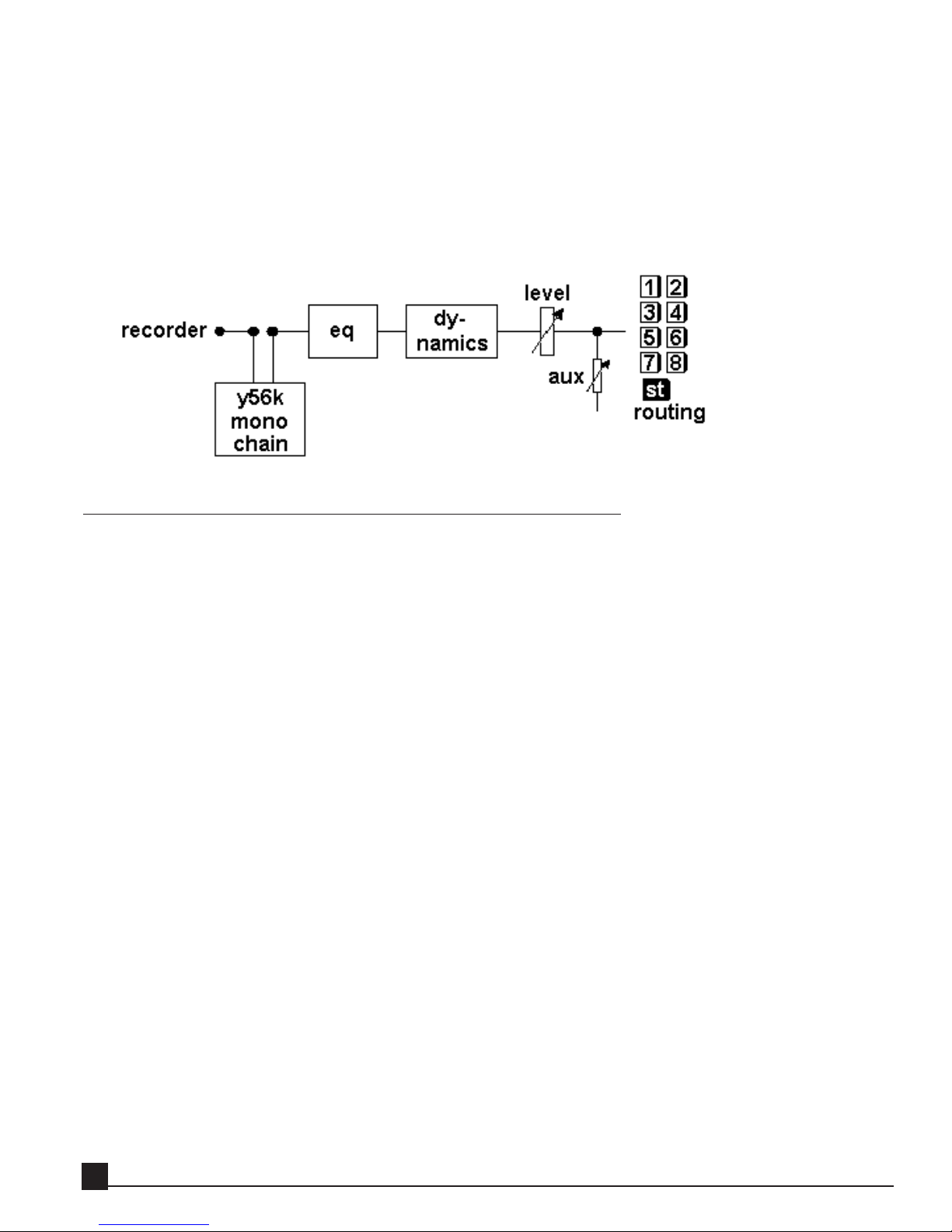
You can use the above patching scheme to insert a stereo effect on a mono AW channel. To do this, while
performing step 14 turn the AUX1 to pre-fader mode. In addition, switch off this channel’s routing to the
stereo master channel. This patching type allows you to use TrueVerb in Thru mode, for example. Refer to
the TrueVerb section in the Y56K Effects chapter for more information.
Y56K User Guide
23
Page 24

The patching scheme in this case will look like this:
Insert a mono De-Esser, REQ and L1 Limiter on a vocal track as described in the “Using an effect chain as
a mono channel insert” section, and then use an auxiliary to insert a stereo TrueVerb as described above.
This will sound close to using all these effects in stereo, but will use less DSP resources.
Try using the AW’s buses to route several channels to one Y56K effect chain. This is a great way to send
drum tracks through TrueVerb to “put them in a room”.
Using the Y56K’s lightpipe I/O
The Y56K can act as a lightpipe (or ADAT) I/O card for the AW’s channels and also apply its effects to audio
arriving over the Y56K’s lightpipe from the ADAT or to audio sent over its lightpipe to ADAT.
In the effect chain, select ADAT as the audio source from the Y56K Main SRC column to direct the specific
effect chain pair to “listen” for audio on the Y56K’s lightpipe input.
All audio received by the Y56K is echoed (post the effect chains) to the card’s lightpipe output.
Patching lightpipe input
Verify that the Y56K effect chain’s SRC is set to ADAT so the effect chain processes audio from the Y56K’s
ADAT input.
Y56K User Guide
24
Page 25

Go to the D.in Setup page. The Y56K’s installation slot displays “Waves.”
Synching ADAT to the AW
1. Make sure the Y56K’s ADAT output is connected to the ADAT machine.
2. Go to the AW’s D.in page, which allows selection of the sync type used by the Y56K, AW, and
ADAT.
3. Click INT to select the AW as the clock master.
Patching the audio signal to an AW channel
The following procedure assumes effect chains 1 and 2 have been set to receive audio from the
ADAT.
1. Go to the MIXER CHANNEL INPUT ASSIGN section on the Patch IN page.
2. Move the CURSOR to the desired channel on which to receive an ADAT signal.
3. Rotate the [DATA/JOG] dial to select SL1-1 or SL2-1 (depends on the Y56K’s installation slot).
4. This outputs audio from effect chain 1 to the selected AW channel.
5. Since ADAT channels are received in stereo pairs, repeat the previous steps to patch the second
ADAT channel.
Patching lightpipe output
No special preparations are needed. The Y56K always sends its processed output through to its ADAT lightpipe output connector.
Y56K User Guide
25
Page 26

Chapter 4: Y56K pages
This chapter explains all functions in the Y56K’s pages.
Y56K Main page
When accessing the Y56K for the first time after system boot, the Y56K Main page is displayed (below). In
this central program page, you can:
load effects to effect chains;
select the input source to the chains;
group the chains in stereo pairs;
save and load settings;
access effect Properties and other Y56K pages.
1. Special page
Click this button to open the Special page. Refer to the “Special page” section for more information
2. Y56K Main Preset name
This header displays the Y56K Main preset name.
NNotote!
e! Changing scenes in Automix mode does not update the Y56K preset names.
3. Y56K Main Load and Save
Y56K Main Load button
Click this button to open the Load page to load an effect chain or Y56K Main preset (factory-set or
user-created).
The following information is maintained in a Y56K Main preset:
1. Preset Name
2. Source selection for each chain
3. Grouping selection for each chain
Y56K User Guide
26
Page 27

4. Effect chains and chain bypass/enable status.
5. Effect bypass/enable status, and effect presets.
Refer to the “Load/Save dialog windows” section in the “Y56K user interface” chapter for more information.
Y56K Main Save
Click this button to open the Save page to save an effect chain or Y56K Main preset. The same information is saved as noted in the Y56K Main Load section above.
Refer to the “Load/Save dialog windows” section in the “Y56K user interface” chapter for further
information.
4. Effect block
An effect block displays either the effect’s abbreviated name or a blank rectangle if empty. Clicking an effect
block opens a popup menu; the contents depend on whether it is empty or contains an effect.
Clicking on an empty Effect Block
Clicking on an empty effect block opens the New Effect popup menu (below), allowing effect selection and insertion.
EEffffecect list
t list
The upper section of the menu lists the effects that can be inserted into that block. The menu
list is dynamically updated according to:
Stereo/mono effect chain: Effects that can be inserted only into stereo chains are not dis
played for a mono chain and vice versa. For example, TrueVerb can be inserted only into a
stereo effect chain.
Available DSP resources: Only effects that can function within the current available DSP
resources are displayed. When the DSP is full and no additional effects can be inserted, the
menu displays “DSP Full.”
Y56K User Guide
27
Page 28

NNootte!
e! The Y56K has two DSPs. The first DSP is dedicated to effect chains 1-4, the second to
effect chains 5-8. When the DSP serving effect chains 1-4 is full, you can still load effects to
effect chains 5-8 and vice versa.
PPast
astee
Choose Paste to paste the clipboard’s effect and settings into the selected effect block.
NNootte!
e! Pasting an effect is possible only when the Y56K’s clipboard contains and effect and
when current available DSP resources allow the effect to be pasted.
Clicking on an effect block containing an ef
fect
Clicking on an effect block containing an effect opens a popup menuthe Edit Effect popup menu
(below) consisting of the following functions.
PrProoppeerrtties
ies
Choose Properties to open the effect’s Properties page to adjust its parameters.
BByyppass/E
ass/E
nab
nablele
Select Bypass/Enable to toggle the effect between the two states. A bypassed effect block is
gray.
DDeelelette
e
Choose Delete to delete the effect from the effect block, leaving it empty.
CCooppy
y
Choose Copy to copy the effect and its settings to the Y56K clipboard, allowing it to be pasted to another effect block.
CCut
ut
Choose Cut to delete the effect from the selected block and copy the effect and its settings to
the Y56K clipboard, allowing it to be pasted to another effect block.
PPast
astee
Choose Paste to paste the effect and its settings currently in the clipboard into the selected
effect block.
NNootte!
e! When pasting a stereo effect onto a mono effect chain and vice versa, the Y56K will
paste the effect’s appropriate counterpart when applicable.
Some effects, like TrueVerb or L1+, can only be inserted to stereo effect chains.
Y56K User Guide
28
Page 29

5. About page
Click this button to open the About splash page, containing the Y56K software and hardware revisions and
the card’s serial number.
6. Effect chain popup menu
This column indicates the effect chain number. Click on an effect chain number button to open a popup
menu (below) that bypasses/enables the effect chain and clears effects from the chain.
Bypass
Select Bypass/Enable to toggle the effect chain between these two states.
Clear
Choose Clear to remove all effects from the effect chain.
Copy
Choose Copy to copy the entire effect chain to the Y56K clipboard, allowing its content to be pasted
to another effect chain.
Cut
Choose Cut to delete the entire effect chain and its content to the Y56K clipboard, allowing it to be
pasted to another effect chain.
Paste
Choose Paste to paste the effect chain content currently in the clipboard into the selected effect
chain.
NNotote!
e! When pasting a stereo effect chain content onto a mono effect chain and vice versa, the Y56K
will paste the effects’ appropriate counterpart when applicable.
Some effects, like TrueVerb or L1+, can only be inserted to stereo effect chains.
Y56K User Guide
29
Page 30

7. SRC - Source Selection
Click on an effect chain’s SRC button to open a popup menu (below) allowing the audio source for that
effect chain pair to be switched between the card’s lightpipe I/O and the AW.
Console
Select Console to switch the input of the effect chain pair to the AW. The effect chain pair now “listens” for audio from the AW.
NNotote!
e! Source switching applies to effect chain pairs. For example, switching effect chain 1 to ADAT
also switches effect chain 2.
ADAT
Select ADAT to switch the input of the effect chain pair to the ADAT. The effect chain pair now “listens” for audio from the ADAT input.
NNotote!
e! Source switching applies to effect chain pairs. For example, switching effect chain 1 to ADAT
also switches effect chain 2.
8. Group selection
Click an effect chain’s GRP button to open a popup menu (below) that combines two effect chains into a
stereo pair.
Mono
Select Mono to break the stereo pairing of the two effect chains. The two effect chains now operate
as independent mono effect chains.
Stereo
Select Stereo to combine the two effect chains into a stereo pair. The two effect chains now operate
as one stereo pair.
Y56K User Guide
30
Page 31

Switching between mono and stereo
Switching an effect chain with inserted effects between mono and stereo (either way) allows you to
substitute its inserted effects with their mono/stereo counterpart effects and copies their presets to
the new effects.
SSwwititcching a mono e
hing a mono effffecec
t c
t c
hain t
hain t
o st
o steerreoeo
Switching a mono effect chain to stereo displays the following dialog box:
Clear
Choose Clear to delete all effects from the chain and switch it to stereo grouping.
If the adjacent effect chain (i.e., the one the selected effect chain will be paired with) contains effects, they will be deleted as well. For example, switching effect chain 1 to stereo
while effect chain 2 contains effects, also clears effect chain 2.
Clear results in an empty stereo effect chain.
Chn
Click on one of the Chn buttons to copy the effects from the selected mono chain to the
new effect chain, switching it to stereo.
For example, to convert two mono effect chains (1 and 2) each with their own effects to
stereo:
1. Select Stereo from the GRP menu.
The MONO TO STEREO dialog box appears.
2. Click on the Chn 1 button to switch the effect chains to stereo grouping and copy the
effects inserted on Chn 1 to the new stereo chain.
The effects inserted in chain 2 are deleted.
3. Click the Chn 2 button to switch the effect chains to stereo grouping and copy the
effects inserted on Chn 2 to the new stereo chain. The effects inserted in chain 1 are
deleted.
The result of this operation is a stereo effect chain containing the same effects as the previous mono chain.
Y56K User Guide
31
Page 32

Special page
Click the Special button on the Y56K Main bar to open the Special page (below). Click the Main button to
close the Special page and return to the Y56K Main page.
This page has three functions:
DSP system usage
This section displays the current DSP resources used as a bar graph and as a percentage of the total still
available. These displays are updated as effects are added and deleted from chains.
Chain Delay
Some effects, such as the L1 and Renaissance Compressor, delay the audio signal by a few samples. The
Chain Delay displays the accumulated delay on each effect chain so other tracks can be synchronized by
being delayed the same amount.
Update Mode
Click this button to switch the Y56K card to update mode, allowing the installation of new software or
effects.
This button is used ONLY to switch the Y56K card to update mode. If this button is clicked by mistake,
click Cancel in the Confirmation alert dialog box; pressing OK switches the card to update mode. Refer to
the “Updating the Y56K” chapter for more details.
Y56K User Guide
32
Page 33

Chapter 5: Y56K effects
This chapter introduces the WaveSystem and explains how to use the Y56K effect processors. The
WaveSystem includes controls common to all Y56K processors and our other software products.
General
All Y56K effects share the functions shown in each effect’s top WaveSystem toolbar and bottom Info Line.
Familiarize yourself with these controls to enhance your workflow.
WaveSystem
Bypass
This button toggles the effect on and off. Bypassed effects are shown with gray effect blocks.
Setup A, Setup B, [A→B]
Click the Setup A/Setup B button to compare two settings. Loading a setup into the Setup B position
does not affect the Setup A position, or vice versa.
You can modify the settings in Setup A, copy them to Setup B by clicking the Copy to B button
(A→B), and then compare them. Similarly, you can copy Setup B into Setup A by clicking the same
button.
NNotote!
e! When an effect is copied, only its active (currently visible) setup is copied with it.
Load and Save
Click the Load and Save buttons to open their respective dialogs. Refer to the “Load/Save dialog windows” section in the “Y56K user interface” chapter for more information.
LLooad
ad
Click this button to open either a factory or user preset.
SaSavve
e
Click this button to save the preset.
Chain navigation arrows []
Click the left arrow [ ] to close the current effect’s properties page and open the previous effect’s
properties page in the same chain.
Click the right arrow [ ] to close the current effect’s properties page and open the next effect’s
properties page in the same chain.
Waves logo
Click on the Waves logo to exit the effect and display the Y56K Main page.
Y56K User Guide
33
Page 34

Info Line
The Info Line is displayed at the bottom of each effect’s Properties page.
1. Chan: Effect chain(s) the effect is inserted in.
2. Src: Effect chain’s audio source.
3. Ins: Effect chain’s block number in which the effect is inserted (1–5).
4. Effect name
Y56K User Guide
34
Page 35

L1-Limiter / L1-UltraMaximizer
Introduction
The L1-UltraMaximizer is a sophisticated, audio-processing tool kit that combines an advanced peak limiter, level maximizer, high-performance re-quantizer, and the Waves IDR (Increased Digital Resolution)
wordlength reduction system. The L1-UltraMaximizer is intended specifically for mastering, digital editing,
multimedia, and other applications requiring high-quality limiting and/or re-quantization.
While conventional limiter operation is well understood, the L1-UltraMaximizer is capable of a very fast,
overshoot-free response. Once the limiter threshold is set, the user can define the actual peak level allowed
for the processed signal, which makes limiting and level re-scaling a one-step process. For mastering, the
processed signal’s peak level is normally set to, or slightly below, 0 dB.
Y56K User Guide
35
Page 36

We recommend placing the L1 last in the processing chain to maximize the signal’s sonic integrity. If not
placed last in the chain, the L1 will still work but the absolute brick-wall limiting and benefits of IDR requantization will be compromised; further limiting may be necessary to maintain the original level.
Processing after the L1 will likely increase the signal’s wordlength and peak values.
L1 component plug-ins
As of this release, the L1 has two plug-in components:
L1-Limiter - mono/stereo wideband limiter without IDR (track insert, voice or instrument limiter, SFX
maximizer)
L1-UltraMaximizer- the full mastering plug-in with limiter and all IDR options (CD mastering, multimedia authoring)
Important Digital Audio Facts for Optimal L1 Use
Maximum Level
The maximum level of a digital signal is determined by the song or track’s highest peak value.
Simple normalization finds the highest peak, then raises the entire signal so that this peak is at the
maximum value. Many of these peaks, however, may be of short enough duration to be reduced by
several dB without audible side effects. This allows the entire level to be raised several dB, resulting
in a higher average signal level.
The L1-UltraMaximizer avoids overshoot by utilizing a look-ahead technique that anticipates and
reshapes signal peaks to minimize audible artifacts. This allows the L1 to be used with absolute confidence in situations that require brick-wall limiting.
Maximum Resolution and IDR™
DSP that alters the original digital data (mixing, gain changes, EQ, dynamic processing, etc.) typically increases the bit width required to represent the signal. Conventional truncation reduces signal
resolution with each process, which deprives the signal of spaciousness and transparency.
The Waves IDR process, based on Michael Gerzon’s noise-shaping, re-dithering technique, prevents
this loss of critical low-level detail. IDR offers two dither types and three noise-shaping curves to
optimize processing of a wide variety of applications and source material. It signifies a major
advance in preserving and actually increasing the resolution of a processed digital signal. IDR can be
used during each process (i.e.,16-bit), or once at the end of a high-resolution chain (i.e., 24-bit), to
ensure the maximum resolution of the final signal. IDR is particularly beneficial when data is deliberately re-quantized from 24- to 16-bit, 16-bit to 8-bit, etc. Dithered outputs of 20-,16-,12-, and 8bit are available from the L1-UltraMaximizer. This is very helpful during final file preparation, mastering, and quantization or re-quantization.
Y56K User Guide
36
Page 37

Using the L1
The Peak Limiter
Pass audio through the L1.
Listen to the output of the L1.
Set the limiter Threshold by dragging the left triangle (Threshold) down or by rotating the
[DATA/JOG] dial when the CURSOR is on Threshold. Leave the Out Ceiling setting at the
maximum value: 0 dB. When the signal exceeds the threshold, the gain reduction is indicated on
the single Attenuation meter to the right.
Set the threshold about 4–6 dB lower than the peaks in the Threshold meters. The Attenuation
meter displays 4–6 dB of peak limiting.
As the Threshold is pulled down, the output level goes up. To begin with, leave the Out Ceiling setting at 0 dB (the maximum peak output).
Note that the output level is significantly increased. If the threshold is -12 dB, the signal has been
boosted 12 dB (not necessarily recommended). Typically, several dB of limiting is virtually inaudible
and raises the average output signal level enough to improve overall response.
Only the signal above the threshold is limited; signals below the threshold have a constant gain
change determined by the difference between the Threshold and the Out Ceiling. This is how the L1
maximizes the level while maintaining the desired headroom.
Release Time and Attenuation Meters
Adjust the Release time to suit the application: 1 ms for most sources, 3–7 ms for mastering, and as
high as 30 ms for voiceover. The release time controls how fast the L1 recovers to constant gain after
encountering a peak. Distortion or fuzziness can sometimes be reduced by increasing the release
time.
Y56K User Guide
37
Page 38

The IDR Section
IDR ™
IDR ™ technology was designed by Michael Gerzon, a Gold-medal AES fellow, and a world authori-
ty in psychoacoustics. He also invented the SoundField microphone, and was one of the major contributors to Ambisonics™. The design of IDR is a result of his long-term research, dating back to
1982, with many other leading experts in digital resolution enhancement technologies.
QQuant
uantizizee
Quantize controls the final bit depth (8,12,16, 20, 24) of the output of the L1; it is not related
to the input bit depth. Waves plug-ins maintain a 48-bit resolution during all processing. The
Quantize setting captures the best data possible for the selected bit depth.
16-bit
Set the Quantize value to 16-bit to save the final output to DAT or CD.
8- and 12-bit
Set the Quantize value to 8- or 12-bit to save the final output for low-resolution multimedia. The file should be sample-rate converted prior to level maximization and dithering.
20-bit
Set the Quantize value to 20-bit to save the final output to a 20-bit storage medium.
24-bit
Set the Quantize value to 24-bit to save the final output to a 24-bit storage medium. This
setting is best suited for certain archival media or intend on a subsequent 24-bit file
bounce.
Y56K User Guide
38
Page 39

DDithe
itherr
The L1 provides three dither options:
None
No dithering occurs and the signal is truncated normally which provides significant nonlinear distortion at low levels.
Type1
Type1 dither adds some noise, causing a 5 dB increase in background noise compared to
the None setting, but completely eliminates all low-level distortion and signal-dependent
modulation effects. The resulting low-level signal is high resolution, transparent ,and
clean.
Type1 is the first technique optimized for every processing stage, allowing cascading and
subsequent signal processing. Type1 minimizes side effects with stereo signals.
We recommend using Type1 for 20- and 16-bit files and other high-quality mastering
applications. Combining level maximization (peak controlling) and IDR processing gives
16-bit files created from 20- or 24-bit masters the apparent resolution of 19 bits (an 18
dB improvement).
T
ype2
Type2 dither adds virtually no audible noise and is 5 dB quieter than Type1; it does add
some low-level distortion. This distortion, however, is lower than without dither. Type2 is
black with no input signal: there is no dither signal without input (also called auto-blacking dither). Type1 is a constant output signal dither noise, and is on even without input.
NNois
ois
e S
e S
haping
haping
Noise shaping is a technique that shifts the noise frequency to a frequency range more difficult for the ear to perceive. This can both decrease the perceived amount of noise and
increase the perceived resolution.
The L1’s IDR section includes three noise-shaping options that shift the noise to frequencies
above 15 kHz, where our ears are least sensitive, and reduce the noise at lower frequencies.
The options differ in the amount of shifting imposed.
None
No noise shaping results in high audible hiss and distortion levels when used without
dither.
Moderate
The Moderate setting reduces perceived noise by about 6 dB and slightly reduces audible
distortion when dither is not used. The Moderate setting is appropriate for 8-, 12-, and
16-bit files.
Normal
The Normal setting reduces perceived noise by about 8.5 dB and slightly reduces audible
Y56K User Guide
39
Page 40

distortion when dither is not used. We recommend using the Normal setting for most
applications and bit depths.
Ultra
The Ultra setting provides the most noise reduction: approximately 10.5 dB. Ultra is suitable for use only at the last stage of mastering high-resolution files (16-bit and higher) on
high-quality digital media. We do not recommend the Ultra setting if subsequent editing
is required or the file is destined for media with poor error correction (fortunately, this
type of media is not commonly encountered anymore).
DDigigital/A
ital/A
nalog D
nalog D
omain
omain
In the Digital Domain position, no sample exceeds the Out Ceiling value. After analog conversion, however, it is possible to have higher peaks than in the digital domain. This is due to
complex digital audio issues involving “peaks between the samples.” Most high-quality digital-to-analog converters have at least 3 dB headroom to allow for these peaks; many have 12
dB.
Use the Analog Domain position to have absolute control over any peak that occurs in both
the analog and digital domains.
16-bit (and higher) Mastering
All processing (i.e., EQ, sample-rate conversion, dynamic changes, etc.) must be done prior to the L1UltraMaximizer, which should be the last process in the chain. The reason for this is that dithering should
occur only once before the master recorder or final file bounce.
Recommended Settings
1. Use the input faders to balance the left and right channels.
2. For 16-bit and higher input files, set the Threshold for about 4–6 dB of Gain Reduction in the
Atten meter.
3. Set the Output Ceiling to the maximum peak output desired. The Output Ceiling can be set to 0
dB without clipping. We recommend -0.3 dB for CDs (see the Peak Clipping section for more
information).
4. Leave the Release time set to the default (1 ms).
5. Set the Quantize output to 16-bit for CD/DAT or 20-/24-bit for higher archival or mastering
media.
6. Set the Dither to type1 or type2. We recommend IDR type1 for most high-resolution applications.
7. Set the Shaping (Moderate, Normal, Ultra, None). Ultra and Normal are recommended for most
high-resolution applications.
8. Select Digital or Analog Domain mode.
We recommend the Analog Domain mode for all final production masters to avoid clipping from
poorly designed DA converters without compromising any L1 processes. For more information, see
Digital/Analog Domain in the IDR controls chapter.
Y56K User Guide
40
Page 41

RCL - Renaissance Compressor
The Renaissance Compressor is a classic, warm compressor/expander with a simple interface. The Waves
ARC™ compressor algorithm dynamically selects the optimal release time for a wide range of inputs. As levels fluctuate, ARC responds much like the human ear and produces high RMS levels (lower peak-to-RMS
ratio) with greater clarity than most compression algorithms.
Most compressors use one set of time constants to handle overall RMS levels and peak transients. ARC analyzes overall levels and peak transients separately and sets a faster release time for peak transients than for
levels over the compression threshold. Dynamic variation of the release time delivers more constant compression with fewer artifacts, allowing the Renaissance Compressor to function simultaneously as a leveler
and fast compressor.
Classic 5- control setup is at the core of the interface, supplemented by a Release Mode button
(ARC/Manual), plus the gentle Character control (Warm/Smooth), and the Behavior control
(Opto/Electro).The Classic 5 interface includes: a Release Mode button (ARC/Manual), a gentle Character
control (Warm/Smooth), and Behavior control (Opto/Electro).
Release Mode
This button selects between Auto Release (ARC) and Manual.
ARC mode uses the Waves auto-release technology. You set the release time as an overall scaling factor and
ARC varies it from there depending on the input signal. Its character is similar to very responsive vintag
program compressors but also works extremely well for individual tracks.
Manual mode is fully manual, with no ARC (Auto Release Control).
Y56K User Guide
41
Page 42

ARC ™ (Auto Release Control)
ARC is a system designed to dynamically choose the optimal release value for a wide-ranging input.
ARC reacts much the way a human ear expects, and can produce increased RMS level with greater
clarity.
In many uses of compressors, the exact choice of time constants is set as a careful choice of reaction
to RMS and peak transients. To allow more constant compression with fewer artifacts, the release
time must change to control different parts of the signal. In ARC, similar to the human ear, RMS
and peak transients are analyzed and reacted to differently. In general, the release is faster for peak
transients and slower for the overall RMS level.
For instance, with a relatively constant compression of 4dB, peaks beyond this need faster release
times. The ARC system does exactly this, varying the release time to fit the ear’s expectations while
increasing RMS, and without creating distracting artifacts. In this way, the Renaissance Compressor
can serve as a leveler plus a fast compressor simultaneously. This feature also serves gentle mastering
applications quite well, but generally with slower release times.This button selects between the AutoRelease (ARC) and Manual modes.
ARC mode uses the Waves auto-release technology: the user sets the release time as an overall scaling
factor and the ARC algorithm varies the release based on the input signal. Its character is similar to a
responsive, vintage program compressor but also works well for individual tracks.
Manual mode disables ARC.
Compression Behavior
Electro mode decreases the release time as the gain reduction drops from 3 dB to 0. As the gain reduction
increases above 3 dB, the release time increases, which makes the compressor act more like a leveler. With
moderate compression, the Electro mode produces a significant increase in RMS level, which makes it ideal
for applications requiring loud overall levels (i.e., voiceover and rock music).
Opto is the inverse of Electro: the release time increases as the gain reduction drops from 3 dB to 0. As gain
reduction increases above 3dB, the release time decreases. This behavior models vintage compressors with a
sharp transient attack and minimal sustain, used for drums and similarly percussive instruments.
Character
The Character button toggles between Smooth and Warm low-frequency characteristics.
The Warm setting adds low-frequency harmonics as the gain reduction increases. The Smooth setting does
not add harmonics and preserves the natural character of the signal.
Y56K User Guide
42
Page 43

Threshold
The Threshold value is displayed in dBFS (dB below Full Scale digital). 0 dBFS is the highest level supported
by the digital format.
The Threshold sets the level above which the soft-knee compression or expansion engages. The threshold
slider is beside the Input Meters.
NNotote!
e! The Renaissance Compressor uses a soft-knee curve, so compression and expansion begin with sig-
nals 3 dB lower than the Threshold.
Ratio
The Ratio control adjusts the compression or expansion ratio for signals above the Threshold level. A wide
range of compression and expansion ratios is available: compression = 1.01:1 to 50.0:1; expansion = 0.99:1
to 0.50:1. The Ratio fader is beside the Gain meter.
Y56K User Guide
43
Page 44

Attenuation
The Attenuation meter shows the instantaneous gain change. Compression causes negative gain while
expansion causes positive gain. The meter includes Peak Hold values at the bottom (click to reset).
Compressor Attack
The Attack parameter controls the onset time for the compressor or expander to reach its full gain alteration. The Attack value can be set in the range 0.5–5000 ms.
Compressor Release
The Release parameter controls the time (ms) from peak gain alteration to 0 dBthe release time of the compressor (ms). The release characteristic is linear when ARC is off off and is scaled to the input when ARC is
on. When ARC is on the release value acts as a scaling factor for ARC.
Y56K User Guide
44
Page 45

Gain
The Gain parameter adjusts the compressor’s output gain from +30 to -3 dB in 0.1 dB increments. Output
meters use a logarithmic scale from 0 to -60 dBFS. Click the Peak Hold values at the bottom to reset them.
Limiter Section
The Renaissance Compressor has an L1-style limiter at the output stage and works well in compression or
expansion modes. The Threshold and Output Ceiling values are set to 0 dBFS and the limiter activates only
when the level exceeds 0 dBFS. The limiter functions in addition to the compression and the total gain
reduction is shown in the attenuation meter.
Y56K User Guide
45
Page 46

REQ - Renaissance Equalizer
Filter Descriptions
Resonant Shelf Filters
Michael Gerzon proposed a resonant shelf filter in a confidential paper to Waves in 1994. Analog filters (i.e., Pultec) had already achieved this type of EQ behavior by cutting and boosting simultaneously. Gerzon defined a method to include this acoustically desirable behavior into a single digital
filter, but did not live to see it implemented. We named several shelf presets in his honor, although
our implementation combines his ideas with Pultec filter characteristics.
These resonant shelf filters differ from their traditional counterparts in the visibly obvious curves of
the shelf and the variable Q, which alters the steepness of the slope. These filters share some qualities
with the parametric filters described below.
With the Q set to the maximum value of 1.41 octaves, the slope is steepest and the resonant parts of
the curve are at their most extreme. Gerzon suggested a Q of just under 1.00 as a pleasing nominal
value for most applications. The classic Gerzon Shelf setting is a Q of 0.99, with low and high shelving set to 250 Hz and 4 kHz, respectively.
Cut filters
Cut filters are sometimes called pass filters in the USA, particularly in synthesizer documentation (a
high-pass filter is the same as a low-cut, etc.).
A variable Q value differentiates these filters from typical cut filters. The Q changes the slope of the
line and includes a bump in the frequency response, allowing the filter to be more musical while still
fulfilling the cut function.
At first glance, it might seem that a steep filter would be best to remove unwanted frequencies.
Although a steep, brick-wall filter is effective at cutting high frequencies, it can cause significant
phase shift and make the sound unnecessarily dull. By allowing a few of the neighboring frequencies
Y56K User Guide
46
Page 47

to remain, the target frequencies are still removed and the resulting sound is sweeter and brighter.
NNotote!
e! Steep, brick-wall filters are still applicable to multimedia or other band-limited tasks, such as
digital conversions. The REQ filters are designed for pro audio and other musically demanding
applications.
Bands 1 and 6 are third-order filters (Q=1, 18 dB/octave). When the Q is higher than 1, the notch
and bump yield a higher slope than a third-order filter, but still pass some of the higher harmonics,
although reduced in amplitude. At the lowest Q (0.71), the slope is slightly less than a second-order
filter (10 dB/octave).
Parametric (Bell) Filters
Most people are familiar with the parametric equalizer invented by George Massenberg. The parametric filter has three controls: center frequency, bandwidth (or Q), and gain (boost or cut). Almost
without exception, they have symmetrical response characteristics: boost and cut have the same
“bell” shape for a selected bandwidth or Q setting. An asymmetrical filter has a different shape for
boost and cut for the same Q setting.
Since it is common to boost a relatively wide bandwidth for aesthetic tonal correction and cut a narrow bandwidth to remove artifacts (i.e., feedback, excessive vocal sibilance), an asymmetrical
response is perhaps more useful in the analog domain. Asymmetrical filters have been described by
several audio researchers and designers (including Mitra, “Hutch” Hutchinson, and others), but not
included in commercial products to our knowledge. Waves chose to include this type of filter simply
because it sounded better for professional use.
The Controls
When the REQ is first inserted, all bands are switched In by default except Band 1, which is intentionally
Out because it is a low-cut filter.
Individual band controls
The small controls beneath the frequency curve display are the Value Windows for Gain, Frequency,
and Q for each band. At the bottom of each column is the control to switch each band In or Out,
and to choose the filter type.
GGain
ain
The Gain may be adjusted ±18 dB, in increments of 0.1 dB, and is displayed in the frequency
response graph.
FFrreq
eq
The Frequency control displays the each band’s center frequency for parametric filters or the
corner frequency for shelving filters. The Frequency control values are adjustable in 1/96
octave increments, rounded to the closest integer frequency (Hz).
Y56K User Guide
47
Page 48

Q shap
Q shapee
The Q control displays the Q value, which functions differently for each filter type:
Bell - Q corresponds to the width of the frequency range.
Shelf - Q controls the slope of the side of the shelf and the resonant dips and
peaks.
Cut - (bands 1 and 6 only) Q controls the slope of the cut filter (from about 10
to 18 dB/octave) and the bump in the slope.
A higher Q corresponds to a narrower bell shape or steeper cut for shelf filters.
In the Renaissance Equalizer, the resulting bandwidth for a given Q value is different for positive and negative gain settings. For negative gain, the filter’s asymmetrical property,
described above, yields a narrower bandwidth (almost a factor of 2) than an equalizer with
symmetrical behavior.
IIn-o
n-o
ut / F
ut / F
ilt
iltee
r T
r Tyyppee
At the bottom of the controls, a row of buttons toggles each band In or Out, and sets the
Filter Type. Remember that not all bands do not have the same filter types available.
Bands 1, 6: cuts, bells, shelvescut, bell, shelf.
Bands 2, 3: bells, low shelf.
Bands 4, 5: bell,s and high shelf.
Click the Filter Type button or the [ENTER] key to toggle through the options for that band.
Click the band number to switch the band In or Out; the button lights when the band is In.
Trim
48-bit processing allows using some headroom to completely avoid internal clipping. The REQ automatically eliminates clipping in each band. Such clips, although not indicated on input or output
meters, certainly affect the signal. This feature renders input gain controls unnecessary; only an output gain control is required to prevent clipping the output by over-equalization of a hot signal.
Fortunately, the same headroom allows the REQ to calculate exactly how far over 0 dBFS to allow a
signal .a signal has occurred.
The Trim button is in the center below the meters (calibrated in dB). The clip light is above the
meters. In the picture above, the Trim button indicates a signal 12 dBFS. The positive value indicates
there is headroom available and the clip light is off.
Y56K User Guide
48
Page 49

To Trim the faders, click the Trim button once to automatically move the faders by the value shown
in the button. This resets the output faders to the value shown, up to the maximum positive gain
allowed (for reasonable safety in such matters), which is 12 dB. To reset the Trim (and the meters)
without changing the fader values, click either one of the clip lights.
Y56K User Guide
49
Page 50

DSR - DeEsser
Orators and singers commonly produce prominent ess, ch, and sh sounds, also known as sibilance, while
using a microphone. Most vocal recordings contain these undesirable artifacts due to microphone proximity, strong vocal delivery, bad equalization, or speech impediments. Wind and other musical instruments can
also create shrill, high-pitched noise that falls into this category.
The DeEsser can help attenuate these high-frequency artifacts using steep sharp filters in the Sidechain filters and either Wideband or Split audio paths. The DeEsser is suitable for processing full mixes, solo vocal
tracks, and instrumentals. Applying gentle de-essing to a complete mix is often effective at reducing sibilance without filtering important high-frequency information.
Quick Start
To reduce sibilance in a male vocal track:
1. Click the Load button and select the “Male Ess” factory preset.
This preset sets the Sidechain frequency to 4500 Hz, the frequency nearest around which the male
sibilance lies.
2. Reduce the threshold until the “ess” sounds are sufficiently attenuated.
Attenuation occurs when the threshold slider is below the peak of the input meter (energy detector). The
attenuation meter shows the instantaneous gain reduction applied to the audio (dB). An infinite-peakhold feature displays the highest level of attenuation (click to reset).
3. To fine-tune DeEsser, click the Monitor button to display switch to the Sib.Att. mode allowing you to
monitor the side chains.
4. Choose either HighPass or BandPass from the Sidechain filter modes. The HighPass filter mode is suitable
for attenuating a full range of sibilance. The BandPass filter mode is suitable for isolating and attenuating
a specific narrow band of high frequencies.
5. To find the center frequency of the sibilance, adjust the Freq control while boosting the threshold.
6. Switch monitoring back to Output mode and listen to the result.
Y56K User Guide
50
Page 51

DeEsser Controls
Thr
eshold and Energy Detector
This meter displays the sidechain energy in dBFS. The energy meter and threshold slider are aligned
for easy adjustment and visual feedback. The threshold sets the level above which attenuation occurs
in the sidechain. To adjust the threshold, drag the slider down or lower the value in the Threshold
field until the sibilance is sufficiently reduced.
NNotote!
e! Lowering the threshold too much results in a muffled sound. Listen to the track in context
because the other tracks will mask the sibilance
Attenuation
This meter displays instantaneous gain reduction (attenuation in dB). The attenuation meter
includes a Peak Hold value at the bottom (click to reset).
Y56K User Guide
51
Page 52

Output
An infinite peak hold value shows the highest output level (click to reset).
Audio
The Audio button toggles between Wideband and Split compression modes. Wideband mode attenuates the entire audio band. Split mode divides the audio into low and high frequency signals and
attenuation is applied only to the high-frequency signals. Split mode is most commonly used for deessing.
Frequency
Sets the Sidechain filter frequency.
Sidechain
The Sidechain button toggles between a HighPass and BandPass filter. The HighPass filter operates
on all frequencies above the Sidechain frequency; the BandPass filter operates only on a narrow band
around the Sidechain frequency.
Monitor
The Monitor button toggles between listening to just the Sidechain signal and the entire output.
Y56K User Guide
52
Page 53

TV - TrueVerb
Quick Start
TrueVerb can create a true, natural-sounding room around a sound source by controlling room size, frequency response characteristics, and distance from the source. TrueVerb differs from other reverb processors
in that it works in a Thru mode in addition to the traditional Send/Receive mode.
In Thru mode, place TrueVerb on the Insert point of a track, Aux, or Master. This is because the effected
sound is not mixed with the original but instead, the original signal passes through TrueVerb. Of course
TrueVerb can be used as a standard send/receive reverb, but the Distance parameter will not be properly
perceived.
Example 1: Thr
u mode – Dry mix
A soundboard concert mix is too dry and needs some of the room’s reverberation. Patch the
TrueVerb into the stereo Insert point of the Master fader. Determine the room size, desired acoustic
characteristic (bright or dull), and distance from the stage. This also works well for classical or jazz
sessions recorded in a dead room.
1. Open a relatively dry, fully-mixed stereo song without reverb. A multitrack stereo mix without
reverb, acoustic music, jazz tracks, or a concert sound board mix will also work.
2. Insert TrueVerb on the Master fader.
3. Load the Medium Concert Hall setup.
4. Adjust the Distance control, and the desired acoustic characteristic (bright or dull)
At first, this may sound different from other reverbs you have used. By increasing the Distance
parameter, the sound source seems to move away from you. TrueVerb simulates the distance while
maintaining a constant perceived reverb level. In a real room, the level decreases with increasing distance from the source. Take your time and experiment with the Distance parameter and monitor
levels to experience the spatial dimensions created by TrueVerb.
Y56K User Guide
53
Page 54

Example 2: Thru mode – Drums submix
A drum submix needs a better room sound. This also works well for vocal, guitar, and other
submixes.
1. Select a two-channel drum submix.
2. Mute all other tracks and insert TrueVerb on the Stereo Master.
3. If the drums are on an Aux, insert TrueVerb on that Stereo Aux of the submix. Route all tracks to
the submix bus, not to the output; listen only to the Stereo Aux output and do not mix in any
direct sound from the individual drum channels to your Main Out.
4. Select the setup file Drum Room. This simulates a tight drum room that is not too bright or
warm. Bongos and other solo percussion work well in this room type (high density with a short
reverb time).
TrueVerb Interface
T
ime Response graph
Time Response graph shows Early Reflections, PreDelay, Reverb tail, and all relative levels. The horizontal axis shows time (ms). From left to right, the graph shows the Direct sound (the first vertical
bar on the left edge), the spread of early reflections on the left as lines, then the Reverb, overlapping
the reflections. As the PreDelay value changes, the Reverb shape moves to show the time offset.
Time Response controls
The Early Reflections and Reverb controls are below the Time Response graph.
DDime
ime
nsion
nsion
Dimension changes the character of the Early Reflections to simulate an N-dimensional
space. A Dimension value of 2 generates early reflections corresponding to a two-dimensional object; a value of 3 corresponds to a 3-dimensional space; a value of 4 simulates a virtual
4-dimensional space. Dimension does not affect the Reverb’s tone, density, or diffusion.
RRooom S
om Sizizee
Represents the room size in cubic meters. 8000 could be a room 20x20x20 m or 20x40x10 m.
DDistanc
istancee
Represents the apparent distance from the listener to the sound source (meter).
Y56K User Guide
54
Page 55

Automatically changes early reflections timing. If Link is on, also changes the reverb level and
PreDelay. If Link is off, Distance controls the Room level.
LLink
ink
This button, toggles located between RoomSize and Balance controls, which links the Reverb,
Room, and PreDelay together. When on, the Reverb and PreDelay match the level of the last
reflection in the Room. When off, PreDelay can be manually set, and the Reverb level can be
changed (disconnected from the Room).
BBalanc
alancee
Controls the balance between the Reverb and the Direct+Early Reflections levels. Positive values increase Reverb and decrease Direct+Early Reflections; negative values do the opposite.
When Link is on, the 0 dB position represents the natural Balance between Early Reflections
and Reverb, with respect to the other settings. When Link is off, the 0 dB position results in
equal levels for the Early Reflections.
R.T
R.T
ime
ime
Determines the time (sec) at which the early reflections and reverb decay to inaudible levels
(standard -60 dB reference);.
PrPreDeDeelalay
y
Sets the delay time (ms) before the reverb begins. When Link is on, the PreDelay is set internally and cannot be manually adjusted. When Link is off, PreDelay can be adjusted.
Frequency Response graph
The Frequency Response graph shows the reverb’s frequency contour.
Y56K User Guide
55
Page 56

Frequency Response controls
RReevSvShehelf
lf
This high-frequency shelving filter affects only the input to the Reverb section (boost/cut in
dB).
ERERAAbsbsororb
b
Simulates the absorption characteristics (dB) of a room’s surfaces but affects only the Early
Reflections. A dull room with lots of fabric or carpeting has a very low value.
FFrreq
eq
Sets the corner frequency of both the RevShelf and the ERAbsorb controls.
RReevveerrb damping (R
b damping (Ree
v HF
v HF,,RRee
v LF)
v LF)
The frequency response of the Reverb’s decay is controlled by these four controls listed
below.
Rev LF
Freq - Sets the corner frequency of the low-frequency damping ratio (Hz).
Ratio - Controls the decay time of low frequencies in the Reverb section relative to the
R.Time value. For example, a warm room may have a value slightly above 1.00x; a room
with better intelligibility usually has a value below 1.00x.
R
ev HF
Freq - Sets the corner frequency of the high frequency damping ratio (Hz).
Ratio - Controls the decay time of high frequencies in the Reverb section relative to the
R.Time value. For example, most halls have settings between 0.25x and 0.50x. Higher settings cause brighter Reverb.
ERER-HP
-HP
A high-pass (low-cut) filter affects only the Early Reflections.
Freq – Sets the corner frequency of the filter.
On/Off – Turns the filter on and off.
Y56K User Guide
56
Page 57

Input/Output Section
IInpnput
ut
The Input control adjusts the input level from 0 (dB) to silence (negative infinity).
OOututpput
ut
Reverb
On/off toggle for and Reverb gain control.
EarlyRef.
On/off toggle for and Early Reflection gain control.
Direct
On/off toggle for and Direct gain control.
VU me
ters
TrueVerb’s stereo output level is shown on the VU meters. A clip indicator lights if a single sample is at 0 dBFS (click to reset).
Using TrueVerb
TrueVerb’s distance processing depends on balancing direct sound, early reflections, and reverb. This balance is controlled by the Distance parameter, only available in Thru mode.
Thru mode
Thru mode requires sending the complete sound through TrueVerb. This can be a complete mix,
submix, or an individual track.
Thru mode implies that the Direct output is switched in, plus the EarlyRef and/or Reverb. All three
are normally used but if reverb already exists in the input signal, you may wish to switch reverb out.
If you want only reverb, not a distance or room effect, switch the EarlyRef out. The Distance effect
Y56K User Guide
57
Page 58

works only with the EarlyRef switched in. For the most accurate distance effect, set the Gain controls
for Direct, Early Ref, and Reverb to 0.
Adjusting Thru mode
CConstant p
onstant peerrcceeiivvee
d le
d levveell
Since TrueVerb is used in a multitrack mixing environment, we attempted to maintain a constant perceived level so each parameter change does not require remixing the direct/reverb
balance.
RReevveerrb L
b L
ink
inkee
d t
d t
o E
o Eararll
y R
y Ree
flec
flectt
ions
ions
When Link is on, the Reverb level and PreDelay match the Early Reflections to directly create
and control one integral acoustic space. This is the closest simulation we know of to an actual
acoustic space.
DDistanc
istance,e,BB
alanc
alance,e,RRoo
omS
omSizize,e,
R.T
R.T
ime
ime
Each of these parameters corresponds to an essential aspect of the acoustic space and clearly
affects all three TrueVerb components: Direct, EarlyRef and Reverb. After loading a setup,
adjust these controls first as you experiment with TrueVerb.
Send mode
Traditional reverb configurations send desired signals across a mix bus to the reverb, then mix the
reverb output back into the main mix. TrueVerb can certainly be used this way by turning off the
Direct sound (and maybe the Early reflections as well). The Distance effect will be compromised in
this configuration: the critical balance between Direct, Early Reflections and Reverb is not controlled
by TrueVerb. However, different creative opportunities are available using the Room and Reverb outputs in this mode.
Adjusting Send mode
For this example, use a stereo mix with a Stereo Aux for the TrueVerb return.
1. Insert the TrueVerb on a Stereo Aux.
2. Send the audio to the center (or feed two bus signals to the left and right).
3. Load the Medium Concert Hall setup.
4. Turn the Direct signal off.
5. Adjust the Balance to change levels of Reverb (and Room, if on).
6. Adjust the Send and Return level. Experiment with PreDelay and the R.Time for your mix.
7. The EarlyRef can also be switched in and out. Change the character of the Room by adjusting the
Dimension, Distance, and ERAbsorb controls.
Y56K User Guide
58
Page 59

ST – SuperTap Delay
Normal and Multi-tap Delays
A delay line replays a copy of the original signal after a certain amount of elapsed time. Combining this
delayed signal with the original can create extraordinary rhythmic and harmonic effects. Early delay implementations included the analog bucket brigade and tape delay types. Digital delays have opened up many
possibilities due to their flexibility, ease of use, and sonic clarity. Replaying multiple signals delayed by different times with the original is called a multi-tap delay.
SuperTap offers some of the most widely used and sought after effects found in delay technologies.
SuperTap’s maximum delay is 1.2 s (without modulation) and the taps can be placed anywhere within that
time. These taps are called feed forward: all are mixed at the output. A feedback control routes the delayed
audio back to the input, enabling complex looping and rhythmic effects.
SuperTap Controls
Pan Graph
The Pan Graph shows the location and amplitude of each tap in the stereo field. SuperTap works
with mono and stereo inputs and uses the term Rotation to describe the signal location in the stereo
field. Drag a Pan Graph marker to change Gain and Rotate parameters at the same time, or adjust
the Gain and Rotate controls in the Tap Controls separately for each tap. Horizontal movement
changes the Rotation value (-45º to 45º), and vertical movement alters the gain (0 to -24 dB).
Y56K User Guide
59
Page 60

Tap Delay Grid
Each tap has its own slider in the Delay Time display. The slider’s time can be displayed in two
modes:
MS (milliseconds): shows the delay in time units.
BPM (Beats Per Minute): shows the delay in beats instead of time.
Click on the Grid Mode button to change between BPM or ms.
The Grid popup menu has the following divisions:
1. Free
2. 4 (quarters)
3. 4t (quarter triplets)
4. 8 (eighths)
5. 8t (eighth triplets)
6. 16 (sixteenths)
If 16 is selected for the grid, the number shown in each tap marker denotes that tap’s delay in a
number of sixteenth notes. If the tap marker displays 4, that means 4 sixteenth notes, which is a
quarter note. Beats per minute always refers to the quarter note, no matter the Grid setting.
If Snap is off, the numbers also show with + or - sign whether they are slower or faster than the closest beat. If the slider is perfectly aligned with the grid, the number has no sign.
To adjust the delay value for a tap, drag its slider horizontally inside the Grid display, or use the
[DATA/JOG] dial.
Y56K User Guide
60
Page 61

Modulator
Although audio modulation can vary a sound’s frequency, amplitude, or phase, SuperTap modulates
frequency only. A low-frequency oscillator slightly changes each tap’s delay time, which changes
each output’s pitch. This creates very interesting chorusing effects amidst the delays.
Click the Modulator’s On/Off switch to toggle it on or off. The modulator affects only the active, not
the direct taps. The Depth controls how much the low-frequency oscillator changes the delay, and
thus the pitch; the Rate determines how quickly the delay varies (0-20 Hz).
Output
The Output Gain range is +12 dB (displayed below the output meters). Clip indicators above the
level meters indicate whether clipping has occurred (click to reset).
Tap controls
DDirirecect
t
The On/Off button turns the direct, or dry tap on or off. The Direct tap is on by default on
startup. The Gain and Rotation of the dry signal can be changed in the same way as the taps;
the Direct marker can also be dragged in the Pan Graph.
Y56K User Guide
61
Page 62

DDeelalay lines (taps)
y lines (taps)
Each tap has its own set of controls.
On/Off
Toggles a tap on or off.
G
ain
Gain is adjustable from 0 to –24 dBFS, in 0.1 dB increments.
Rotat
e
Rotation is the original pan specification invented by Alan Blumlein, who filed the original patent for stereo. Rotation is a type of panning that works more effectively for stereo
inputs. The Rotation range is -45º to 45º.
TTap mar
ap markkeerr
Drag the tap marker to set each tap’s delay time. The tap marker reflects the grid display type
(explained above): BPM or MS.
EQ/Filter section
The EQ/Filter section has on/off and center frequency controls for the low-pass (high-cut) filter.
Each tap can be filtered separately for a wide variety of creative effects from a single sound source.
To hear the effect of changing one tap’s filter parameters, turn off the other taps, including the direct
tap.
IIn/O
n/Outut
This button toggles the filter on or off.
FFrreq
eq
This button sets the filter’s center frequency in the range 0.1–20 kHz.
Feedback section
Use the feedback section with caution! Just as an analog delay, feedback can produce increasingly
loud and distorted sounds.
Y56K User Guide
62
Page 63

MMoode
de
SuperTap’s feedback section has three modes:
Off – Feedback is off
Tap FB – In Tap Feedback mode, the feedback has its own delay time, so setting a rhythm
with the taps and setting the Feedback delay time to the length of a measure repeats the entire
measure. A gain setting of 50% means each iteration is reduced in amplitude by 6 dB (half
the volume); a setting of 100% cycles that tap endlessly.
If the feedback delay is shorter than the other taps, the feedback delay plays part way over the
tap delay, which creates very complex rhythmic effects that are difficult to describe!
Classic – Normal feedback mode sends each tap back the input. The Feedback delay slider is
grayed out and cannot be moved. This mode poses the greatest risk of positive gain feedback:
increasing loudness into distortion. Be very careful but there are interesting effects using controlled feedback.
GGain
ain
Controls the percentage of signal gain fed back to the input.
WWararning!
ning! Values above 50 risk uncontrolled feedback, so start with low Feedback Gain val-
ues and increase slowly.
RRootat
tatee
Panning a stereo signal is a cool and unusual effect within a feedback loop. For a mono signal,
Rotation is like a pan control without a pan law (no volume dip in the center). For a stereo
input, Rotation provides amazing, unexpected effects because most people have little experience with moving an entire stereo image without collapsing its image width.
Rotating a signal hard left or hard right (-45º or 45º) shifts the entire stereo signal dramatically each time through the feedback loop. This creates antiphase signals and other interesting
stereo placement effects.
The following demonstrates an interesting example of Rotation in Feedback:
1. Set one tap for a 500 ms delay.
2.Select the Tap Feedback mode with 50% Gain.
3. Set Feedback delay to 1000 ms.
4. Set Rotation to -45º.
5. Play a small section of sound into SuperTap and listen as the sound rotates
in, and even seems to move outside, the stereo field.
FFeeeedbdbacack EQ/filt
k EQ/filteerr
The feedback section’s Low-Pass filter allows EQ on the feedback independent of the taps.
Y56K User Guide
63
Page 64

Chapter 6: Using scene automation
The Y56K supports the AW’s scene automation engine, allowing the inclusion of Y56K settings when storing
and recalling scenes.
The Y56K utilizes two Motorola DSPs and uses optimized techniques to minimize the time it takes to load
effects and settings. The fastest DSP update occurs if the new scene alters one or two parameters per effect.
The next fastest update occurs when altering more than two parameters per effect, which resends the entire
effect setup to the DSP. The slowest update occurs when the new scene contains different effects (even just
deleting one), which completely reloads the DSPs.
Store and recall scene memory
Storing a scene on the AW causes the Y56K to save its current state (preset) with the stored scene,
Accordingly, recalling a scene on the AW causes the Y56K to load its corresponding preset, i.e. the preset
that was stored with the scene. When scene 00 is recalled, the Y56K will reset to its default preset of eight
empty effect chains.
The scene memories of Y56K are stored automatically as a part of the song data when a song is saved is on
the AW, and are recalled automatically when a song data is recalled on the AW.
Scene memory and preset
Y56K Main preset and all of the effect presets are saved internally on the Y56K itself. If the same Y56K card
is removed and installed in another Y56K-compatible product, these presets can be used on that product.
Scene memories that contain Y56K data are stored on the AW and are loaded to the Y56K when a song is
loaded. Therefore, removing the same Y56K card and installing it to another AW workstation will not transfer these scenes. To transfer these scenes, the same song must be copied and loaded to the other AW workstation as well.
NNotote!
e! Refer to your Yamaha AW Operation Guide or firmware update notes for more information on scene
memory operation.
NNotote!
e! When the AW is turned on or a song is loaded, the Y56K initializes to its default preset of eight
empty effect chains. If you wish the Y56K to keep its last state (preset) you need to store a scene containing
this state (preset) and recall this scene using either the scene recall buttons on the AW or the AutoMix function.
Y56K User Guide
64
Page 65

Chapter 7: Updating the Y56K
The Y56K has an RS232 connector installed on its panel for software updates and upgrades from a PC.
Click the Update Mode button in the Special page to enter Update Mode.
WWararning!
ning! DO NOT click this button unless you are updating your Y56K with a valid package. If you have
clicked this button by mistake, click Cancel in the following Confirmation dialog box.
Specific instructions on how to update your Y56K will be included in your software updater. The updater
software will run under Windows 98, Me, NT, or 2000 operating systems.
Y56K User Guide
65
 Loading...