

Page 1
INSTALLATION, OPERATION AND MAINTENANCE MANUAL
Please read carefully before proceeding with installation. Your failure to follow the instructions or
operating parameters may lead to the product’s failure and possible damage to property.
Warning
Save manual for future reference
SERIES
WQC4 RO
Refer to enclosed warranty and operating parameters to ensure proper use with your water supply.
DISTRIBUTED BY:
Page 1
Manual Edition: 4/12/07
Page 2

NOTE: This manual is used for several variations of the same system. Your system may
vary slightly from the pictures or descriptions contained in this manual.
It is end users responsibility to ensure that this system is installed according to all
local codes and regulations.
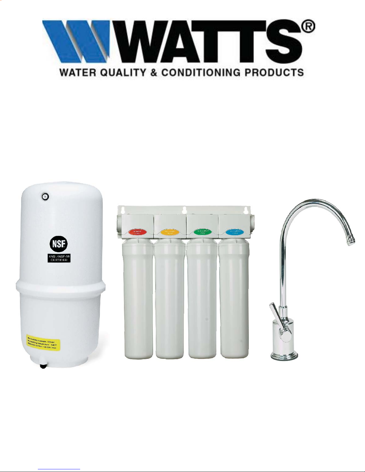
Thank you for your purchase of a state of the art Watts Reverse Osmosis (RO) water treatment system. Water quality
concerns are becoming more of a focus for the public. This Watts water treatment system has been designed and tested to
provide you with high quality water for years to come. The following is a brief overview of the system.
Your Reverse Osmosis System:
Osmosis is the process of water passing through a semi permeable membrane in order to balance the concentration of
contaminants on each side of the membrane. A semi permeable membrane is a barrier that will pass some substances like
clean water, but not other substances such as salts and minerals.
Reverse osmosis uses a semi permeable membrane; however, by applying pressure across the membrane, it concentrates
contaminants on one side of the membrane, producing clean water on the other. This is why RO systems produce both clean
drinking water and waste water that is fl ushed from the system.
Your system is a Four Stage RO which is based upon four separate treatment segments within one complete water fi ltration
system. These stages are as follows:
Stage 1 – Sediment fi lter, recommended change 6 months.
The fi rst stage of your RO system is a fi ve micron sediment fi lter that traps sediment and other particulate matter
like dirt, silt and rust which affect the taste and appearance of your water.
Stage 2 – Pre-Carbon fi lter, recommended change 6 months.
The second stage contains a carbon block fi lter. This helps ensure that chlorine and other materials that cause bad
taste and odor are greatly reduced.
Stage 3- Membrane, recommended change 1-2 years.
Stage three is the heart of the reverse osmosis system, the RO membrane. This semi-permeable membrane will take
out salts, minerals, metals, bacteria, virsus, cysts, and much more. Because the process of extracting this high quality
drinking water takes time, your RO water treatment system is equipped with a storage tank.
Stage 4- Post Carbon Filter, recommend change 12 months.
The post carbon fi lter is a granular activated carbon (GAC) cartridge using coconut shell carbon. This fi lter
provides fi nal polishing and assures good tasting drinking water.
System Maintenance
Just because you can not taste it, does not mean that it is not there. Contaminants such as lead, chromium, VOC’s and arsenic
are undetectable to the taste. Additionally, over time if you do not replace the fi lter elements, other bad tastes and odors will
be apparent in your drinking water.
This is why it is important to change out your fi lter at the recommended intervals as indicated in this system manual. Should
you have any further questions please contact the dealer that you purchased the unit from.
Page 2
Page 3

With proper installation and maintenance, this system will provide you with high quality water for years
to come. All of Watts water enhancement products are rigorously tested.
Operational Parameters ........................................................................................................................ 4
Table of Contents
Contents of Reverse Osmosis System .................................................................................................. 4
Tools Recommended For Installation .................................................................................................... 4
Drill a Hole for the Faucet in a Porcelain Sink ....................................................................................... 5
Punch a Hole for the Faucet in a Stainless Steel Sink ..........................................................................5
Faucet Installation ................................................................................................................................. 6
Adapta Valve Installation ...................................................................................................................... 7
Reverse Osmosis Module Mounting...................................................................................................... 7
Air Gap/Non Air Gap Installation............................................................................................................ 8
Drain Saddle Installation........................................................................................................................ 9
Tank Valve Installation ........................................................................................................................... 9
White Tube Connection ....................................................................................................................... 10
3/8” Black Tube Connection........................................................................................... ......................11
How to Use Quick Connect Fittings ......................................................................................................11
Red Tube Connection (From Faucet) .................................................................................................. 12
Blue Tube Connection (From Faucet) ................................................................................................. 12
Start Up Instructions ............................................................................................................................ 12
Cartridge Replacement........................................................................................................................ 13
Annual Maintenance ........................................................................................................................... 14
Procedure for Extended Non-Use ....................................................................................................... 15
Trouble Shooting ................................................................................................................................. 16
Service Record .................................................................................................................................... 17
Warranty Information ........................................................................................................................... 18
Unit Drawing ...................................................................................................................................... 19
Page 3
Page 4
Operational Parameters
Operating Temperatures: Maximum 100°F (37.8°C) Minimum 40°F (4.4°C)
2
Operating Pressure: Maximum 85 psi (6.0 kg/cm
pH Parameters: Maximum 11 Minimum 2
Iron: Maximum 0.2 ppm
) Minimum 40 psi (2.80 kg/cm
2
)
TDS (Total Dissolved Solids) < 1800 ppm
Turbidity < 5 NTU
Hardness: Recommended hardness should not exceed 10 grains per gallon, or 170 ppm. System
will operate with hardness over 10 grains but the membrane life may be shortened. (Addition of a
water softener may lengthen the membrane life.)
Note: The operating pressure in your home should be tested over a 24 hour period to attain the
maximum pressure. If incoming pressure is above 85 psi a pressure regulator is recommended and
if over 100 psi then a pressure regulator is required.
Note: Reverse Osmosis water should not be run through copper tubing as the purity of the water
will leach copper and cause an objectionable taste in water and may cause damage to copper
tubing. Watts supplies specialty medias that can be used if copper tubing is down stream of
the RO. Be sure to follow any state or local regulations.
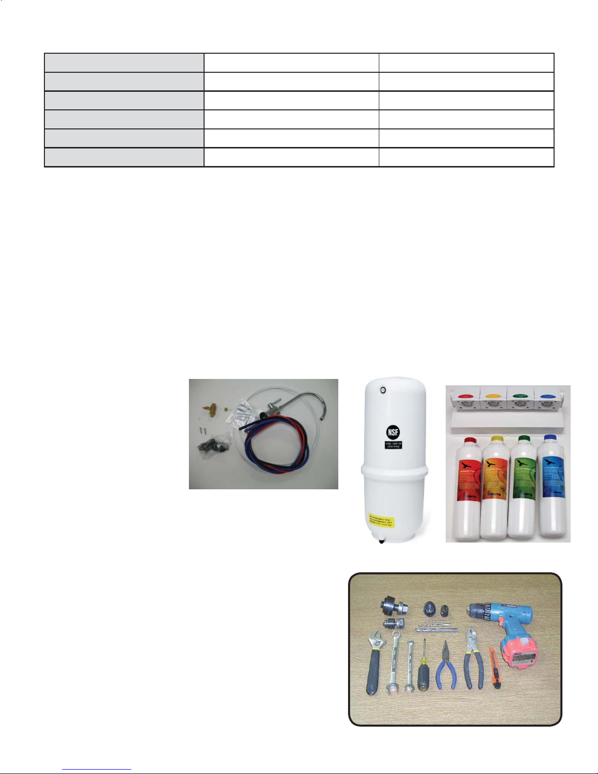
Contents of Reverse Osmosis (RO) System
1 Tank
1 RO System
1 Parts Bag
1 Faucet Bag
1 Manual and Warranty Card
If any of the items are missing please contact your
dealer.
Tools Recommended For Installation
1 1/4” Hole Saw Bit for Faucet opening and/ or
Round Knock out Punch for Stainless Sinks 1 1/4”
Adjustable Wrench
Sharp Knife
1/2”- 13/16” Open End Wrenches
Phillips Screw Driver
Needle Nose Pliers- Adjustable Pliers
Electric Drill
Page 4
Page 5
Drill a Hole for the Faucet in a Porcelain Sink
Note:
Some sinks are predrilled with 1 ½” or 1 ¼” diameter hole that you can use for your
RO faucet. (If you are already using it for a sprayer or soap dispenser, see step 1).
Porcelain sinks are extremely hard and can crack or chip easily. Use extreme caution
when drilling. Watts accepts no responsibility for damage resulting from the installation of
faucet.
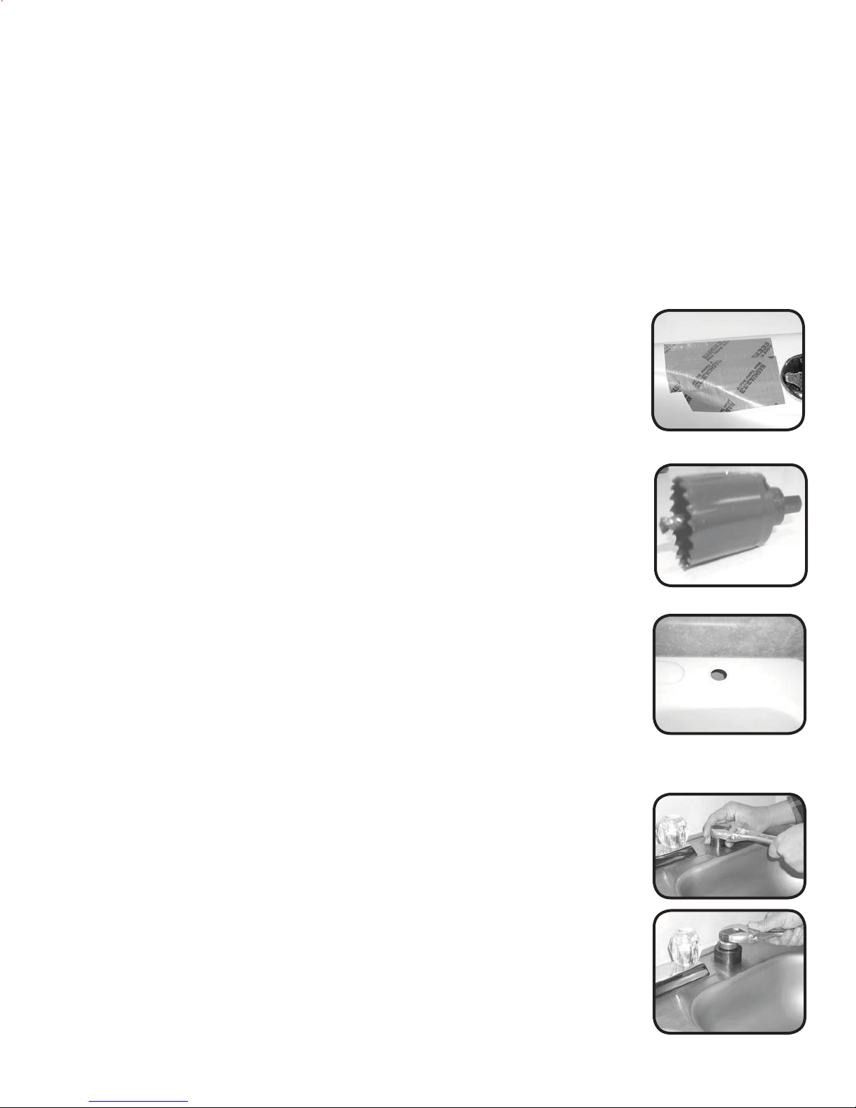
Step 1
Determine desired location for the faucet on your sink and place a piece
of masking tape on location where the hole is to be drilled. Mark the
center of the hole on the tape.
Step 2
Using a variable speed drill on the slowest speed, drill a 1/8“ pilot hole
through both porcelain and metal casing of sink at the center of the
desired location. (If drill bit gets hot it may cause the porcelain to crack
or chip), use lubricating oil or liquid soap to keep cool.
Step 3
Using a 1 ¼” hole saw, proceed to drill the large hole. Keep drill speed
on the slowest speed and use lubricating oil or liquid soap to keep the
hole saw cool during cutting.
Step 4
Make sure the surroundings of the sink are cooled before mounting the
faucet to the sink after drilling. Remove all sharp edges.
Punch a Hole for the Faucet in a Stainless Steel Sink
Note:
Step 5
If mounting faucet to a Stainless Steel Sink you will need a 1 ¼” Hole
Punch. The faucet opening should be centered between the back
splash and the edge of the sink, ideally on the same side as the vertical
drain pipe.
Drill a ¼” pilot hole. Use a 1/2” Hole Punch and an adjustable wrench to
punch the hole in the sink. Change to the 1 ¼” Hole Punch to enlarge
the hole.
The faucet can now be installed.
Page 5
Page 6
WATTS Chrome
(Top Mount) Faucet Installation
Watts Top Mount Faucet
Minimum Maximum
Mounting Hole Size 1.00” 1.25”
Torque on Toggle Bolt 5lb.in. (max)
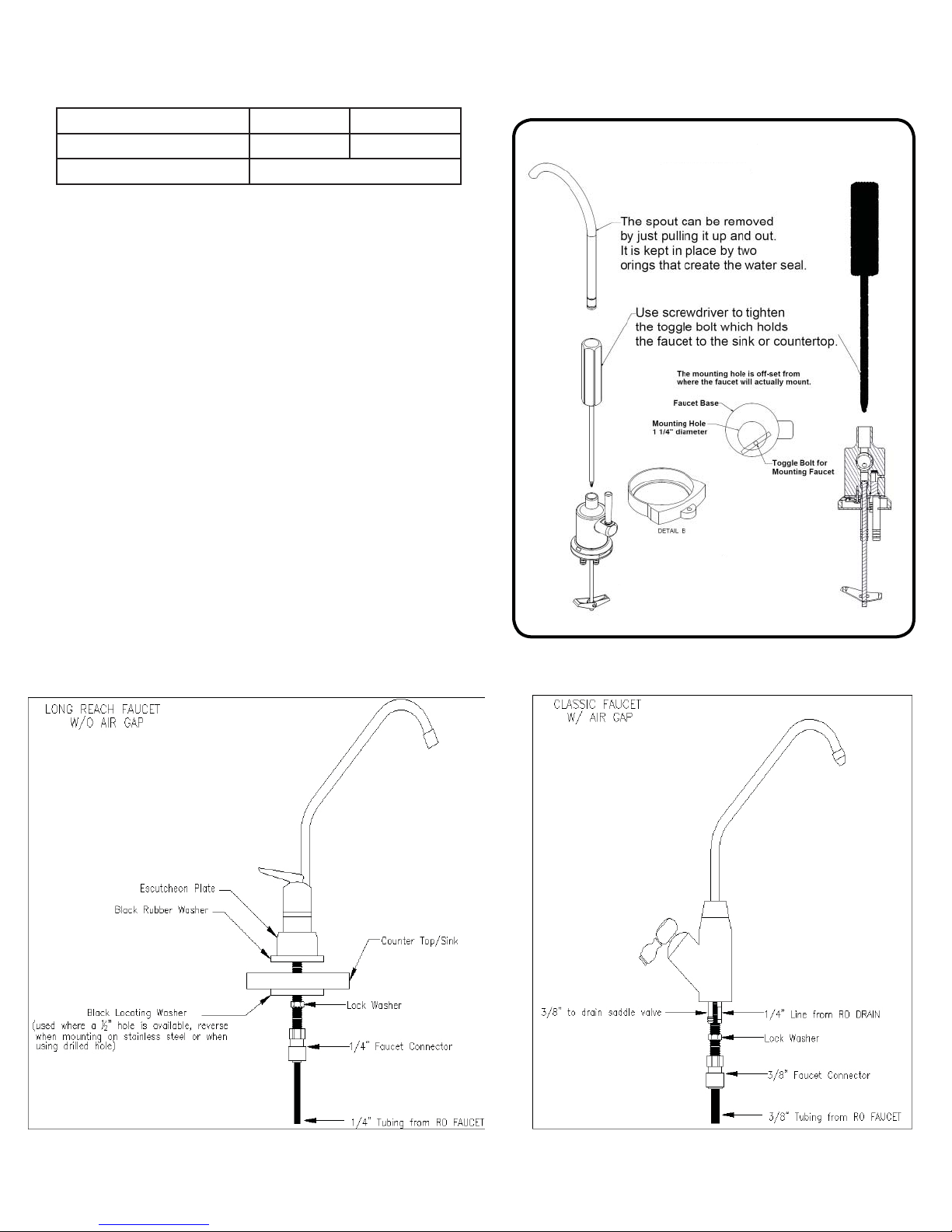
Step 6
Step 7
Step 8
Gather and identify the faucet pieces.
Remove faucet base & faucet spout from their respective
plastic bags. From above the sink, feed the faucet tubing &
toggle bolt down through the 1¼” mounting hole in the sink.
Ensure that the soft rubber gasket is uniformly positioned in
between the base and the top of the sink.
Align the faucet base so that the handle is on the right side and
the base is sitting fl ush on the sink top. Turn the handle down
(towards you) to the “ON” position to reveal the tightening
screw (located where the spout will be inserted). Using a
phillips head screwdriver, turn the screw clockwise until the
toggle bolt secures the faucet base snug onto the sink top,
do not over torque toggle bolt (5lb. in. max)
Once the faucet base is securely fastened to the sink top,
insert the faucet spout into the faucet base until it is fully
seated. Turn the handle up (away from you) to the “OFF”
position.
Step 9
Completion of faucet installation (tubing connections) will be
done later in this manual. Refer to the Black Tube Connection
(page 10), Red Tube Connection (page 11), and Blue Tube
Connection (page 11) sections of this manual.
Other Faucet Style Installation
Page 6
Page 7
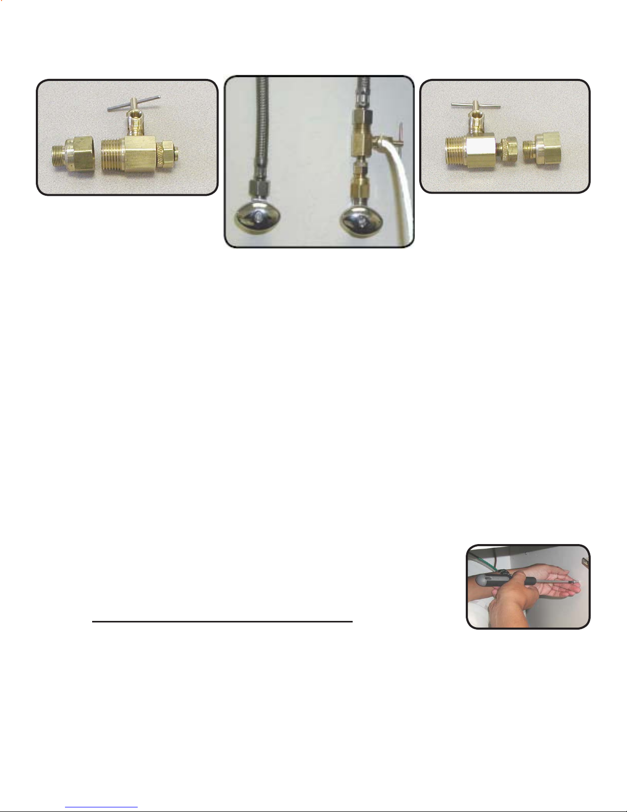
Adapta Valve Installation
Confi guration for 3/8”
compression fi ttings
Confi guration for 1/2”
compression fi ttings
Hot
Supply
Cold
Supply
Step 10
Locate the cold water supply under the sink.
Turn off the cold water supply to the faucet by turning the angle stop valve completely off.Step 11
Step 12 Attach adapta valve as illustrated in the three photos above, choosing the confi guration that
fi ts your plumbing. (When attaching the adapta valve to straight pipe threads, use Tefl on
tape on the threads). The white tube from inlet side of RO module will be cut to length and
attached later in the installation.
Caution: Water supply line to the system must be from the cold water supply line only. Hot
water will severely damage your system.
Reverse Osmosis Module Mounting
Step 13 Determine best location for the RO module to be mounted to allow
for future system maintenance. The parts bag has 2 self tapping
screws. Using a Phillips screwdriver, screw them into the cabinet
wall 10 1/2” apart and 16” from the bottom of the cabinet.
Do not cut any RO system tubes at this time.Note:
Page 7
Page 8
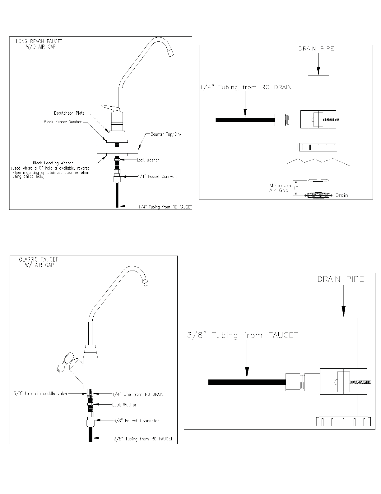
Non Air Gap Faucet Installation
Air Gap Faucet Installation
Page 8
Page 9
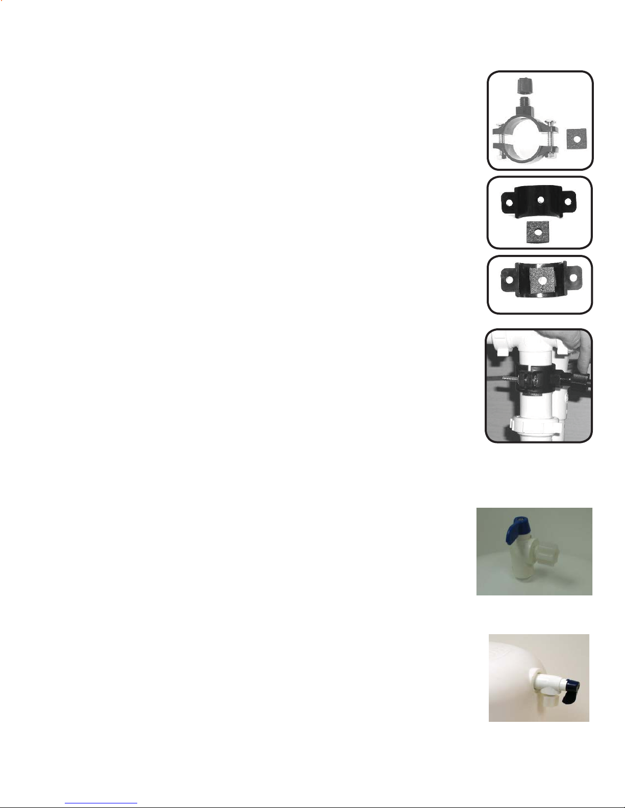
Drain Saddle Installation
Drain Saddle fi ts standard 1 ¼” – 1 ½” drain pipes
Caution:
Step 14
If you have a garbage disposal, do not install the drain line near it. Installation
of the drain line must be either above the disposal, or if a second sink drain is
available, install it above the cross bar on the second sink. Installation of the
drain line near a garbage disposal may cause the drain line to plug.
Gather the pieces of the drain saddle
1 Black compression nut 1 Semicircle bracket with opening
2 Screws 1 Foam washer
2 Nuts for screws 1 Semicircle bracket
1 3/8 or 1/4” Tube Insert
Step 15
The small square black foam gasket with a circle cut out of the middle
must be applied to the inside of the drain saddle. Remove sticky tape
backing and stick to the drain saddle as shown.
Step 16 Drill a ¼” hole through the drain pipe at least 1 1/2” above the nut
of the P-trap to allow for the removal of the P-trap if necessary.
Assemble the drain saddle around the drain pipe. Position the drain
saddle over the drilled hole in pipe. Insert screw driver into the
opening of the drain saddle and align with drilled hole in drain pipe.
Using Phillips screw driver tighten screws evenly and securely on
both sides of the drain saddle. Attach black compression nut, but
do not tighten at this time. The black tubing will be installed later.
Caution:
Do not over tighten the screws. It may crack the drain saddle.
Tank Valve Installation - (Metal Tanks)
Step 17
*Note:
Step 18
Wrap 3 to 4 turns of Tefl on tape clockwise around the male pipe threads
coming out of the top of the tank.
Do not let the tape cover the opening
in the fi tting.
Thread the plastic valve onto the tank fi tting. Do not over tighten
or the valve could crack.
Tank Valve Installation - (Plastics Tanks)
Step 17
Step 18 Thread the plastic valve onto the tank fi tting. Do not over tighten or
Make sure the O-Ring is located at the bottom of recess for the tank
connection.
the valve could crack.
Page 9
Page 10
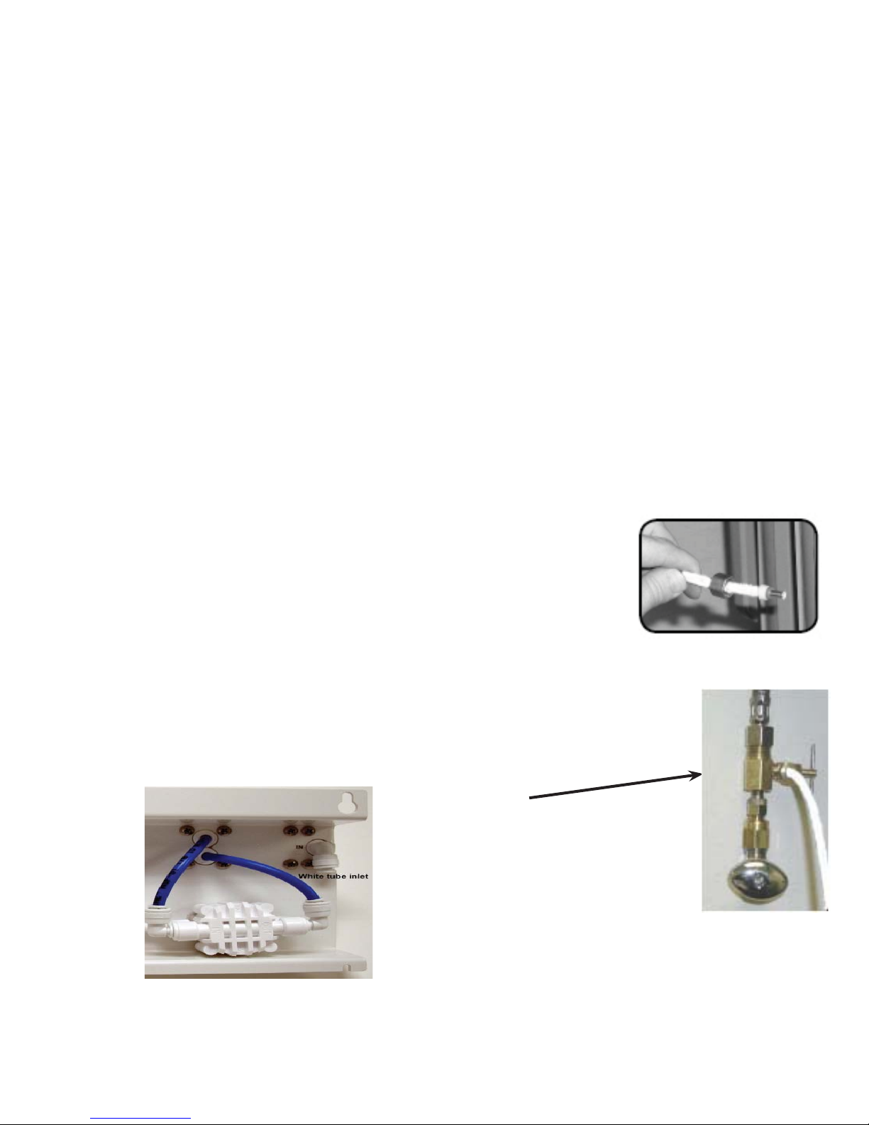
White Tube Connection
Note: The white tube will be cut into two pieces. One for the
inlet and one for the tank.
Connect White Tube from TANK Port on RO Module to the Tank
Step 19
Position tank in desired location. Stand it upright or lay it on its
side (using the black plastic stand). Measure the white tube from
the RO module port marked TANK over to the tank and cut it to
desired length.
Step 20
Insert the white 1/4” tube through tank valve compression nut.
Place 1/4” plastic insert in tubing. Push tubing into valve. Hand
tighten the compression nut securely, and add 1/4 turn with a
wrench.
Connect White Tube from Adapta Valve to IN Port on RO
module
Step 21
Remove a brass nut, plastic sleeve and brass insert from the parts
bag. Place nut on the tube fi rst, then the sleeve (Small taper end
of sleeve must point to the end of tube) and then insert the brass
insert into the end of the tube.
Step 22
Insert the white tube into the ¼” opening on the adapta valve until
it stops. Slide nut and sleeve down and thread onto the male pipe
threads. Use a ½” wrench to securely tighten. Run the tube to
the inlet on the back of the RO system. Leave enough tube so it
is not kinked and cut the tube to desired length.
Adapta Valve
Page 10
Page 11
3/8” Black Tube Connection from Faucet
Note:
The tubing must be as SHORT and STRAIGHT as possible
to the drain saddle, making a downward slope from faucet
to drain saddle to allow for proper drainage.
Step 23
Step 24
Measure the black tube from faucet to the black drain saddle and
make a straight cut through tube.
Remove black plastic nut from drain saddle. Slip black tube
through black nut. Press the plastic insert into the end of the
tube. Insert black tube into the opening in the drain saddle and
Note:
How To Use the Quick Connect Fittings on the RO Module
hand tighten the black nut, and add 1/4 turn with a wrench.
This is a gravity feed line, if there is any bend or dip in the
tube the rinse water will not fl ow into the drain properly.
Water may back up and come out of the air gap hole in the
back of the faucet base.
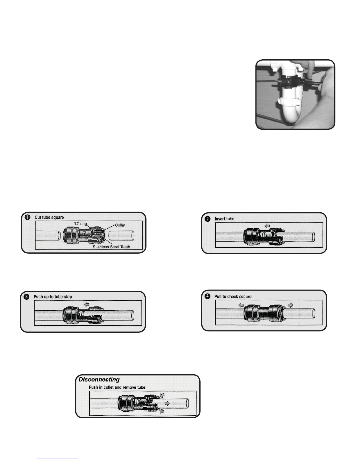
To make a connection, the tube is simply pushed into the fi tting.
It is essential that the outside diameter be free of score
marks and that burrs and sharp edges be removed before
inserting into fi tting.
Push the tube into the fi tting, to the tube stop. The collet
(gripper) has stainless steel teeth which hold the tube
fi rmly in position while the O-ring provides a permanent
leak proof seal.
Fitting grips before it seals. Ensure tube is pushed into
the tube stop.
Pull on the tube to check that it is secure. It is a good practice
to test the system prior to leaving site and /or before use.
To disconnect, ensure the system is depressurized before
removing the tube. Push in collect squarely against face
of fi tting. With the collet held in this position, the tube can
be removed. The fi tting can then be reused.
Page 11
Page 12
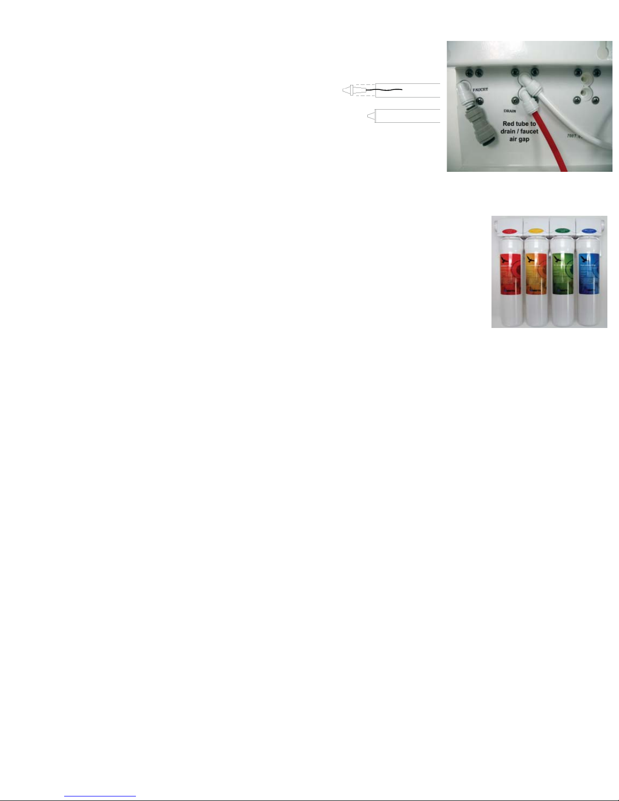
Connect the Red Tube from Faucet to RO Module
Step 25
a) Insert the fl ow control into the end of the red
tubing coming from the faucet.
b) Insert the end of red tubing into the fi tting
labeled “Drain” on the back of the unit.
Connect the Blue Tube from the Faucet to RO Module
Step 26
Insert the blue 3/8” tube from the faucet into the port on the system
marked “FAUCET”. Make sure the tube is pushed in all the way
to the tube stop.
Install the Cartridges
Step 27
Identify each cartridge and the proper location on the system by
matching the colors and description.
Step 28
Insert each cartridge with a 1/4 turn in the clock wise direction. The cartridge
is installed properly when the label is facing toward the front of the unit.
Note: The cartridge head swivel up and down for easy access.
Start up Instructions
Step 1
Turn on the incoming cold water at the angle stop valve. Open the needle valve on the brass
Adapta Valve by turning counter clockwise. Check the system for leaks and tighten any fi tting
as necessary. (Check frequently over the next 24 hours to ensure no leaks are present).
Step 2
Step 3
Step 4
Step 5
NOTE:
If system is connected to an ice maker, turn the ice maker off (or do not allow water to fl ow to
the ice maker) until Step 5 “fl ushing” is complete and the tank has been allowed to completely
fi ll. Connection from the RO to the ice maker system should have an in-line valve installed
before the ice maker so it can easily be closed to prevent water fl owing to the ice maker
during start up and periodic maintenance. Your RO tank must be allowed to fi ll up in order
for the ice maker system to work properly. (If you are installing an ice maker kit from Watts,
tee off of the blue line between RO system and faucet).
Open the RO faucet and leave it open until water begins to trickle out, (it will come out
slowly).
After water trickles out of the faucet, close the faucet so the tank will fi ll with water. The tank
will take 6 to 10 hours to fi ll completely depending on the production capability of the mem-
brane, local water temperature and pressure.
After the Tank has fi lled, open the faucet to fl ush the tank completely to remove carbon particles
from fi nal fi lter. Repeat this step two more times. The fourth tank can be used for drinking.
*Note: The fl ushing of the tank 3 times is only necessary during initial installation.
This should take about a day to complete.
This reverse osmosis system contains replaceable components critical to the effi ciency of
the system. Replacement of the reverse osmosis component should be with one of identical
specifi cations, as defi ned by the manufacturer, to assure the same effi ciency and contaminant
reduction performance. Periodic inspection and following proper system maintenance is critical
for continued performance.
Page 12
Page 13
Cartridge Replacement
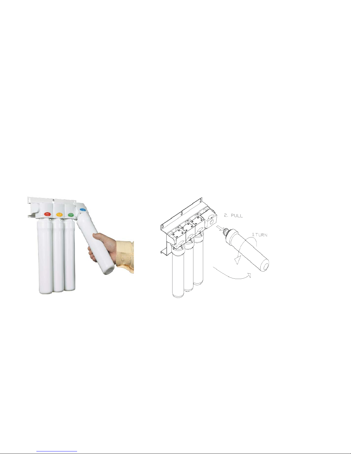
Cartridge replacement is made easy with the Watts Kwik Change system. The cartridge heads contain
built in check valves and shutoff valves so that the cartridges can be changed without shutting off the
water supply or the storage tank. The head are also hinged to allow easy access to the cartridges.
The following steps should be followed to change the cartridges.
Note: A small amount of water may be released when changing cartridges.
Step 1
Step 2
Step 3
Step 4
Step 5
Step 6
Grasp the cartridge and pull it towards you.
Rotate the cartridge 1/4 turn counter clockwise.
Remove the cartridge and dispose of it.
Remove the protective cap from the new cartridge.
Orient the cartridge with the label facing to the left (9 o’clock
position).
Push the cartridge into the head and rotate it clock wise 1/4 turn.
Step 7
Step 8 Wipe up any spill water.
Return the cartridge to the vertical position.
The Sediment cartridge, and pre carbon cartridge should be changed
every six months.
The RO membrane cartridge should be changed every one or two
years.
The post carbon cartridge should be changed once a year.
Page 13
Page 14

Annual Maintenance
Storage Tank Sanitization
Turn off the incoming water supply at the adapta valve.
Open the faucet, allow the tank to empty, and then close the faucet.
Remove the tubing between the tank and the RO unit.
Drain the water from the tubing and pour one teaspoon of household bleach into the tubing.
Reinstall the tubing between the tank and the RO unit.
Turn on the water supply at the adapta valve.
Allow the RO unit to fi ll the tank overnight.
Open the faucet and allow the tank to empty, and then close the faucet.
Replace the post carbon fi lter cartridge.
Step 1
Step 2
Step 3
Step 4
Step 5
Step 6
Step 7
Step 8
Step 9
Drain line fl ow restrictor
Step 1
Step 2
Step 3
Step 4
Step 5
Step 6
Turn off the incoming water supply at the adapta valve.
Remove the red tubing from the back of the RO unit.
Remove and inspect the orifi ce in the fl ow restrictor. Clean if necessary.
Reinstall the fl ow restrictor into the end of the red tubing.
Reinstall the red tubing onto the back of the RO unit.
Turn on the water supply at the adapta valve.
Page 14
Page 15
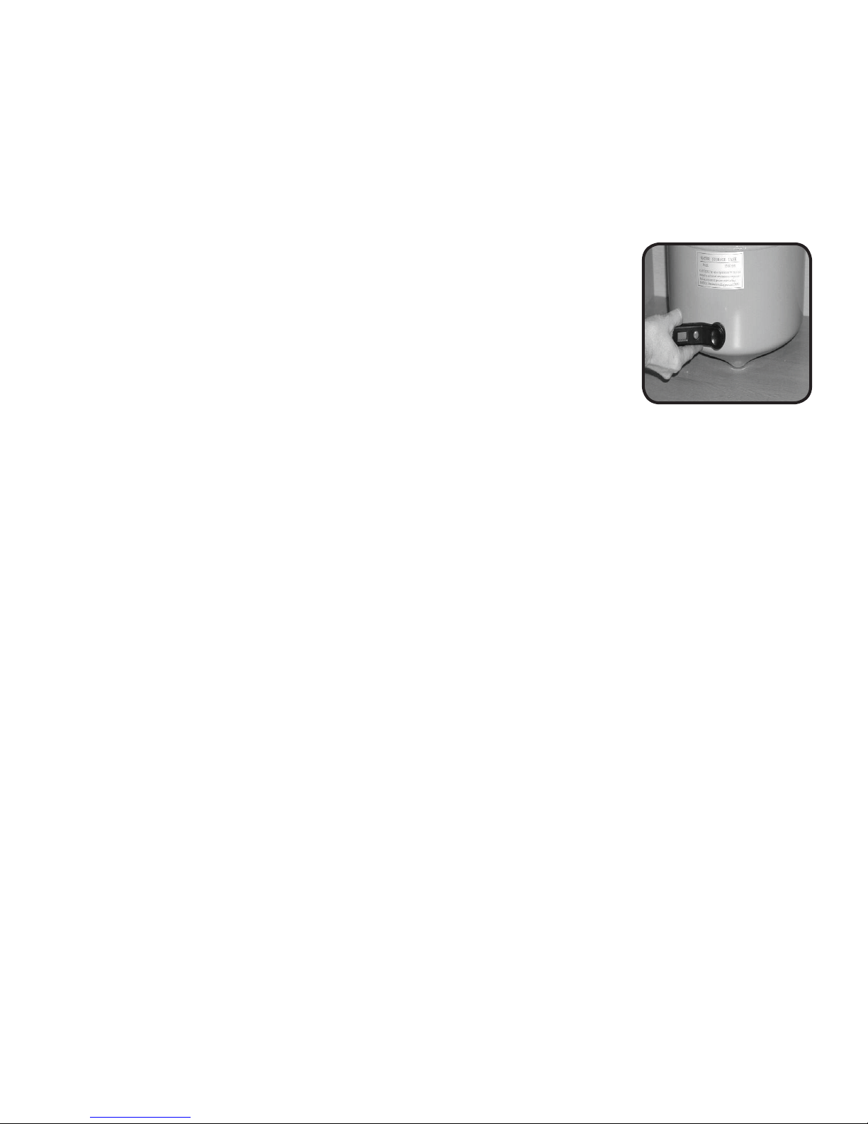
Tank air pressure
Step 1
Step 2
Step 3
Step 4
Step 5
Turn off the incoming water supply at the adapta valve.
Open the faucet, allow the tank to empty, and then close the faucet
Check the pressure in the tank using a tire pressure gauge on the air valve.
The tank pressure should be between 5-7 psi. Use a bicycle pump to add air if necessary.
Turn on the water supply at the adapta valve.
Procedure for Extended Non-Use
If the system will not be used for an extended period (more than 2 months) perform the
following.
Step 1
Step 2
Step 3
Step 4
Turn off the incoming water supply at the adapta valve.
Open the faucet, allow the tank to empty, and then close the faucet.
Remove and discard the sediment fi lter, pre carbon fi lter, and post carbon fi lter cartridges.
Remove the RO membrane cartridge. Place it in a zip lock bag and store it in the refrigerator.
Step 5
To begin using the unit again, follow the startup and tank sanitization procedures.
Page 15
Page 16

TROUBLE SHOOTING
Problem Cause Solution
1. Low/Slow Production Low Water Pressure Assure a minimum of 40 psi incoming water pressure.
Watts sells a booster pump if home water pressure is
low. Make sure water supply is turned on and Adapta
Valve is all the way open.
Crimps in tubing Check tubing and straighten or replace as necessary.
Clogged pre-fi lters Replace pre-fi lters.
Fouled membrane Replace membrane and clean fl ow restrictor.
Tank valve closed Open valve on storage tank
2. Milky colored Water Air in system Air in the system is a normal occurrence with initial start
up of the RO system. This milky look will disappear
during normal use within 1-2 weeks. If condition reoccurs
after fi lter change, drain tank 1 to 2 times.
3. Water constantly Low water pressure See #1 Above
running/unit will not
shut off Fouled membrane Replace membrane
High water pressure Check incoming water pressure to make sure it does not
exceed 100psi. A pressure relief valve may be necessary.
High air pressure in tank Empty storage tank of water. Set tank air pressure to 5
psi. See Page 15.
4. Noise from faucet or drain Air gap faucet Inherent sound with air-gap faucets.
Location of drain saddle See diagram for proper location of drain saddle.
Higher capacity membrane Normal with high capacity membrane
High water pressure Check incoming water pressure to make sure it does not
exceed 100psi. A presser relief valve may be necessary.
5. Faucet leaks from Crimp or loop in drain line Straighten black 3/8 drain tube. Cut off any excess tubing
the air gap feature Drain tube clogged/restricted Caused from dishwasher or garbage disposal.
Disconnect the 3/8” black tube at the drain, clean the 3/8”
black tube out with a wire, then reconnect.
6. Small amount of water in System just starting up Normally it takes 6-10 hours to fi ll tank. Note: Low
storage tank pressure and/or temperature can drastically reduce
production rate.
Low water pressure See #1 Above
Too much air in tank Add air if below 5 psi and bleed if above 5 psi. Check
only when tank is empty of water. See Page 15.
7. Water leaks from the Not properly tightened. Tighten the bowl
fi lter housing Missing or kinked O-ring Turn off the water supply. Release the pressure, remove
bowl and replace the O-ring. (p/n 113043). Make sure
the O-ring is seated in the fi lter bowl properly before
reinstalling the fi lter bowl.
Page 16
Page 17
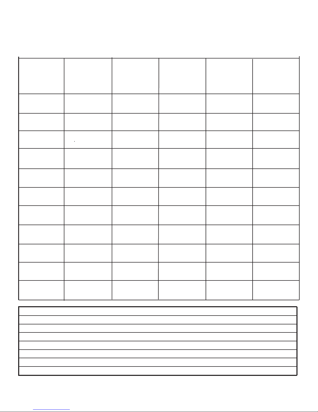
Service Record
Serial No. _____________________
Date of Purchase:__________ Date of Install:___________ Installed by:__________________
Date
1st stage
Sediment
(6 months)
2nd stage
Carbon
(6 months)
4th stage
Carbon
(1 year)
3rd stage
Membrane
(2-5 years)
NOTES:
Page 17
Page 18

Limited Warranty
This Reverse Osmosis System is warranted against defects in material and workmanship for a period of one year from the
date of installation, not to exceed 2 years from the date of manufacture. Expendable items such as fi lter cartridges and
membranes are not covered by this warranty.
How to obtain Warranty Service: Contact the dealer that you purchased the system from. Watts will work in conjunction
with our dealer to repair or replace at our discretion any unit that is determined to be defective. No returns will be accepted with out the proper return authorization number.
What this warranty does not cover: This warranty does not cover defects resulting from improper installation, from abuse,
misuse, misapplication, improper maintenance, neglect, alteration, accidents, casualties, fi re, fl ood, freezing, environmen-
tal factors, water pressure spikes or other such acts of God.
Return shipping charges are not included in this warranty and are the responsibility of the end user.
This warranty will be void if defects occur due to failure to observe the following conditions:
1. The Reverse Osmosis System must be hooked up to a potable municipal or well cold water supply.
2. The hardness of the water should not exceed 10 grains per gallon, or 170 ppm.
3. Maximum incoming iron must be less than 0.2 ppm.
4. The pH of the water must not be lower than 2 or higher than 11
5. The incoming water pressure must be between 40 and 100 pounds per square inch.
6. Incoming water to the RO cannot exceed 105 degrees F (40 degrees C.)
7. Incoming TDS/Total Dissolved Solids not to exceed 1000 ppm.
8. Do not use with water that is microbiologically unsafe or of unknown quality without adequate disinfection before
or after the system.
This warranty does not cover any equipment that is relocated from the site of its original installation.
This warranty does not cover any equipment that is installed or used outside the United States of America and Canada.
This Reverse Osmosis System
Limited Warranty
is warranted against defects
LIMITATIONS AND EXCLUSIONS:
in material and workmanship
for a period of one year for the
WATTS WILL NOT BE RESPONSIBLE FOR ANY IMPLIED WARRANTIES, INCLUDING THOSE OF MERCHANTABILITY AND FITNESS FOR A PARTICULAR PURPOSE. WATTS WILL NOT BE RESPONSIBLE FOR
ANY INCIDENTAL OR CONSEQUENTIAL DAMAGES, INCLUDING WATER DAMAGE, TRAVEL EXPENSE,
TELEPHONE CHARGES, LOSS OF REVENUE, LOSS OF TIME, INCONVENIENCE, LOSS OF USE OF THE
date of purchase. Expendable
items such as fi lter cartridges
and membranes are not cov-
ered by this warranty.
EQUIPMENT, AND DAMAGE CAUSED BY THIS EQUIPMENT AND ITS FAILURE TO FUNCTION PROPERLY.
THIS WARRANTY SETS FORTH ALL OF WATTS RESPONSIBILITIES REGARDING THIS EQUIPMENT.
OTHER CONDITIONS:
If Watts chooses to replace the equipment, it may be replace with reconditioned equipment. Parts used in repairing or
replacing the equipment will be warranted for 90 days from the date the equipment is returned to you or for the remainder
of the original warranty period, whichever is longer. This warranty is not assignable or transferable.
Page 18
Page 19
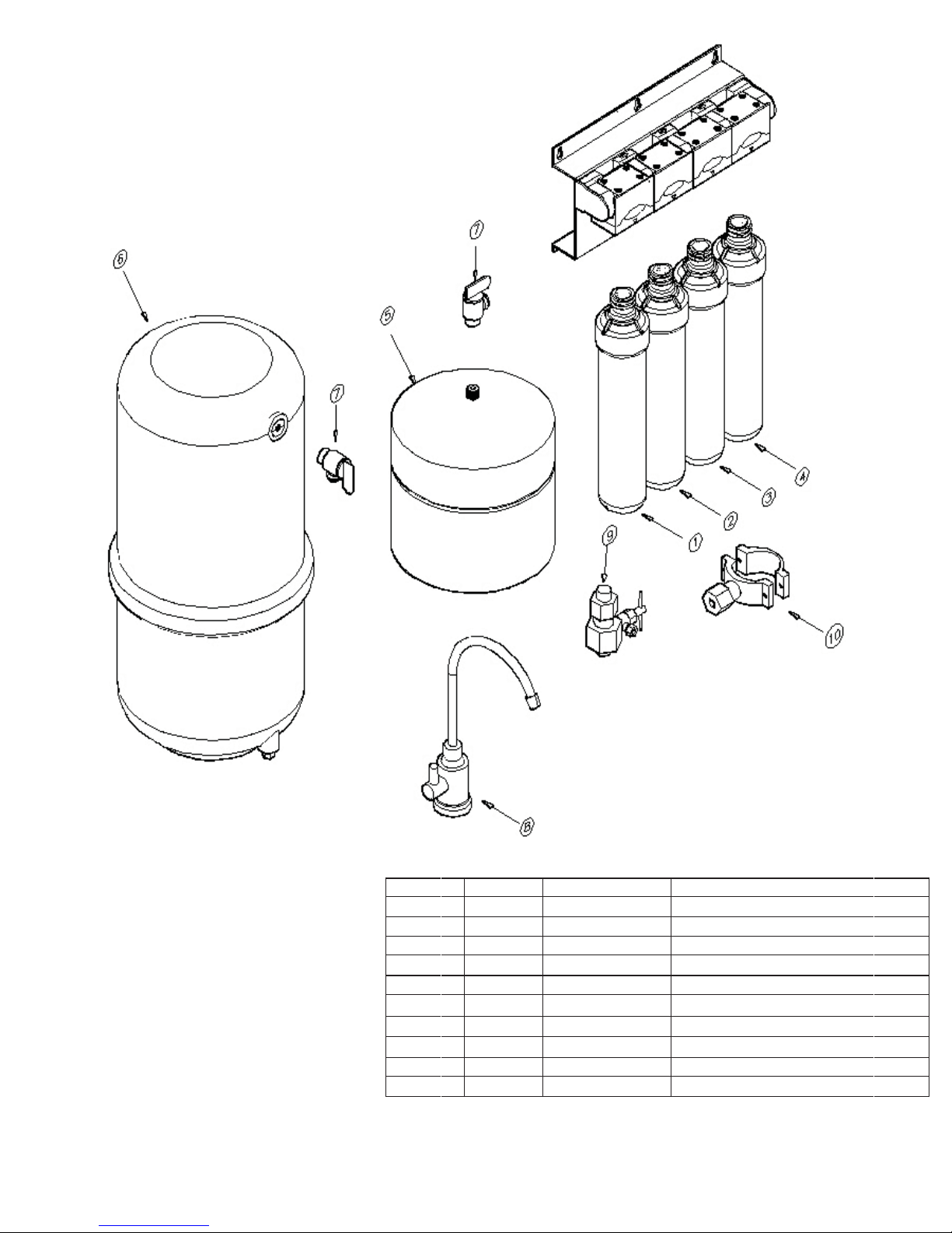
ITEM QTY PART # DESCRIPTION
1 1 WQCS-10,11,13” SEDIMENT FILTER
2 1 WQCC-10,11,13” PRE-CARBON FILTER
3 1 WQCM-10,11,13” MEMBRANE FILTER(50 OR 100 GPD)
4 1 WQGAC-10,11,13” POST CARBON FILTER
5 1 FRO-132-WH 4 GALLON WHITE STEEL TANK
6 1 ROPRO4-W RO ROPRO STORAGE TANK, WHITE PLASITC
7 1 BV9014W 3/8” FEMALE ELBOW SHUT-OFF
8 1 F116000 FCT TOP MOUNT CHROME, AIRGAP FAUCET
9 1 F134007 RO ADAPT-A-VALVE
10 1 SC500B38 DRAIN SADDLE 3/8”
Page 19
Page 20

Page 20
 Loading...