

Page 1
Installation, Operation
and Maintenance Manual
Model PWPERMKIT
PERMEATE PUMP INSTALLATION MANUAL
PURE WATER
Important
Please read the entire manual before proceeding with the
installation and startup. Your failure to follow any attached
instructions or operating parameters may lead to the product’s
failure.
Save manual for future reference.
IOM-WQ-PWPERMKIT
PWPERMKIT
Table of Contents Pages
Package Contents.......................................2
How to Use the Quick-Connect Fittings on the RO Module ........2
Permeate Pump Installation with the Standard System ...........3
Permeate Pump Installation with the Manifold System .......... 4-5
Permeate Pump Installation with the KWIK-CHANGE RO ....... 6-7
Limited Warranty ........................................8
Do not use with water that is microbiologically unsafe or
Note:
of unknown quality without adequate disinfection before or after
the system.
Page 2
Introduction
For maximum performance and reliability, please follow the simple
instructions in this manual.
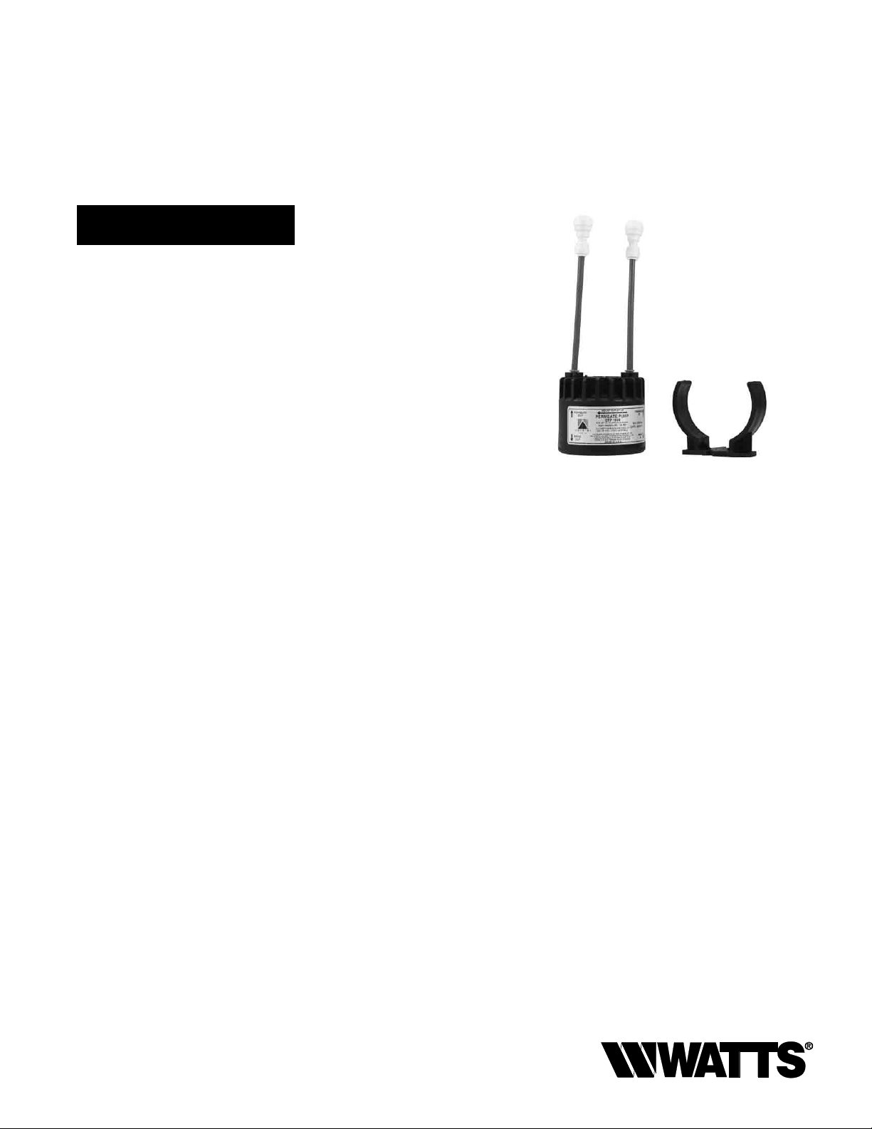
Package Contents
Examine the components carefully to make sure no damage has
occurred to the Permeate Pump. Care should be taken to ensure
the pump is not dropped or mishandled; dropping will damage the
pump.
Package contains the following:
• (1) Permeate Pump with mounting clip
• (2) Quick-Connect Reducer Union
• (2) 3" long,
• (1) 48" long,
3
• (1)
1
• (1)
3
• (1)
1
• (1)
1
⁄4" Blue tubes
1
⁄4" Blue tube
⁄8" Quick-Connect Union Tee
⁄4" Quick-Connect Union Tee
⁄8" Plug Insert
⁄4" Plug Insert
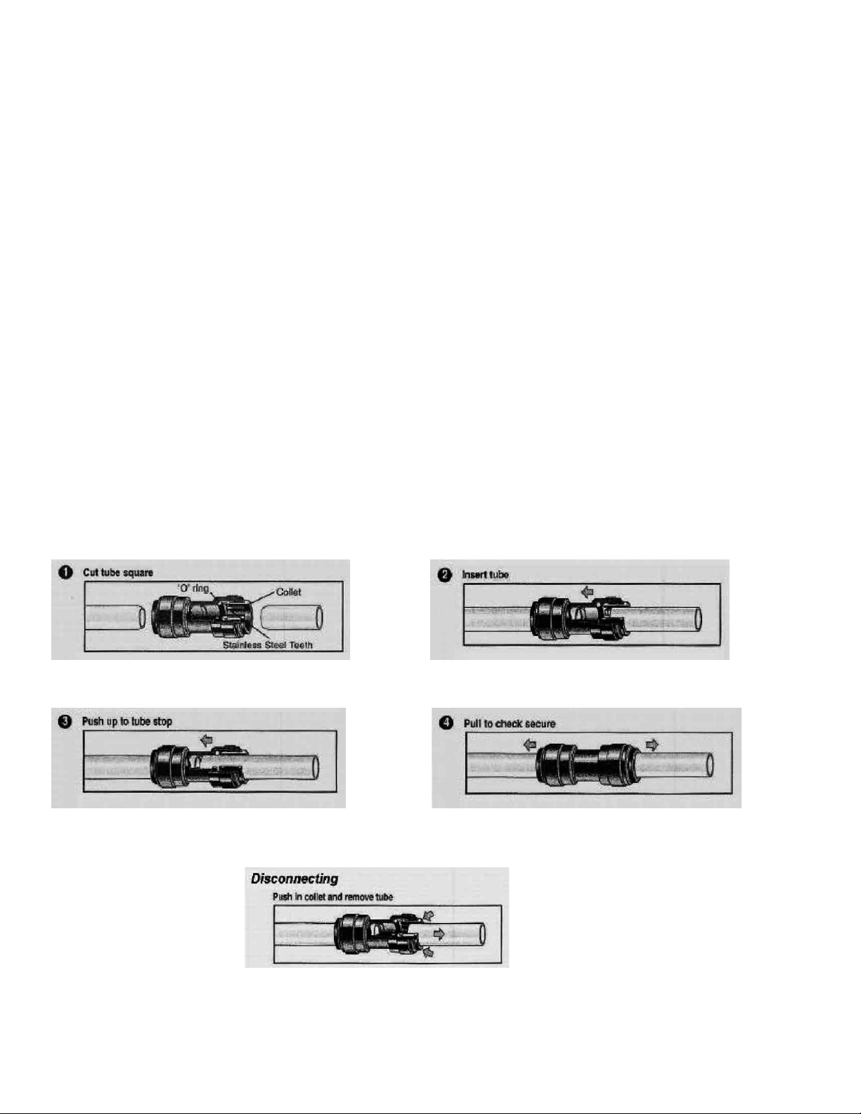
How to use the Quick-Connect fittings on the RO Module
To make a connection, the tube is simply pushed into the fitting.
Place a piece of tape
1
⁄2" from end of tube to indicate how far the
tube should be inserted. The unique Watts Quick-Connect locking
Cut the tube square. It is essential that the outside diameter be free of score marks
and that burrs and sharp edges be removed before inserting into fitting.
Push the tube into the fitting, to the tube stop. The collet (gripper) has stainless
steel teeth which hold the tube firmly in position while the O-ring provides a permanent leak proof seal.
system holds the tube firmly in place without deforming it or restricting flow.
Fitting grips before it seals. Ensure tube is pushed into the tube stop.
Pull on the tube to check that it is secure. It is a good practice to test the system
prior to leaving site and /or before use.
To disconnect, ensure the system is depressurized before removing the tube. Push
in collet squarely against face of fitting. With the collet held in this position, the tube
can be removed. The fitting can then be reused.
2
Page 3
Permeate Pump Installation
with the Standard System
Parts Needed
(1) Permeate Pump with mounting clip
(1) 48" long,
NOTE: When mounting the Permeate Pump, make sure the
outlet ports of the Permeate Pump are above the inlet ports in
order to allow entrapped air to escape
1
⁄4" Blue tube
Installation Steps
1. Turn off the incoming water to the reverse osmosis unit. Lift the
handle on the reverse osmosis drinking water faucet to drain the
water from the system and storage tank.
Note: If tank is equipped with a ball valve, close valve to
preserve the tank water.
2. Before installing the Permeate Pump, remove the blue tube inserts from the ports. Refer to the diagram on Page 2 for instructions for disconnecting from a Quick-Connect fitting.
3. Cut the blue tube between the shutoff valve and the membrane
housing. Then insert the end from the reverse osmosis membrane into the Permeate Pump “PERMEATE IN” port.
4. Insert the tube from the shutoff valve into the Permeate Pump
“PERMEATE OUT” port. Use the additional blue tubing if extra
length is needed.
1
5. Cut the
tor) and insert the tube from the membrane into the Permeate
Pump “BRINE IN” port (Make sure the ow restrictor is located
between the Permeate Pump and the membrane).
6. Insert the
Permeate Pump “BRINE OUT” port.
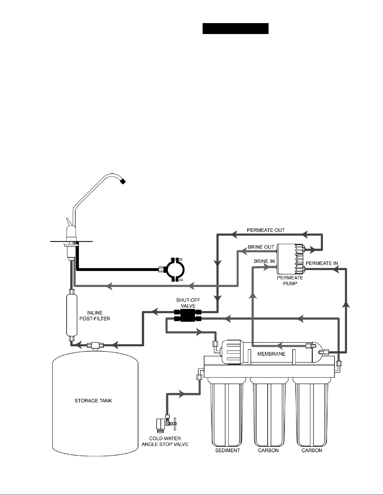
7. Make sure your installation matches the diagram shown in
Figure 1.
8. Turn on the water supply. Check for leaks periodically for the
next 24-48 hours as the system fills and again after it shuts off
when the tank is full.
⁄4" waste line from the membrane (after the ow restric-
1
⁄4" red tube from the faucet air gap inlet into the
3
⁄8" BLACK TUBE DRAIN
RED TUBE
BLUE TUBE
BLUE TUBE
RED TUBE
GREEN TUBE
GREEN TUBE
Figure 1: Standard System after installation of Permeate Pump
3
Page 4

Permeate Pump Installation
with the Manifold System
Parts Needed
(1) Permeate Pump with mounting clip
(2) Quick-Connect Reducer Union
(2) 3" long,
(1) 48" long,
3
(1)
3
(1)
NOTE: The Permeate Pump is equipped with ¼" Quick-Connect
push-to-connect fittings. The pump can be used in RO systems
with
port on the Permeate Pump and attaching a Quick-Connect
Reducer Union to the tubing. Also, when mounting the Permeate Pump, make sure the outlet ports of the Permeate Pump are
above the inlet ports in order to allow entrapped air to escape
1
⁄4" Blue tubes
1
⁄4" Blue tube
⁄8" Quick-Connect Union Tee
⁄8" Plug Insert
3
⁄8" tubing by inserting a short piece of 1⁄4" tubing into the
Installation Steps
1. Turn off the incoming water to the reverse osmosis unit. Lift the
handle on the reverse osmosis drinking water faucet to drain the
water from the system and storage tank.
Note: If tank is equipped with a ball valve, close valve to
preserve the tank water.
2. Before installing the Permeate Pump, remove the blue tube inserts from the ports. Refer to the diagram on Page 2 for instructions for disconnecting from a Quick-Connect fitting.
3
3. Remove the
insert the
4. Locate the
cut approximately 24" from the manifold and re-route into the
Permeate Pump “PERMEATE IN” port using a Reducer Union
and a 3" long,
5. Insert the
“PERMEATE OUT” port using a Reducer Union and a 3" long,
1
⁄4" Blue tube.
6. Locate the
Pump, and then cut and insert the
7. Insert the
3
⁄8" Union Tee
the
8. Locate the
and the faucet air gap inlet and then cut the tube 24" from the
manifold (Making sure to leave the ow restrictor plugged into
the manifold) Insert the red tube from the manifold into the Permeate Pump “BRINE IN” port and the red tube from the faucet
into the Permeate Pump “BRINE OUT” port.
9. Make sure your installation matches the diagram shown in
Figure 2
10. Turn on the water supply. Check for leaks periodically for the
next 24-48 hours as the system fills and again after it shuts off
when the tank is full.
⁄8" Blue tube from the manifold “TANK” port and
3
⁄8" Plug
3
⁄8" Blue tube from the manifold “FAUCET” port and
1
⁄4" Blue tube.
3
⁄8" Blue tube from the faucet into the Permeate Pump
3
⁄8" Blue tube between the faucet and Permeate
3
⁄8" Blue tube leading to the tank into the open port of
1
⁄4" Red tube between the manifold “DRAIN” port
3
⁄8" Union Tee.
4
Page 5

RED
RED
3
⁄8" BLACK
TUBE DRAIN
RED
FLOW RESTRICTOR
BLUE
BLUE
RED
BLUE
BLUE
BLUE
BLUE
GREEN
Figure 2: Manifold System after installation of Permeate Pump
5
Page 6

Permeate Pump Installation
with the KWIK-CHANGE RO
Parts Needed:
(1) 1⁄4" Plug Insert
1
(1)
⁄4" Quick-Connect Union Tee
(1) 48" long,
(1 - Optional) Inline Post Filter
NOTE: When mounting the Permeate Pump, make sure the
outlet ports of the Permeate Pump are above the inlet ports in
order to allow entrapped air to escape
1
⁄4" blue tubing
Installation Steps
1. Turn off the incoming water to the reverse osmosis unit. Lift the
handle on the reverse osmosis drinking water faucet to drain the
water from the system and storage tank.
Note: If tank is equipped with a ball valve, close valve to preserve the tank water.
2. Before installing the Permeate Pump, remove the blue tube inserts from the ports. Refer to the diagram on Page 2 for instructions for disconnecting from a Quick-Connect fitting.
3. Locate the blue tube coming out of the elbow above the blue fil-
ter, then cut the tube 24" from the lters and insert the blue tube
from the filter/manifold into the Permeate Pump “PERMEATE IN”
port
4. Unplug and remove the blue tube located between the shutoff
valve’s “OUT” port and the elbow above the green filter. Insert a
1
⁄4" plug into the elbow.
5. Use the additional blue tube and insert one end into the Permeate Pump “PERMEATE OUT” port that the blue tube was just
removed from.
6. Insert the other end of the additional blue tube into the shutoff
valve’s “OUT” port that the blue tube was just removed from.
7. Cut the blue tube between the tank and shutoff valve and install
1
⁄4" quick-connect union tee.
a
8. Insert the blue tube leading to the faucet into
union tee
1
9. Locate the
⁄4" Red drain tube between the lters and faucet,
and then cut the tube 24" from the lters.
1
10. Insert the
⁄4" Red drain tube, from the lters, into the Permeate
Pump “BRINE IN” port (making sure to leave the ow restrictor
end of the tube plugged into the lter port.)
1
11. Insert the
⁄4" Red drain tube, from the faucet, into the Permeate
Pump “BRINE OUT” port.
12. Make sure your installation matches the diagram shown in
Figure 3
1
13. (Optional) Locate the
⁄4" Blue tube between the faucet and
Quick-Connect union tee and install the inline post filter
1
⁄4" Quick-Connect
6
Page 7

RED TUBE
RED TUBE
BLUE TUBE
BLUE TUBE
BLUE TUBE
GREEN TUBE
Figure 3: KWIK-CHANGE RO after installation of Permeate Pump
7
Page 8

LIMITED WARRANTY: Certain Watts Pure Water products come with a limited warranty from Watts Regulator Co. Other products may have no warranty or are covered by the original manufacturer’s
warranty only. For specic product warranty information, please visit www.watts.com or the published literature that comes with your product. Any remedies stated in such warranties are exclusive and
are the only remedies for breach of warranty. EXCEPT FOR THE APPLICABLE PRODUCT WARRANTY, IF ANY, WATTS MAKES NO OTHER WARRANTIES, EXPRESS OR IMPLIED. TO THE FULLEST EXTENT
PERMITTED BY APPLICABLE LAW, WATTS HEREBY SPECIFICALLY DISCLAIMS ALL OTHER WARRANTIES, EXPRESS OR IMPLIED, INCLUDING BUT NOT LIMITED TO THE IMPLIED WARRANTIES OF
MERCHANTABILITY AND FITNESS FOR A PARTICULAR PURPOSE, AND IN NO EVENT SHALL WATTS BE LIABLE, IN CONTRACT, TORT, STRICT LIABILITY OR UNDER ANY OTHER LEGAL THEORY, FOR
INCIDENTAL, INDIRECT, SPECIAL OR CONSEQUENTIAL DAMAGES, INCLUDING, WITHOUT LIMITATION, LOST PROFITS OR PROPERTY DAMAGE, REGARDLESS OF WHETHER IT WAS INFORMED ABOUT
THE POSSIBILITY OF SUCH DAMAGES.
A Watts Water Technologies Company
USA: Tel. (800) 224-1299 • www.watts.com
Canada: Tel. (888) 208-8927 • www.watts.ca
IOM-WQ-PWPERMKIT 1225 EDP# 2915894 © 2012 Watts
 Loading...