


INSTALLATION, OPERATION AND MAINTENANCE MANUAL
Warning
Please read carefully before proceeding with installation. Your failure to follow any attached instructions or operating parameters may lead to the product’s failure.
Save manual for future reference
Model: RO-PURE Plus
SystemTested and certified by WQA against NSF/ANSI Standard 58 for the reduction of the claims specified on the performance data sheet, and NSF/ANSI 372 for “Lead Free” compliance.
Refer to enclosed warranty for operating parameters to ensure proper use with your water supply.
Watts Premier
Phone: 800-752-5582
Manual: 199519
8716 W Ludlow Drive, Suite 1
www.premierH2o.com
Page 1
Peoria, AZ 85381
Fax: 623-866-5666
Manual Date: 07/20/2016

Thank you for your purchase of a state of the art Premier Reverse Osmosis (RO) water treatment system. Water quality concerns are becoming more of a focus for the public. You may have heard about contaminants in the drinking water such as Arsenic, Chromium, Cryptosporidium or Giardia. There may also be some local water issues such as high levels of Lead and Copper. This Premier water treatment system has been designed and tested to provide you with high quality drinking water for years to come. The following is a brief overview of the system.
Your Reverse Osmosis System:
Osmosis is the process of water passing through a semi permeable membrane in order to balance the concentration of contaminants on each side of the membrane. A semi permeable membrane is a barrier that will pass only certain particles like clean drinking water, but not other particles like arsenic and lead.
Reverse osmosis uses a semi permeable membrane; however, by applying pressure across the membrane, it concentrates contaminants (like a strainer) on one side of the membrane, producing crystal clear water on the other.
This is why RO systems produce both clean drinking water and rinse water that is flushed from the system. This reverse osmosis system also utilizes carbon block filtration technology, and can therefore provide a higher quality drinking water than carbon filtration systems alone.
Your system is a four stage RO which is based upon separate treatment segments within the one complete water filtration system. These stages are as follows:
Stage 1 – Sediment filter, recommended change 6 months.
The first stage of your RO system is a five micron sediment filter that traps sediment and other particulate matter like dirt, silt and rust which affect the taste and appearance of your water.
Stage 2 – Carbon filter, recommended change 6 months.
The second stage contains a 5 micron carbon block filter. This helps ensure that chlorine and other materials that cause bad taste and odor are greatly reduced.
Stage 3- Membrane, recommended change 2-5 years.
Stage three is the heart of the reverse osmosis system, the 50GPD (Gallons Per Day) RO membrane. This semi permeable membrane will effectively remove TDS, Sodium and a wide range of contaminants such as Chromium, Arsenic, Copper, Lead as well as Cysts, such as Giardia and Cryptosporidium. Because the process of extracting this high quality drinking water takes time, your RO water treatment system is equipped with a storage tank.
Stage 4- VOC Block filter, recommend change 12 months.
Premier RO-Pure Plus system conforms to NSF/ANSI 58 for VOC reduction. Through the specialty (VOC) like MTBE’s, Atrazine, Benzene, 2,4-D,Lindane and others from your drinking water. It is estimated that VOC’s are present in one-fifth of the nation’s water supplies. These water contaminants can enter ground water from a variety of sources including localized use of herbicides and pesticides, gasoline or oil spills, leaking underground fuel tanks, septic system cleaners, and chemicals used in the dry-cleaning industry. See performance data sheet for individual contaminants and reduction performance.
Note: Filter & Membrane life may vary based upon local water conditions and/or use patterns.
System Maintenance
Just because you cannot taste it, does not mean that it is not there. Contaminants such as Lead, Chromium andArsenic are undetectable to the taste. Additionally, over time if you do not replace the filter elements, other bad tastes and odors will be apparent in your drinking water.
It is important to change out your filters at the recommended intervals as indicated in this system manual. When replacing the filter elements, pay special attention to any cleaning instructions. Should you have any further questions please refer to our web site at www.premierH2o.com or call our customer service department at 1-800-752-5582.
Page 2
** Before installation, please take a moment to fill out the warranty card on page 23. |
|
Table of Contents |
|
Operational Parameters................................................................................................................... |
4 |
Contents of Reverse Osmosis System............................................................................................ |
4 |
Installation & Startup |
|
Tools Recommended For Installation............................................................................................... |
4 |
Plumbing diagram and parts list...................................................................................................... |
5 |
Drill a Hole for the Reverse Osmosis Faucet................................................................................... |
6 |
How to use Quick Connect Fittings on Your RO System ................................................................ |
6 |
Faucet Installation ........................................................................................................................... |
7 |
Adapt-a-Valve Installation ................................................................................................................ |
8 |
Drain Saddle Installation.................................................................................................................. |
9 |
Drain Saddle Tube Connection........................................................................................................ |
9 |
Blue Tube Connection.................................................................................................................... |
10 |
Red Tube Connection.................................................................................................................... |
10 |
Green Tube Connection.................................................................................................................. |
11 |
Reverse Osmosis Module Mounting............................................................................................... |
11 |
Tank Ball Valve Installation.............................................................................................................. |
11 |
Blue Tube Connection (From The Storage Tank to Shut Off Valve)................................................ |
11 |
Start up Instructions....................................................................................................................... |
12 |
Maintenance & Troubleshooting |
|
Changing The Filter Cartridges...................................................................................................... |
13 |
Membrane Replacement ............................................................................................................... |
13 |
Annual Sanitization ........................................................................................................................ |
14 |
Check Air Pressure in the Tank...................................................................................................... |
15 |
Procedure for Extended Non-Use (More than 2 months)............................................................... |
15 |
Troubleshooting ............................................................................................................................. |
16 |
Product Technical & Warranty Information |
|
Performance Data Sheet................................................................................................................. |
17 |
VOC Performance Data Sheet........................................................................................................ |
18 |
Arsenic Fact Sheet.......................................................................................................................... |
19 |
Service Record................................................................................................................................ |
21 |
Limited Warranty............................................................................................................................. |
22 |
Page 3
Operational Parameters
Installation must comply with State and local plumbing regulations. Do not use with water that is micro biologically unsafe or of unknown quality without adequate disinfection before or after the system. System is intended to be installed using the cold water supply only.
Operating Temperatures: |
Maximum 100°F (37.8°C) |
Minimum 40°F (4.4°C) |
Operating Pressure: |
Maximum 100 psi (7.0 kg/cm2) |
Minimum 40 psi (2.80 kg/cm2) |
pH Parameters: |
Maximum 11 |
Minimum 2 |
Iron: |
Maximum 0.2 ppm |
|
TDS (Total Dissolved Solids) |
< 1800 ppm |
|
Turbidity |
< 5 NTU |
|
Hardness |
Maximum 10 Grains Per Gallon * |
|
Hardness: Recommended hardness not to exceed 10 grains per gallon, or 170 parts per million.
* System will operate with hardness over 10 grains but the membrane life may be shortened.
Addition of a water softener may lengthen the membrane life.
Water Pressure: The operating water pressure in your home should be tested over a 24 hour period to attain the maximum pressure. If the incoming water pressure is above 100 psi then a water pressure regulator is required. A booster pump is needed for incoming water pressure under 40psi.
Copper Tube: Reverse Osmosis water should not be run through copper tube as the purity of the water will leach copper causing an undesired taste in water and pin holes may form in the tube.
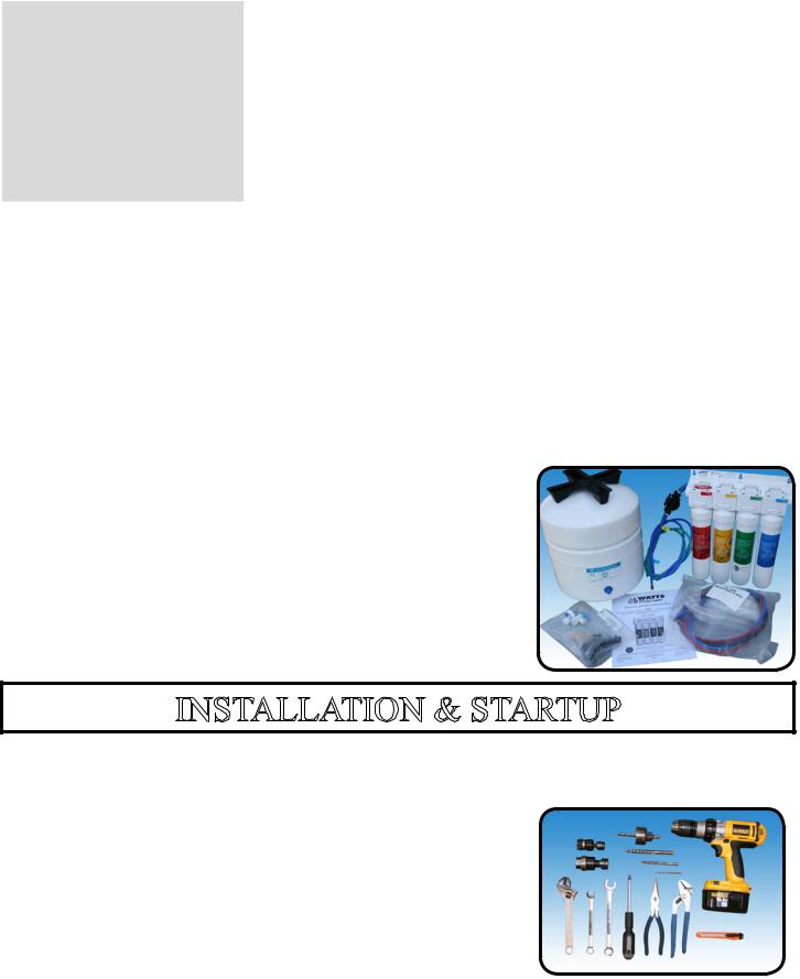
Contents of the Reverse Osmosis (RO) System
1 Tank
1 Module – (Filters Pre-Installed)
1 Parts Bag
1 Faucet Box
1 Manual
If any of the items are missing please contact Premier prior to installing.
INSTALLATION & STARTUP
Tools Recommended For Installation
√ 1 1/4" Diamond Tipped Hole Saw bit for faucet opening (Counter Tops/Porcelain & Stainless Sinks)
√ 1 1/4” Adjustable Wrench |
√ Phillips bit for electric drill |
√ 1/2" Open End Wrench |
√ Needle Nose Pliers |
√ 5/8” Open End Wrench |
√ Adjustable Pliers |
√ Electric Drill |
√ Sharp Knife |
√ 1/8" diamond tip bit, pilot hole |
√ Phillips Screw Driver |
√ 1/4” drain saddle hole |
|
Page 4
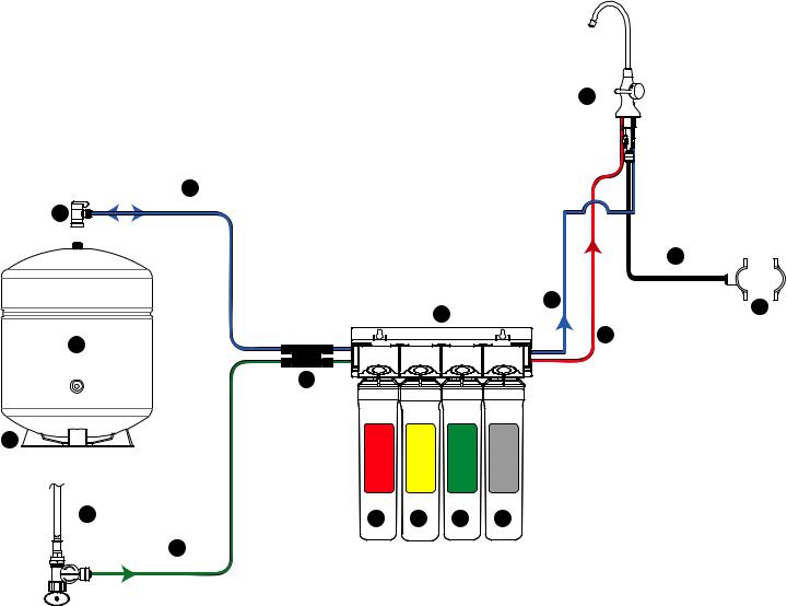
Plumbing Diagram and Parts List
6
3 TANK
8
4 ADAPT -A- VALVE
COLD WATER ANGLE-STOP
(SUPPLY)
5 FAUCET
10
BLUE - 1/4” TUBE
TANK
1
2 |
AUTO SHUT-OFF VALVE |
BLUE - 1/4” TUBE
10
FAUCET |
|
- 1/4” TUBE BRINE |
|
RED |
12 |
|
|
11
BLACK - 3/8” TUBE 
 DRAIN
DRAIN
7
DRAIN SADDLE
13 |
14 |
15 |
16 |
9
GREEN- 1/4” TUBE
FEED
Part No. Description
1115304 FILTER MODULE
2134003 AUTOMATIC SHUT OFF VALVE
3 |
119007 STORAGE TANK - 3 GALLONS |
4560080 ADAPT-A-VALVE KIT
5420102 FAUCET - TMT - BRUSHED NICKEL
6134018 TANK VALVE - 1/4F X 1/4” QC
7164056 DRAIN SADDLE - 3/8” QC - KIT
8119028 TANK STAND
9142000 1/4” GREEN TUBING WITH 90° BEND - 4FT
10142001 1/4” BLUE TUBING WITH 90° BEND - 4FT
11400048 3/8” BLACK TUBING - 3FT X 1
12142002 1/4” RED TUBING WITH 90° BEND - 4FT
13105311 SEDIMENT PRE-FILTER (RED)
14105351 CARBON PRE-FILTER (YELLOW)
15105331 REVERSE OSMOSIS MEMBRANE 50GPD (GREEN)
16105381 VOC CARBON POST FILTER (SILVER)
Page 5

Drill a Hole for the Reverse Osmosis Faucet
Marble Counter-top
We recommend contacting a qualified contractor for drilling a hole in a marble counter-top.
Counter Top / Porcelain & Stainless Steel Sink
Note: Most sinks are pre drilled with 1 ¼” diameter hole that you can use for your RO faucet. (If you are already using it for a sprayer or soap dispenser, see step 1)
Porcelain sinks are extremely hard and can crack or chip easily.
Use extreme caution when drilling. Watts accepts no responsibility for damage resulting from the installation of faucet. Diamond tip bit recommended.
Step 1 Determine desired location for the RO faucet on your sink and place a piece of masking tape over where the hole is to be drilled. Mark the center of the hole on the tape.
Step 2 Using a variable speed drill set on the slowest speed, drill a 1/8“ pilot hole through both porcelain and metal casing of sink at the marked center of the desired location. Use lubricating oil or liquid soap to keep the drill bit cool (If drill bit gets hot it may cause the porcelain to crack or chip).
Step 3 Using a 1 ¼” diamond tip hole saw, proceed to drill the large hole. Keep drill speed on the slowest speed and use lubricating oil or liquid soap to keep the hole saw cool during cutting.
Step 4 After drilling, remove all sharp edges and make sure the surroundings of the sink are cooled before mounting the faucet.
How to use the Quick Connect Fittings
To make a connection, the tube is simply pushed into the fitting. The unique locking system holds the tube firmly in place without deforming it or restricting flow. Use the steps below in reference to any quick connect tube connections.
It is essential that the outside diameter be free of score marks and that burrs and sharp edges be removed before inserting into fitting.
Push the tube into the fitting, to the tube stop. The collet
(gripper) has stainless steel teeth which hold the tube firmly in position while the O-ring provides a permanent leak proof seal.
Fitting grips before it seals. Ensure tube is pushed into the tube stop.
Pull on the tube to check that it is secure. It is a good practice to test the system prior to leaving site and /or before use.
To disconnect, ensure the system is
depressurized before removing the tube. Push in the collect squarely against face of fitting. With the collet held in this position, the tube can be removed. The fitting can then be reused.
Page 6
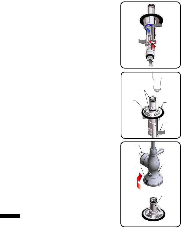
Premier Monitored (Top Mount Twist) Faucet Installation
Connect tubes to the RO faucet (Figure A)
This RO faucet is equipped with quick connect fittings for easy tube installation.
1.In the parts bag, locate one 1/4” red tube, one 1/4” blue tube and one 3/8” black tube.
2.Connect the STRAIGHT END of the 1/4”-BLUE tube to the corresponding fitting at the base of the faucet. Make sure the tube is inserted the full
3/4” into the fitting.
3.Connect the STRAIGHT END of the 1/4”-RED tube to the corresponding fitting at the base of the faucet. Make sure the tube is inserted the full
3/4” into the fitting.
4.Connect the 3/8” BLACK tube to the fitting at the base of the faucet with the black ring. Make sure the tube is inserted the full 3/4” into the fitting.
Mount the RO faucet (Figure B)
NOTE: A 1.25” mounting hole is required for faucet installation.
5.Make sure the Locking Tabs are “tucked”. Feed the tubes and the lower faucet assembly through the mounting hole in the sink. Test fit faucet placement.
6.Make sure the lower faucet assembly is seated properly inside of the rubber washer groove
NOTE: Arrow on base indicates FRONT of faucet.
6.Using a Phillips screwdriver, tighten the two screws until snug. Then, tighten each screw alternately until faucet is secure. Do not overtighten!
7.Inspect O-rings on lower faucet assembly. Lubricate with water-soluble lubricant if needed.
Assemble Faucet (Figure C)
7.Align the release button on the back of the upper faucet assembly approximately 45° left off the back of the lower faucet assembly.
8.Press the upper faucet assembly firmly on-to the lower faucet assembly and twist clockwise until locked into place. Remove battery cover on faucet handle, pull battery tab and replace battery cover.
To Remove Upper Assembly:
Press in the release button and twist upper faucet assembly counterclockwise.
 Do not remove upper faucet assembly until all water has been drained from the system and system has been fully depressurized.
L.E.D. FAUCET MONITOR INDICATOR
This faucet is equipped with a filter change indicator. The indicator light will flash BLUE while the water is being dispensed.After approximately six months or 2000 gallons of filtered water used the light will change to RED, indicating that filters should be changed. After filter change you must reset the monitor (Follow the Faucet Indicator Battery Replacement procedure on page 8).
 DANGER This product contains a button cell battery. If swallowed, it could cause severe injury or death in just 2 hours. Seek medical attention immediately.
INSERT
1/4”-BLUE TUBE
INSERT
1/4”-RED TUBE
Figure A |
3/8”-BLACK TUBE |
|
INSERT |
LUBRICATE
O-RINGS
FRONT |
RUBBER |
|
|
|
WASHER |
LOCKING
TABS
Figure B
BATTERY
TAB
RELEASE |
UPPER |
|
FAUCET |
||
BUTTON |
||
ASSEMBLY |
||
|
TWIST
UPPER ASSEMBLY 45° ONTO
BASE LOWER
FAUCET
ASSEMBLY
BACK |
|
Figure C |
FRONT |
|
Page 7
 Loading...