

Page 1
Installation, Operation
and Maintenance Manual
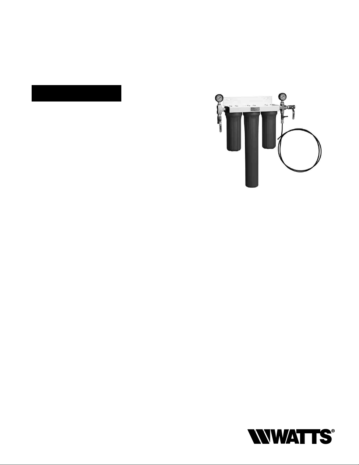
3-Stage Filtration
Model PWICE2
PURE WATER
Important
Please read the entire manual before proceeding with the
installation and startup. Your failure to follow any attached
instructions or operating parameters may lead to the product’s
failure.
Save manual for future reference
IOM-WQ-PWICE2
PWICE2
Table of Contents
System Specifications .................................2
Notice to Installers ....................................2
Installation Precautions ................................2
Operation ..........................................3
Installation ..........................................3
Maintenance ........................................3
Filter Cartridge Replacement Procedure ...................3
Replacement Parts List ................................3
Note: Do not use with water that is microbiologically unsafe or
of unknown quality without adequate disinfection before or after
the system.
Page 2

System Specifications
Maximum Pressure: 125psi (8.6 bar)
Maximum Temperature: 100°F (38°C)
Inlet/Outlet Connections: ½" (15mm) FNPT
Maximum Flow Rate: 3 GPM
Filter Cartridge Life Span
Filter cartridges should be changed at 10,000 gallons, 15psi overall
system pressure drop at normal flow rate, or 6 months, whichever
comes first.
Replacement Filter Pack
MODEL FREQUENCY DESCRIPTION
PWFPKICE2 6 Months 10" Sediment filter
20" Carbon Block filter
10" Phosphate filter
Note: Water conditions may require more frequent cartridge replacement
Please note: Cartridge capacities are estimates and may be less
depending on incoming water quality. Cartridges should be changed
at least every 6 months.
Notice to Installer
• Do not discard this manual after installation. This manual contains
important operation, maintenance and precautionary information.
Please present this manual to the user/owner/operator after installation.
• It is strongly suggested that you read this manual before installing
system to ensure the best possible installation.
• Installation must comply with all local and state plumbing codes
and regulations.
• Connect the system to cold water supply only. Water Temperature
cannot exceed 100°F (38°C).
• System must be installed in a vertical, upright and level position.
• Do not use with water that is microbiologically unsafe or of un-
known water quality.
• Notice to user/owner/operator: Please retain this manual for future
reference for parts, maintenance, or troubleshooting.
• It is recommended that all personnel responsible for operation and
maintenance of this product read the precautions, maintenance,
and operation sections of this manual.
Installation Precautions
• Do not install system on line pressure above 125 psi (8.6 bar).
• Do not install the system on a hot water line. Failure to limit the
water temperature to 100°F (38°C) can result in housing failure and
property damage.
• Do not connect the system backwards with the feed water line
connected to the outlet.
• Do not use liquid pipe thread compounds for threaded connections. Use Teflon
• Do not solder plumbing connections that are attached to the housings or inlet/outlet fittings. System damage may occur due to high
temperature.
• Do not allow the system to freeze. Turn off water supply and drain
the system if temperature falls below 32°F (0°C).
• Do not install system in direct sunlight or where the system will be
exposed to harsh chemicals or may be subjected to being hit by
moving equipment, carts, mops, or any other item that may cause
damage.
• Allow 3" (76mm) minimum clearance under the housings for lter
replacement.
• If water hammer is evident, install water hammer arrestors before
the system.
• Do not over tighten tting connections.
• Always back up valves and ttings with a wrench when installing
fittings to avoid over tightening or loosening existing fittings.
• Do not install the unit behind equipment where it may be difcult to
access the system for future filter replacements.
Position the system in a suitable location. The direction of flow
through the system is left to right. Keep this in mind when determining installation locations. Do not mount the system near any source
of heat. Also do not mount this system over anything that may be
adversely affected by water.
®
tape only.
®
is a registered trademark of E.I. Dupont de Nemours & Company.
Teflon
2
Page 3

Operation
With sufficient pressure, operation of this system is completely automatic. Dependable operation involves only monitoring system pressure differential, periodic filter changes, and service documentation.
Maintenance
Routine maintenance of this system involves periodic filter changes.
The filters should be replaced after 6 months, high pressure differential (15psi or more), or chlorine breakthrough (10,000 gallons), which
ever comes first.
Installation
* Please note: All cartridge filters are preinstalled, in the
housings, at the factory.
1. Turn off all equipment to be fed by the system, locate the water
supply shutoff valve and turn it off.
2. Thread the inlet and outlet valve and pressure gauge assemblies
into the inlet and outlet of the system. The valve and pressure
gauge assembly with the ¼" (8mm) Quick-Connect fitting is to
be installed on the outlet of the system. NOTE: DO NOT OVER
TIGHTEN THESE FITTINGS INTO THE FILTER HEADS.
3. Anchor the system on a wall stud or suitable mounting material
spanning wall studs. System must be vertical, upright and level.
1
4. Run a suitable line of at least
source to the inlet ball valve on the left side of the system. Brace
the inlet ball valve on the system with a wrench when connecting
the feed water line. NOTE: DO NOT OVERTIGHTEN CONNEC-
TION FITTING INTO BALL VALVE.
5. Select the appropriate size tubing for the equipment being fed,
and connect it to the outlet ball valve of the system. NOTE: DO
NOT OVERTIGHTEN CONNECTION FITTING INTO BALL
VALVE.
6. Install the ¼" tubing into the compression fitting on the outlet of
the system and hold it over a drain. Open the
7. Once all inlet and outlet piping has been completed, check and
make sure all filter housing are tight, slowly open the inlet valve
and allow all air to purge from the system. Slowly close the
drain valve, allow the system to reach operating pressure, and
check for leaks.
8. If no leaks are present, open the
to run to drain for 5 minutes to flush the system then close the
valve.
9. Open the outlet water valve and check for leaks.
10. Record the start up date and pressures in this manual.
Note: Overtightening components can damage the system
causing water damage and/or system failure.
⁄2" in diameter from the tap water
1
⁄4" drain valve.
1
⁄4"
1
⁄4" drain line again and allow it
Filter Cartridge Replacement Procedure
IMPORTANT: Determine whether all equipment connected to
the system must be turned off prior to shutting off water supply
from filters.
1. If required, turn off downstream equipment.
2. Turn OFF water to the system by closing the inlet and outlet ball
valves.
1
3. Open the
⁄4" drain valve on the outlet of the system to relieve
pressure in the housings.
4. Remove housings by unscrewing them. They have a standard
right hand thread.
5. Clean inside of housing sump with warm water. If desired, disin-
fect housing using a teaspoon of household bleach. Add to lter
bowl and fill with water. Let stand 5 minutes and then discard
and rinse.
6. Insert new cartridges into filter housings.
7. Make certain the O-ring is properly positioned and reinstall lter
housings. Tighten housings hand tight. Check O-ring for damage and replace if damaged or distorted.
Do not overtighten filter housing, overtightening may damage
O-ring(s), cause water leaks, or affect system performance.
1
8. Slightly open the inlet ball valve and fully open the
⁄4" drain
valve. Once full flow of water flows from the drain port, slowly
open the inlet valve to the full open position. Allow water to ush
to drain for 5 minutes.
9. Slowly close the drain valve and check the system for leaks.
10. Slowly open the outlet valve to restore water flow to downstream
equipment.
11. Record filter change date in this manual.
Replacement Parts List
PWICE2 Maximum Flow Rate: 3 gpm
OUT
1
FPT
⁄2"
To Ice
Maker
1
FPT
IN
⁄2"
1
⁄4" O.P.
Flush
(Front to Back)
⁄2"
1
Height 26
Note: Allow 3" of clearance at
bottom of system for removal
of filter bowls for filter cartridge
replacement
ITEM NUMBER DESCRIPTION QUANTITY
Width 251⁄4"
Line
1 Sediment Filter 20 Micron 10" 1
2 Carbon Block Filter 5 Micron 20" 1
3 Phosphate Filter 10" 1
4 Pressure Gauge 2
5 Filter Housing O-ring 3
6 10" Filter Housing Assembly 2
7 20" Filter Housing Assembly 1
3
Depth 51⁄8"
Page 4

LIMITED WARRANTY: Certain Watts Pure Water products come with a limited warranty from Watts Regulator Co. Other products may have no warranty or are covered by the original manufacturer’s
warranty only. For specic product warranty information, please visit www.watts.com or the published literature that comes with your product. Any remedies stated in such warranties are exclusive and
are the only remedies for breach of warranty. EXCEPT FOR THE APPLICABLE PRODUCT WARRANTY, IF ANY, WATTS MAKES NO OTHER WARRANTIES, EXPRESS OR IMPLIED. TO THE FULLEST EXTENT
PERMITTED BY APPLICABLE LAW, WATTS HEREBY SPECIFICALLY DISCLAIMS ALL OTHER WARRANTIES, EXPRESS OR IMPLIED, INCLUDING BUT NOT LIMITED TO THE IMPLIED WARRANTIES OF
MERCHANTABILITY AND FITNESS FOR A PARTICULAR PURPOSE, AND IN NO EVENT SHALL WATTS BE LIABLE, IN CONTRACT, TORT, STRICT LIABILITY OR UNDER ANY OTHER LEGAL THEORY, FOR
INCIDENTAL, INDIRECT, SPECIAL OR CONSEQUENTIAL DAMAGES, INCLUDING, WITHOUT LIMITATION, LOST PROFITS OR PROPERTY DAMAGE, REGARDLESS OF WHETHER IT WAS INFORMED ABOUT
THE POSSIBILITY OF SUCH DAMAGES.
A Watts Water Technologies Company
USA: Tel. (800) 224-1299 • www.watts.com
Canada: Tel. (888) 208-8927 • www.wattscanada.ca
IOM-WQ-PWICE2 1225 EDP# 2915882 © 2012 Watts
 Loading...