

Page 1

Installation, Operation
and Maintenance Manual
Series PWBWIRONZ Filter Systems
PURE WATER
!
Warning
You are required to thoroughly read all installation instructions and product instructions and product safety information
before beginning the installation of this product. FAILURE TO
COMPLY WITH PROPER INSTALLATION AND MAINTENANCE
INSTRUCTIONS COULD RESULT IN PROPERTY DAMAGE,
PERSONAL INJURY AND/OR DEATH. Watts is not responsible
for damages resulting from improper installation and/or maintenance.
Do not use with water that is microbiologically unsafe or of
unknown quality without adequate disinfection before or after
the system.
Local building or plumbing codes may require modifications to
the information provided. You are required to consult the local
building and plumbing codes prior to installation. If this information is not consistent with local building or plumbing codes, the
local codes should be followed.
Save manual for future reference
Refer to enclosed warranty for operating parameters to ensure
proper use with your water supply.
IOM-WQ-PWBWIRONZ
PWBWIRONZ
Table of Contents
Important Safety Information - Read All . . . . . . . . . . . . . . . . . . . . . . . 2
Instructions Before Using.................................. 2
Filter Anatomy ..........................................2
Specifications ..........................................3
Feed Water Parameters................................... 3
Power ................................................3
System Overview........................................ 3
Installation - Set Up ...................................... 4
Installation - Overview ....................................4
Control Valve Component Identification . . . . . . . . . . . . . . . . . . . . . . . 4
Deflector Installation .....................................4
Installation - Considerations................................ 5
Drain Requirements ......................................5
Installation .............................................5
Programming...........................................7
Controller Operation .....................................7
Troubleshooting.........................................8
Limited Warranty ........................................8
Page 2
I. Important Safety Information –
Read All
!
CAUTION: Read and follow the information in this manual
to minimize the risk of electric shock or personal injury.
Important: If you are unsure about installing your Watts water
filter, contact a Watts representative or consult a professional
plumber.
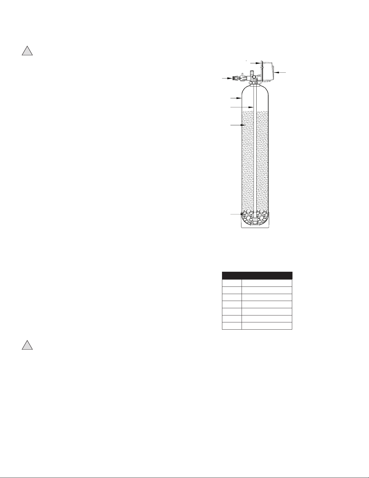
Filter Anatomy
1
6
2
A. READ Instructions Before Using
• After reading these instructions completely, obtain all the
materials and tools needed for installation.
NOTE: Failure to install the system correctly voids the warranty.
• Perform installation according to state, province and local
plumbing codes.
Use only lead-free solder and flux for sweat-solder
connections, as required by state, province and federal
codes.
• Handle all components of the system with care. Do not drop,
drag or turn components upside down.
• Be sure the oor under the water lter system is clean, level
and strong enough to support the unit.
• The system uses 24 volt-60Hz electrical power. Always use
the transformer supplied.
Plug transformer into an indoor 120 VAC, grounded outlet.
Properly ground the system to conform with all codes and
ordinances.
• Install the system in a protected area. Be sure electric outlet
and transformer do not come in contact with water. See
Installation Considerations, in the installation section of the
manual.
Do not attempt to treat water over 110°F (43°C) with the
system. Always connect the system to the main water
supply pipe before the water heater.
Do not expose the system to freezing temperatures. Wa-
ter freezing in the system causes equipment damage.
Do not install in direct sunlight. Ultraviolet rays from the
sun may cause damage.
• Minimum inlet water pressure is 30 psi. Maximum inlet water
pressure is 80 psi. Use a pressure reducing valve if neces-
sary.
3
4
5
7
Figure 1
ITEM DESCRIPTION
1 Control Valve
2 Bypass Valve
3 Mineral Tank
4 Distributor Tube
5 Filter Media
6 Faceplate/Control
7 Gravel Underbedding
!
CAUTION:
• Do not use with water that is microbiologically unsafe or of
unknown quality.
• Test the water periodically to verify that the system is performing satisfactorily.
• Discard small parts remaining after the installation.
2
Page 3

Specifications
MODEL VALVE MINERAL TANK MEDIA VOLUME GRAVEL PEAK SERVICE PRESSURE DROP BACK WASH FLOOR SPACE REQUIRED
TYPE SIZE (DXH) CUBIC FOOT (LBS) FLOW (GPM) @PEAK FLOW (PSI) FLOW (GPM) (L X W X H)
PWBWIRONZ1 Time Clock 9" x 48" 1 12 6 <15 7 16" x 15" x 55"
PWBWIRONZ1.5 Time Clock 10" x 54" 1.5 12 8 <15 8 16" x 15" x 62"
PWBWIRONZ2 Time Clock 12" x 52" 2 25 11 <25 12 17" x 15" x 60"
PWBWIRONZ3 Time Clock 13" x 65" 3 30 13 <25 15 18" x 15" x 74"
Note: Peak service flow rate is for intermittent use only and is not to be interpreted as continuous service flow rate capability. These
systems are designed to treat the domestic water used in a single family dwelling. For irrigation water treatment or higher volume
applications please contact your Watts representative.
Feed Water Parameters
!
Do not use this system on water that is microbiologically
unsafe or of unknown quality without adequate disinfection
before or after the system!
Minimum inlet pressure: 30 psig
Maximum operating pressure: 80 psig
Minimum water temperature: 34°F (1°C)
Maximum water temperature: 110°F (43°C)
Maximum iron content: 10 PPM
Maximum hydrogen sulfide content: 3 PPM
Effective pH range: 6.5-9
Location: Indoors (Protect from direct sunlight)
Minimum ambient temperature: 34°F (1°C)
Maximum ambient temperature: 122°F (50°C)
Power
Voltage: 120VAC
Frequency: 60Hz
Installation
Location: Indoors (Protect from direct sunlight)
PWBWIRONZ System Overview
PWBWIRONZ systems are selected for use when the concentration
of iron and hydrogen sulfide in water need to be reduced. They
use the model 2510 AIO Control Valve to reduce the contaminants
in the water without the use of chemicals. The 2510 AIO valve is
specially designed to capture a volume of air inside the system’s
mineral tank. Water passes through the AIO valve then passes
through the air head in the top of the mineral tank. Oxygen from
the captured air transfers into the water. The oxygen oxidizes these
contaminates in the water to oxides or solid precipitants. Then they
are mechanically filtered out of the water by the Micro Z® media
filter bed. After a preprogrammed number of days have passed, the
system will perform a regeneration cycle to clean the Micro Z® media
of the solids it has accumulated, draw in more air, rinse, then return
to service. Watts recommends a daily regeneration of the system. A
regeneration every other day may be possible if system inlet water
quality permits (please contact your Watts representative).
Regeneration is as follows:
Backwash (BW): The Backwash cycle washes oxidized contaminCycle Step #1 ates to drain and reclassifies the media bed.
Air Draw (BD): Air Draw empties water from the tank and replen-
Cycle Step #2 ishes the oxygen within the mineral tank.
Rapid Rinse (RR): Rapid Rinse purges excess atmosphere from the
Cycle Step #3 mineral tank and distributor.
Upon completion of Rapid Rinse the system returns to the service
position.
NOTE: Due to the presence of air in the media tank the maximum operating pressure of the system is 80 psi.
3
Page 4

II. Installation
A. Setup
Unpack and check the system components for damaged or missing parts. Make sure that the bypass valve and plumbing yoke are
properly connected to each other and to the control valve with the
mounting clips. Make certain that the drain line flow control fitting
is installed properly on the drain port of the control valve. Systems
that are 13" in diameter and larger are not loaded with media. These
systems must be loaded with media before placing into service. To
load a system follow the below steps.
1. Cap the top open end of the distributor tube with tape and plas-
tic sheeting to keep foreign debris from entering the distributor
tube. This cap must be secure and not come off during media
loading.
2. Place the distributor tube, screen end down, into the mineral
tank and center it in the bottom. The top of the distributor tube
should be flush with the top of the tank.
3. Make sure the plastic and tape cap is secure to the top of the
distributor tube, place a funnel on the top of the tank and load
first the gravel then the Micro Z® media into the tank. The cap
must not come off of the distributor tube during the loading of
the media.
4. Remove the plastic cap from the distributor tube. DO NOT PULL
UP ON THE DISTRIBUTOR TUBE when removing the cap. The
distributor tube top must remain flush with the top of the tank.
5. Clean any media from the threads and top of the mineral tank
and install the deflector disk. See D. Deflector Installation section
for more details.
6. Lubricate the O-rings on the bottom of the control valve (dis-
tributor pilot O-ring and top of tank O-ring). Use non-petroleum
based silicone lubricant only.
7. Place the control valve on top of the tank. When doing this step,
seat the top of the distributor tube inside the centered O-ring
sealed port on the bottom of the valve first then press the valve
down until the tank threads come in contact with the valve
threads. This ensures that the distributor tube is properly seated
into the bottom of the control valve. Thread the valve on to the
tank clockwise. Be careful not to cross thread the valve or over
tighten it. A hand tight snug fit is appropriate for the control valve
torque. A wrench is not necessary. Do not use thread sealant or
PTFE tape on the threads.
8. The system is now ready for installation.
B. Installation Overview
Install the system after the supply lines to the outside faucets. This
system should be installed before a water softener or any taste/odor
cartridges, if applicable.
Ensure the inlet check valve item #5 is connected as shown in
Figure 2 to the inlet side of the 2510 AIO valve. The drain should be
installed in accordance with plumbing codes. Due to the release of
air during regeneration, the drain line should be anchored throughout
the run, secured at the end of the drain line, and properly vented.
The drain line should be sized for the backwash rate listed under
Drain Requirements taking into account friction loss.
C. 2510 AIO Control Valve Component
Identification:
4
3
2
1
5
Drain
6
Figure 2
ITEM DESCRIPTION
1 2510 AIO CONTROL VALVE
2 VALVE COVER
3 CHECK VALVE, AIR DRAW VALVE
4 SCREEN, AIR CHECK ADAPTOR
5 INLET CHECK VALVE
6 SCREW, 8-32, SS, 2510AIO
7 DEFLECTOR DISK
D. Deflector Installation
Put a thin layer of silicone lubricant around inside diameter of the
deflector #7. Slowly slide the deflector over the distributor tube down
about 1". When threading the AIO valve to the tank, the bottom of
the threads will slide the deflector down. As shown in Figure 3.
7
Figure 3
4
Page 5

E. Installation Considerations
Consider the following points when determining where to install the
filter:
• Place the system as close as possible to a sewer drain.
• Do not install the lter where it would block access to the water
heater, or access to the main water shutoff, water meter, or electrical panels.
• Install the lter in a place where water damage is least likely to occur if a leak develops.
• A 120VAC electrical outlet is needed to plug in the transformer.
• Always connect the system to the main water supply pipe before
the water heater.
• Install the system where it will not be subject to temperatures
outside of the limits stated in the Specification Section or to direct
sunlight.
F. Drain Requirements
The drain systems these filters are plumbed into must be able to
accept the drain rates listed below. The well or water supply must
be capable of maintaining a 30 psi minimum feed water pressure,
continuously, at these drain flow rates.
MODEL TANK SIZE DRAIN RATE
PWBWIRONZ1 9" x 48", 1 cubic ft. 7 gpm
PWBWIRONZ1.5 10" x 54", 1.5 cubic ft. 8 gpm
PWBWIRONZ2 12" x 52", 2 cubic ft. 12 gpm
PWBWIRONZ3 13" x 65", 3 cubic ft. 15 gpm
III. Valve Installation
1. Turn off gas or electric supply to the water heater.
2. Close the feed water valve to the plumbing system. Then
relieve the pressure in the plumbing by opening the hot and
cold water faucets.
3. Cut the pipes at the installation point. Use a drain pan to catch
any spillage that results.
4. Move the filter system into installation position.
• Be sure the installation point is downstream of the bladder tank
and irrigation system if this system is being installed on a well.
• The installation surface must be strong enough to support the
weight of the system once it is placed into operation.
5. Plumb INLET and OUTLET connections to and from the filter.
• Be sure the incoming water supply is directed to the INLET port
of the valve.
• The valve body of the control is marked with arrows indicating
the proper flow direction.
• Connections are illustrated below in Figure 4 (shown without
bypass and yoke) and Figure 5 (bypass piping detail).
Outlet
Outlet
Inlet
Inlet
rai
D
Drain
n
Figure 4
6. Connect and route the valve drain line using rigid piping or
hose. Use the same size plumbing for the drain line as the fitting provided for the drain connection. The smallest units have
a 1⁄2" connection, the medium sized units have a 3⁄4" connection, and the largest units have a 1" connection. It is important
to use the same size plumbing as the connection to ensure
proper backwash flow.
Note: Leave an air gap of at least 11⁄2" between the end of the
drain plumbing and the drain point.
CAUTION: If making a soldered copper installation, do all
sweat soldering before connecting pipes to the bypass valve.
Torch heat will damage plastic parts.
CAUTION: When turning threaded pipe fittings onto plastic
fittings, use care not to cross-thread or overtighten.
CAUTION: Use PTFE tape on all external pipe threads. Do not
use pipe joint compound.
CAUTION: Support inlet and outlet plumbing in some manner
(use pipe hangers) to keep the weight off of the control valve
drain, bypass, and plumbing yoke points of connection.
5
Page 6

III. Installation (cont.)
7. Place the bypass valves into the "bypass" position as shown
below in Figure 5 by rotating the bypass handles. The handles
will point to each other when they are placed into the bypass
position.
Outlet
Inlet
Figure 5
8. Fully open two (2) cold water faucets near the water filter.
9. Fully open the main feed water valve described in step 2.
Observe a steady flow from both faucets.
10. Close all faucets at this time.
11. Check plumbing work for leaks and fix immediately if any are
found.
12. Connect electrical power by plugging the transformer into a
(120 VAC) outlet.
16. Open the outlet bypass valve fully.
17. Open the inlet bypass valve slightly. Open the valve just until
you hear water flowing.
18. Observe the drain flow. It may take several minutes for the
filter vessel to fill up with water and begin to flow water to
drain.
19. After all the air is purged from the vessel and a steady drain
flow is observed, allow the unit to backwash for 10 minutes
with the inlet valve open slightly.
20. After the 10 minutes of backwashing is complete, fully open
the inlet bypass valve and allow the unit to backwash for 90
minutes.
21. After 90 minutes, observe the drain flow. If the drain flow is
clear proceed to the next step. If the drain flow is still cloudy,
allow the system to continue to backwash until it is clear. Do
not capture the drain water in a container to evaluate its clarity. Oxidized impurities in the water will give the drain water
a cloudy appearance if it is caught and viewed in volume.
Evaluate its clarity as it flows out of the open end of the drain
pipe or hose to avoid unnecessary backwashing time.
22. Plug the unit back in to the electrical outlet and allow it to finish backwash, draw, and rinse cycles. This will take approximately 60 minutes.
23. Set the time of day. Press and hold either the Up or Down
buttons until the programming icon replaces the service icon
and the parameter display reads TD. Adjust the displayed
time with the Up and Down buttons. When the desired
time is set, press the Extra Cycle button to resume normal
operation. The unit will also return to normal operation after 5
seconds if no buttons are pressed.
24. Turn on the gas or electric supply to the water heater after
all air has been purged from the house's plumbing system
and water heaters. Flush water heaters and plumbing system
with filtered water to help clear the lines of any residual iron
content.
The system is now ready to be programmed.
13. Open the valve cover to access the timer. Press and hold the
“Extra Cycle” button until the flashing “BW” symbol appears
in the Parameter Display.
14. Slowly, turn the bypass valve back to the "service" position.
In the service position both handles of the bypass valve will
point to the control valve. Then close the inlet bypass valve.
15. Unplug the valve when the “BW” symbol stops flashing and
the countdown timer appears. This keeps the valve in an
extended backwash for the initial startup.
6
Page 7

IV. Programming
Figure 6 shows the icons and display characters of the timer mechanism.
Figure 6
When the Master Programming Mode is entered, all available option/
setting/displays may be viewed and set as needed. Depending on
current option settings, some parameters cannot be viewed or set.
This timer is used on other system configurations as well so it is
important that the user carefully programs the system in accordance
with the values shown on the Master Programming Chart.
A. Setting the Time of Day
1. Press and hold either the Up or Down buttons until the programming icon replaces the service icon and the parameter
display reads TD.
2. Adjust the displayed time with the Up and Down buttons.
3. When the desired time is set, press the Extra Cycle button to
resume normal operation. The unit will also return to normal
operation after 5 seconds if no buttons are pressed.
D. Master Programming Chart
PROGRAMMING
ABBREVIATION
DF Display Format GAL Gallons - 12 hour time
VT Valve Type DF 1b Downflow Single Backwash
CT Control Type tc
NT Number of Tanks 1 Single Tank
DO Day Override 1
RT
BW Backwash 14 See Page 3 for Definition
BD Air Draw 40 See Page 3 for Definition
RR Rapid Rinse 1 See Page 3 for Definition
BF Brine Fill Off Not Applicable
*Factory Default Values
PROGRAMMING
DEFINITION
Regeneration
Time
*OPTION
ABBREVIATION
12:30 AM
OPTION
DEFINITION
Time Clock - Regenerates based
on days
Days Between Regeneration –
DO NOT set the regeneration day
override for a longer period than
two days, as the filter media can
become fouled with contaminates,
rendering the system ineffective.
Regeneration Time – Time of day
regeneration is to occur. Make
sure this time does not overlap
with the regeneration process
of another piece of equipment
such as an existing softener or
media filter.
V. Controller Operation
The factory default program settings should be adequate for most
installations.
A. Queueing a Regeneration
1. Press the Extra Cycle button. The service icon will flash to
indicate that a regeneration is queued. Regeneration will occur
that day at the programmed Regeneration Time (RT).
2. To cancel a queued regeneration, press the Extra Cycle button.
B. Entering Master Programming Mode
The master level programming has been set at the factory however
you should check the program against the Master Programming
Chart. With the control valve in the service position set the Time
Of Day display to 12:01 P.M. Press the Extra Cycle button (to exit
Setting Time of Day mode). Then press and hold the Up and Down
buttons together until the programming icon replaces the service
icon and the Display Format "DF" screen appears. Once you are in
the master programming screen, pressing the extra cycle button
will advance the controller to the next parameter. Pressing the up or
down buttons allows the user adjust each parameter’s value up or
down respectively.
C. Exiting Master Programming Mode
Press the Extra Cycle button to accept the displayed settings and
advance to the next parameter. Press the Extra Cycle button at the
last parameter to save all settings and return to normal operation.
The control will automatically disregard any programming changes
and return to normal operation if it is left in Master Programming
mode for 5 minutes without any keypad input.
B. Regenerating Immediately
Press and hold the Extra Cycle button for five seconds.
Time Clock Delayed Control
A Time Clock Delayed Control regenerates the system on a timed
interval. The control will initiate a regeneration cycle at the programmed regeneration time when the number of days since the last
regeneration equals the regeneration day override value.
Control Operation During Regeneration
During regeneration, the control displays a special regeneration display. In this display, the control shows the current regeneration step
number, the valve it is advancing to, or has reached, and the time
remaining in that step. The step number that displays flashes until
the valve completes driving to this regeneration step position. Once
all regeneration steps are completed the valve returns to service and
resumes normal operation.
Pressing the Extra Cycle button during a regeneration cycle immediately advances the valve to the next cycle step position and resumes
normal step timing.
Control Operation During Programming
The control only enters the Program Mode with the valve in service. While in the Program Mode, the control continues to operate
normally monitoring water usage and keeping all displays up to date.
Control programming is stored in memory permanently, eliminating
the need for battery backup power.
7
Page 8

V. Controller Operation (cont.)
C. Control Operation During A Power Failure
The controller includes integral power backup. In the event of a
power failure, the control shifts into a power-saving mode. The display and motor shut down, but it continues to keep track of the time
and day for a minimum of 48 hours.
The system configuration settings are stored in a non-volatile
memory and are stored indefinitely with or without line power. The
Time of Day flashes when there has been a power failure. Press any
button to stop the Time of Day from flashing.
If power fails while the unit is in regeneration, the control will save the
current valve position before it shuts down. When power is restored,
the control will resume the regeneration cycle from the point where
power failed. Note that if power fails during a regeneration cycle,
the valve will remain in it’s current position until power is restored.
System installation should include all required safety components to
prevent overflows resulting from a power failure during regeneration.
The control will not start a new regeneration cycle without line power.
If the valve misses a scheduled regeneration due to a power failure,
it will queue a regeneration. Once power is restored, the control will
initiate a regeneration cycle the next time that the Time of Day equals
the programmed regeneration time. Typically, this means that the
valve will regenerate one day after it was originally scheduled.
Troubleshooting
PROBLEM CAUSE SOLUTION
1. Loss of Water Pressure Sediment buildup in filter bed A. Perform a manual backwash
2. Drain Flows Continuously Foreign material in control Remove piston assembly and inspect bore, remove foreign
3. Wrong time of day Power Outage Reset time of day, be sure power supply is uninterrupted
4. Controller Cycles Continuously Faulty timer board or microswitch A. Perform a manual regeneration to clear issue
5. Unfiltered water in house A. Bypass in bypass position
B. Valve stalled in backwash
C. No air in tank
D. Media is fouled
E. No power to valve
F. System is plumbed in backwards
G. System needs to be regenerated more frequently
6. System fails to regenerate A. Electrical service to unit has been interrupted
B. Timer is defective
C. Power failure
B. Make sure unit is plugged in
C. Replace media bed
material & check control in various ports
B. Check programming for accuracy
C. Make sure all wire connections are secure
A. Move bypass to service position
B. Have valve serviced
C. Have valve serviced
D. Have media replaced
E. Restore power to valve
F. Correct plumbing
G. Increase regeneration frequency
A. Ensure permanent electrical service (check fuse, plug, GFCI)
B. Replace timer
C. Reset time of day
Error Codes
Note: Error codes appear in the service display.
ERROR CODE CAUSE SOLUTION
(Err 0) Drive motor is stalled See above troubleshooting table, #5-B
(Err 1) Drive motor runs continuously See above troubleshooting table, #4
(Err 2) There has been more than 99 days since the last regeneration Initiate a manual regeneration. Verify that all master programming in the
(Err 3) Control Board memory failure Replace control board
timer matches the master programming chart.
!
CALIFORNIA PROPOSITION 65 WARNING
Warning: This product contains chemicals
known to the State of California to cause cancer
and birth defects or other reproductive harm.
(California law requires this warning to be given
to customers in the State of California).
For more information: www.watts.com/prop65
LIMITED WARRANTY: Certain Watts Pure Water products come with a limited warranty from Watts Regulator Co. Other products may have no warranty or are covered by the original manufacturer’s
warranty only. For specific product warranty information, please visit www.watts.com or the published literature that comes with your product. Any remedies stated in such warranties are exclusive and
are the only remedies for breach of warranty. EXCEPT FOR THE APPLICABLE PRODUCT WARRANTY, IF ANY, WATTS MAKES NO OTHER WARRANTIES, EXPRESS OR IMPLIED. TO THE FULLEST EXTENT
PERMITTED BY APPLICABLE LAW, WATTS HEREBY SPECIFICALLY DISCLAIMS ALL OTHER WARRANTIES, EXPRESS OR IMPLIED, INCLUDING BUT NOT LIMITED TO THE IMPLIED WARRANTIES OF
MERCHANTABILITY AND FITNESS FOR A PARTICULAR PURPOSE, AND IN NO EVENT SHALL WATTS BE LIABLE, IN CONTRACT, TORT, STRICT LIABILITY OR UNDER ANY OTHER LEGAL THEORY, FOR
INCIDENTAL, INDIRECT, SPECIAL OR CONSEQUENTIAL DAMAGES, INCLUDING, WITHOUT LIMITATION, LOST PROFITS OR PROPERTY DAMAGE, REGARDLESS OF WHETHER IT WAS INFORMED ABOUT
THE POSSIBILITY OF SUCH DAMAGES.
A Watts Water Technologies Company
IOM-WQ-PWBWIRONZ 1318 EDP# 2915999 © 2013 Watts
USA: Tel. (800) 224-1299 • www.watts.com
Canada: Tel. (888) 208-8927 • www.watts.ca
 Loading...