

Page 1
Installation, Operation
and Maintenance Manual
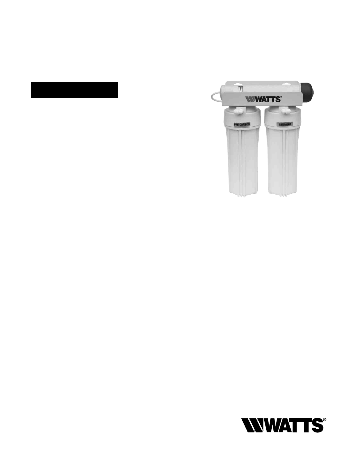
3-Stage Ultraviolet Systems
Model PWDWUV3
PURE WATER
Important
Please read the entire manual before proceeding with the
installation and startup. Your failure to follow any attached
instructions or operating parameters may lead to the product’s
failure.
Save manual for future reference.
This system has been designed to fit under most kitchen sinks.
DO NOT TOUCH THE UV LAMP OR QUARTZ TUBE AT ANY
TIME WITH BARE HANDS OR FINGERS.
Fingerprints or skin oils on the lamp and tube assembly may reduce
UV functionality.
This system requires a GFCI electrical outlet at point of
installation.
IOM-WQ-PWDWUV3
PWDWUV3
Table of Contents Pages
Mounting System Under Sink ..............................2
Installation of Faucet .....................................3
Adapt-A-Valve™ Installation ...............................4
Start up Instructions .....................................4
Recommended Replacement Schedule....................... 5
Filter Element Cartridges ..................................5
Filter Change ...........................................5
UV Lamp, Cap and Quartz Tube ............................5
Parts List ..............................................6
Limited Warranty ........................................8
Note: Do not use with water that is microbiologically unsafe or
of unknown quality without adequate disinfection before or after
the system. Systems certified for cyst reduction may be used
on disinfected waters that may contain filterable cysts.
Page 2
Introduction
Thank you for your purchase of a Watts Pure Water under counter filtration system with UV. With proper installation and mainte-
nance, this system will provide you with high-quality water for years
to come. All of Watts Pure Water water enhancement products are
rigorously tested by independent laboratories for safety and reliability.
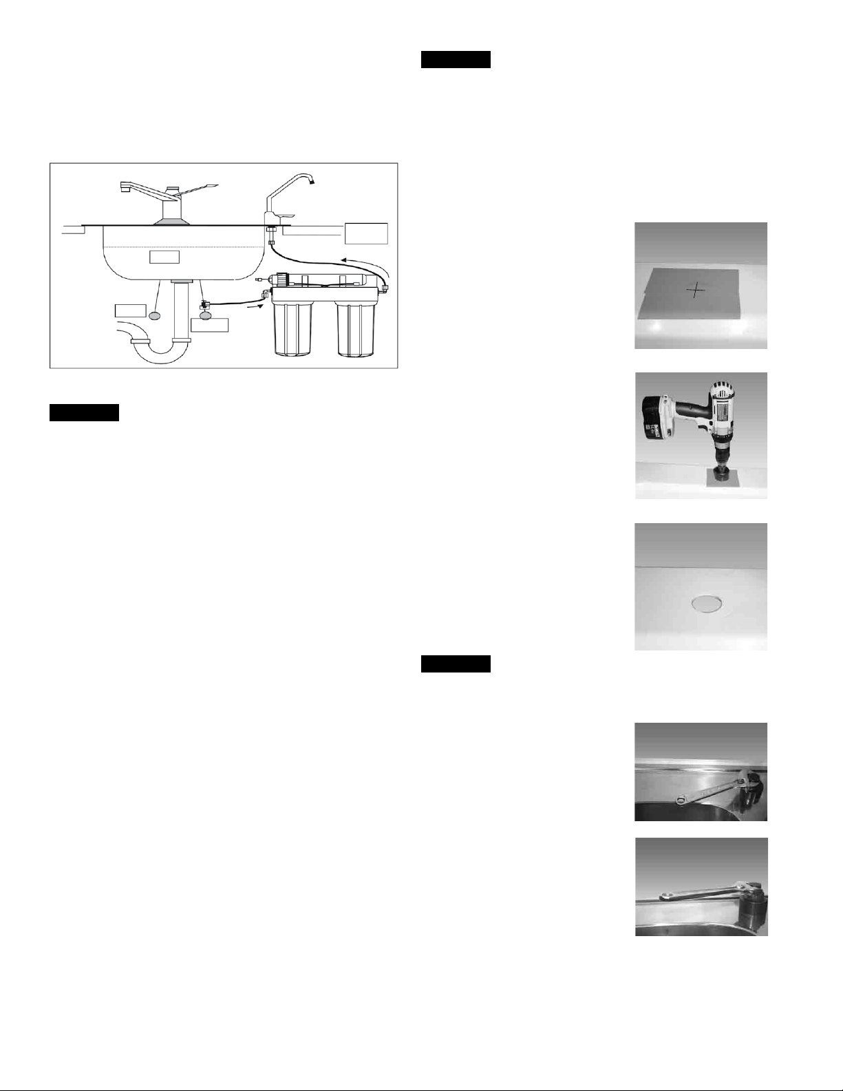
STEP 2
Drill a Hole for the Faucet in a Porcelain Sink
Note: Most sinks are predrilled with 1½" or 1¼" diameter hole
that you can use for your RO faucet. (If you are already using it
for a sprayer or soap dispenser, see Step 2).
Caution: Porcelain sinks are extremely hard and can crack or
chip easily.
Use extreme caution when drilling. Watts accepts no responsibility for damage resulting from the installation of faucet.
Counter
Top
Sink
Green Tubing
Hot
Cold
Blue Tubing
STEP 1
Mounting System Under Sink
Step A Locate a space under the sink that allows the unit to be
Step B Using the mounting hole on the bracket, mark the loca-
Step C Screw the (2) screws into the wall at the marked locations.
Step D The UV modules bracket is designed to be mounted
mounted close to the cold water supply and allows for
easy access during maintenance and filter changes. Allow
2" (50mm) clearance between the bottom of the filter
housing and the floor of the sink cabinet.
tion for the mounting screws on the cabinet wall under the
sink.
without removing the screws. Hang the UV module on the
screws using the mounting holes in the bracket.
Step A – Determine desired location for
Step B – Using a variable speed drill
Step C – Using a 1¼" hole saw, pro-
Step D – Make sure the surroundings
the RO faucet on your sink
and place a piece of masking
tape on over where the hole is
to be drilled. Mark the center
of the hole on the tape.
set on the slowest speed, drill
1
⁄8" pilot hole through both
a
porcelain and metal casing
of sink at the marked center
of the desired location. Use
lubricating oil or liquid soap to
keep the drill bit cool. (If drill
bit gets hot, it may cause the
porcelain to crack or chip).
ceed to drill the large hole.
Keep drill speed on the slowest speed and use lubricating
oil or liquid soap to keep the
hole saw cool during cutting.
of the sink are cooled before
mounting the faucet to the
sink after drilling and remove
all sharp edges.
OR
Punch a Hole for the Faucet in a Stainless
Steel Sink
Note: If mounting faucet to a Stainless
Steel Sink, you will need a 1¼" Hole
Punch. The faucet opening should be
centered between the back splash
and the edge of the sink, ideally on the
same side as the vertical drain pipe.
1
Step A – Drill a ¼" pilot hole. Use a
Hole Punch and an adjustable
wrench to punch the hole in the
sink. Change to the 1¼" Hole
Punch to enlarge the hole
The faucet can now be installed.
2
⁄2"
Page 3
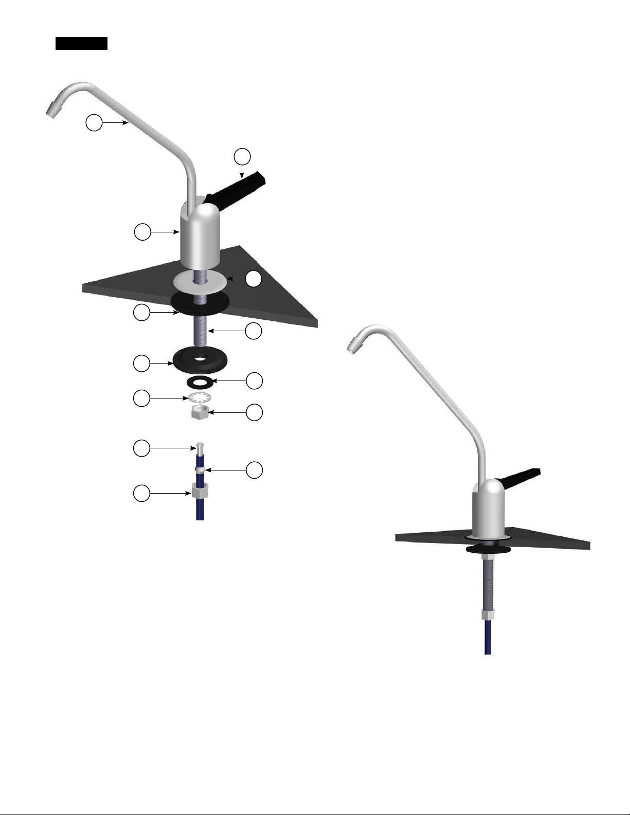
STEP 3
Non-Airgap Faucet Installation
Standard Faucet Installation
1
2
3
4
5
6
7
8
9
10
1. Long Reach Spout
2. Handle
3. Faucet Body
4. Escutcheon Plate
5. Black Rubber Washer
6. Stem Bolt
7. Black Locating Washer
8. Small Black Washer
9. Star Washer
10. Lock Nut
11. Tube Insert
12. Delrin Sleeve
13. Compression Nut
11
12
13
Figure A: List of Parts and Assembly in Exploded View
Gather and identify the faucet pieces.
Step A - Place the escutcheon chrome plate and the black rubber
washer on the faucet shank . (Parts found in faucet parts
bag) .
Step B - Insert the faucet shank through the hole in sink and let it
rest on the sink top .
Step C - From the underside of the sink, slide on the location wash-
er, star washer and Lock nut onto the stem bolt . Check for
orientation the tighten lock nut securely .
Step D - Locate the Blue tube from the Filters . Measure the tube
from the unit over to the faucet and cut it to the desired
length . Remove a the compression nut, plastic sleeve and
tube insert from the parts bag . To assemble, place the
compression nut on the tube first, then the sleeve (small
tapered end of the sleeve must point to the end of tube)
and then insert the tube insert all the way into the end of
the tube .
Figure B: Complete Assembly
Step E - Push the assembled blue tube into the faucet until it stops
. Slide compression nut and plastic sleeve down until you
can thread nut onto the faucet . Use a wrench to securely
tighten the compression nut while continuing to push the
tube into the faucet
3
Page 4
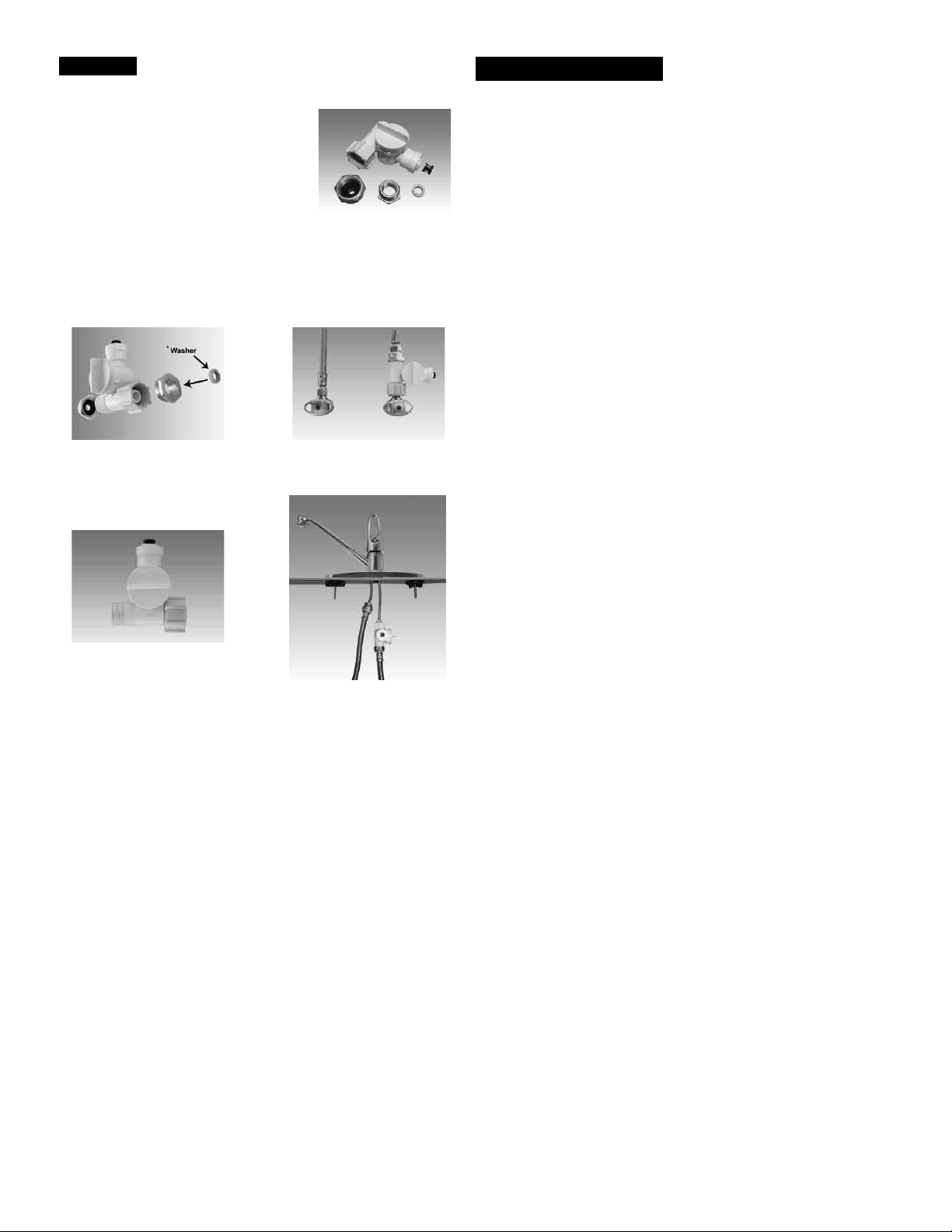
STEP 4
Adapt-A-Valve™ Installation
Verify contents prior to installation:
( 1 ) - Plastic Adapt-a-Valve™ & Black Collet
( 1 ) - Brass Adapter no washer
( 1 ) - Brass Adapter with black washer
( 1 ) - White rubber washer
Water supply line to the system must be from the cold water
supply line only. Hot water will severely damage your system.
WARNING: Do not use Teflon tape with the Adapt-A-Valve™.
For 3⁄8" Configuration
(With Brass Fittings)
* Insert White Washer
1
For
⁄2" Configuration
Hot
Supply
Cold
Supply
Start Up Instructions
Step A Lift black faucet handle up on faucet to start flow of water
through unit. Run 7 gallons of water through unit. Close
faucet.
Note: You may hear some noise as air is being purged from the
unit and the first few glasses of water through the unit may be
dark in color due to carbon fines.
Step B Check for leaks. If you have any leaks, shut off water sup-
ply to system, repair and restart unit.
Step C Connect plastic electrical connector from UV unit to the
plastic electrical connector from AC adapter.
Step D Plug adapter into GFCI electrical outlet. You will see a
pale blue light from the view port on the UV housing
body. The light indicates that the UV lamp is on and
working.
Please follow these guidelines:
Do not unplug UV unit from power supply. Turning system off
and on will shorten the life of the UV lamp. UV should be on
continuously for maximum effectiveness.
The system requires a warm-up period for proper operation.
Wait 20 minutes after plugging in the system before using water.
Water not drawn from unit for a period of time may have a
taste or odor and will be warm. To avoid this, allow water to run
through the system for one minute before using.
(Without Brass Fittings)
1
⁄2" Configuration
Step A - Turn off the cold water supply to the faucet by turning the
Step B - Open cold water sink faucet to relieve pressure.
Step C - Choosing the configuration that fits your plumbing, at-
angle stop valve completely off.
tach the Adapt-A-Valve™ as illustrated in the four photos
above.
Hot
Supply
Cold
Supply
4
Page 5

Recommended Replacement Schedule
Filter Element Cartridges
Watts recommends changing the filter element cartridges at least
every 6 months or 1350 gallons (5100 liters).
Stage 1: EDP# 7100331 (5-micron Sediment Filter)
Stage 2: EDP# 7100452 (1-micron Carbon Block)
UV-Lamp: Every 12 months or 9000 hours.
Cap & Quartz Tube: Every 24 months
Annual Filter Pack includes Sediment, Carbon Block and UV Lamp EDP# 7100112.
Filter Change
Step A Turn off incoming feed water supply to unit. Note: There
Step B Remove filter housing from lid by turning it to the left, as
Step C Remove used filter cartridges and discard. Discard the fil-
Step D Clean inside of filter housing with warm soapy water. Rinse
Step E Lubricate O-ring with water-soluble lubricant (i.e. K-Y
Do not over-tighten filter housing, overtightening may damage
O-ring(s), cause water leaks, or affect system performance.
Step F Seat O-ring in groove in filter housing.
Step G Insert new filter cartridges into filter housing.
Step H Screw filter housing onto lid (as shown in Figure D).
Step I Repeat Step 4: Start Up
will be water in the unit filter housing. Lift the faucet
handle to relieve the water pressure.
shown in Figure D.
ter gaskets. Note: Do not discard filter-housing O-ring.
the filter housing with clean warm water to remove soap.
®
or Silicone lubricant). Note: Do not use Petroleum
Jelly
based lubricants such as Vaseline
®
.
Ultra Violet Bulb Replacement
Warning: Do not touch UV Lamp or Quartz Tube with bare
fingers or hands. Fingerprints on the lamp or tube may reduce
lamp effectiveness. Handle with clean cloth or gloves.
Step A Turn off the incoming water supply.
Step B Unplug transformer from the power outlet and disconnect
Step C Remove UV lamp from housing by pulling on the UV wire
Note: DO NOT TOUCH NEW UV LAMP GLASS WITH BARE
HANDS, THIS WILL DAMAGE THE LAMP.
Step D Install new lamp by pushing it into the UV housing using
Step E Plug the transformer power cord connector into the UV
Turn on the incoming water supply and follow up with
Do not over-tighten filter housing, overtightening may damage
O-ring(s), cause water leaks, or affect system performance.
Step F Snap UV housing body back into single mounting clip.
Figure E: UV Tube Assembly
transformer wire harness from the UV lamp at the plastic
connector.
harness away from the UV housing. Use caution when
removing lamp not to break glass. Discard of old lamp.
the white end cap.
module wire harness connector and plug the transformer
into an electrical outlet. The white UV end cap will light up
when in service (Plugged in). If light does not come “on”
see troubleshooting on page 15.
page 4, Start Up Instructions.
1
Reconnect the
body.
⁄4" blue tubing back on to the UV housing
Figure D:
Filter Bowl Removal
to loosen to tighten
Replacement filters for this and many other filtration systems
can be purchased directly from Watts. Additionally, Watts sells
filtration and reverse osmosis systems suitable for almost any
individual or commercial application.
Replacement Filter Packs
MODEL FREQUENCY DESCRIPTION
PWMB10M5 6 Months 5-micron sediment filter
PWCB10LEAD 6 Months 1-micron carbon block filter
PWFPKUV3 Annual Includes all filters and
UV Replacement Lamp
Note: Water conditions may require more frequent cartridge replacement
UV Bulb
UV BULB
UV MODULE
UV Module
5
Page 6

Parts List
KITCHEN
SINK
TO
12
TRANSFORMER
CHROME
11
FAUCET
10
UV MODULE
9
13
1/4”
WHITE
TUBE
2
3
8
2 2
10
13
8
3
1/4”
WHITE
TUBE
14
1/4” BLUE TUBE
2
1/4” GREEN TUBE
15
FEED WATER
ADAPT-A-VALVE
1
MAIN WATER SUPPLY
SHUT-OFF VALVE
ITEM # DESCRIPTION
1 Adapt-A-Valve™
2 Elbow - 1/4" QC X 1/4" M
3 Filter Housing - Lid - 1/4" Ports
4 Filter Housing - Bowl - 10" - White
5 O-ring for Filter Housing
6 Sediment Filter
7 Lead, Cyst, VOC Carbon Block
8 Mounting Clip - UV Module
9 UV Module
10 Elbow - 1/4" QC X 1/4" Stem
11 Faucet - Chrome
12 Transformer
13 1/4" White Tubing
14 1/4" Blue Tubing
15 1/4" Green Tubing
5 5
6 7
4
SEDIMENT
FILTER
4
CARBON
BLOCK
6
Page 7

7
Page 8

LIMITED WARRANTY: Certain Watts Pure Water products come with a limited warranty from Watts Regulator Co. Other products may have no warranty or are covered by the original manufacturer’s
warranty only. For specic product warranty information, please visit www.watts.com or the published literature that comes with your product. Any remedies stated in such warranties are exclusive and
are the only remedies for breach of warranty. EXCEPT FOR THE APPLICABLE PRODUCT WARRANTY, IF ANY, WATTS MAKES NO OTHER WARRANTIES, EXPRESS OR IMPLIED. TO THE FULLEST EXTENT
PERMITTED BY APPLICABLE LAW, WATTS HEREBY SPECIFICALLY DISCLAIMS ALL OTHER WARRANTIES, EXPRESS OR IMPLIED, INCLUDING BUT NOT LIMITED TO THE IMPLIED WARRANTIES OF
MERCHANTABILITY AND FITNESS FOR A PARTICULAR PURPOSE, AND IN NO EVENT SHALL WATTS BE LIABLE, IN CONTRACT, TORT, STRICT LIABILITY OR UNDER ANY OTHER LEGAL THEORY, FOR
INCIDENTAL, INDIRECT, SPECIAL OR CONSEQUENTIAL DAMAGES, INCLUDING, WITHOUT LIMITATION, LOST PROFITS OR PROPERTY DAMAGE, REGARDLESS OF WHETHER IT WAS INFORMED ABOUT
THE POSSIBILITY OF SUCH DAMAGES.
A Watts Water Technologies Company
USA: North Andover, MA • Tel. (800) 224-1299 • www.watts.com
Canada: Burlington, ON • Tel. (888) 208-8927 • www.wattscanada.ca
IOM-WQ-PWDWUV3 1225 EDP# 2915880 © 2012 Watts
 Loading...