


 Loading...
M Series Reverse Osmosis Processor
With Built-in Pre-treatment and Membrane Flush
For Models:
M- 450
M-1000
M-2400
M-4800
M-9600
Installation, Operation
&
Maintenance Manual
Page 1 of 18

Before installing and/or operating Watts M-Series Reverse Osmosis system, read this manual completely. Keep this manual available for future reference. Further information is available by contacting your local Watts distributor. Phone: (623)505-1511
Pressure Tank
Atmospheric Tank
Page 2 of 18
TABLE OF CONTENTS
Specifications
Specifications Chart ……………………………… 4
Installation
Membrane installation ………………………………. 5 Inlet Connection ………………………………………. 6 Permeate Line Connection …………………..……. 7 Pressure Tank Connection ……………………..…. 8 Atmospheric Storage Tank ………………………… 9 Plumb to Drain ………………………………………. 10
Operation
Start Up …………………………………………………..11 Alarms …………………………………………………….12
Maintenance
Quarterly Maintenance ………………………………13
Annual Maintenance ………………………………….14
Warranty
Warranty ………………………………………………….15
Glossary of Terms …………………………..………. 17
Page 3 of 18

Specifications Complete System Packages
SPECIFICATIONS |
M-450 |
M-1000 |
M-2400 |
M-4800 |
M-9600 |
|
DRY WEIGHT lbs. |
300 |
310 |
350 |
650 |
750 |
|
|
|
|
|
|
|
|
WET WEIGHT lbs |
550 |
1700 |
1750 |
4000 |
4100 |
|
FEED WATER |
|
|
|
|
|
|
COLD/Temp |
½”/35°-70° |
½”/35°-70° |
½”/35°-70° |
¾”/35°-70° |
¾”/35°-70° |
|
HOT/ Temp |
½”/70°-140° |
½”/70°-140° |
½”/70°-140° |
¾”/70°-140° |
¾”/70°-140° |
|
FLOW RATE |
2 GPM |
4 GPM |
8 GPM |
12 GPM |
24 GPM |
|
MAX.HARDNESS |
17 Grains |
17 Grains |
17 Grains |
17 Grains |
17 Grains |
|
MAX. TDS |
2500 PPM |
2500 PPM |
2500 PPM |
2500 PPM |
2500 PPM |
|
MAX. IRON |
0.1 MGL |
0.1 MGL |
0.1 MGL |
0.1 MGL |
0.1 MGL |
|
MAX. PSIG |
80 |
80 |
80 |
80 |
80 |
|
MIM. PSIG |
25 |
25 |
25 |
25 |
25 |
|
DRAIN |
|
|
|
|
|
|
CONNECTION |
|
|
|
|
|
|
FLOOR SINK MIM. |
|
|
|
|
|
|
w/in 10 ft of |
1/ ¼” |
1/ ¼” |
1/ ¼” |
1/ ¼” |
1/ ¼” |
|
processor |
|
|
|
|
|
|
ELECTRICAL |
|
|
|
|
|
|
REQUIRMENTS |
VOLTS/AMPSVOLTS/AMPSVOLTS/AMPS VOLTS/AMPS VOLTS/AMPS |
|||||
RO PROCESSOR |
115/7.2 |
115/7.2 |
115/11.0 |
115/23 |
220/11.5 |
|
OPTIONAL 220V |
|
|
220/8.8 |
220/11.5 |
|
|
DELIVERY PUMP |
N/A |
115/8.8 |
115/12.4 |
115/12.4 |
115/12.4 |
|
KDF FILTER |
N/A |
N/A |
N/A |
115/2 |
115/2 |
|
Page 4 of 18
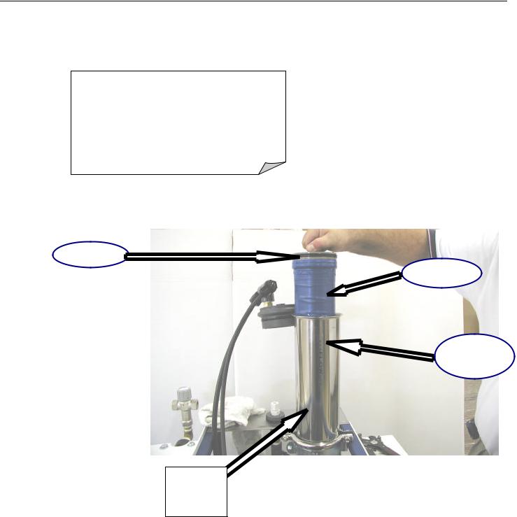
Membrane Installation
Note: All Membrane Vessels are clearly marked with flow direction.
Membrane “Brine Seal” is always facing the water entry to Vessel.
Brine Seal
Membrane
Membrane
Vessel
Flow
Direction
Marking
Page 5 of 18

Inlet Connection
HOT and/or COLD FEED WATER CONNECTION
Hard plumb Hot and/or Cold water connections into Blending Valve using (L) Copper Pipe. Refer to table below. Valve is marked with HOT and Cold connections.
Recommend installing Ball Valves just prior to the Blending Valve.
NOTE: Use only
Teflon tape on all
|
|
|
|
RO |
FEED WATER |
PIPE |
FLOW |
|
MIN/MAX |
SIZE |
RATE |
|
PSIG |
||
|
|
|
|
M-450 |
25/80 psig |
½” |
2 GPM |
|
|
|
|
M-100 |
25/80 psig |
½” |
4 GPM |
|
|
|
|
M-2400 |
25/80 psig |
½” |
8 GPM |
|
|
|
|
M-4800 |
25/80 psig |
1” |
12 GPM |
|
|
|
|
M-9600 |
25/80 psig |
1 ¼” |
24 GPM |
|
|
|
|
|
|
|
|
Page 6 of 18
Loading...