

Page 1
For Non-Health Hazard Applications
ES-LF007
Job Name
Job Location
Engineer
Approval
LEAD FREE
–––––––––––––––––––––––––––––––––––––––––––
–––––––––––––––––––––––––––––––––––––––––
–––––––––––––––––––––––––––––––––––––––––––––
–––––––––––––––––––––––––––––––––––––––––––––
*
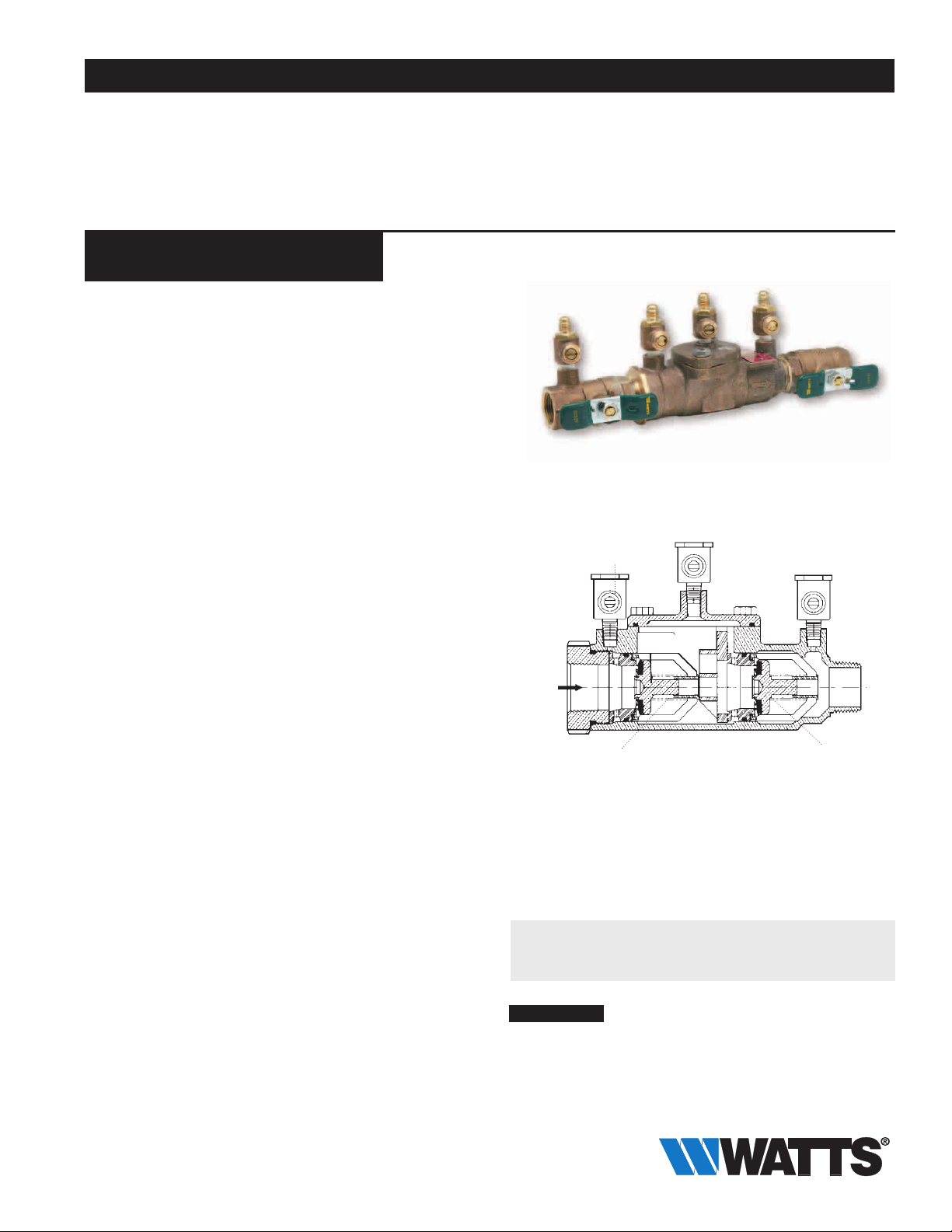
Series LF007
Double Check Valve Assemblies
Sizes: 1⁄2" – 3" (15 – 80mm)
Series LF007 Double Check Valve Assemblies shall be installed at
referenced cross-connections to prevent the backflow of polluted
water into the potable water supply. Only those cross-connections
identified by local inspection authorities as non-health hazard shall
be allowed the use of an approved double check valve assembly.
The LF007 features Lead Free* construction to comply with Lead
Free* installation requirements.
Check with local authority having jurisdiction regarding vertical orientation, frequency of testing or other installation requirements.
The valve shall meet the requirements of ASSE Std. 1015 and
AWWA Std. C510. Approved by the Foundation for CrossConnection Control and Hydraulic Research at the University
of Southern California.
Contractor
Approval
Contractor’s P.O. No.
Representative
3
––––––––––––––––––––––––––––––––––––––––––––
–––––––––––––––––––––––––––––––––––––––––––––
––––––––––––––––––––––––––––––––––––––––
⁄4" (20mm) LF007M3QT
Test Cocks
––––––––––––––––––––––––––––––––––
Features
•Ease of maintenance — only one cover
•Top entry
•Replaceable seats and seat discs
•Modular construction
•Compact design
• Lead Free* cast copper silicon alloy body construction —
•Fused epoxy coated cast iron body — 2
•Top mounted Lead Free* ball valve test cocks
•Low pressure drop
•No special tools required for servicing
•
1
⁄2" – 2" (15 – 50mm)
1
⁄2" – 1" (15 – 25mm) have tee handles
1
⁄2" – 3" (65 – 80mm)
Specifications
A Double Check Valve Assembly shall be installed at each noted
location. The assembly shall consist of two positive seating check
modules with captured springs and rubber seat discs. The check
module seats and seat discs shall be replaceable. Service of
all internal components shall be through a single access cover
secured with stainless steel bolts. The Double Check Valve
Assemblies shall be constructed using Lead Free* cast copper
silicon alloy. Lead Free* Double Check Valve Assemblies shall
comply with state codes and standards, where applicable, requiring reduced lead content. The assembly shall also include two
resilient seated isolation valves; four top mounted, resilient seated
test cocks. The assembly shall meet the requirements of ASSE
Std. 1015 and AWWA Std. C510. Approved by the Foundation for
Cross-Connection Control and Hydraulic Research at the University
of Southern California. Assembly shall be a Watts Series LF007.
First Check
Module Assembly
The LF007 Series features a modular design concept which facilitates
complete maintenance and assembly by retaining the spring load.
Second Check
Module Assembly
Now Available
WattsBox Insulated Enclosures.
For more information, send for literature ES-WB.
NOTICE
Inquire with governing authorities for local installation requirements
*The wetted surface of this product contacted by consumable
water contains less than 0.25% of lead by weight.
Watts product specifications in U.S. customary units and metric are approximate and are provided for reference only. For precise measurements,
please contact Watts Technical Service. Watts reserves the right to change or modify product design, construction, specifications, or materials without prior notice and without incurring any obligation to make such changes and modifications on Watts products previously or subsequently sold.
Page 2
Pressure — Temperature
1
⁄2" – 2" (15 – 50mm)
Temperature Range: 33°F – 180°F (0.5°C – 82°C).
Maximum Working Pressure: 175psi (12.1 bar).
1
2
⁄2" – 3" (65 – 80mm)
Temperature Range: 33˚F – 110°F (0.5˚C – 43°C) continuous,
140°F (60°C) intermittent.
Maximum Working Pressure: 175psi (12.1 bar).
Standards
ASSE Std. 1015, AWWA Std. C510
IAPMO PS31, CSA B64.5
Approvals
† ASSE, AWWA, IAPMO, CSA, UPC
s
Approved by the Foundation for Cross-Connection Control and
Hydraulic Research at the University of Southern California.
• Models with suffix LF and S are not listed.
u UL Classified (without shutoff valves only)
(20 – 50mm) (except 007M3LF)
u UL Classified with OSY gate valves
1
⁄2" and 3" horizontal only.)
(2
1
▼
⁄2" - 2" models Lead Free* with strainer
Horizontal and vertical “flow up" approval on all sizes
3
⁄4" – 2"
Models
Sizes:
1
⁄2" – 2" (15 – 50mm)
Suffix:
S - copper silicon alloy strainer
LF - without shutoff valves
Prefix:
U - Union connections
1
2
⁄2" – 3" (65 – 80mm)
Suffix:
NRS - non-rising stem resilient seated gate valves
OSY - UL/FM outside stem and yoke resilient seated gate valves
LF - without shutoff valves
QT-FDA - FDA epoxy coated quarter-turn ball valves
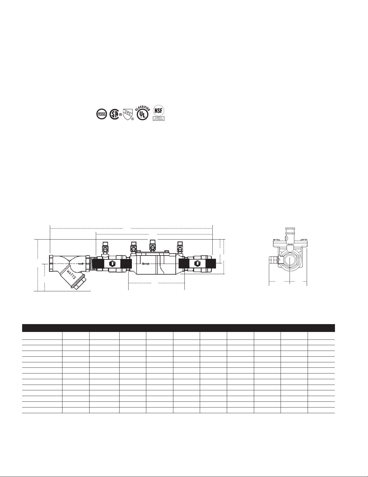
As
A
C
Bs
D
Subscript ‘S’ = strainer model
F
B
R
T
Dimensions – Weights
MODEL SIZE (DN) DIMENSIONS WEIGHT
A B C D F G R T
in. mm in. mm in. mm in. mm in. mm in. mm in. mm in. mm in. mm lbs. kgs.
†
s
▼
LF007QT
s
▼
LF007M3QT3⁄4 20 111⁄8 282 4 102 31⁄8 79 — — 63⁄16 157 37⁄16 87 21⁄8 5415⁄16 33 5 2.3
†
LF007M1QT 1 25 131⁄4 337 51⁄8 130 4 102 — — 71⁄2 191 33⁄8 85 111⁄16 43 111⁄16 43 12 5.4
s
▼
†
†
s
▼
LF007M2QT 11⁄4 32 163⁄8 416 5 127 35⁄16 84 — — 91⁄2 241 5 127 3 76 2 50 15 6.8
s
▼
LF007M2QT 11⁄2 40 163⁄4 425 47⁄8 124 31⁄2 89 — — 93⁄4 248 513⁄16 148 31⁄8 79 211⁄16 68 15.9 7.2
†
s
▼
LF007M1QT 2 50 191⁄2 495 61⁄4 159 4 102 — — 133⁄8 340 61⁄8 156 37⁄16 87 211⁄16 68 25.7 11.7
†
▼
LF007QT-S1⁄2 15 13 330 6 152 27⁄16 62 3 76 5 127 33⁄8 85 25⁄16 59 21⁄16 52 5.5 2.5
•
▼
LF007M3QT-S3⁄4 20 141⁄2 368 61⁄8 156 31⁄8 79 3 76 63⁄16 157 37⁄16 87 21⁄8 5415⁄16 33 6.7 3.1
•
▼
LF007M1QT-S 1 25 1715⁄16 157 73⁄4 197 4 102 31⁄4 83 71⁄2 191 33⁄8 85 111⁄16 43 111⁄16 43 14 6.4
•
▼
LF007M2QT-S 11⁄4 32 211⁄2 546 71⁄16 179 35⁄16 84 31⁄2 83 91⁄2 241 5 127 3 76 2 50 19 8.6
•
▼
LF007M2QT-S 11⁄2 40 251⁄16 637 71⁄16 179 31⁄2 89 33⁄4 95 93⁄4 248 513⁄16 148 31⁄8 79 211⁄16 68 19.6 8.9
•
▼
LF007M1QT-S 2 50 271⁄4 692 83⁄4 222 4 102 4 102 133⁄8 340 61⁄8 156 37⁄16 87 211⁄16 68 33.5 15.2
•
1
⁄2 15 10 254 45⁄8 117 27⁄16 62 — — 5 127 33⁄8 85 25⁄16 59 21⁄16 52 4.5 2
Page 3

Dimensions – Weights
Sizes: 21⁄2" – 3" (65 – 80mm)
9" (229mm)
N
E1
M
MODEL SIZE (DN) DIMENSIONS WEIGHT
A B E, E1 R
in. mm in. mm in. mm in. mm in. mm lbs. kgs.
A
LF007QT-FDA 21/2 65 331/8 841 63/8 162 91⁄16 230 83/4 222 155 70
s
LF007-NRS 21/2 65 331/8 841 93/8 238 91⁄16 230 83/4 222 155 70
su
LF007-OSY 21/2 65 331/8 841 163/8 416 91⁄16 230 83/4 222 158 72
LF007-QT-FDA 3 80 33
s
LF007-NRS 3 80 331/8 867 101/4 260 91⁄16 230 83/4 222 185 84
su
LF007-OSY 3 80 331/8 867 187⁄8 479 91⁄16 230 83/4 222 185 84
1
/8 867 63/8 162 91⁄16 230 83/4 222 155 70
E
C (open)
45⁄16" (109mm)
R
Strainer Dimensions
SIZE WEIGHT
in. mm in. mm in. mm lbs. kgs.
21⁄2 65 10 254 61⁄2 165 28 13
3 80 10
M N
1
⁄8 267 7 178 34 15
1" LFU007M1QT
Union Tailpiece
Union Nut
Sizes: 1⁄2" – 2" (15 – 50mm)
MODEL SIZE(DN) DIMENSIONS
in. mm in. mm
LFU007QT
LFU007M2QT
LFU007M2QT 1 25 16
LFU007M2QT 1
LFU007M2QT 1
LFU007M1QT 2 50 24
1
⁄2 15 1213⁄16 326
3
⁄4 20 1313⁄16 350
1
⁄4 32 203⁄4 527
1
⁄2 40 211⁄2 546
A
A
5
⁄8 422
1
⁄2 622
Union Tailpiece
Union Nut
Page 4

Capacity
As compiled from documented Foundation for Cross-Connection Control and
Hydraulic Research at the University of Southern California lab tests.
†† Typical maximum system flow rate (7.5 feet/sec., 2.3 meters/sec.)
** UL rated flow
1
Pressure Drop
3
Pressure Drop
1" (25mm)
Pressure Drop
⁄2" (15mm)
bars psi
.8 12
.7 10
.5 8
.4 6
.3 4
.1 2
0 0
0 2 4 6 8 10 12 gpm
0 7.6 15.2 22.8 30.4 38 45.6 lpm
5 7.5 10 fps
1.5 2.5 3.0 mps
⁄4" (20mm)
bars psi
1.5 22
1.2 18
.96 14
.69 10
.41 6
.14 2
0 5 10 15 20 25 30 35 40 45 50 gpm
0 19 38 57 76 95 114 133 152 171 190 lpm
7.5 15 lps
2.3 4.6 mps
bars psi
1.1 16
.8 12
.7 10
.5 8
.4 6
.3 4
.1 2
0 5 10 15 20 25 30 35 40 45 50 55 60 gpm
0 19 38 57 76 95 114 133 152 171 190 209 228 lpm
5 7.5 10 15 fps
1.5 2.3 3.0 4.6 mps
††
††
††
Flow
Flow
Flow
1
1
bars psi
.8 12
.7 10
.5 8
.4 6
.3 4
.1 2
Pressure Drop
0 0
⁄2" (40mm)
††
0 10 20 30 40 50 60 70 80 90 100 110 120 gpm
0 38 76 114 152 190 228 66 304 342 380 418 456 lpm
5 7.5 10 15 fps
1.5 2.5 3.0 4.5 mps
Flow
2" (50mm)
bars psi
.8 12
.7 10
.5 8
.4 6
.3 4
.1 2
0 0
Pressure Drop
0 25 50 75 100 125 150 175 200 gpm
0 95 190 285 380 475 570 665 760 lpm
5 7.5 10 15 fps
1.5 2.3 3.0 4.6 mps
††
Flow
1
2
bars psi
.7 10
.5 8
.4 6
.3 4
Pressure Drop
.1 2
0 0
⁄2" (65mm)
††
0 25 50 75 100 125 150 175 200 225 250 gpm
0 95 190 285 380 475 570 665 760 855 950 lpm
5 7.5 10 15 fps
1.5 2.3 3.0 4.6 mps
Flow
**
11⁄4" (32mm)
bars psi
1 14
.8 12
.7 10
.5 8
.4 6
.3 4
Pressure Drop
.1 2
0 0
0 10 20 30 40 50 60 70 80 90 100 110 120 gpm
0 38 76 114 152 190 228 266 304 342 380 418 456 lpm
5 7.5 10 15 fps
1.5 2.3 3.0 4.6 mps
††
3" (80mm)
bars psi
.7 10
.5 8
.4 6
.3 4
.1 2
0 0
0 25 50 75 100 125 150 175 200 225 250 275 300 325 gpm
Pressure Drop
0 95 190 285 380 475 570 665 760 855 950 1045 1140 1235 lpm
5 7.5 10 fps
1.5 2.3 3.0 mps
††
Flow
**
Flow
A Watts Water Technologies Company
USA: Tel: (978) 688-1811 • Fax: (978) 794-1848 • www.watts.com
Canada: Tel: (905) 332-4090 • Fax: (905) 332-7068 • www.watts.ca
ES-LF007 1325 © 2013 Watts
 Loading...