

Page 1
Installation, Operation
and Maintenance Manual
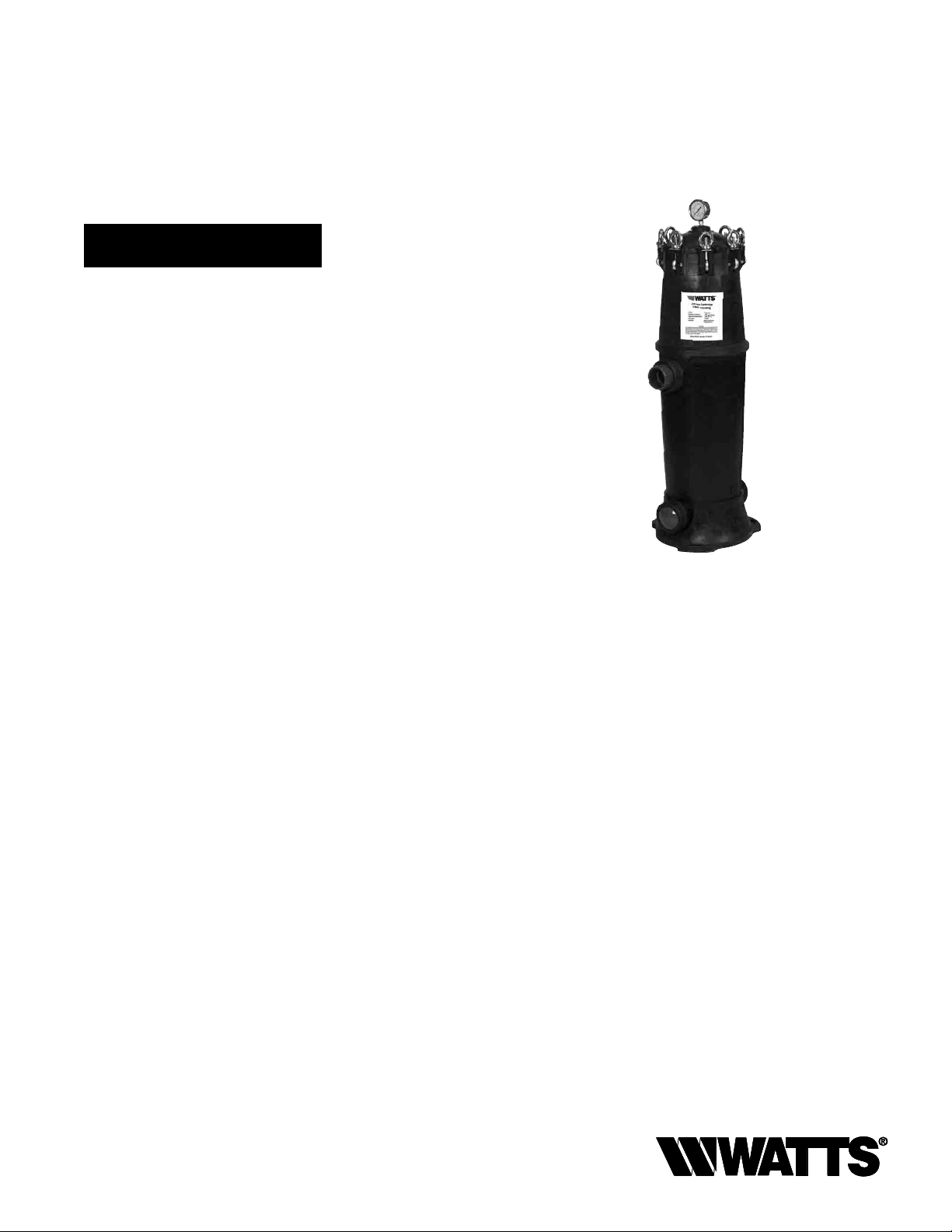
Jumbo Cartridge Filter Housing
Model PWWJCHSG
PURE WATER
Important
Please read the entire manual before proceeding with the
installation and startup. Your failure to follow any attached
instructions or operating parameters may lead to the product’s
failure.
Save manual for future reference.
IOM-WQ-PWWJCHSG
PWWJCHSG
Table of Contents
Specifications ..........................................2
Installation Procedures ...................................2
Cartridge Installation .....................................2
Routine Cartridge Replacement ............................3
Parts List ..............................................3
Limited Warranty .......................................4
Note: Do not use with water that is microbiologically unsafe or
of unknown quality without adequate disinfection before or after
the system.
Page 2

Introduction
Prior to shipment, Watts®Jumbo Cartridge Filter Housing have been
inspected to assure they are free from manufacturing defects. Before
installation, however, please check the lid's O-ring to ensure it is in
place and note the inlet and outlet labels for proper pipe connections. (See drawing on Page 3.)
Note: Filter housing has two outlets to allow for same direction piping. A plug has been provided to use to close off the
pipe fitting not used.
Specifications
Material, body & cartridge end caps Glass reinforced PP
Brass reinforced gauge port
Material, swing bolts 304SS
O-ring EPDM
Lid closure Swing bolt
Pipe fittings (One inlet and two outlets) PVC 2" SLIP Female PVC
Drain
Overall height 42.7"
Width 15.4"
Maximum flow rate
(with pleated cartridges 5 micron and up)
Maximum flow rate (with depth cartridges) 100 GPM (22.7M3/hr)
Maximum flow rate
(with pleated 1 micron absolute cartridge)
Maximum flow rate (with carbon cartridge) 15GPM (3.4 M3/hr)
Maximum working pressure 125psi (8.75 bar)
Maximum temperature 125°F (52°C) @ 80psi
Cartridge change-out, sediment 30psi differential (max.)
Cartridge change-out, carbon Every 6-12 months*
Shipping weight 47 lbs.
Carton dimensions (L x W x D) 16" x 16" x 40"
* Depending on chlorine level and water usage.
Note: Flow rates are for guidelines only, and they are based
on micron rating, solids content and other factors. Users are to
determine the best flow rate for their application based on these
factors.
1
⁄4" FNPT
1
⁄2" FNPS with drain plug
150 GPM (34M3/hr)
50 GPM (11.3M3/hr)
Installation Procedures
Install filter housing using the appropriate size pipe. (Pipe fittings are
2" slip). Follow the PVC glue and primer manufacturer’s instructions
when making all solvent weld connections. Be sure to install shutoff
valves before and after the filter housing and on any drain connections, which are to be installed. A
of the filter's lid, and a pressure gauge has been provided. Locate
this gauge (in carton) and install it in gauge port using Teflon tape. A
second gauge may be installed; downstream of the filter (in the pipe
line) to indicate pressure differential and help you determine when
cartridge replacement may be necessary.
1
⁄4" FNPT port is located on top
Cartridge Installation
To remove the filter's lid when the filter is under pressure, turn off
the inlet and outlet valves, press pressure relief button to relieve
pressure. Then remove eyebolts, lid, and notice the way the O-ring
is positioned. From time to time, this O-ring may be lubricated with
non-petroleum based lubricant for optimum performance. Filter
cartridges have double O-rings on the male ends to provide superior
sealing. From time to time, these O-rings may be lubricated with
non-petroleum based lubricant for better results. The other end
of the cartridge is closed, and a handle is part of the end cap for
convenience.
Filter cartridges have locking tabs on the male ends of the cartridges
to lock the cartridges in place. For proper installation, insert filter
cartridge into the cartridge adapter, which is located at the bottom of
the filter housing. Once the cartridge is pushed down all the way, rotate cartridge clockwise to engage the locking tabs until the cartridge
has been locked in place.
To remove cartridge, rotate cartridge counterclockwise and pull
upward.
Vent and Pressure Gauge
A 1⁄4" FNPT port and pressure gauge has been installed in the filter's
lid to indicate working pressure. A second gauge may be installed,
downstream of the filter in the pipe line to indicate pressure differential and help determine when cartridge replacement may be
necessary.
Initial Start Up
Once the piping procedures are completed, shutoff valves have been
installed and the cartridge has been inserted and locked in place,
open outlet completely, start up pump and open inlet valve slowly to
check for leaks. If leaks occur, shut off pump, close inlet and outlet
valves, release pressure by pressing pressure release button, remove
lid and check the O-ring to be sure it is properly seated.
Caution
Do not attempt to remove lid without relieving pressure. To open
lid, close shutoff valves before and after filter, press pressure relief
button to relieve pressure. Once pressure has been relieved, remove
eyebolts and lid. To start up filter, replace lid, tighten eyebolts, and
open shutoff valves slowly to check for leaks. If lid O-ring does not
seat properly, close shutoff valves, relieve pressure, open lid, apply a
small amount of non-petroleum based lubricant to the O-ring to help
it seal, reposition O-ring and close lid.
Do not operate filter above 125psi (8.8 bar). In installations
where pressure is above 100psi (6.9 bar), install a pressure
release valve to release pressure at 125psi (8.8 bar) or less.
2
Page 3

Routine Cartridge Replacement
1. Close inlet valve.
2. Close outlet valve.
3. Open valve on drain, if a drainpipe has been installed.
4. Press pressure relief button to relieve pressure.
5. Remove lid after pressure has been relieved.
6. Rotate cartridge counterclockwise and pull upward. Remove the
cartridge.
7. Install new cartridge. Push downward and rotate clockwise to
engage locking tabs lubricating O-rings if necessary.
8. Check lid O-ring to ensure it is properly seated. Lubricate if
necessary.
9. Replace lid.
10. Replace eyebolts and tighten. (Hand tight is sufficient.)
11. Close valve on drain if a drainpipe was installed.
12. Open outlet pipe completely.
13. Open inlet pipe slowly to check for leaks.
14. Vent filter to dispel air by depressing pressure relief button. Be
careful when relieving pressure or dispelling air if high temperature water is being filtered.
Note: If leaks occur, close the inlet and outlet pipes and follow procedures previously described under “Caution” section above.
Parts List
Pleated Cartridges
Ideal for more critical applications, offering greater efficiency,
more surface area for greater throughput and reduced cost.
MODEL NUMBER MEDIA TYPE MICRON RATING PER CASE
PWWJCP1AB 1 1 Absolute 1
PWWJCP1 1 1 1
PWWJCP5 1 5 1
PWWJCP20 1 20 1
PWWJCP50 1 50 1
PWWJCM150 1 150 1
Note: 5, 20, 50 and 150 micron cartridges are cleanable and reusable to reduce
costs.
Depth Cartridges
Melt blown Polypropylene cartridges are recommended when
depth filtration is necessary for the reduction of soft particulate.
MODEL NUMBER MEDIA TYPE MICRON RATING PER CASE
PWWJCMB1 1 1 1
PWWJCMB5 1 5 1
PWWJCMB20 1 20 1
PWWJCMB50 1 50 1
Activated Carbon Cartridge
Ideal for whole house filtration to reduce chlorine, taste, odors
and sediment.
MODEL NUMBER MAX. FLOW CAPACITY CHLORINE
REDUCTION
PWWJCAC5 15 GPM 140,000 Gals. 90%
Note: We build filtration systems, or they may be installed on site.
For more information please inquire.
Note: Two outlets are provided so outlet piping may be directed to either direction. A plug is provided to close off the outlet
not being used.
ITEM # DESCRIPTION
1 ¼" Pressure Gauge
2, 6 & 7 Pressure relief assembly includes cap, spring and stem
2 Pressure release button
3 Wing Nut
4 Washer for lid closure
5 Lid with brass reinforced gauge port
5A Lid without brass reinforced gauge port
6 Pressure relief spring
7 Lock pin with O-ring
8 O-ring for lid closure, EPDM
9 Stud for eye bolt
10 Eyebolt
11 Adapter 2" PVC
12 Drain plug ½" NPS without O-ring
13 Drain plug O-ring
14 Coupler
15 Coupler O-ring
16 Plug for second outlet
17 Nut for plumbing adapter
18 Base
19 Mounting Bolts
3
Page 4

Pressure Drop
1 Abs.
15
10
5
Pressure Drop (psi)
0 25 50 100 125 150
Flow (GPM)
1 µm
5 µm
20 µm
50 µm
150 µm
Low Pressure Drop
Watts® Jumbo Cartridge Housings are designed to minimize pressure
drop, by using 2" pipe fittings and large diameter center tubes.
(See chart above for pressure drop data using pleated cartridges.)
LIMITED WARRANTY: Certain Watts Pure Water products come with a limited warranty from Watts Regulator Co. Other products may have no warranty or are covered by the original manufacturer’s
warranty only. For specic product warranty information, please visit www.watts.com or the published literature that comes with your product. Any remedies stated in such warranties are exclusive and
are the only remedies for breach of warranty. EXCEPT FOR THE APPLICABLE PRODUCT WARRANTY, IF ANY, WATTS MAKES NO OTHER WARRANTIES, EXPRESS OR IMPLIED. TO THE FULLEST EXTENT
PERMITTED BY APPLICABLE LAW, WATTS HEREBY SPECIFICALLY DISCLAIMS ALL OTHER WARRANTIES, EXPRESS OR IMPLIED, INCLUDING BUT NOT LIMITED TO THE IMPLIED WARRANTIES OF
MERCHANTABILITY AND FITNESS FOR A PARTICULAR PURPOSE, AND IN NO EVENT SHALL WATTS BE LIABLE, IN CONTRACT, TORT, STRICT LIABILITY OR UNDER ANY OTHER LEGAL THEORY, FOR
INCIDENTAL, INDIRECT, SPECIAL OR CONSEQUENTIAL DAMAGES, INCLUDING, WITHOUT LIMITATION, LOST PROFITS OR PROPERTY DAMAGE, REGARDLESS OF WHETHER IT WAS INFORMED ABOUT
THE POSSIBILITY OF SUCH DAMAGES.
A Watts Water Technologies Company
IOM-WQ-PWWJCHSG
1225 EDP# 2915871 © 2012 Watts
USA: Tel. (800) 224-1299 • www.watts.com
Canada: Tel. (888) 208-8927 • www.watts.ca
 Loading...