

Page 1

19. Power and Switchable
Comm Board
WCC III
19. Power and Switchable
Comm Board
Page 2

T ABLE OF CONTENTS
SECTION 19: POWER AND
SWITCHABLE COMM BO ARD
Overview ...................................................19-1
Power and Switchable RS-485 Communications
Board Application Drawing .................................................19-2
WCC III System Overview .........................19-3
Diagram of WCC III System ......................19-4
WCC III - MCD Typical System
Architecture ..............................................19-5
Typical WCC III System Communications
Wiring – Not the recommended and
preferred way ............................................19-6
Typical WCC III System Communications
Wiring – The recommended and
preferred way ............................................19-7
Page 3
19. POWER AND SWITCHABLE COMM BOARD
GND
24VAC
GND
24VAC
24VAC
24VAC
24VAC
24VAC
24VAC
24VAC
24VAC
GND
GND
GND
GND
GND
GND
GND
24VACGND
24VAC
GND
485 COMM IN
POWER IN
POWER & SWITCHABLE COMM
WATTMAS TER CONTROLS IN C.
YS102224 REV 0
MADE IN USA JRN
T
R
SH
TSHR
R
SH
T
TSHR TSHR TSHR TSHR TSHR TSHR TSHR TSHR
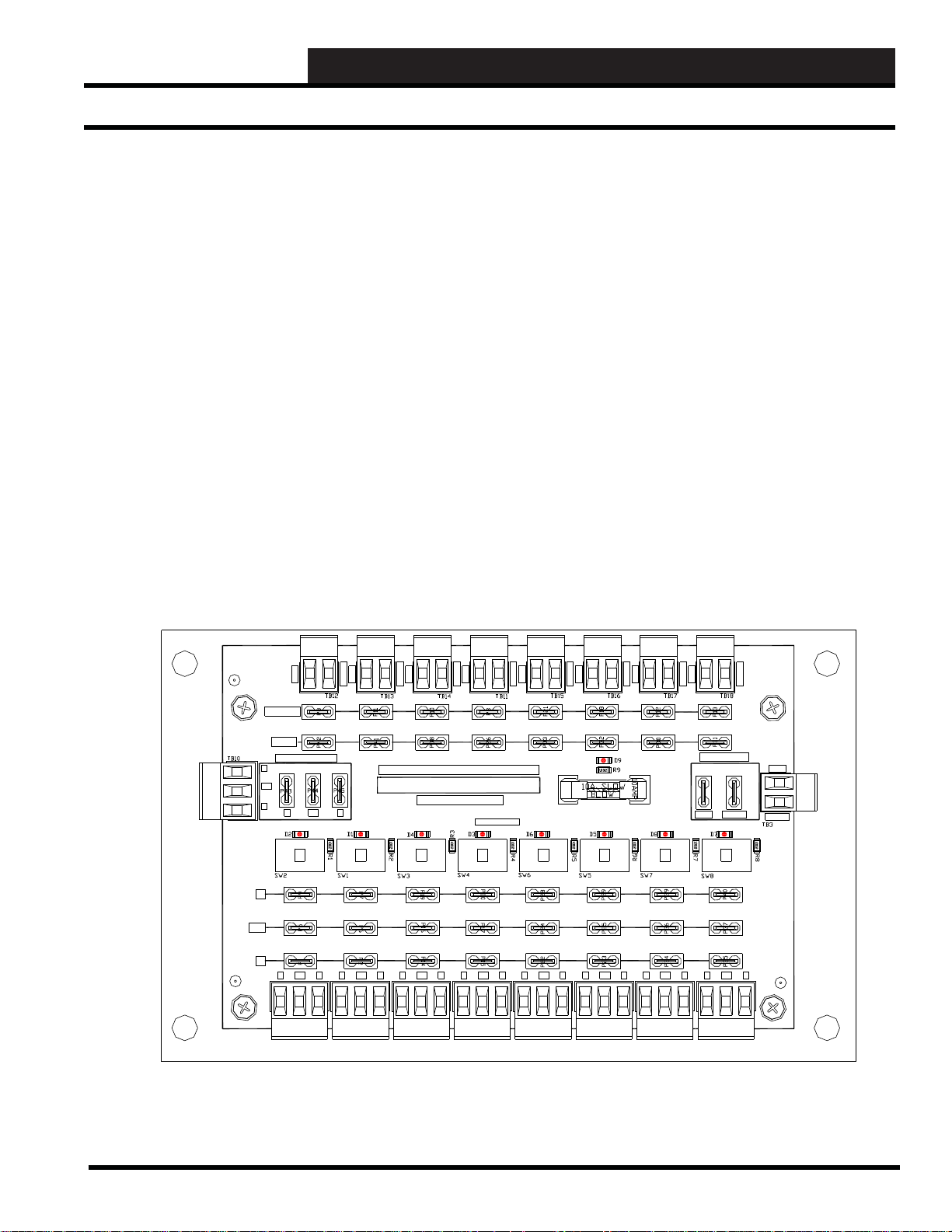
Introduction
SECTION 19:
POWER AND SWIT CHABLE COMM
BOARD
__________________________________________
The Power and Switchable Comm Board was designed to
be used as a central connection point for the SAT III RS-485
communications loop.
Eight push-button switches are provided to disconnect the RS-485
communications loop for troubleshooting purposes.
The RS-485 communication connections are as follows: “R”
to “R”, “T” to “T”, and “SHLD” to “SHLD” or “SH”. These
connections are from Satellite-type controller to Satellite-type
controller. These eight push-button switches only disconnect
the RS-485 communications loop. THEY DO NOT SWITCH
POWER ON/OFF .
This Power and Switchable Comm Board may also be used as a
central connection point for the SA T 3C/D/F TUC communications
loop.
The RS-485 communication connections are as follows: “R” to
“R”, “T” to “T”, and “SHLD” to “SHLD” or “SH”. This RS-485
communications connection is from TUC Controller to TUC
Controller. But, on the SAT 3C/D/F Controller, the TUC “R”
connection must be wired to the SAT 3C/D/F “T” connection, and
the SAT 3C/D/F Controller “R” connection must be wired to the
TUC “T” connection. This is a carry over connection method from
the old SAT 2C/D Controller.
The WCC III Power and Switchable Comm Board has 9 status
lights. The functions of these lights or LEDs are listed below:
• D9 - This LED will be lit any time power is applied to
the WCC III Power and Switchable Comm Board.
•
SW1 to SW8 - These eight LEDs will be lit any time a
corresponding push button is depressed to connect
the RS-485 communications to the corresponding eight
communication ports.
Figure 19-1: The Power and Switchable Comm Board
WCC III Technical Guide
1
19-1
Page 4

19. POWER AND SWITCHABLE COMM BOARD
Pow er and Switchable RS-485 Communications Board
19-2
Figure 19-2: The Power and Switchable RS-485 Communications Board Application Drawing
WCC III Technical Guide
Page 5

19. POWER AND SWITCHABLE COMM BOARD
WCC III System Overview
Optional V-OUTBoard
( 8 RELAYOUTS)
(2 PER SATIII)
OE210
TYPICAL
SENSOR
(X8)
ON/OFF RELAY
PUMPS, LIGHTS,
ETC.
16 OUTPUTS
PER SATIII
WCC II TO WCC III
CONNECTION
TO OLD WCC II
MANCHESTER
COMM LOOP
GLOBAL BRIDGE
BUILDING # 2
BB
PL102335
RS-485 TO FIBER
OPTIC ADAPTER
USUALLYONE
OR TWO PER
FLOOR
SATCOMM LOOP
Optional B-INPUT Board
( 8 BINARY INPUTS)
(2 PER SATIII)
HSS PORT
HSS PORT
+V
ATI
ON OFF
BATTON/ OFF
STATUS
PULSE INPUT
L
OPTION 3
SATIII
SATREC
O
OPTION 2
PROGRAMMABLE CONTROLLER
OPTION 1
A
SATXMIT
LOCALSETDISABLE
D
LOCALSET
TEST
HSS REC
ANALOG INPUT
GND
JUMPER SELECTION
HSS XMIT
ON OFF
THERM
0TO 1V
0 - 10V
LOCALSET
L16
0 - 5V
INPUT
V
L15
0-15VDC
OUTPUT
MIN LOAD
IS 1K OHM
RESISTIVE
VDC ONLY
2134
5678
CHANNEL
2134
5678
EACH CONTACT
IS RATED FOR
24VAC ORVDC
@ .5AMPMAX
GLOBALBRIDGE
PROGRAM SOCKET
WATTMASTER CONTROLS INC
YS102210 REV 1
MADE IN USA
ADDRESS
R/T
PCF8583
C
24C128
SATII
POWER
SATII STAT
LT1785
COMM
24VAC
GND
UP TO 60 TOTAL SAT III
OR SAT3C/D/F/P PER LOOP.
THERE ARE 4 POSSIBLE
SATIII RS485
COMMUNICATIONS LOOPS
(UP TO 239 SAT III MAXIMUM)
FIBER OPTIC LINES
MAXIMUM OF 2.5 MILES
(USES "ST" CONNECTORS)
0 - 1V
L14
STATUS 1
OUT
BINARY
L13
THERM
L12
0TO 5V
0 - 10V
INPUTS
STATUS 2
L11
0 - 5V
INPUT
L10
0 - 1V
L9
STATUS 3
THERM
0TO 10V
0 - 10V
INPUT
0 - 5V
ON OFF
0 - 1V
L8
CH
THERM
L7
0 - 10V
L6
THERMISTOR
1
BINARY
0 - 5V
L5
INPUT
0 - 1V
L4
INPUTS
L3
2
THERM
L2
H
0 - 10V
L1
CURRENT
3
0 - 5V
INPUT
0 - 1V
4
ON OFF
A4TO 20 mASENSORWILLREQUIREA
50 OHM LOAD RESISTORWHEN SETFOR
COM
A1VOLTINPUT, ORA250 OHM LOAD
128
5
RESISTORWHEN SETFORA5VOLTINPUT.
64
A2WIRE ROOM SENSORWILLREQUIRE
32
6
A300 OHM LOAD RESISTORWHEN SET
16
FORA1VOLTINPUT.
8
C
A3WIRE ROOM SENSORWILLNOT
4
7
REQUIREALOAD RESISTORWHEN SET
2
FORA1VOLTINPUT.
SATADDRESS
1
8
WattMaster Controls Inc.
SHLD
COMMT
EEPROM
485
COMM R
DRIVER
SATIII
VBAT
CHASSIS GND
SATCOMM LOOP
0-15VDC
OUTPUT
MIN LOAD
IS 1K OHM
RESISTIVE
PL102224
POWER AND
SWITCHABLE COMM
VDC ONLY
EACH CONTACT
IS RATED FOR
24VAC ORVDC
@ .5AMPMAX
MULTIPLE PULSE
INPUTS FROM
POWER METERS
SINGLE PULSE
INPUT FROM
POWER METER
2134
CHANNEL
2134
OE421- SATIII
CONTROLLER
+V
ATI
L
O
A
D
GND
V
0-15VDC
OUTPUT
OUT
MIN LOAD
IS 1K OHM
RESISTIVE
VDC ONLY
2134
5678
CHANNEL
2134
5678
H
COM
C
EACH CONTACT
IS RATED FOR
24VAC ORVDC
@ .5AMPMAX
TO THE ISP
(INTERNET SERVICE PROVIDER)
CONNECTION TO THE INTERNET
(BY OTHERS)
PL102335
RS-485 TO FIBER
OPTIC ADAPTER
USED IN MULTIPLES
OF TWO
OE421- SATIII
CONTROLLER
+V
ATI
ON OFF
BATTON/ OFF
STATUS
PULSE INPUT
L
OPTION 3
SATIII
SATREC
O
OPTION 2
PROGRAMMABLE CONTROLLER
OPTION 1
A
SATXMIT
LOCALSETDISABLE
D
LOCALSET
TEST
HSS REC
ANALOG INPUT
GND
JUMPER SELECTION
HSS XMIT
ON OFF
THERM
0TO 1V
0 - 10V
LOCALSET
L16
0 - 5V
INPUT
V
L15
0 - 1V
L14
STATUS 1
OUT
BINARY
L13
THERM
L12
0TO 5V
0 - 10V
INPUTS
STATUS 2
L11
0 - 5V
INPUT
L10
5678
5678
0 - 1V
L9
STATUS 3
THERM
0TO 10V
0 - 10V
INPUT
0 - 5V
ON OFF
0 - 1V
L8
CH
THERM
L7
0 - 10V
L6
THERMISTOR
1
BINARY
0 - 5V
L5
INPUT
0 - 1V
L4
INPUTS
L3
2
THERM
L2
H
0 - 10V
L1
CURRENT
3
0 - 5V
INPUT
0 - 1V
4
A4TO 20 mASENSORWILLREQUIREA
ON OFF
50 OHM LOAD RESISTORWHEN SETFOR
COM
A1VOLTINPUT, ORA250 OHM LOAD
128
5
RESISTORWHEN SETFORA5VOLTINPUT.
64
A2WIRE ROOM SENSORWILLREQUIRE
32
6
A300 OHM LOAD RESISTORWHEN SET
16
FORA1VOLTINPUT.
8
C
A3WIRE ROOM SENSORWILLNOT
4
7
REQUIREALOAD RESISTORWHEN SET
2
FORA1VOLTINPUT.
SATADDRESS
1
8
WattMaster Controls Inc.
ON OFF
BATTON/ OFF
PULSE INPUT
OPTION 3
OPTION 2
OPTION 1
LOCALSETDISABLE
LOCALSET
TEST
ON OFF
L16
L15
L14
BINARY
L13
L12
INPUTS
L11
L10
L9
ON OFF
L8
L7
L6
BINARY
L5
L4
INPUTS
L3
L2
L1
ON OFF
128
64
32
16
8
4
2
SATADDRESS
1
OE455-P
SAT3P
CONTROLLER
PULSE INPUTS
P1
P2
P3
P4
P5
P6
P7
P8
GND
GND
OPTIONS
SEL
TEST
LOCAL
LDIS
OPT1
OPT2
OPT3
POWER
24 VAC
GND
STATUS
SATIII
SATREC
PROGRAMMABLE CONTROLLER
SATXMIT
HSS REC
ANALOG INPUT
JUMPER SELECTION
HSS XMIT
THERM
0TO 1V
0 - 10V
LOCALSET
0 - 5V
INPUT
0 - 1V
STATUS 1
THERM
0TO 5V
0 - 10V
STATUS 2
0 - 5V
INPUT
0 - 1V
STATUS 3
THERM
0TO 10V
0 - 10V
INPUT
0 - 5V
0 - 1V
CH
THERM
0 - 10V
THERMISTOR
1
0 - 5V
INPUT
0 - 1V
2
THERM
0 - 10V
CURRENT
3
0 - 5V
INPUT
0 - 1V
4
A4TO 20 mASENSORWILLREQUIREA
50 OHM LOAD RESISTORWHEN SETFOR
A1VOLTINPUT, ORA250 OHM LOAD
5
RESISTORWHEN SETFORA5VOLTINPUT.
A2WIRE ROOM SENSORWILLREQUIRE
6
A300 OHM LOAD RESISTORWHEN SET
FORA1VOLTINPUT.
A3WIRE ROOM SENSORWILLNOT
7
REQUIREALOAD RESISTORWHEN SET
FORA1VOLTINPUT.
8
WattMaster Controls Inc.
HIGH SPEED CABLE
MODEM / ROUTER
0-15VDC
OUTPUT
MIN LOAD
IS 1K OHM
RESISTIVE
VDC ONLY
2134
CHANNEL
2134
EACH CONTACT
IS RATED FOR
24VAC ORVDC
@ .5AMPMAX
SATIII-P
PULSE METER BOARD
ATTMASTER CONTROLS
YS102268 REV0
MADE IN USA
PULSE 1
PULSE 2
TOTALWIRING FOR EACH INPUTNOT
PULSE 3
TO EXCEED 100 FEET.
PULSE 4
USE 18 GAUGETWISTED PAIR WITH
SHIELD FOR EACH PULSE METER
PULSE 5
CONNECTION.
PULSE 6
CONNECTTHE SHIELD WIRETO GND.
PULSE 7
PULSE 8
STATREC
“P”MODEADDRESSING NOTES
STATXMIT
SATIIIADDRESSING STARTSAT
ADDRESS NUMBER 8.
LOCALSET
EACH "P" MODE SATIIITAKES UP
STATUS
(8) SATIII LOGICALADDRESSES.
THEREARE ONLY(8) USEDACTIVE
INPUTS PER SAT3P.
ADDRESS
ANALOG INPUT#1 (PULSE INPUT#1)
ON EACH SATIIIADDRESS ISACTIVE.
ADD
ALLOTHER INPUTSAND OUTPUTS ON
1
THE SAT3PARE NOTFUNCTIONAL.
2
4
8
16
32
64
128
COMM
R
SH
T
OE454 / O 455 / OE456E
OE421- SATIII
CONTROLLER
+V
ATI
ON OFF
BATTON/ OFF
PULSE INPUT
L
OPTION 3
O
OPTION 2
OPTION 1
A
LOCALSETDISABLE
D
LOCALSET
TEST
GND
ON OFF
L16
V
L15
L14
OUT
BINARY
L13
L12
INPUTS
L11
L10
5678
L9
ON OFF
L8
L7
5678
L6
BINARY
L5
L4
INPUTS
L3
L2
H
L1
ON OFF
COM
128
64
32
16
8
C
4
2
SATADDRESS
1
OE213
TYPICAL
SENSOR
SAT3C/D/F
CONTROLLER
SATREC
SATIIICD
SATXMIT
Communcations Interface
TUC REC
TUC XMIT
ON OFF
BATTON/ OFF
OPTION 2
OPTION 2
OPTION 2
OPTION 1
LOCALSETDISABLE
LOCALSET
TEST
ON OFF
128
"C" MODEADDRESSING NOTES
64
"C" MODE SATIIIADDRESSING STARTS
32
ATADDRESS 8.
16
EACH "C" MODE SATIIITAKES UP
8
8 SATIII LOGICALADDRESSES.
4
A"C" MODE SATIII CAN COMMUNICATE
2
WITH 8 DEVICESTOTAL.
SATADDRESS
1
"D" MODEADDRESSING NOTES
"D" MODE SATIIIADDRESSING STARTS
ATADDRESS 4.
EACH "D" MODE SATIIITAKES UP4
LOCALSET
SATIII LOGICALADDRESSES.
A"D" MODE SATIII CAN COMMUNICATE
STATUS
WITH 32 DEVICESTOTAL.
"C" MODE
"D" MODE
ETHERNET
CABLE
SATCOMM LOOP
STATUS
SATIII
SATREC
PROGRAMMABLE CONTROLLER
SATXMIT
HSS REC
ANALOG INPUT
JUMPER SELECTION
HSS XMIT
THERM
0TO 1V
0 - 10V
LOCALSET
0 - 5V
INPUT
0 - 1V
STATUS 1
THERM
0TO 5V
0 - 10V
STATUS 2
0 - 5V
INPUT
0 - 1V
STATUS 3
THERM
0TO 10V
0 - 10V
INPUT
0 - 5V
0 - 1V
CH
THERM
0 - 10V
THERMISTOR
1
0 - 5V
INPUT
0 - 1V
2
THERM
0 - 10V
CURRENT
3
0 - 5V
INPUT
0 - 1V
4
A4TO 20 mASENSORWILLREQUIREA
50 OHM LOAD RESISTORWHEN SETFOR
A1VOLTINPUT, ORA250 OHM LOAD
5
RESISTORWHEN SETFORA5VOLTINPUT.
A2WIRE ROOM SENSORWILLREQUIRE
6
A300 OHM LOAD RESISTORWHEN SET
FORA1VOLTINPUT.
A3WIRE ROOM SENSORWILLNOT
7
REQUIREALOAD RESISTORWHEN SET
FORA1VOLTINPUT.
8
WattMaster Controls Inc.
W
A
R
M
E
R
C
O
O
L
OVR
E
R
OE320
TUC-2R
VAV BO X
WCC III-MCD
OE213
TYPICAL
SPACE
SENSOR
OE455
SAT3D
CONTROLLER
SATREC
SATIIICD
SATXMIT
Communcations Interface
TUC REC
TUC XMIT
ON OFF
BATTON/ OFF
OPTION 4
OPTION 3
OPTION 2
OPTION 1
LOCALSETDISABLE
LOCALSET
TEST
ON OFF
128
"C" MODEADDRESSING NOTES
64
"C" MODE SATIIIADDRESSING STARTS
32
ATADDRESS 8.
16
EACH "C" MODE SATIIITAKES UP
8
8 SATIII LOGICALADDRESSES.
4
A"C" MODE SATIII CAN COMMUNICATE
2
WITH 8 DEVICESTOTAL.
SATADDRESS
1
"D" MODEADDRESSING NOTES
"D" MODE SATIIIADDRESSING STARTS
ATADDRESS 4.
EACH "D" MODE SATIIITAKES UP4
LOCALSET
SATIII LOGICALADDRESSES.
A"D" MODE SATIII CAN COMMUNICATE
STATUS
WITH 32 DEVICESTOTAL.
"C" MODE
"D" MODE
OE213
W
A
R
M
E
R
C
O
TYPICAL
O
L
OVR
E
R
SENSOR
OE320
TUC-2R
W
A
R
M
E
R
C
O
O
L
OVR
E
R
VAV BO X
TUC COMM LOOP
UP TO 32 TOTAL
FAN COIL, HEAT PUMP
PD VAVTERMINAL UNITS
PI VAVTERMINAL UNITS
PARALLELFAN BOX, ETC.
OE331
TUC-5R+
G5LE-14P
24VDC
CONTACT:
UL/ CSA10A250VAC
G5LE-14P
24VDC
CONTACT:
UL/ CSA10A250VAC
G5LE-14P
24VDC
CONTACT:
UL/ CSA10A250VAC
G5LE-14P
24VDC
CONTACT:
UL/ CSA10A250VAC
G5LE-14P
24VDC
CONTACT:
UL/ CSA10A250VAC
HEATPUMP
UP TO 32 TOTAL
FAN COIL, HEAT PUMP
PD VAVTERMINAL UNITS
PI VAVTERMINAL UNITS
PARALLELFAN BOX, ETC.
WCC III Technical Guide
19-3
Page 6

19. POWER AND SWITCHABLE COMM BOARD
WCC III System F eatures
Diagram of WCC III System
The heart of the WCC III system consists of an Internet
Appliance referred to as the Master Communications Device
(WCC III - MCD) and the WCC III Operator Console which
consists of a standard computer with the Windows® XP-Pro/
Vista or Windows® 7 operating system, keyboard, mouse and
monitor (screen). The WCC III - MCD communicates with the
remote satellite controllers using a RS-485 two-wire with shield
communication loop.
Optional V-OUT Board
( 8 RELAY OUTS)
(2 PER SAT III)
HSS PORT
OE210
TYPICAL
SPACE
SENSOR
(X8 MAX)
ON/OFF RELAY
PUMPS, LIGHTS,
ETC.
16 OUTPUTS
PER SAT III
WCC II TO WCC III
GLOBAL BRIDGE
CONNECTION
TO OLD WCC II
MANCHESTER
COMM LOOP
WATTMASTER CONTROLS INC
ADDRESS
SATII
UP TO 60 TOTAL SAT III
OR SAT 3C/D/F/P PER LOOP.
THERE ARE 4 POSSIBLE
SAT III RS485
COMMUNICATIONS LOOPS
(UP TO 239 SAT III MAXIMUM)
BUILDING # 2
BB
PL102335
RS-485 TO FIBER
OPTIC ADAPTER
USUALLYONE
OR TWO PER
FLOOR
SAT COMM LOOP
Optional B-INPUT Board
( 8 BINARY INPUTS)
(2 PER SAT III)
HSS PORT
+V
ATI
ON OFF
BATTON/ OFF
STATUS
PULSE INPUT
L
OPTION 3
SATREC
SATIII
OPTION 2
O
A
D
GND
V
OUT
2134
5678
CHANNEL
2134
567
8
H
COM
C
PROGRAMMABLE CONTROLLER
OPTION 1
SATXMIT
LOCALSETDISABLE
LOCALSET
TEST
HSS REC
ANALOG INPUT
JUMPER SELECTION
HSS XMIT
ON OFF
0TO 1V
LOCALSET
L16
INPUT
L15
L14
STATUS 1
BINARY
L13
L12
0TO 5V
INPUTS
STATUS 2
L11
INPUT
L10
L9
STATUS 3
0TO 10V
INPUT
ON OFF
L8
CH
L7
L6
THERMISTOR
1
BINARY
L5
INPUT
L4
INPUTS
L3
2
L2
CURRENT
L1
3
INPUT
4
ON OFF
128
5
64
32
6
16
8
4
7
2
SATADDRESS
1
8 WattMaster Controls Inc.
PROGRAM SOCKET
PCF8583
24C128
LT1785
SATIII
FIBER OPTIC LINES
MAXIMUM OF 2.5 MILES
(USES "ST" CONNECTORS)
SAT COMM LOOP
PL102224
POWER AND
SWITCHABLE COMM
MULTIPLE PULSE
INPUTS FROM
POWER METERS
SINGLE PULSE
INPUT FROM
POWER METER
2134
CHANNEL
2134
SAT COMM LOOP
SAT COMM LOOP
2134
5678
CHANNEL
2134
5678
OE421- SAT III
CONTROLLER
+V
ATI
L
O
A
D
GND
V
OUT
5678
567
8
H
COM
C
OE421- SAT III
CONTROLLER
+V
ATI
ON OFF
L
O
A
D
GND
ON OFF
V
OUT
ON OFF
H
ON OFF
COM
C
OE455-P
SAT 3P
CONTROLLER
PULSE INPUTS
TOTALWIRING FOR EACH INPUTNOT
TO EXCEED 100 FEET.
USE 18 GAUGETWISTED PAIR WITH
SHIELD FOR EACH PULSE METER
CONNECTION.
CONNECTTHE SHIELD WIRETO GND.
“P”MODEADDRESSING NOTES
SATIIIADDRESSING STARTSAT
ADDRESS NUMBER 8.
EACH "P" MODE SATIIITAKES UP
(8) SATIII LOGICALADDRESSES.
THEREARE ONLY(8) USEDACTIVE
INPUTS PER SAT3P.
OPTIONS
ANALOG INPUT#1 (PULSE INPUT#1)
ON EACH SATIIIADDRESS ISACTIVE.
TEST
ALLOTHER INPUTSAND OUTPUTS ON
LOCAL
THE SAT3PARE NOTFUNCTIONAL.
LDIS
OPT1
OPT2
OPT3
24 VAC
GND
ON OFF
BATTON/ OFF
STATUS
PULSE INPUT
OPTION 3
SATREC
SATIII
OPTION 2
PROGRAMMABLE CONTROLLER
OPTION 1
SATXMIT
LOCALSETDISABLE
LOCALSET
TEST
HSS REC
ANALOG INPUT
JUMPER SELECTION
HSS XMIT
ON OFF
0TO 1V
LOCALSET
L16
INPUT
L15
L14
STATUS 1
BINARY
L13
L12
0TO 5V
INPUTS
STATUS 2
L11
INPUT
L10
L9
STATUS 3
0TO 10V
INPUT
ON OFF
L8
CH
L7
L6
THERMISTOR
1
BINARY
L5
INPUT
L4
INPUTS
L3
2
L2
CURRENT
L1
3
INPUT
4
ON OFF
128
5
64
32
6
16
8
4
7
2
SATADDRESS
1
8 WattMaster Controls Inc.
TO THE ISP
(INTERNET SERVICE PROVIDER)
CONNECTION TO THE INTERNET
(BY OTHERS)
PL102335
RS-485 TO FIBER
OPTIC ADAPTER
USED IN MULTIPLES
OF TWO
BATTON/ OFF
STATUS
PULSE INPUT
OPTION 3
SATREC
SATIII
OPTION 2
PROGRAMMABLE CONTROLLER
OPTION 1
SATXMIT
LOCALSETDISABLE
LOCALSET
TEST
HSS REC
ANALOG INPUT
JUMPER SELECTION
HSS XMIT
0TO 1V
LOCALSET
L16
INPUT
L15
L14
STATUS 1
BINARY
L13
L12
0TO 5V
INPUTS
STATUS 2
L11
INPUT
L10
L9
STATUS 3
0TO 10V
INPUT
L8
CH
L7
THERMISTOR
L6
1
BINARY
L5
INPUT
L4
INPUTS
L3
2
L2
L1
CURRENT
3
INPUT
4
128
5
64
32
6
16
8
4
7
2
SATADDRESS
1
8 WattMaster Controls Inc.
The WCC III - MCD connects to the Internet via cable/DSL
modem/router. The WCC III - MCD can also be networked into an
existing network if desired.
NOTE: W attMaster Controls does not assume responsibility
for any network connections or associated networking
problems. Please contract a computer network specialist for
specifi c network requirements. The WCC III - MCD is only
supported on Microsoft-type networks.
OE331
TUC-5R+
W
A
R
M
E
R
C
O
O
L
E
R
HEAT PUMP
UP TO 32 TOTAL
FAN COIL, HEAT PUMP
PD VAV TERMINAL UNITS
PI VAV TERMINAL UNITS
PARALLEL FAN BOX, ETC.
WCC III-MCD
OE320
TUC-2R
W
A
R
M
E
R
C
O
O
L
E
R
VAV B O X
TUC COMM LOOP
UP TO 32 TOTAL
FAN COIL, HEAT PUMP
PD VAV TERMINAL UNITS
PI VAV TERMINAL UNITS
PARALLEL FAN BOX, ETC.
SATIII-P
OE213
ADDRESS
1
2
4
8
TYPICAL
16
32
64
128
R
SPACE
T
SENSOR
OE454/O 455/OE456E
SAT 3C/D/F
CONTROLLER
SATREC
SATIIICD
SATXMIT
TUC REC
TUC XMIT
ON OFF
BATTON/ OFF
OPTION 4
OPTION 3
OPTION 2
OPTION 1
LOCALSETDISABLE
LOCALSET
TEST
ON OFF
128
64
32
16
8
4
2
SATADDRESS
1
LOCALSET
STATUS
"C" MODE
"D" MODE
USUALLYONE
OR TWO PER
FLOOR
OE421- SAT III
CONTROLLER
+V
ATI
ON OFF
BATTON/ OFF
PULSE INPUT
L
OPTION 3
O
OPTION 2
OPTION 1
A
LOCALSETDISABLE
D
LOCALSET
TEST
GND
ON OFF
L16
V
L15
L14
OUT
L13
L12
L11
L10
2134
5678
L9
CHANNEL
ON OFF
L8
L7
2134
5678
L6
L5
L4
L3
L2
H
L1
ON OFF
COM
128
64
32
16
8
C
4
2
1
W
A
R
M
E
R
C
O
O
L
OVR
E
R
Communications Interface
"C" MODEADDRESSING NOTES
"C" MODE SATIIIADDRESSING STARTS
ATADDRESS 8.
EACH "C" MODE SATIIITAKES UP
8 SATIII LOGICALADDRESSES.
A"C" MODE SATIII CAN COMMUNICATE
WITH 8 DEVICESTOTAL.
"D" MODEADDRESSING NOTES
"D" MODE SATIIIADDRESSING STARTS
ATADDRESS 4.
EACH "D" MODE SATIIITAKES UP4
SATIII LOGICALADDRESSES.
A"D" MODE SATIII CAN COMMUNICATE
WITH 32 DEVICESTOTAL.
HIGH SPEED CABLE
MODEM / ROUTER
SAT COMM LOOP
STATUS
SATREC
SATIII
PROGRAMMABLE CONTROLLER
SATXMIT
HSS REC
ANALOG INPUT
JUMPER SELECTION
HSS XMIT
0TO 1V
LOCALSET
INPUT
STATUS 1
BINARY
0TO 5V
INPUTS
STATUS 2
INPUT
STATUS 3
0TO 10V
INPUT
CH
THERMISTOR
1
BINARY
INPUT
INPUTS
2
CURRENT
3
INPUT
4
5
6
7
SATADDRESS
8 WattMaster Controls Inc.
OE320
TUC-2R
OE213
TYPICAL
SPACE
SENSOR
VAV B O X
TUC COMM LOOP
PL102224
POWER AND
SWITCHABLE COMM
SAT COMM LOOP
ETHERNET
CABLE
OE213
TYPICAL
SPACE
SENSOR
OE455
SAT 3D
CONTROLLER
SATREC
SATIIICD
SATXMIT
TUC REC
TUC XMIT
ON OFF
BATTON/ OFF
OPTION 4
OPTION 3
OPTION 2
OPTION 1
LOCALSETDISABLE
LOCALSET
TEST
ON OFF
128
64
32
16
8
4
2
SATADDRESS
1
LOCALSET
STATUS
"C" MODE
"D" MODE
Communications Interface
"C" MODEADDRESSING NOTES
"C" MODE SATIIIADDRESSING STARTS
ATADDRESS 8.
EACH "C" MODE SATIIITAKES UP
8 SATIII LOGICALADDRESSES.
A"C" MODE SATIII CAN COMMUNICATE
WITH 8 DEVICESTOTAL.
"D" MODEADDRESSING NOTES
"D" MODE SATIIIADDRESSING STARTS
ATADDRESS 4.
EACH "D" MODE SATIIITAKES UP4
SATIII LOGICALADDRESSES.
A"D" MODE SATIII CAN COMMUNICATE
WITH 32 DEVICESTOTAL.
OVR
OVR
Figure 19-3: Diagram of the WCC III System
19-4
WCC III Technical Guide
Page 7

19. POWER AND SWITCHABLE COMM BOARD
WCC III - MCD Typical System Architecture
Figure 19-4: WCC III typical system architecture with POWER and SWITCHABLE COMM boards
Figure 19-5: WCC III typical system architecture without the POWER and SWITCHABLE COMM boards
WCC III Technical Guide
19-5
Page 8

19. POWER AND SWITCHABLE COMM BOARD
8
7
SATADDRESS
2
1
4
8
A3WIREROOMSENSORWILLNOT
REQUIREALOADRESISTORWHENSET
FORA1VOLTINPUT.
WattMasterControlsInc.
BINARY
INPUTS
BINARY
INPUTS
L8
ONOFF
128
32
16
64
L4
L3
L2
L1
L6
L5
L7
L11
L12
ONOFF
L10
L9
ONOFF
L15
L16
L14
L13
CH
4
3
5
6
2
1
LOCALSET
STATUS2
STATUS3
STATUS1
HSSXMIT
LOCALSET
LOCALSETDISABLE
BATTON/OFF
PULSEINPUT
OPTION1
TEST
OPTION3
OPTION2
ONOFF
STATUS
HSSREC
SATXMIT
SATREC
ANALOGINPUT
JUMPERSELECTIO N
A2WIREROOMSENSORWILLREQUIRE
A300OHMLOADRESISTORWHENSET
FORA1VOLTINPUT.
A4TO20mASENSORWILLREQUIREA
50OHMLOADRESISTORWHENSETFOR
A1VOLTINPUT,ORA250OHMLOAD
RESISTORWHENSETFORA5VOLTINPUT.
CURRENT
INPUT
THERMISTOR
INPUT
0-1V
0-5V
0-10V
THERM
0-1V
0-5V
0-10V
THERM
0TO10V
INPUT
0TO5V
INPUT
0TO1V
INPUT
0-10V
0-1V
0-5V
0-10V
THERM
0-1V
0-5V
THERM
0-1V
0-5V
0-10V
THERM
PROGRAMMABLECONTROLLER
SATIII
100VA
TRANSFORMER
SWITCH
DISCONNECT
INTERPANEL
100VA
TRANSFORMER
SWITCH
DISCONNECT
INTERPANEL
D
8
7
SATADDRESS
2
1
4
8
A3WIREROOMSENSORWILLNOT
REQUIREALOADRESISTORWHENSET
FORA1VOLTINPUT.
WattMasterControlsInc.
BINARY
INPUTS
BINARY
INPUTS
L8
ONOFF
128
32
16
64
L4
L3
L2
L1
L6
L5
L7
L11
L12
ONOFF
L10
L9
ONOFF
L15
L16
L14
L13
CH
4
3
5
6
2
1
LOCALSET
STATUS2
STATUS3
STATUS1
HSSXMIT
LOCALSET
LOCALSETDISABLE
BATTON/OFF
PULSEINPUT
OPTION1
TEST
OPTION3
OPTION2
ONOFF
STATUS
HSSREC
SATXMIT
SATREC
ANALOGINPUT
JUMPERSELECTIO N
A2WIREROOMSENSORWILLREQUIRE
A300OHMLOADRESISTORWHENSET
FORA1VOLTINPUT.
A4TO20mASENSORWILLREQUIREA
50OHMLOADRESISTORWHENSETFOR
A1VOLTINPUT,ORA250OHMLOAD
RESISTORWHENSETFORA5VOLTINPUT.
CURRENT
INPUT
THERMISTOR
INPUT
0-1V
0-5V
0-10V
THERM
0-1V
0-5V
0-10V
THERM
0TO10V
INPUT
0TO5V
INPUT
0TO1V
INPUT
0-10V
0-1V
0-5V
0-10V
THERM
0-1V
0-5V
THERM
0-1V
0-5V
0-10V
THERM
PROGRAMMABLECONTROLLER
SATIII
100VA
TRANSFORMER
SWITCH
DISCONNECT
INTERPANEL
100VA
TRANSFORMER
SWITCH
DISCONNECT
INTERPANEL
D
100VA
TRANSFORMER
SWITCH
DISCONNECT
INTERPANEL
D
8
7
SATADDRESS
2
1
4
8
A3WIREROOMSENSORWILLNOT
REQUIREALOADRESISTORWHENSET
FORA1VOLTINPUT.
WattMasterControlsInc.
BINARY
INPUTS
BINARY
INPUTS
L8
ONOFF
128
32
16
64
L4
L3
L2
L1
L6
L5
L7
L11
L12
ONOFF
L10
L9
ONOFF
L15
L16
L14
L13
CH
4
3
5
6
2
1
LOCALSET
STATUS2
STATUS3
STATUS1
HSSXMIT
LOCALSET
LOCALSETDISABLE
BATTON/OFF
PULSEINPUT
OPTION1
TEST
OPTION3
OPTION2
ONOFF
STATUS
HSSREC
SATXMIT
SATREC
ANALOGINPUT
JUMPERSELECTION
A2WIREROOMSENSORWILLREQUIRE
A300OHMLOADRESISTORWHENSET
FORA1VOLTINPUT.
A4TO20mASENSORWILLREQUIREA
50OHMLOADRESISTORWHENSETFOR
A1VOLTINPUT,ORA250OHMLOAD
RESISTORWHENSETFORA5VOLTINPUT.
CURRENT
INPUT
THERMISTOR
INPUT
0-1V
0-5V
0-10V
THERM
0-1V
0-5V
0-10V
THERM
0TO10V
INPUT
0TO5V
INPUT
0TO1V
INPUT
0-10V
0-1V
0-5V
0-10V
THERM
0-1V
0-5V
THERM
0-1V
0-5V
0-10V
THERM
PROGRAMMABLEC ONT ROLLER
SATIII
100VA
TRANSFORMER
SWITCH
DISCONNECT
INTERPANEL
BASEMENT
1st Floor
2nd Floor
8
7
SATADDRESS
2
1
4
8
A3WIREROOMSENSORWILLNOT
REQUIREALOADRESISTORWHENSET
FORA1VOLTINPUT.
WattMasterControlsInc.
BINARY
INPUTS
BINARY
INPUTS
L8
ONOFF
128
32
16
64
L4
L3
L2
L1
L6
L5
L7
L11
L12
ONOFF
L10
L9
ONOFF
L15
L16
L14
L13
CH
4
3
5
6
2
1
LOCALSET
STATUS2
STATUS3
STATUS1
HSSXMIT
LOCALSET
LOCALSETDIS ABLE
BATTON/OFF
PULSEINPUT
OPTION1
TEST
OPTION3
OPTION2
ONOFF
STATUS
HSSREC
SATXMIT
SATREC
ANALOGINPUT
JUMPERSELECTION
A2WIREROOMSENSORWILLREQUIRE
A300OHMLOADRESISTORWHENSET
FORA1VOLTINPUT.
A4TO20mASENSORWILLREQUIREA
50OHMLOADRESISTORWHENSETFOR
A1VOLTINPUT,ORA250OHMLOAD
RESISTORWHENSETFORA5VOLTINPUT.
CURRENT
INPUT
THERMISTOR
INPUT
0-1V
0-5V
0-10V
THERM
0-1V
0-5V
0-10V
THERM
0TO10V
INPUT
0TO5V
INPUT
0TO1V
INPUT
0-10V
0-1V
0-5V
0-10V
THERM
0-1V
0-5V
THERM
0-1V
0-5V
0-10V
THERM
PROGRAMMABLECONTROLLER
SATIII
100VA
TRANSFORMER
SWITCH
DISCONNECT
8
7
SATADDRESS
2
1
4
8
A3WIREROOMSENSORWILLNOT
REQUIREALOADRESISTORWHENSET
FORA1VOLTINPUT.
WattMasterControlsInc.
BINARY
INPUTS
BINARY
INPUTS
L8
ONOFF
128
32
16
64
L4
L3
L2
L1
L6
L5
L7
L11
L12
ONOFF
L10
L9
ONOFF
L15
L16
L14
L13
CH
4
3
5
6
2
1
LOCALSET
STATUS2
STATUS3
STATUS1
HSSXMIT
LOCALSET
LOCALSETDIS ABLE
BATTON/OFF
PULSEINPUT
OPTION1
TEST
OPTION3
OPTION2
ONOFF
STATUS
HSSREC
SATXMIT
SATREC
ANALOGINPUT
JUMPERSELECTION
A2WIREROOMSENSORWILLREQUIRE
A300OHMLOADRESISTORWHENSET
FORA1VOLTINPUT.
A4TO20mASENSORWILLREQUIREA
50OHMLOADRESISTORWHENSETFOR
A1VOLTINPUT,ORA250OHMLOAD
RESISTORWHENSETFORA5VOLTINPUT.
CURRENT
INPUT
THERMISTOR
INPUT
0-1V
0-5V
0-10V
THERM
0-1V
0-5V
0-10V
THERM
0TO10V
INPUT
0TO5V
INPUT
0TO1V
INPUT
0-10V
0-1V
0-5V
0-10V
THERM
0-1V
0-5V
THERM
0-1V
0-5V
0-10V
THERM
PROGRAMMABLECONTROLLER
SATIII
INTERP ANEL
100VA
TRANSFORMER
8
7
SATADDRESS
2
1
4
8
A3WIREROOMSENSORWILLNOT
REQUIREALOADRESISTORWHENSET
FORA1VOLTINPUT.
WattMasterControlsInc.
BINARY
INPUTS
BINARY
INPUTS
L8
ONOFF
128
32
16
64
L4
L3
L2
L1
L6
L5
L7
L11
L12
ONOFF
L10
L9
ONOFF
L15
L16
L14
L13
CH
4
3
5
6
2
1
LOCALSET
STATUS2
STATUS3
STATUS1
HSSXMIT
LOCALSET
LOCALSETDISABLE
BATTON/OFF
PULSEINPUT
OPTION1
TEST
OPTION3
OPTION2
ONOFF
STATUS
HSSREC
SATXMIT
SATREC
ANALOGINPUT
JUMPERSELECTION
A2WIREROOMSENSORWILLREQUIRE
A300OHMLOADRESISTORWHENSET
FORA1VOLTINPUT.
A4TO20mASENSORWILLREQUIREA
50OHMLOADRESISTORWHENSETFOR
A1VOLTINPUT,ORA250OHMLOAD
RESISTORWHENSETFORA5VOLTINPUT.
CURRENT
INPUT
THERMISTOR
INPUT
0-1V
0-5V
0-10V
THERM
0-1V
0-5V
0-10V
THERM
0TO10V
INPUT
0TO5V
INPUT
0TO1V
INPUT
0-10V
0-1V
0-5V
0-10V
THERM
0-1V
0-5V
THERM
0-1V
0-5V
0-10V
THERM
PROGRAMMABLECONTROLLER
SATIII
100VA
TRANSFORMER
SWITCH
DISCONNECT
INTERPANEL
8
7
SATADDRESS
2
1
4
8
A3WIREROOMSENSORWILLNOT
REQUIREALOADRESISTORWHENSET
FORA1VOLTINPUT.
WattMasterControlsInc.
BINARY
INPUTS
BINARY
INPUTS
L8
ONOFF
128
32
16
64
L4
L3
L2
L1
L6
L5
L7
L11
L12
ONOFF
L10
L9
ONOFF
L15
L16
L14
L13
CH
4
3
5
6
2
1
LOCALSET
STATUS2
STATUS3
STATUS1
HSSXMIT
LOCALSET
LOCALSETDISABLE
BATTON/OFF
PULSEINPUT
OPTION1
TEST
OPTION3
OPTION2
ONOFF
STATUS
HSSREC
SATXMIT
SATREC
ANALOGINPUT
JUMPERSELECTIO N
A2WIREROOMSENSORWILLREQUIRE
A300OHMLOADRESISTORWHENSET
FORA1VOLTINPUT.
A4TO20mASENSORWILLREQUIREA
50OHMLOADRESISTORWHENSETFOR
A1VOLTINPUT,ORA250OHMLOAD
RESISTORWHENSETFORA5VOLTINPUT.
CURRENT
INPUT
THERMISTOR
INPUT
0-1V
0-5V
0-10V
THERM
0-1V
0-5V
0-10V
THERM
0TO10V
INPUT
0TO5V
INPUT
0TO1V
INPUT
0-10V
0-1V
0-5V
0-10V
THERM
0-1V
0-5V
THERM
0-1V
0-5V
0-10V
THERM
PROGRAMMABLECONTROLLER
SATIII
100VA
TRANSFORMER
SWITCH
DISCONNECT
INTERPANEL
3rd Floor
8
7
SATADDRESS
2
1
4
8
A3WIREROOMSENSORWILLNOT
REQUIREALOADRESISTORWHENSET
FORA1VOLTINPUT.
WattMasterControlsInc.
BINARY
INPUTS
BINARY
INPUTS
L8
ONOFF
128
32
16
64
L4
L3
L2
L1
L6
L5
L7
L11
L12
ONOFF
L10
L9
ONOFF
L15
L16
L14
L13
CH
4
3
5
6
2
1
LOCALSET
STATUS2
STATUS3
STATUS1
HSSXMIT
LOCALSET
LOCALSETDISABLE
BATTON/OFF
PULSEINPUT
OPTION1
TEST
OPTION3
OPTION2
ONOFF
STATUS
HSSREC
SATXMIT
SATREC
ANALOGINPUT
JUMPERSELECTIO N
A2WIREROOMSENSORWILLREQUIRE
A300OHMLOADRESISTORWHENSET
FORA1VOLTINPUT.
A4TO20mASENSORWILLREQUIREA
50OHMLOADRESISTORWHENSETFOR
A1VOLTINPUT,ORA250OHMLOAD
RESISTORWHENSETFORA5VOLTINPUT.
CURRENT
INPUT
THERMISTOR
INPUT
0-1V
0-5V
0-10V
THERM
0-1V
0-5V
0-10V
THERM
0TO10V
INPUT
0TO5V
INPUT
0TO1V
INPUT
0-10V
0-1V
0-5V
0-10V
THERM
0-1V
0-5V
THERM
0-1V
0-5V
0-10V
THERM
PROGRAMMABLECONTROLLER
SATIII
100VA
TRANSFORMER
SWITCH
DISCONNECT
INTERPANEL
100VA
TRANSFORMER
SWITCH
DISCONNECT
INTERPANEL
D
100VA
TRANSFORMER
SWITCH
DISCONNECT
INTERPANEL
D
4th Floor
4X4
HANDY BOX
WIRE
NUTS
WIRE
NUTS
TO
WCC III- MCD
SAT III IN A ENCLOSURESAT3D INAENCLOSURE
2 - SAT III IN A DUAL ENCLOSU RE
SAT III IN A ENCLOSURESAT3D INAENCLOSURE
SAT III IN A ENCLOSURESAT3D INAENCLOSURE
SAT III IN A ENCLOSURE
SAT III IN A ENCLOSURESAT3D INAENCLOSURESAT3D IN A ENCLOSURE
SAT III IN A ENCLOSURESAT III IN A ENCLOSURE
SAT 3D IN A ENCLOSURE
Wrong Communications Wiring
WCC III Technical Guide
2. The haphazard way the WCC III communications wiring was
run in Figure 19-6 is also not recommended. In this example,
wiring was run from the 2nd fl oor to the 4th fl oor and then back to
the 2nd fl oor and then back to the 4th fl oor again. The WCC III
communications wiring should make sense and never jump fl oors
or go back down a fl oor and then go back up a fl oor. See Figure
19-7 which shows a diagram of how the WCC III communications
wiring should be run and to use for troubleshooting purposes.
3. A Power and Switchable RS-485 communication board
(PL102224) was not used on a fl oor-by-fl oor basis. Use of this
board will aid in initial startup and in future troubleshooting.
Figure 19-6: Typical WCC III System Communications Wiring - Not the recommended and preferred way
Wiring of the WCC III RS-485 communications loop as represented
in Figure 19-6 is not recommend for the following reasons:
1. The use of “Wire Nuts” to connect the communications wire at a
central hub (the 4x4 handy box) and inside of a SAT III enclosure
is not a good idea. The connections will oxidize over time and the
resistance of the “Wire-Nutted” connections will increase over
time. Generally speaking, the use of “Wire Nuts” can and will
cause a problem with the WCC III communication loop at some
point. Also, tugging or pulling on the WCC III communications
wiring during troubleshooting or during routine maintenance can
and generally will cause these “Wire Nuts” connections to break
apart.
19-6
Page 9

19. POWER AND SWITCHABLE COMM BOARD
8
7
SATADDRESS21
4
8
A3WIREROOMSENSORWILLNOT
REQUIREALOADRESISTORWHENSET
FORA1VOLTINPUT.
WattMasterControlsInc.
BINARY
INPUTS
BINARY
INPUTS
L8
ONOFF
128
32
16
64
L4
L3
L2
L1
L6
L5
L7
L11
L12
ONOFF
L10
L9
ONOFF
L15
L16
L14
L13
CH
4
3
5
6
2
1
LOCALSET
STATUS2
STATUS3
STATUS1
HSSXMIT
LOCALSET
LOCALSETDISABLE
BATTON/OFF
PULSEINPUT
OPTION1
TEST
OPTION3
OPTION2
ONOFF
STATUS
HSSREC
SATXMIT
SATREC
ANALOGINPUT
JUMPERSELECTION
A2WIREROOMSENSORWILLREQUIRE
A300OHMLOADRESISTORWHENSE T
FORA1VOLTINPUT.
A4TO20mASENSORWILLREQUIREA
50OHMLOADRESISTORWHENSETFOR
A1VOLTINPUT,ORA250OHMLOAD
RESISTORWHENSETFORA5VOLTINPUT.
CURRENT
INPUT
THERMISTOR
INPUT
0-1V
0-5V
0-10V
THERM
0-1V
0-5V
0-10V
THERM
0TO10V
INPUT
0TO5V
INPUT
0TO1V
INPUT
0-10V
0-1V
0-5V
0-10V
THERM
0-1V
0-5V
THERM
0-1V
0-5V
0-10V
THERM
PROGRAMMABLECONTROLLER
SATIII
100VA
TRANSFORMER
SWITCH
DISCONNECT
INTERPANEL
100VA
TRANSFORMER
SWITCH
DISCONNECT
INTERPANEL
D
8
7
SATADDRESS
2
1
4
8
A3WIREROOMSENSORWILLNOT
REQUIREALOADRESISTORWHENSET
FORA1VOLTINPUT.
WattMasterControlsInc.
BINARY
INPUTS
BINARY
INPUTS
L8
ONOFF
128
32
16
64
L4
L3
L2
L1
L6
L5
L7
L11
L12
ONOFF
L10
L9
ONOFF
L15
L16
L14
L13
CH
4
3
5
6
2
1
LOCALSET
STATUS2
STATUS3
STATUS1
HSSXMIT
LOCALSET
LOCALSETDISABLE
BATTON/OFF
PULSEINPUT
OPTION1
TEST
OPTION3
OPTION2
ONOFF
STATUS
HSSREC
SATXMIT
SATREC
ANALOGINPUT
JUMPERSELECTION
A2WIREROOMSENSORWILLREQUIRE
A300OHMLOADRESISTORWHENSE T
FORA1VOLTINPUT.
A4TO20mASENSORWILLREQUIREA
50OHMLOADRESISTORWHENSETFOR
A1VOLTINPUT,ORA250OHMLOAD
RESISTORWHENSETFORA5VOLTINPUT.
CURRENT
INPUT
THERMISTOR
INPUT
0-1V
0-5V
0-10V
THERM
0-1V
0-5V
0-10V
THERM
0TO10V
INPUT
0TO5V
INPUT
0TO1V
INPUT
0-10V
0-1V
0-5V
0-10V
THERM
0-1V
0-5V
THERM
0-1V
0-5V
0-10V
THERM
PROGRAMMABLECONTROLLER
SATIII
100VA
TRANSFORMER
SWITCH
DISCONNECT
INTERPANEL
100VA
TRANSFORMER
SWITCH
DISCONNECT
INTERPANEL
D
100VA
TRANSFORMER
SWITCH
DISCONNECT
INTERPANEL
D
8
7
SATADDRESS
2
1
4
8
A3WIREROOMSENSORWILLNOT
REQUIREALOADRESISTORWHENSET
FORA1VOLTINPUT.
WattMasterControlsInc.
BINARY
INPUTS
BINARY
INPUTS
L8
ONOFF
128
32
16
64
L4
L3
L2
L1
L6
L5
L7
L11
L12
ONOFF
L10
L9
ONOFF
L15
L16
L14
L13
CH
4
3
5
6
2
1
LOCALSET
STATUS2
STATUS3
STATUS1
HSSXMIT
LOCALSET
LOCALSETDISABLE
BATTON/OFF
PULSEINPUT
OPTION1
TEST
OPTION3
OPTION2
ONOFF
STATUS
HSSREC
SATXMIT
SATREC
ANALOGINPUT
JUMPERSELECTION
A2WIREROOMSENSORWILLREQUIRE
A300OHMLOADRESISTORWHENSET
FORA1VOLTINPUT.
A4TO20mASENSORWILLREQUIREA
50OHMLOADRESISTORWHENSETFOR
A1VOLTINPUT,ORA250OHMLOAD
RESISTORWHENSETFORA5VOLTINPUT.
CURRENT
INPUT
THERMISTOR
INPUT
0-1V
0-5V
0-10V
THERM
0-1V
0-5V
0-10V
THERM
0TO10V
INPUT
0TO5V
INPUT
0TO1V
INPUT
0-10V
0-1V
0-5V
0-10V
THERM
0-1V
0-5V
THERM
0-1V
0-5V
0-10V
THERM
PROGRAMMABLE CONTROLLER
SATIII
100VA
TRANSFORMER
SWITCH
DISCONNECT
INTERPANEL
BASEMENT
1st Floor
2nd Floor
8
7
SATADDRESS21
4
8
A3WIREROOMSENSORWILLNOT
REQUIREALOADRESISTORWHENSET
FORA1VOLTINPUT.
WattMasterControlsInc.
BINARY
INPUTS
BINARY
INPUTS
L8
ONOFF
128
32
16
64
L4
L3
L2
L1
L6
L5
L7
L11
L12
ONOFF
L10
L9
ONOFF
L15
L16
L14
L13
CH
4
3
5
6
2
1
LOCALSET
STATUS2
STATUS3
STATUS1
HSSXMIT
LOCALSET
LOCALSETDISABLE
BATTON/OFF
PULSEINPUT
OPTION1
TEST
OPTION3
OPTION2
ONOFF
STATUS
HSSREC
SATXMIT
SATREC
ANALOGINPUT
JUMPERSELECTION
A2WIREROOMSENSORWILLREQUIRE
A300OHMLOADRESISTORWHENSET
FORA1VOLTINPUT.
A4TO20mASENSORWILLREQUIREA
50OHMLOADRESISTORWHENSET FOR
A1VOLTINPUT,ORA250OHMLOAD
RESISTORWHENSETFORA5VOLTINPUT.
CURRENT
INPUT
THERMISTOR
INPUT
0-1V
0-5V
0-10V
THERM
0-1V
0-5V
0-10V
THERM
0TO10V
INPUT
0TO5V
INPUT
0TO1V
INPUT
0-10V
0-1V
0-5V
0-10V
THERM
0-1V
0-5V
THERM
0-1V
0-5V
0-10V
THERM
PROGRAMMABLECONTROLLER
SATIII
100VA
TRANSFORMER
SWITCH
DISCONNECT
8
7
SATADDRESS
2
1
4
8
A3WIREROOMSENSORWILLNOT
REQUIREALOADRESISTORWHENSET
FORA1VOLTINPUT.
WattMasterControlsInc.
BINARY
INPUTS
BINARY
INPUTS
L8
ONOFF
128
32
16
64
L4
L3
L2
L1
L6
L5
L7
L11
L12
ONOFF
L10
L9
ONOFF
L15
L16
L14
L13
CH
4
3
5
6
2
1
LOCALSET
STATUS2
STATUS3
STATUS1
HSSXMIT
LOCALSET
LOCALSETDISABLE
BATTON/OFF
PULSEINPUT
OPTION1
TEST
OPTION3
OPTION2
ONOFF
STATUS
HSSREC
SATXMIT
SATREC
ANALOGINPUT
JUMPERSELECTION
A2WIREROOMSENSORWILLREQUIRE
A300OHMLOADRESISTORWHENSET
FORA1VOLTINPUT.
A4TO20mASENSORWILLREQUIREA
50OHMLOADRESISTORWHENSET FOR
A1VOLTINPUT,ORA250OHMLOAD
RESISTORWHENSETFORA5VOLTINPUT.
CURRENT
INPUT
THERMISTOR
INPUT
0-1V
0-5V
0-10V
THERM
0-1V
0-5V
0-10V
THERM
0TO10V
INPUT
0TO5V
INPUT
0TO1V
INPUT
0-10V
0-1V
0-5V
0-10V
THERM
0-1V
0-5V
THERM
0-1V
0-5V
0-10V
THERM
PROGRAMMABLECONTROLLER
SATIII
INTERPANEL
100VA
TRANSFORMER
8
7
SATADDRESS
2
1
4
8
A3WIREROOMSENSORWILLNOT
REQUIREALOADRESISTORWHENSET
FORA1VOLTINPUT.
WattMasterControlsInc.
BINARY
INPUTS
BINARY
INPUTS
L8
ONOFF
128
32
16
64
L4
L3
L2
L1
L6
L5
L7
L11
L12
ONOFF
L10
L9
ONOFF
L15
L16
L14
L13
CH
4
3
5
6
2
1
LOCALSET
STATUS2
STATUS3
STATUS1
HSSXMIT
LOCALSET
LOCALSETDISABLE
BATTON/OFF
PULSEINPUT
OPTION1
TEST
OPTION3
OPTION2
ONOFF
STATUS
HSSREC
SATXMIT
SATREC
ANALOGINPUT
JUMPERSELECTION
A2WIREROOMSENSORWILLREQUIRE
A300OHMLOADRESISTORWHENSET
FORA1VOLTINPUT.
A4TO20mASENSORWILLREQUIREA
50OHMLOADRESISTORW HE NSETFOR
A1VOLTINPUT,ORA250OHMLOAD
RESISTORWHENSETFORA5VOLTINPUT.
CURRENT
INPUT
THERMISTOR
INPUT
0-1V
0-5V
0-10V
THERM
0-1V
0-5V
0-10V
THERM
0TO10V
INPUT
0TO5V
INPUT
0TO1V
INPUT
0-10V
0-1V
0-5V
0-10V
THERM
0-1V
0-5V
THERM
0-1V
0-5V
0-10V
THERM
PROGRAMMABLECONTROLLER
SATIII
100VA
TRANSFORMER
SWITCH
DISCONNECT
INTERPANEL
8
7
SATADDRESS21
4
8
A3WIREROOMSENSORWILLNOT
REQUIREALOADRESISTORWHENSET
FORA1VOLTINPUT.
WattMasterControlsInc.
BINARY
INPUTS
BINARY
INPUTS
L8
ONOFF
128
32
16
64
L4
L3
L2
L1
L6
L5
L7
L11
L12
ONOFF
L10
L9
ONOFF
L15
L16
L14
L13
CH
4
3
5
6
2
1
LOCALSET
STATUS2
STATUS3
STATUS1
HSSXMIT
LOCALSET
LOCALSETDISABLE
BATTON/OFF
PULSEINPUT
OPTION1
TEST
OPTION3
OPTION2
ONOFF
STATUS
HSSREC
SATXMIT
SATREC
ANALOGINPUT
JUMPERSELECTION
A2WIREROOMSENSORWILLREQUIRE
A300OHMLOADRESISTORWHENSE T
FORA1VOLTINPUT.
A4TO20mASENSORWILLREQUIREA
50OHMLOADRESISTORWHENSETFOR
A1VOLTINPUT,ORA250OHMLOAD
RESISTORWHENSETFORA5VOLTINPUT.
CURRENT
INPUT
THERMISTOR
INPUT
0-1V
0-5V
0-10V
THERM
0-1V
0-5V
0-10V
THERM
0TO10V
INPUT
0TO5V
INPUT
0TO1V
INPUT
0-10V
0-1V
0-5V
0-10V
THERM
0-1V
0-5V
THERM
0-1V
0-5V
0-10V
THERM
PROGRAMMABLECONTROLLER
SATIII
100VA
TRANSFORMER
SWITCH
DISCONNECT
INTERPANEL
3rd Floor
8
7
SATADDRESS
2
1
4
8
A3WIREROOMSENSORWILLNOT
REQUIREALOADRESISTORWHENSET
FORA1VOLTINPUT.
WattMasterControlsInc.
BINARY
INPUTS
BINARY
INPUTS
L8
ONOFF
128
32
16
64
L4
L3
L2
L1
L6
L5
L7
L11
L12
ONOFF
L10
L9
ONOFF
L15
L16
L14
L13
CH
4
3
5
6
2
1
LOCALSET
STATUS2
STATUS3
STATUS1
HSSXMIT
LOCALSET
LOCALSETDISABLE
BATTON/OFF
PULSEINPUT
OPTION1
TEST
OPTION3
OPTION2
ONOFF
STATUS
HSSREC
SATXMIT
SATREC
ANALOGINPUT
JUMPERSELECTION
A2WIREROOMSENSORWILLREQUIRE
A300OHMLOADRESISTORWHENSE T
FORA1VOLTINPUT.
A4TO20mASENSORWILLREQUIREA
50OHMLOADRESISTORWHENSETFOR
A1VOLTINPUT,ORA250OHMLOAD
RESISTORWHENSETFORA5VOLTINPUT.
CURRENT
INPUT
THERMISTOR
INPUT
0-1V
0-5V
0-10V
THERM
0-1V
0-5V
0-10V
THERM
0TO10V
INPUT
0TO5V
INPUT
0TO1V
INPUT
0-10V
0-1V
0-5V
0-10V
THERM
0-1V
0-5V
THERM
0-1V
0-5V
0-10V
THERM
PROGRAMMABLECONTROLLER
SATIII
100VA
TRANSFORMER
SWITCH
DISCONNECT
INTERPANEL
100VA
TRANSFORMER
SWITCH
DISCONNECT
INTERPANEL
D
100VA
TRANSFORMER
SWITCH
DISCONNECT
INTERPANEL
D
4th Floor
GND
24VAC
GND
24VAC
24VAC
24VAC
24VAC
24VAC
24VAC
24VAC
24VAC
GND
GND
GND
GND
GND
GND
GND
24VAC
GND
24VAC
GND
485COMMIN
POWERIN
POWER&SWITCHABLECOMM
WATTMASTERCONTROLSINC.
YS102224REV0
MADEINUSAJRN
T
R
SH
TSHR
R
SH
T
TSHRTSHR TSHRTSHR TSHRTSHRTSHRTSHR
GND
24VAC
GND
24VAC
24VAC
24VAC
24VAC
24VAC
24VAC
24VAC
24VAC
GND
GND
GND
GND
GND
GND
GND
24VACGND
24VAC
GND
485COMMIN POWERIN
POWER&SWITCHABLECOMM
WATTMASTERCONTROLSINC.
YS102224REV0
MADEINUSAJRN
T
R
SH
TSHR
R
SH
T
TSHRTSHR TSHRTSHR TSHRTSHRTSHRTSHR
GND
24VAC
GND
24VAC
24VAC
24VAC
24VAC
24VAC
24VAC
24VAC
24VAC
GND
GND
GND
GND
GND
GND
GND
24VACGND
24VAC
GND
485COMMIN
POWERIN
POWER&SWITCHABLECOMM
WATTMASTERCONTROLSINC.
YS102224REV0
MADEINUSAJRN
T
R
SH
TSHR
R
SH
T
TSHRTSHR TSHRTSHR TSHRTSHRTSHRTSHR
GND
24VAC
GND
24VAC
24VAC
24VAC
24VAC
24VAC
24VAC
24VAC
24VAC
GND
GND
GND
GND
GND
GND
GND
24VACGND
24VAC
GND
485COMMIN
POWERIN
POWER&SWITCHABLECOMM
WATTMASTERCONTROLSINC.
YS102224REV0
MADEINUSAJRN
T
R
SH
TSHR
R
SH
T
TSHRTSHR TSHRTSHR TSHRTSHRTSHRTSHR
GND
24VAC
GND
24VAC
24VAC
24VAC
24VAC
24VAC
24VAC
24VAC
24VAC
GND
GND
GND
GND
GND
GND
GND
24VACGND
24VAC
GND
485COMMIN
POWERIN
POWER&SWITCHABLECOMM
WATTMASTERCONTROLSINC.
YS102224REV0
MADEINUSAJRN
T
R
SH
TSHR
R
SH
T
TSHRTSHR TSHRTSHR TSHRTSHRTSHRTSHR
TO
WCCIII - MCD
SATIII INAENCLOSURESAT 3D INA ENCL OSURE
2-SATIIIINADUALENCLOSURE
SATIII INAENCLOSURESAT 3D INA ENCL OSURE
SATIII INAENCLOSURESAT 3D INA ENCL OSURE
SATIII INAENCLOSURE
SATIII INAENCLOSURESAT 3D INA ENCL OSURESAT 3D INA ENC LOSURE
SAT III IN A ENCLOSURESAT III IN A ENCLOSURE
SAT 3D INA ENCL OSURE
POWER & SWITCHABLE
COMMBOARD (PL102224)
POWER & SWITCHABLE
COMMBOARD (PL102224)
POWER & SWITCHABLE
COMMBOARD (PL102224)
POWER & SWITCHABLE
COMMBOARD (PL102224)
POWER & SWITCHABLE
COMMBOARD (PL102224)
Recommended Communications Wiring
Figure 19-7: Typical WCC III System Communications Wiring - The recommended and preferred way
Wiring of the WCC III RS-485 communications loop as represented
in Figure 19-7 is recommended for the following reasons:
1. “Wire Nuts” were not used.
2. The way the WCC III communications wiring was run is also
recommended. Making a main WCC III communications trunk
line and wiring from the basement to the 1st fl oor, then to the 2nd
fl oor, then 3rd fl oor, and then to the 4th fl oor, makes logical sense.
The location of the WCC III - MCD is not shown, but it could be
anywhere in the building as long as it is connected to the main
trunk line. Also, lighting protection devices should be added on
every fl oor as a preventive measure.
3. A Power and Switchable RS-485 Communication Board
(PL102224) was used on a fl oor-by-fl oor basis. Use of this board
will aid in initial startup and in future troubleshooting. This Power
and Switchable RS-485 Communication Board (PL102224) has
push buttons on each of the 8 communications connections going
out from it. You can connect as many SAT III / SAT 3C/D/F
controllers as you wish to each switchable connection, but
remember that you can only isolate down to that loop of X number
of SAT III controllers.
WCC III Technical Guide
19-7
Page 10

19. POWER AND SWITCHABLE COMM BOARD
19-8
WCC III Technical Guide
 Loading...