


WattMaster VAV System
Operator Interfaces
Technical Guide

Table Of Contents |
|
Introduction ..................................................................................................................................................... |
3 |
Modular Service Tool .................................................................................................................................................................. |
3 |
Modular System Manager ........................................................................................................................................................... |
3 |
System Connections........................................................................................................................................ |
4 |
Modular Service Tool .................................................................................................................................................................. |
4 |
Modular System Manager ........................................................................................................................................................... |
5 |
General Programming Information ................................................................................................................. |
6 |
Operator Interfaces Comparison ................................................................................................................................................ |
6 |
Service Tool And System Manager ............................................................................................................................................ |
7 |
Modular System Manager ........................................................................................................................................................... |
7 |
Modular Service Tool ................................................................................................................................................................ |
10 |
Programming The WMVAV Controller ........................................................................................................... |
12 |
Configuration ............................................................................................................................................................................ |
12 |
Setpoints ................................................................................................................................................................................... |
16 |
Status ........................................................................................................................................................................................ |
22 |
Scheduling ................................................................................................................................................................................ |
24 |
Setting Time & Date .................................................................................................................................................................. |
25 |
Damper Force Modes ............................................................................................................................................................... |
26 |
Outputs Force ........................................................................................................................................................................... |
26 |
Programming The VAVBOX Controller .......................................................................................................... |
28 |
Configuration ............................................................................................................................................................................ |
28 |
Setpoints ................................................................................................................................................................................... |
29 |
Status ........................................................................................................................................................................................ |
32 |
Damper Force Modes ............................................................................................................................................................... |
34 |
Programming The MiniLink PD ...................................................................................................................... |
35 |
Configuration ............................................................................................................................................................................ |
35 |
WattMaster Controls Inc.
8500 NW River Park Drive · Parkville , MO 64152 Toll Free Phone: 866-918-1100
PH: (816) 505-1100 · FAX: (816) 505-1101 · E-mail: mail@wattmaster.com Visit our web site at www.wattmaster.com
Form: WM-SMST-TGD-01C
Copyright 2004 WattMaster Controls, Inc.
WattMaster Controls, Inc. assumes no responsibility for errors, or omissions. This document is subject to change without notice.

|
|
Technical Guide |
|
|
|
|
|
Introduction |
|
|
|
Modular Service Tool |
|
Modular System Manager |
|
 2.02"
2.02" 
4.75”
|
|
|
|
|
|
|
|
|
|
|
|
Mode |
|
UP |
|
|
|
|
|
|
|
|
|
|
|
|
|
|
|
|
|
|
|
Selection |
|
|
|
|
|
|
|
|
|
|
STATUS |
PREV |
|
|
NEXT |
|
|
|||
|
SETPOINTS |
|
|
|
|
|
|
|
|
|
|
|
|
|
|
|
|
10.00” |
|||
|
|
ESC |
DOWN |
CLEAR |
|
|
|
|||
|
SCHEDULES |
|
|
|
|
|
|
|
|
|
|
OVERRIDES |
|
ENTER |
|
|
|
|
|
|
|
|
|
|
|
|
|
|
|
|
|
|
|
ALARMS |
1 |
2 |
3 |
|
|
|
|
|
|
|
CONFIGURATION |
4 |
5 |
6 |
|
|
|
|
|
|
|
BALANCE - TEST |
7 |
8 |
9 |
|
|
|
|
|
|
|
ON |
DEC |
0 |
- |
|
|
|
|
|
|
|
|
|
MINUS |
|
|
|
|
|
|
|
|
|
|
|
|
|
|
|
|
|
|
|
|
|
|
|
|
|
|
|
|
|
|
|
|
|
|
|
|
|
|
|
|
 1.63"
1.63" 
Figure 1: Modular Service Tool Dimensions
Description
The OE391-05 Modular Service Tool is a system operator interface that provides a direct link to enable the system operator to view the status, configure and to adjust the setpoints of any controller on the control system communications loop. The Modular Service Tool is housed in an attractive beige colored plastic enclosure. The display area is covered with a clear plastic bezel for protection of the display screen. The Modular Service Tool has a four line by 20 character display panel with adjustable contrast control and a 27 key membrane keypad for data selection and entry. All keypad operations are simple and straight forward, utilizing non-cryptic plain English language messages. Menu driven programming allows for easy setup and operation without the need for specialized training. The OE391-05 Modular Service Tool is supplied with (4) AA (1.5V) Volt alkaline batteries a wall mount DC power supply and a communication cable terminated with an 8 pin DIN connecter for connection to the Service Tool. The cable allows the user to setup and program any WattMaster VAV controller with a 8 pin DIN connector socket by simply plugging in the service tool to the socket on the controller. An adapter is also provided to allow connection to the 3 pin communications terminal block on controllers which do not have the 8 pin DIN connector.
The Modular Service Tool is designed to be carried by the system installer or service technician. Its rugged plastic housing, provides superior protection for the electronic components housed inside. The OE39105 Modular Service Tool is a top quality service tool that will stand up to the demands of the typical job site environment for many years.
9.00"
UP |
STATUS |
|
6.25" |
||
|
1 |
2 |
3 |
|
SETPOINTS |
|
|
|
|
|
|
5 |
PREV |
|
NEXT |
4 |
6 |
|
SCHEDULES |
|
7 |
8 |
9 |
ESC DOWN CLEAR |
OVERRIDES |
DEC |
0 |
- |
|
|
|
MINUS |
ENTER |
ALARMS |
1.81"
Figure 2: Modular System Manager Dimensions
Description
The OE392-05 – Modular System Manager provides a direct link to enable the system operator to view the status and to adjust the setpoints of any controller on the control system communications loop. The Modular System Manager is designed to be used with the WattMaster VAV Control System. The System Manager is housed in an attractive offwhite colored plastic enclosure. The System Manager is equipped with a four line by 20 character backlighted display panel and a 24 key membrane keypad for data selection and entry. All keypad operations are simple and straight forward, utilizing non-cryptic plain English language messages. Menu driven programming allows for easy setup and operation without the need for specialized training. The System Manager also has 2 integral LED’s for user notification of system alarm conditions and override initiations. Protection from unauthorized users is provided by the System Manager’s integral multi-level passcode authorization programming.
On WattMaster VAV Systems, the Modular System Manager is wired to the communications and power loop of the system via a pigtail cable with modular connectors on one end and stripped wire ends on the other that is provided with the System Manager. This pigtail cable allows connection of power to the Modular System Manager from a 24 VAC power source and communications wiring from the HVAC unit controller communication wiring terminals.
The Modular System Manager is designed for wall mounting. Mounting holes are provided to attach the Modular System Manager to a standard handy box. It is recommended that the System Manager be mounted at approximately eye level to allow for ease of programming and reading of the display. The System Manager is typically mounted in the building manager or superintendent’s office or in an equipment room. The attractive enclosure is quite suitable for mounting in any location or with most decors.
Operator Interfaces |
3 |

Technical Guide
System Connections
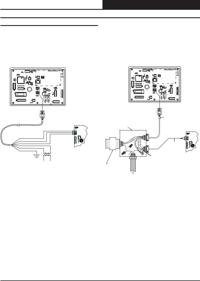
Modular Service Tool
Wether you have a Stand Alone, Interconnected or Networked System, the Modular Service Tool always connects to an HVAC unit controller via a prefabricated cable that is supplied with the service tool. The Modular Service Tool cable is terminated on both ends with a mini DIN connector. Attach one end to the Modular Service Tool and the other end to the mini DIN connector on the HVAC unit controller. If this is an Interconnected System, all controllers that are interconnected with commu-
nications cable can be programmed from any HVAC unit controller on the loop. If this is a Networked System, all controllers on the entire Networked System can be programmed from one HVAC unit controller.
Be sure that the Modular Service Tool has fresh batteries installed or that it is connected to a power source using the supplied power pack before attempting any programming of the controller. See Figure 3 for connection details.
Optional Connection For
Controllers Without DIN Connector
PL101904 Adapter Board
Terminal Block Base
(Remove Terminal Block)
COMM
T
SHLD
R
Female DIN Connector
Male DIN Connector
Typical Controller Board
The Modular Service Tool Can Be Connected To Most
Connector Cable Controllers By Plugging One End Of The Supplied
Cable Into the Modular Service Tool DIN Connector
And The Other End Into The DIN Connector On The
Controllers.
Some Controllers Without DIN Connectors Require
Use Of The Supplied PL101904 Adapter Board Shown
Above. To Connect With Adapter Board, First Unplug
COMM Terminal Block From Controller Board. Plug
PL101904 Adapter Board Terminal End Into Terminal
Block Base On Controller. Plug DIN Connector Cable
Into DIN Connector On PL101904 Adapter Board . See
Optional Connection For Controllers Without DIN
Connector Above For Illustration Of This Connection.
|
|
|
|
|
Modular Service Tool |
|
|
|
|
|
|
|
|
Mode |
|
UP |
|
|
|
Be Sure The Modular Service |
Selection |
|
|
|
|
|
Tool Is Connected To The |
STATUS |
PREV |
|
|
NEXT |
Supplied Power Pack Or Has |
|
|
|
Fresh Batteries Installed Before |
||||
|
|
|
|
|
|
|
SETPOINTS |
|
|
|
|
|
Attempting Programming Of The |
|
ESC |
DOWN |
CLEAR |
|
|
Controller. Be Sure The Power Is |
SCHEDULES |
|
|
|
|
|
Turned Off On The Modular |
|
|
ENTER |
|
|
|
Service Tool Before Connecting |
|
|
|
|
|
|
|
OVERRIDES |
|
|
|
|
|
The Cable To The Controller. |
|
|
|
|
|
|
|
ALARMS |
1 |
2 |
3 |
|
|
|
|
|
|
||||
CONFIGURATION |
4 |
5 |
6 |
|
|
|
BALANCE - TEST |
7 |
8 |
9 |
|
|
|
ON |
DEC |
0 |
- |
|
|
|
|
|
MINUS |
|
|
|
|
Power On Button
Figure 3: Modular Service Tool
4 |
Operator Interfaces |
Modular System Manager
Power and communications are supplied to the System Manager via a modular/pigtail cable that is supplied with the System Manager. This cable has a male Molex connector on one end for connection to the female Molex connector on the System Manager. On the other end are 5 insulated wires with a drain wire which are used for connection to the
YS101830PREV.
2PMODULARPSYSTEM MANAGER
C2 C1 |
X1 |
PHILIPS |
|
P1 |
COMM |
R11 |
|
D4 |
|
|
|
|
|
R10 |
|
|
OUT |
R12 |
|
L1 |
|
|
|
|
U9 |
|
|
P2 |
COMM |
|
|
C4 |
|
|
|
R13 |
||
EPROM |
|
IN |
|
|
CX9 |
|
VAR1 |
470uF50v |
1000uF10v |
RAM |
|
470uF50v |
1000uF10v |
 Modular System Manager
Back of Front Cover
Use Supplied Modular |
|
|
Cable With Stripped Ends |
T |
|
For Connection To Terminal |
||
SHLD |
||
Block And Transformer |
||
R |
||
|
||
WHITE (T) |
|
|
DRAIN WIRE (SHLD) |
|
|
BLACK (R) |
|
|
RED (24 VAC) |
|
|
BROWN (GND) |
|
|
GREEN (GND) |
WMVAV Controller Board |
|
|
Connection Shown |
May Also Be Connected To Any
VAVBOX Controller On Loop
Class 2 Transformer
Rated For 6 VA Minimum
Technical Guide
communication and power wiring from the transformer and from the local loop communications terminal on the WMVAV controller or any VAVBOX controller’s communication terminal. A class II, 24 VAC transformer (by others) rated at 6 VA or greater load capacity is required for powering the System Manager.
See Figure 4 & 5 for System Manager connection and wiring details.
PHILIPS
RAM EPROM
Modular System Manager
Back of Front Cover
HZ000121
Modular Pigtail Cable
Handy Box , Conduit, Supplied With System Manager
Fittings, Wire Nuts,
Butt Splices Etc.,
( By Others)
|
(24 |
VAC) |
|
|
|
T |
|
RED |
|
|
|
|
|
SHLD |
|
|
|
|
|
|
|
||
|
|
|
(GND) |
WHITE |
|
|
R |
BROWN |
KCLAB |
|
|
||||
|
2-Conductor Shielded |
||||||
|
GREEN |
(T) |
)(R |
|
18-Guage |
||
|
|
|
G |
|
|
Communications Wire |
|
|
|
|
( |
|
|
|
|
|
|
|
ND) |
|
|
|
|
LINE |
|
|
|
|
|
|
Controller Board |
VOLTAGE |
|
|
|
|
|
Drain Wire (Shld) |
|
|
|
|
|
|
|
|
|
Class 2 Transformer
Rated For 6 VA Minimum
(By Others)
LINE VOLTAGE
Figure 4 Schematic for Wiring System Manager |
|
Figure 5: Detailed Typical System Manager Wiring |
Using Modular Cable Pigtail |
|
Using Modular Cable Pigtail |
Operator Interfaces |
5 |

Technical Guide
General Programming Information
Operator Interfaces Comparison
In order to configure and program the WattMaster VAV System controllers you must have a central operators interface or a personal computer with the Prism computer front end software installed. Two different central operators interfaces are available for programming of the WattMaster VAV Controls System. You may use either the Modular Service Tool and/or the Modular System Manager to access the status and setpoints of any controller on your communications loop.
The Modular Service Tool or the System Manager allow the user to view any temperature or output condition and change any setpoint to fine tune the operations of the total system. All keypad operations are simple and straightforward, utilizing non-cryptic plain English messages.
Display Screens & Data Entry Keys
The System Manager display screens and the Modular Service Tool display screens are very similar. For most setpoints and modes the only difference between using the Service Tool and the System Manager is a few differences in the function of the keypads. In this manual where a difference in the keypad input or the screens displayed exists between the two operators interfaces, both screens or keypads will be shown. See the chart below for a list of the keypad descriptions and functions.
|
|
|
|
|
|
|
|
|
|
|
|
|
Mode |
|
UP |
|
|
|
|
|
|
|
|
Selection |
|
|
|
|
|
|
STATUS |
PREV |
|
|
NEXT |
|
SETPOINTS |
|
|
|
|
|
|
ESC |
DOWN |
CLEAR |
|
SCHEDULES |
|
|
|
|
|
|
|
|
ENTER |
|
|
|
OVERRIDES |
|
|
|
|
|
ALARMS |
1 |
2 |
3 |
|
CONFIGURATION |
4 |
5 |
6 |
||
BALANCE - TEST |
7 |
8 |
9 |
||
|
ON |
DEC |
0 |
- |
|
|
|
|
MINUS |
||
Modular Service Tool
|
|
|
|
System Manager |
|
|
|
|
|
UP |
STATUS |
|
|
|
|
|
|
1 |
2 |
3 |
|
|
SETPOINTS |
|
|
|
|
|
|
4 |
5 |
6 |
PREV |
|
NEXT |
|
|
SCHEDULES |
|||
7 |
8 |
9 |
|
ESC DOWN CLEAR |
OVERRIDES |
DEC |
0 |
- |
|
|
|
|
MINUS |
|
ENTER |
ALARMS |
|
Modular System Manager
|
Keypad |
|
Key Function |
|
|
Description |
|
|
|
|
|
|||
|
|
System Manager |
Modular Service Tool |
|
|
|
|
||
|
|
|
|
|
|
ESC |
|
Used to exit from screens |
Same function as |
|
|
|
or from data entry. Use |
System Manager |
|
|
|
this screen to return to the |
|
|
|
|
main menu from any |
|
|
|
|
screen in the system |
|
|
|
|
|
|
|
ENTER |
|
This key is used to close a |
Same function as |
|
|
|
data entry field and |
System Manager |
|
|
|
advance to the next item |
|
|
|
|
or screen |
|
|
|
|
|
|
|
Clear |
|
If a data entry mistake is |
Same function as |
|
|
|
made, press this key to |
System Manager but |
|
|
|
clear the data entry field |
also turns off the |
|
|
|
and start over |
power to the Service |
|
|
|
|
Tool when on the |
|
|
|
|
main menu screen |
|
|
|
|
|
|
Minus |
|
If a setpoint with a |
Same function as |
|
|
|
negative value is required, |
System Manager |
|
|
|
press this key for the |
|
|
|
|
minus sign |
|
|
|
|
|
|
|
DEC |
|
Press this key when |
Same function as |
|
|
|
entering data that requires |
System Manager |
|
|
|
a decimal point |
|
|
|
|
|
|
|
|
|
Steps the user to the next |
Same function as |
|
|
|
controller on the loop on |
System Manager |
|
|
|
interconnected or |
|
|
|
|
networked systems |
|
|
|
|
|
|
|
|
|
Steps the user backward or |
Same function as |
|
|
|
forward through the |
System Manager |
|
|
screens |
|
|
|
|
|
|
|
Mode Selection Buttons
Both the System Manager and the Modular Service Tool are provided with “Mode Selection Buttons” . These buttons give the user instant access to the specific mode desired without having to scroll through several menu screens to get there. The Modular Service Tool has 2 extra function keys (“Configuration” and “Balance-Test”) that are not available on the System Manager.
6 |
Operator Interfaces |
Technical Guide
Button |
|
Mode Selection Buttons |
|
Description |
|
|
|
|
|
||
|
Modular Service Tool |
System Manager |
|
|
|
||
|
|
|
|
STATUS |
Pressing this button |
Pressing this button |
|
|
|
takes you directly to |
takes you directly to |
|
|
the controller |
the controller |
|
|
“Status” screens |
“Status” screens |
|
|
|
|
SETPOINTS |
Pressing this button |
Pressing this button |
|
|
|
takes you directly to |
takes you directly to |
|
|
the controller |
the controller |
|
|
“Setpoints” screens |
“Setpoints” and |
|
|
|
“Configuration” |
|
|
|
Menu |
|
|
|
|
SCHEDULES |
Pressing this button |
Pressing this button |
|
|
|
takes you directly to |
takes you directly to |
|
|
the controller |
the controller |
|
|
“Schedules” screens |
“Schedules” screens |
|
|
|
|
OVERRIDES |
Pressing this button |
Pressing this button |
|
|
|
takes you directly to |
takes you directly to |
|
|
the controller |
the controller |
|
|
“Overrides” screen. |
“Overrides” screen. |
|
|
See the “Override |
See the “Override |
|
|
Button” section of |
Button” section of |
|
|
this manual for a |
this manualfor a |
|
|
description of this |
description of this |
|
|
function. |
function. |
|
See Note 1 below. |
See Notes 1 & 2 |
|
|
below. |
|
|
|
ALARMS |
Pressing this button |
Pressing this button |
|
takes you directly to |
takes you directly to |
|
the controller |
the controller |
|
“Alarms” screen. |
“Alarms” screen. |
|
See the “Alarms |
See the “Alarms |
|
Button” section of |
Button” section of |
|
this manual for a |
this manual for a |
|
description of this |
description of this |
|
function. |
function. |
|
See Note 1 below. |
See Notes 1 & 2 |
|
|
below. |
|
|
|
CONFIGURATION |
Pressing this button |
|
|
takes you directly to |
Not Available |
|
the controller |
Use “Setpoints” |
|
“Configuration” |
Button To Access |
|
screens |
Menu |
|
|
|
BALANCE-TEST |
Pressing this button |
|
|
takes you directly to |
|
|
the controller |
Not Available |
|
“Balance-Test” |
|
|
screens |
|
Notes:
1.) This button only functions when the system is configured for “Network Mode” or “Multiple MGRS Mode”. It will not function in ‘Stand Alone Mode”.
2.) The “Search For Units” function must be performed on the System Manager upon initial system setup before this function will be available. See the “System Manager NM & MM Loop Search” section of this manual for complete instructions on performing a loop search.
Service Tool And System Manager
Entering Unit ID (Address)
With both the Modular Service Tool and the Modular System Manager You must enter the ID (Address) of the controller you wish to program
Unit Selection
Enter Unit ID#
Selected ID#: xxxx
With the main menu screen displayed, press the function key associated with the operation (setpoints, configuration, etc.) you want to perform. The screen shown above will appear asking you to enter a unit I.D.# (controller address). Put in the ID# of the controller you wish to communicate with then press the “ENTER” key.
If this is Multiple Loop Network System the Unit ID is actually two separate numbers, combined into one value. The first part of the number contains the Loop Address at which the controller is located. The second part of the number contains the actual controller address. See Examples #1 & #2 below.
EXAMPLE #1
You would like to view the 3rd controller on the 5th loop. Enter “503” as the Unit ID.
EXAMPLE #2
You would like to view the 12th controller on the 24th loop. Enter “2412” as the Unit ID
EXAMPLE #3
You would like to view the only controller on the loop. Enter 1 as the Unit ID. No loop number is required since there is only one loop.
Hit the “Enter” key after entering the unit ID. If you are using the Modular Service Tool you will be taken directly to the first screen for the operation you are trying to program.
Modular System Manager
System Manager Initialization Screens
When the System Manager is powered up, the first screen displays the current version of the software installed in your System Manager and whether your system is configured for Network or Stand-Alone operation. On a Networked System, all controllers on the communications loop are available for programming by entering their loop address (ID).
If the System Manager is configured for Stand-Alone operation, only the HVAC unit controller that the System Manger is connected to is available for programming. The Stand-Alone feature is only used for servicing and testing. For normal operation the System Manager must be configured for Network mode.
Operator Interfaces |
7 |

Technical Guide
General Programming Information
Initializing
System Manager vX.XX
Wattmaster Controls
Network Mode
1)Set Time & Date
2)Communications ->) Next Menu
ESC) Exit Menu
System Manager vX.XX
Monday Operations
09/09/99 04:26 PM
NM Outdoor Air 87°F
The screen above will appear a few seconds later. The last line of the display will have the letters SA (Stand Alone Mode), MM (Multiple System Manager Mode) or NM (Network Mode) followed by the current outdoor air temperature. The System Manager normally ships from the factory set for NM (Network Mode). If you have only one System Manager, the system must be set for NM (Network Mode). If you have multiple System Managers on your system, the system must be set for MM (Multiple System Managers Mode). If you believe your system is incorrectly configured, please follow the instructions that follow. If your system is configured correctly, proceed to the System Manager Network Mode Loop
Configuring For Stand-Alone Mode, Multiple System Managers Mode or Network Mode
As previously described the System Manager must be configured for the correct mode of operation for your system. Again, there are 3 modes of operation available for the WattMaster VAV System. They are “Stand Alone Mode”, “Multiple MGRS Mode” or “Network Mode”.
Look at the bottom line of the display as mentioned in the previous paragraph and determine which one your System Manager is currently set for. If you have a single System Manager for your entire system, then you need to operate in “Network Mode” and the first two characters on the bottom line of the display should be “NM”. If you have multiple System Managers on your system then you need to operate in “Multiple MGRS Mode” and the first two characters on the bottom line of the display should be “MM”. The System Manager should never be set to “Stand-Alone” mode unless you have been instructed to configure this setting by WattMaster Technical Support.
If your display indicates a different mode than the one you need, press the “Enter” key and the following screen will appear.
Press the “2” key on the keypad to enter the communications screen.
THIS ACTION REQUIRES
A SPECIAL HIGH LEVEL
PASSCODE CLEARANCE
Enter: xxxxxxx
Enter the seven digit passcode “2337377” to access the next screen. These seven digits spell the word “ADDRESS” on your telephone keypad if you forget what they are.
You will then see the screen below displayed. You must use the keypad to enter the correct number for the mode of operation needed for your system.
0) Stand Alone
1-60) Multiple MGRS
63) Network System
Enter Mode Of Op:.xx
For “Multiple MGRS Mode” enter the address at which you want this particular System Manager to be set. When multiple System Managers are used on a local loop, each must be set with a unique address different from any other device on that loop. You must perform this same operation again for each System Manager installed. If you want one of these System Managers to be able to indicate alarms and overrides for the entire system you must enter “63” for “Network Mode” on that particular System Manager.
For “Network Mode” (or as explained above for Multiple System Managers when one is to be set to indicate alarms and overrides) enter “63”.
For “Stand Alone Mode” enter “0”.
Once you have the correct number per the display above displayed, press the ENTER key. The following screen will appear telling you that you have changed the system mode. Press any key on the keyboard to exit this screen.
You Have Changed The
System Manager Mode
Press Any Key To
Continue
8 |
Operator Interfaces |

Technical Guide
System Manager NM & MM Mode Loop Search
When the System Manager is configured for Network Mode a loop search must initially be performed for the System Manager to recognize alarms or overrides. Also, when you have a system that has multiple System Managers and you have one of the System Managers set to (63) Network Mode for alarm and override indication, you must also perform a loop search for that System Manager. This allows the System Manager to be aware of all alarms and overrides for all local loops on the entire system. .
Note: The Loop Search function is only required when using the System Manager(s), not the Modular Service Tool.
To access the Loop Search screen, do the following. From the main menu screen press enter to display the following screen.
1)Set Time & Date
2)Communications ->) Next Menu
ESC) Exit Menu
Press the “Next” arrow key. The following screen will be displayed.
1)Change Passcodes
2)Loop Search
<-) Prev. Menu
ESC)Exit Menu
Press the “2” .The following screen will be displayed.
Loop Search
Current Loop = XX
Loops Found = XX
Searching
The System Manager will now proceed to search all loops to find the MiniLink Polling Devices that are connected to the system. The screen will display the current loop being searched and the number of loops currently found.
Once the search is completed the following screen will be displayed.
Loop Search
Finished
Loops Found = XX
Press ESC to Exit
The screen will display the number of loops found on your system. The information will be saved into the System Manager’s memory. No further loop searches will be required unless an additional MiniLink Polling Device is added to the Network System.
System Manager Alarm Search
The System Manager can be used to search for all active alarms on the system. The MiniLink PD must be configured to allow for “Alarm Polling” for each controller that alarming is desired on for this function to work. See the MiniLink PD programming section of this manual for setting information. Press the “Alarm” key. The Unit Selection screen below will be displayed. Enter the Unit ID of any unit on the system and press “Enter”. This is the unit ID of where the alarm search begins. The entire system is searched from this point.
Unit Selection
Enter Unit ID#
Selected ID#: xxxx
The following screen will appear. The System Manager will search for any active alarms on the entire system.
Alarm Screen
SEARCHING!
After the System Manager completes it’s search, it will list the first unit on the system that currently has an active alarm. Press “Enter” to scroll through all the alarms on that particular unit. To move to the next unit or back to the previous unit use the “Prev” or “Next” arrows to move between units with alarms.
Alarm Search Screen
Loop = 1 Unit = 59
Space Sensor Failure
To clear any alarms that are found you must fix the problem indicated in the alarm. Once the problem is fixed, the alarm will clear from the screen the next time the unit is polled.
Operator Interfaces |
9 |

Technical Guide
General Programming Information
System Manager Override Search
When a space sensor with override option is used with any VAVBOX controller or WMVAV controller, the System Manager can determine and report any controllers which are currently operating in an override condition. The MiniLink PD must be configured to allow for “Alarm Polling” for each controller that alarming is desired on for this function to work. See the MiniLink PD programming section of this manual for setting information
To access the Space Sensor Overrides screen, press the “Override” button located on the System Manager . A screen will appear asking you to enter a unit ID. Enter an ID for any active controller on the system and press "Enter". The following screen will appear.
If you wish to change either Level 1 or Level 2 passcodes please see the instructions that follow.
From the main status screen press "Enter", The following screen will appear.
1)Set Time & Date
2)Communications ->) Next Menu
ESC) Exit Menu
Press the “Next” arrow key. The following screen will be displayed.
Overrides Screen |
1) |
Change Passcodes |
SEARCHING! |
2) |
Loop Search |
<-) Prev. Menu |
||
|
ESC)Exit Menu |
|
After the System Manager completes its search, it will list the first unit on the system that is currently in the override mode. Press the previous or next button to scroll through all units that are in the Override Mode.
Overrides Screen
Loop = 1 Unit = 59
Override Unit
Anytime you enter a unit ID with the Modular System Manager you will be asked for a passcode. Passcodes are not required to view Status Screens. The screen below will appear if this action requires passcode clearance.
System Manager Passcodes
Anytime you enter a unit ID with the Modular System Manager you will be asked for a passcode. Passcodes are not required to view Status Screens. The screen below will appear if this action requires passcode clearance.
THIS ACTION REQUIRES
PASSCODE CLEARANCE
Enter Passcode: xxxx
The System Manager has two levels of user access. Level 1 users are limited to viewing or changing the Time, Date, Operating Schedules and Heating and Cooling Setpoints. Level 2 users have complete system access. Any status or setpoint field can be read or reset from the System Manager.
These two levels of passcodes are programmable by any Level 2 user. The default Level 1 passcode is “1111” and the default Level 2 passcode is “2222.”
Press the “1” .The following screen will be displayed.
Enter New Passcode Level 1.....: xxxx Level 2.....: xxxx [Must Be 4 Digits]
This screen allows you to enter new Level 1 or Level 2 passcodes. The actual digits in your passcodes are never displayed. An “X” is used as a place holder for each digit entered. Passcodes must always be four digits in length, so the usable range of numbers is 1000 to 9999.
Caution: If you change the Level 2 passcode and cannot remember what it is, you will be locked out of your system!
Modular Service Tool
The Modular Service Tool is very similar to the System Manager in its operations as stated previously. Two exceptions to this are that the Service Tool unlike the System Manager does not check the entire system when performing an “Alarm” or “Override” search and it does not have any passcoding capability.
Note: When the Alarms or Overrides buttons are pressed on the Modular Service Tool it will search only the loop number of the unit ID that has been entered, therefore each local loop must be searched individually to access all alarms or overrides on the system.
10 |
Operator Interfaces |
Technical Guide
Modular Service Tool Initialization Screen |
Modular Service Tool Alarm Search |
After connecting the Service Tool to the controller with the supplied cable, press the “On” key. The following screen will appear.
Service Tool vX.XX
Monday Operations
09/09/02 04:26 PM
Stand Alone Mode
Configuring The Modular Service Tool For
Network Or Stand-Alone Operation
As with the System Manager described previously, you must determine if the mode displayed is correct for your system. Normally for most applications the words “Network Mode” should be displayed in the window. If it has been configured for Stand Alone mode you will see the words “Stand Alone Mode” on the bottom line of the display. Stand Alone Mode is only used when servicing or troubleshooting and is normally not used for general setup and programming as it only allows the user to access the controller it is attached to and not the entire networked system
If your display indicates a different mode than the one you need, press the "Enter" key and the following screen will appear.
1)Set Time & Date
2)Communications
3)Energy Saving ESC) Exit Menu
Press the “2” key on the keypad to enter the communications screen.
First, press the “Alarm” key. The Unit Selection screen below will be displayed. Enter the Unit ID of any controller on the system and press “Enter”. This is the unit ID of the loop where the alarm search will be done. Unlike the System Manager, only the alarms on this loop will be searched, not the entire system.
Unit Selection
Enter Unit ID#
Selected ID#: xxxx
The following screen will appear. The System Manager will search for any active alarms on the local loop.
Alarm Screen
SEARCHING!
After the Modular Service Tool completes it’s search, it will list the first unit on the local loop, whose ID was entered, that currently has an active alarm. Press “Enter” to scroll through all the alarms for controllers on that particular loop. To move to the next controller or back to the previous unit use the “Prev” or “Next” arrows to move between controllers with alarms on the loop.
Alarm Search Screen
Loop = 1 Unit = 59
Space Sensor Failure
0)Stand Alone
1)Network System
Enter Mode Of Op:.xx
To clear any alarms that are found you must fix the problem indicated in the alarm. Once the problem is fixed, the alarm will clear from the screen the next time the unit is polled.
Modular Service Tool Override Search
As the screen indicates, press the right or left arrow keys to select the proper mode of operation. When you are finished press “Enter” to move back to the main menu screen.
You Have Changed The
System Mode
Press Any Key To
Continue
When a space sensor with override option is used with any VAVBOX controller or WMVAV controller, the Modular Service Tool can determine and report any controllers which are currently operating in an override condition on the local loop whose ID (Address) has been entered before running the search.
To access the Space Sensor Overrides screen, press the “Override” button located on the Modular Service Tool . A screen will appear asking you to enter a unit ID. Enter an ID for any active controller on the particular local loop you wish to search and press "Enter". Unlike the System Manager, only the overrides on this loop will be searched, not the entire system. The following screen will appear.
Operator Interfaces |
11 |
 Loading...