

Page 1

20. WCC II TO WCC III
GLOBAL BRIDGE MANUAL
WCC III
20. WCC II TO WCC III
GLOBAL BRIDGE MANUAL
Page 2

T ABLE OF CONTENTS
SECTION 20: WCC II to WCC III
GLOBAL BRIDGE MANUAL
Overview ...................................................20-1
WccUtility.EXE Program Setup
Considerations and Limitations for
Global Bridge ............................................20-2
SET GLOBAL MAP VIEW ...........................20-3
SET BRIDGE MAP ......................................20-4
Troubleshooting the WCC III RS-485
Communications Loop ..............................20-5
Troubleshooting the WCC II Manchester
Communications Loop ..............................20-6
WCC II Manchester Communication
Boards .......................................................20-8
Page 3
20. GLOBAL BRIDGE BOARD INSTALLATION
SECTION 20:
WCC II to WCC III GL OBAL BRIDGE
MANUAL (SS5012)
__________________________________________
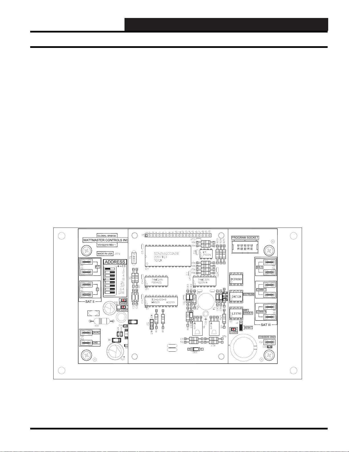
Overview
The “WCC II to WCC III Global Bridge” board provides a means
for the new WCC III system to pass information to and from the
old WCC II system. A single “WCC II to WCC III Global Bridge”
board can simulate (mirror) up to 8 WCC II SAT II Controllers. A
“WCC II to WCC III Global Bridge” can also share Global Binary
and Global Analog information from WCC II to WCC III and
current values of the simulated (mirrored) satellites from WCC III
to WCC II. But this is a one way data fl ow for the Global data, the
direction is from the WCC II system to the WCC III system.
Overview
Figure 20-1: Global Bridge Board
WCC III Technical Guide
20-1
Page 4

20. GLOBAL BRIDGE BOARD INSTALLATION
Setup Global Bridge
WccUtility .EXE Program Setup
Considerations and Limitations for
Global Bridge
To setup the Global Map for the “WCC II to WCC III Global Bridge”,
you only have to fi ll out the data in one “SetGlobalMapView”
window even if you have multiple “WCC II to WCC III Global
Bridges”. This is because all of the “WCC II to WCC III Global
Bridges” will have the same global analog/binary value that will
come from the WCC II front-end computer .
There are no limitations to the number of global analogs or global
binaries that you can setup from within the “SetGlobalMapView”
window. Of course, you cannot setup more than the WCC II limitations of 128 global analogs and 256 global binaries.
The BACKTASK.EXE program that is running on the WCC III
- MCD requires that the WccUtility.exe program be connected
(via an IP connection) to the WCC III - MCD, that the WccUtility.
exe program be opened and running at all times, and that the
“SetGlobalMapView” window also be opened at all times. This IP
connection must be made so that BACKT ASK.EXE can fetch and
retrieve the global values from the “old” WCC II system.
If you close the “SetGlobalMapView” window or the WccUtility.
exe program, the BACKTASK.EXE program will not be able to
retrieve any global values from the “old” WCC II system. This
means that the “SetGlobalMapView” window that does the global
analog and global binaries value transfers will not transfer these
global analog and global binaries values from the “WCC II to
WCC III Global Bridge” board to BACKTASK.EXE program of
WCC III - MCD.
20-2
WCC III Technical Guide
Page 5

20. GLOBAL BRIDGE BOARD INSTALLATION
Setup Global Map View Screen
SET GLOBAL MAP VIEW
Figure 20-2: Set Global Map View Window
From the WCCUtility.EXE program there are two choices for the
“WCC II to WCC III Global Bridge” board. The fi rst selection
choice is <Setup Global Map>. This is where global information
can be sent from the WCC II system to the WCC III - MCD.
Get Global Value From Satellite: Enter the address for the
“WCC II to WCC III Global Bridge” board. This value should be
higher than the last satellite number on your system. After entering
the address, press the <Set Satellite Number> button to lock in
the address. NOTE: The “WCCII to WCCIII Global Bridge” will
not show on the Satellite Summary Screen.
Set Update Speed: xxxx Milli-second: 1000 milliseconds is
entered for each “WCC II to WCC III Global Bridge” board on
the system. If you have three “WCC II to WCC III Global Bridge”
boards, then a value of 3000 milliseconds needs to be entered for
each “WCC II to WCC III Global Bridge” board. When desired
value is entered, press the <Set Update Speed> button to lock in
the “Set Update Speed” value.
<Add New Global Analog> Enter the number of the global
analog you wish to send from the WCCII to the WCCIII and press
the button. The global will be added to the Global Analog fi eld at
the bottom of the screen. There is no limitation to the number of
global analogs entered.
<Delete Global Analog> Enter the number of the global analog
you wish to delete from the Global Analog box and press the
button. The global analog will disappear from the list.
<Add New Global Binary> Enter the number of the global binary
you wish to send from the WCCII to the WCCIII and press the
button. The global will be added to the Global Binary fi eld at the
bottom of the screen. There is no limitation to the number of global
binaries entered.
<Delete Global Binary> Enter the number of the global binary
you wish to delete from the Global Binary box and press the button.
The global binary will disappear from the list.
NOTE: T o receive global analog and global binary values on
the WCC III system from the WCC II system, the mode for the
analog global and binary global on the WCC III system must
be set to external. See Section 3 for programming globals.
WCC III Technical Guide
20-3
Page 6

20. GLOBAL BRIDGE BOARD INSTALLATION
Set Bridge Map
SET BRIDGE MAP
Figure 20-3: The Set Bridge Map Window
From the WccUtility.exe program there are two choices for the
“WCC II to WCC III Global Bridge” board. The second selection
choice is <Set Bridge Map>. This is where satellite information
can be sent from the “new” WCC III - MCD to the old WCC II
system.
Bridge Satellite Number: Enter the address for the “WCC II to
WCC III Global Bridge” board. This value should be higher than
the last satellite number on your system.
<Load Map> After you type in the address Bridge Satellite (SAT
III) number, press the <Load Map> button to see your simulated
satellites (SAT II) that you have selected for simulation.
Simulate Satellites: Enter the satellite number(s) of which you
would like to simulate. There is a maximum of eight satellites per
“WCC II to WCC III Global Bridge” board. These are the SAT II
simulated addresses.
<Set Map> After entering (or adding) satellites to the “WCC II
to WCC III Global Bridge” board, you must press the <Set Map>
button to send the map information to the “WCC II to WCC
III Global Bridge” board. After the map information has been
received, the “WCC II to WCC III Global Bridge” board will
capture the current values from the satellites on the WCC III side
and provide them to the old BACKTASK program that is running
on the WCC II system side for use in the simulated SAT II satellite
logical address.
20-4
WCC III Technical Guide
Page 7

20. GLOBAL BRIDGE BOARD INSTALLATION
Troubleshooting Communication Loops
Troubleshooting the WCC III RS-485
Communications Loop
What is the WCC III RS-485 communications loop
voltage measurement on a SAT III controller or on a
WCC II to WCC III Global Bridge board?
There are two conditions for Voltage measurements of the WCC
III RS-485 communications loop.
1st Condition: The WCC III RS-485 communications loop
is plugged into a SAT III controller or on a WCC II to WCC
III Global Bridge board, and you are measuring the voltage
at the SAT III controller or on a WCC II to WCC III Global
Bridge board.
SAT II CONTROLLER
EACHCONTACT
ISRATED FOR
24VACORVDC
@.5AMPMAX
+V
SAT II
ATI
ON OFF
BATTON/ OFF
PULSE INPUT
L
LOCALSET DISABLE
O
A
D
LOCALSET
TEST
GND
ON OFF
L16
V
0-15VDC
OUTPUT
MINLOAD
IS1K OHM
RESISTIVE
VDCONLY
2134
5678
CHANNEL
2134
567
8
L15
L14
OUT
L13
L12
L11
L10
L9
ON OFF
L8
L7
L6
L5
L4
L3
L2
H
L1
ON OFF
COM
128
64
32
16
8
C
4
2
1
NUMBER
BINARY
INPUTS
BINARY
INPUTS
SAT
POWERCO NSUMPTION
WATTMASTER
CONTROLS GROUP
24 VAC ONLY
15VA / 625mA
GND
24VAC
24VAC
24VAC 120VAC
GROUND
POWER ---
WARNING: OBSERVE POLARITY B ETWEEN THE
SAT II AND THE WCC II TO WCC III GLOBAL
BRIDGE BOARD.
THE GROUND CONNECTIONS MUST BE THE
SAME. DAMAGE TO THE SAT II CONTROLLER
OR TO THE WCC II TO WCC III GLOBAL BRIDGE
BINARY BOARD CAN RESULT IN VOIDING THE
WARRANTY
120VAC WIRING IS BY OTHERS
THE VA RATING FOR THE S AT II CONTROLLER IS 15VA.
THE VA RATING FOR THE SAT III CONTROLLER IS 15VA.
THE VA RATING FOR THE WCC II TO WCC II GLOBAL BRIDGE
BOARD IS 7.5 VA.
TO OTHER
SAT II OR TO
THE WCC II
COMPUTER
WIRE NUT
On the RS-485 loop for a SAT III controller or on a WCC
II to WCC III Global Bridge board, the “T” (+) and ”R” (-)
terminals should measure “T”(+) @ 2.7VDC and “R”(-) @
3.0VDC voltages. These are approximate values, but should
be used as base line measurements.
SHLD
COMMT
COMMR
SATIII
CHASSISGND
TO HSS EXPANSION BOARDS.
UP TO TWO BINARY INPUT
BOARDS, AND UP TO TWO
BINARY OUTPUT BOARDS
MAY BE CONNECTED TO A
SAT III CONTROLLER.
TO OTHE R
SAT III O R TO
WCC III - MCD
SAT III CONTROLLER
ON OFF
BATTON/ OFF
PULSEINPUT
OPTION 3
OPTION 2
OPTION 1
LOCALSET DISABLE
LOCALSET
TEST
ON OFF
L16
L15
L14
BINARY
L13
L12
INPUTS
L11
L10
L9
ON OFF
L8
L7
L6
BINARY
L5
L4
INPUTS
L3
L2
L1
ON OFF
128
64
32
16
8
4
2
SATADDRESS
1
GND
GLOBALBRIDGE
WATTMASTE RCONTRO LSINC
YS102210REV1
MADEINUSA
ADDRESS
R/T
WIRE NUT
C
SATII
24VAC
GND
STATUS
SATREC
SAT III
PROGRAMMABLE CONTROLLER
SATXMIT
HSSREC
ANALOGINPUT
JUMPERSELECTION
HSSXMIT
THERM
STATUS1
STATUS 2
STATUS 3
0-10V
0-5V
0-1V
THERM
0-10V
0-5V
0-1V
THERM
0-10V
0-5V
0-1V
CH
THERM
0-10V
1
0-5V
0-1V
2
THERM
0-10V
3
0-5V
0-1V
4
A4TO 20mASENSOR WILLREQUIREA
50OHMLOAD RESISTORWHENSETFOR
A1VOLT INPUT,ORA 250OHMLOAD
5
RESISTORWHENSETFORA 5 VOLTINPUT.
A2WIRE ROOMSENSORWILLREQUIRE
6
A300OHMLOADRESISTORWHENSET
FORA1 VOLTINPUT.
A3WIREROOMSENSORWILLNOT
7
REQUIREALOAD RESISTORWHENSET
FORA1 VOLTINPUT.
WattMasterControls Inc.
8
LOCALSET
24VAC
WARNING: OBSERVE POLARITY
BETWEEN THE SAT III AND THE WCC II
TO WCC III GLOBAL BRIDGE BOARD GROUND CONNECTIONS MUST BE THE
SAME.
24VAC
24VAC 120VAC
GROUND
120VAC WIRING IS BY OTHERS
POWER
SATIISTAT
0TO1V
INPUT
0TO5V
INPUT
0TO10V
INPUT
THERMISTOR
INPUT
CURRENT
INPUT
PROGRAMSOCKET
PCF8583
24C128
LT1785
COMM
EEPROM
485
DRIVER
VBAT
TO OTHER SAT II
CONTROLLERS OR
TO THE WCC II
COMPUTER
WIRE "RT" TO "RT"
"C" TO "C"
TIE THE "SHIELD"
WIRES TOGETHER
WCC II TO WCC III
GLOBAL BRIDGE
TO OTHER SAT III
CONTROLLERS OR TO
WCC III - MCD
WIRE "T" TO "T"
"R" TO "R"
"SHD" TO "SHD"
Figure 20-4: Wiring diagram showing how to connect the WCC III to WCC II systems using the W CC II to WCC III
Global Bridge board.
WCC III Technical Guide
20-5
Page 8

20. GLOBAL BRIDGE BOARD INSTALLATION
Troubleshooting Communication Loops
2nd Condition: The WCC III RS-485 communications
loop is not plugged into a SAT III controller or on a WCC II
to WCC III Global Bridge board, and you are measuring the
voltage.
On the RS-485 loop for a SAT III controller or, on a WCC
II to WCC III Global Bridge board the “T” (+) and ”R” (-)
terminals should measure “T”(+) @ 3.25VDC and “R”(-) @
3.25VDC voltages. These are approximate values, but should
be used as base line measurement. More than half a volt either
way should be considered a suspected problem.
The RS-485 driver chip is a fi eld-replaceable part. It is W attMaster
Controls part #ID001785. It is the same RS-485 driver that
W attMaster Controls uses on all of its product lines.
The WCC II to WCC III Global Bridge board has 1000 Volts
of optical isolation for the RS-485 driver circuit. It should also
be resistant to having an external AC or DC voltage (up to 50
VAC/VDC) from being applied to the “R”, “T”, and “SHLD”
connections. There is no protection provided for 120 VAC or
greater line voltages for the “R”, “T”, and “SHLD” connections.
Troubleshooting the WCC II
Manchester Communications Loop
What is the WCC II Manchester communications loop
voltage measurement on a SAT II, SAT 2c, or SAT 2d?
It is not recommended to use a voltmeter to troubleshoot the WCC
II communications loop.
This is a really diffi cult voltage to measure. It really requires an
“Oscilloscope” to measure it correctly. But if you have a really
good digital hand held meter that can measure “AC Milli-Volts”
(the cost of such a meter is about $300 or more), you can measure
the voltage between the R/T and C connections (polarity doesn’t
matter). A fl uctuating AC voltage between 100mV AC to 200mVAC
should be present. Your meter should also have a frequency
counter on it, and the frequency should fl uctuate between 0 Hz
and 15.6KHz.
Bad or no WCC II Communications. Do the Resistance
Checks:
Step 1:
with the WCC II Communication loop disconnected and with the
power to the WCC II to WCC III Global Bridge off.
Step 2: SAT II / WCC II - Termination Resistors
Check the resistance between R/T and C on the SAT
a. The resistance should be about 120 ohms (+/- 15 ohms). If
it is, then it is probably OK and you should test the rest of the
WCC II communications loop. Each SAT II controller should
measure this resistance when the WCC II Communication
loop is disconnected and with the power to the SAT II
controller turned off.
b. If the reading is less than 100 ohms, the replacement of the
Manchester Communication board is required.
c. If the reading is more than 135 ohms, the replacement of
the Manchester Communication board is required.
a. Is there a Terminating Resistor on the loop? This may or
may not be a problem. Terminating resistors are connected
across the RT / C connections on the SAT, usually at the end of
the physical run of wire.
NOTE: If the WCC II communication loop splits into a “T”,
then there may be TWO or more of these terminating resistors.
The value of the terminating resistors may vary but should
be between 10 and 50 ohms. Also, if you are on a job that
has these terminating resistor(s ) , then you should realize that
this job has had a problem before in the past with this echoing
effect. Great care must be taken so that these terminating
resistor(s ) are put back on or that you note where they were in
case there is still a problem.
When troubleshooting the WCC II communications loop, the
following is the recommended procedure:
20-6
WCC III Technical Guide
Page 9

20. GLOBAL BRIDGE BOARD INSTALLATION
Troubleshooting Communication Loops
Step 3: SAT II controller Manchester boards’ impedance
mismatching problem:
a. When installing a new SAT II controller to your system,
the new SAT II controller appears to not work and/or other
previous working SAT II controllers now stop communicating.
This is a classic Manchester board impedance mismatching
problem. It is a diffi cult problem to fi x. The fi x involves
updating all of your SAT II controllers’ Manchester boards to
the current impedance.
b. Newer SA T II controllers Manchester boards have a
different R T to C resistance impedance than the much older
Manchester boards (more than 15 years old). The “New” R T
to C resistance should read about 120 ohms (+/-15 ohms).
c. Older Manchester boards have RT to C resistance
impedance’s of 18 (+/- 5) ohms or some even have
impedances of over 200 ohms. To guarantee the proper
operation of the WCC II communications loop, all SAT II
controllers Manchester boards should have the same RT to C
resistances. It has been WattMaster’s experience that when
the SAT II controllers’ Manchester boards’ impedances match,
the WCC II communications loop will work. Also, it is
recommended that the whole SAT II controller as a complete
assembly will need to be rebuilt and have all of the latest
upgrades preformed.
Step 4: Have you run the LOOPTEST diagnostics on the WCC
II computer?
a. The Looptest program must be run with 1000 passes
per SAT II controller in order to determine if a WCC II
communication problem exists with a particular SAT II
controller.
b. Make note of any failures of all of your SAT II controllers
on the loop as this will be useful in determining if a WCC II
communications problem exists.
c. If a SAT is failing a lot of passes (20 %), then disconnect
it from the communications loop. It could be causing an
intermittent communications problem with other SAT II
controllers that are on the WCC II communications loop.
d. It would be also helpful if you know how the
communications loop was ran - if it was split into multiple
loops converging into one at some point - because one of these
WCC II communications loops may be cut or disconnected,
and this may be the source of your problem.
NOTE: Before testing the Z-80 board for loop test diagnostics,
the clock chip on the WCC II front-end computer’s Z-80
board must be initialized. This is best done by setting the time
and date from within the WCC II program via the System
Parameters Screen. If the time and date are not initialized, this
could cause 3 or 4 failed passes per 1000 passes.
WCC III Technical Guide
20-7
Page 10

20. GLOBAL BRIDGE BOARD INSTALLATION
SAT II MANCHESTER BOARD
SAT II MANCHESTER BOARD
WITH BLUE POT - DO NOT USE
WCC II Manchester Boards
WCC II Manchester Communica tion
Boards
Figure 20-5: SAT II Manchester Boards
WattMaster Controls, Inc. in the past has produced two types
of Manchester Communication Boards - the early Manchester
Communication Board with an adjustable “Blue Potentiometer”
and the later Manchester Communication board without the “Blue
Potentiometer”. Use of the early Manchester Communication
Board with the “Blue Potentiometer” is not recommended for use
with the WCC II to WCC III Global Bridge board.
20-8
WCC III Technical Guide
Page 11

20. GLOBAL BRIDGE BOARD INSTALLATION
WCC II Manchester Boards
P
Figure 20-6: SAT II Manchester Board Jumpers
Please note the following:
• The later Manchester Communication Board will
need to have the 50 ohm load resistors installed on
it instead of the zero ohm jumper.
• Location R24 and R25 should have a 50 ohm load
resistor installed.
• A zero ohm jumper has a single Black band on it.
A 50 ohm resistor should have the color code of
“GREEN” “BROWN” “BLACK” “GOLD”.
P
WCC III Technical Guide
20-9
Page 12

20. GLOBAL BRIDGE BOARD INSTALLATION
20-10
WCC III Technical Guide
 Loading...