

Page 1

18. SAT 3P (Pulsemeter)
Controller Manual
WCC III
18. SAT 3P (Pulsemeter)
Controller Manual
Page 2

T ABLE OF CONTENTS
SECTION 18: SA T 3P (PULSEMETER)
CONTROLLER MANU AL
Overview ...................................................18-1
SAT 3P Pulse Input and Components ....... 18-2
SAT 3P Addressing .....................................8-4
SAT 3P Basic Wiring .................................18-5
SAT 3P Typical Wiring ..............................18-6
Analog Input Screen ...................................8-7
Energy Consumption Screen ..................18-10
Page 3
18. SAT 3P INSTALLATION GUIDE
Overview
SECTION 18:
SA T 3P (PULSEMETER)
CONTROLLER MANU AL (SS5013)
__________________________________________
Each SAT III controller has a single general purpose AIN 1 input
that is an Analog Input / high speed binary capture input which can
also be used as a pulse meter input. The SAT III controller can only
interface to 1 pulse meter.
The SA T 3P controller is in the simplest terms a stripped down SAT
III controller. The SAT 3P controller has no binary logic inputs, no
relay outputs, no analog inputs, no analog outputs, and no HSS
expansion port. The SAT 3P controller has eight high speed binary
capture inputs used for pulse meter type inputs.
Why would you want to purchase a SAT 3P controller? Cost and
labor are the major factors. To do tenant sub-metering for 16
tenants, you would normally need to buy 16 SAT III controllers.
This would be a fairly high and costly expenditure. The same 16
tenant sub-metering can now be accomplished by using two SAT
3P controllers. Also, wiring is an issue. It is easier to wire 16 pulse
meter outputs to two SAT 3P controllers than it is to wire to 16
SAT III controllers that could be scattered throughout the building.
The SAT 3P controllers should ideally be located next to the pulse
meters. This is so that the binary outputs from the pulse meters
can readily and easily be connected to the inputs of the SAT 3P
controller.
The SAT 3P controller is used to interface up to 8 pulse meters
per SAT 3P controller. The SAT 3P simulates 8 SAT III satellites
on the WCC III communications loop. The one and only input
that is used per simulated satellite is AIN 1. This AIN1 input is no
longer a general purpose analog input on the SAT 3P controller.
This AIN 1 input is a specialized high speed capture binary input,
and is designed to detect pulse type inputs. All other satellite inputs
and outputs are non-functional on these 8 simulated satellites.
The Trendlog capabilities are still functional on these 8 simulated
satellites.
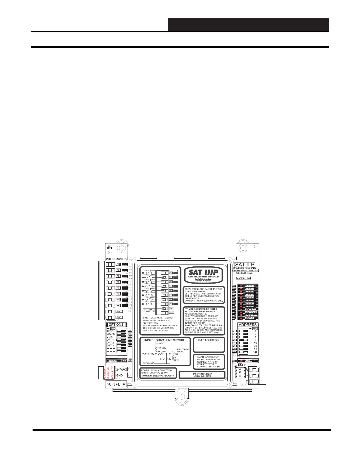
Figure 18-1: SAT 3P Controller
WCC III Technical Guide
18-1
Page 4
18. SAT 3P INSTALLATION GUIDE
SA T 3P Pulse Input and Components
When used in conjunction with the WCC III system, the SAT III
controllers and SAT 3P controllers are capable of recording ener gy
demand, energy consumption, as well as sub-metering, and then
automated logging of tenant power usage. Sophisticated turning
OFF of high usage energy equipment when there is high energy peak
demand time is also possible with what is called “Shed and Restore
Program” via the WCC III system. This can be accomplished by
using a pulse meter on the building incoming power that outputs a
binary contact closure to a pulse meter input on a SAT III or SAT
3P controller. Then, by making global analog and/or global binary
determinations, make an intelligent decision as to what equipment
to keep on and what equipment to turn off.
The binary outputs from the pulse meter(s) must be of the isolated
output type. They can be of the optically coupled open-collector
current sink transistor output type or an actual dry contact type of
output. Please consult with WattMaster Controls if you have any
questions at all about the type of connection from the Pulse Meter
to the SAT 3P controller(s).
The binary input circuit equivalent of the SAT 3P controller is
summarized in Figure 18-2:
The E-Mon D-Mon P2 Pulser output module is an optically coupler
interface device that allows the Class 2000 kWh or KWh/Demand
meter to be connected to an energy/building management system
(EMS) for the purpose of data-gathering and/or load control.
The pulse width and value are selected using the 2 DIP switches
and can be tailored to fi t you specifi c requirements in the fi eld. A
modular plug connects the P2 Pulser output module to the E-Mon
D-Mon meter. A two position screw terminal block provides an
easy connection to the EMS (SAT 3P controller). An LED on the
P2 Pulser output module shows the rate and duration of the pulse
output that is going to the EMS (SA T 3P Controller). The P2 Pulser
output module has an output operation of 4.5 to 28 volts DC that is
to be supplied by the EMS. (SAT 3P Controller)
Please refer to Figure 18-3 for referencing the following
components of the SAT 3P controller:
Communications T erminal Block (Labeled TB2)
The SA T 3P connects to the WCC III system the same way as other
SAT III, and SAT 3C/D,F controllers do via a proprietary RS-485
network. The physical network layer consists of a two -wire twisted
pair with shield wire. WattMaster Controls can provide a detailed
specifi cation for this wire as well as provide 500’ or 1000’ spools
of this wire. All terminated wiring is by three position unpluggable
terminal blocks or single unpluggable ¼ inch spade connections.
When terminating wire, connect “R” to “R”, “T” to “T”, and
“SHLD” TO “SH” throughout the whole WCC III system.
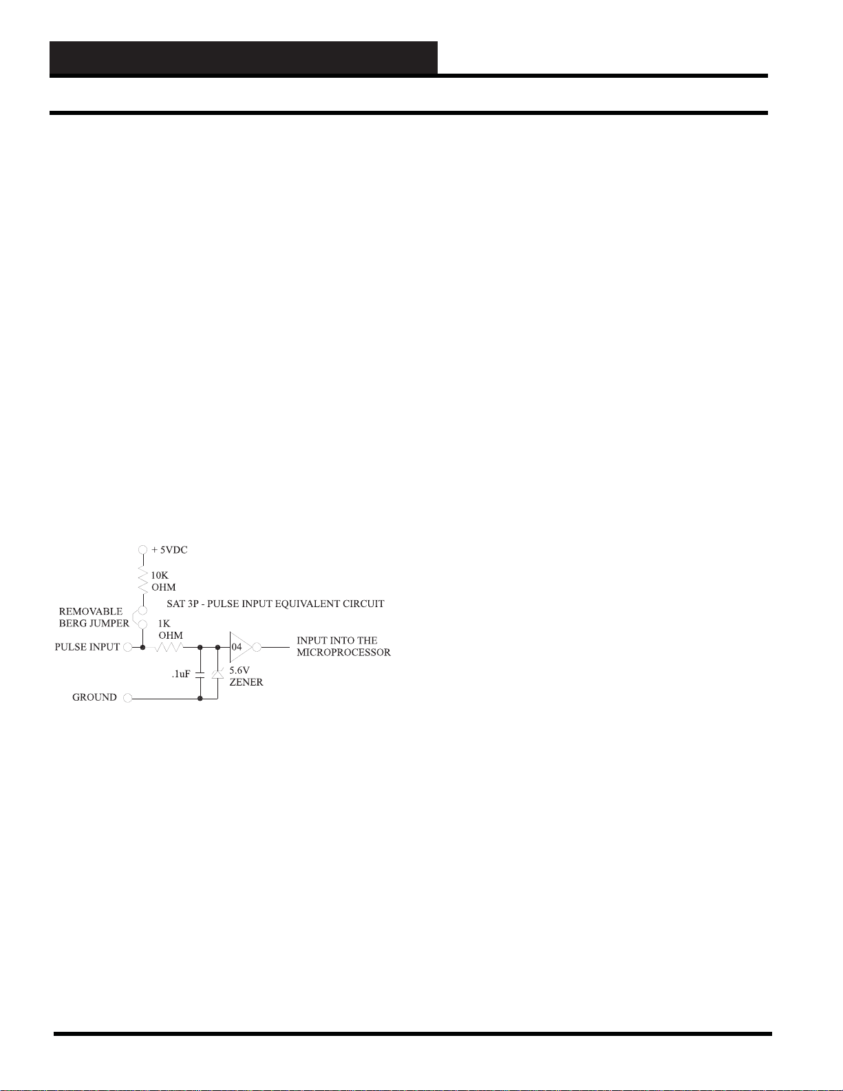
Figure 18-2: Schematic showing the SA T 3P Pulse
Input equivalent circuit multiplied times eight circuits
The two position Removable Berg Jumper on each of the eight
Pulse Inputs on the SAT 3P controller are normally connected.
These Removable Berg Jumpers connect a +5 volt DC pull up via
a 10K ohm current limit resistor to each of the eight Pulse Inputs
on the SAT 3P controller. These Removable Berg Jumpers are to
be removed only if an external voltage source is to be used with the
pulse meter output.
WattMaster Controls-approved pulse meter with isolated outputs
are E-Mon D-Mon Class 2000 Three-Phase kWh or KWh/Demand
meter with the optional E-Mon D-Mon P2 Pulser output module.
Comm LED
This LED is tied to the “DIR” line of the RS-485 driver chip
(LT1785 – WM Part # ID001785). It will slightly blink on receipt
of a communications packet.
Power In Terminal Block (Labeled TB3)
Connect 24VAC and Ground from a transformer. Warning:
Observe Polarity. We recommend using a separate transformer,
but as long as the same polarity is used for 24VAC and GND on
all Satellite connections, then multiple Satellite controllers can be
powered off of a single transformer, as long as you do not exceed
the VA rating of the transformer. Use a self-fusing transformer or
use a suitable sized fuse for your transformer that accounts for the
total VA draw. The Sat 3P draws 3 VA, SAT III draws 15VA, and
the SAT 3C/D/F draws 10VA.
Power LED
This LED is tied to the +5 Volt DC power supply of the SAT 3P
controller. This LED should always be “ON” and never blink.
18-2
WCC III Technical Guide
Page 5
18. SAT 3P INSTALLATION GUIDE
SA T 3P Components
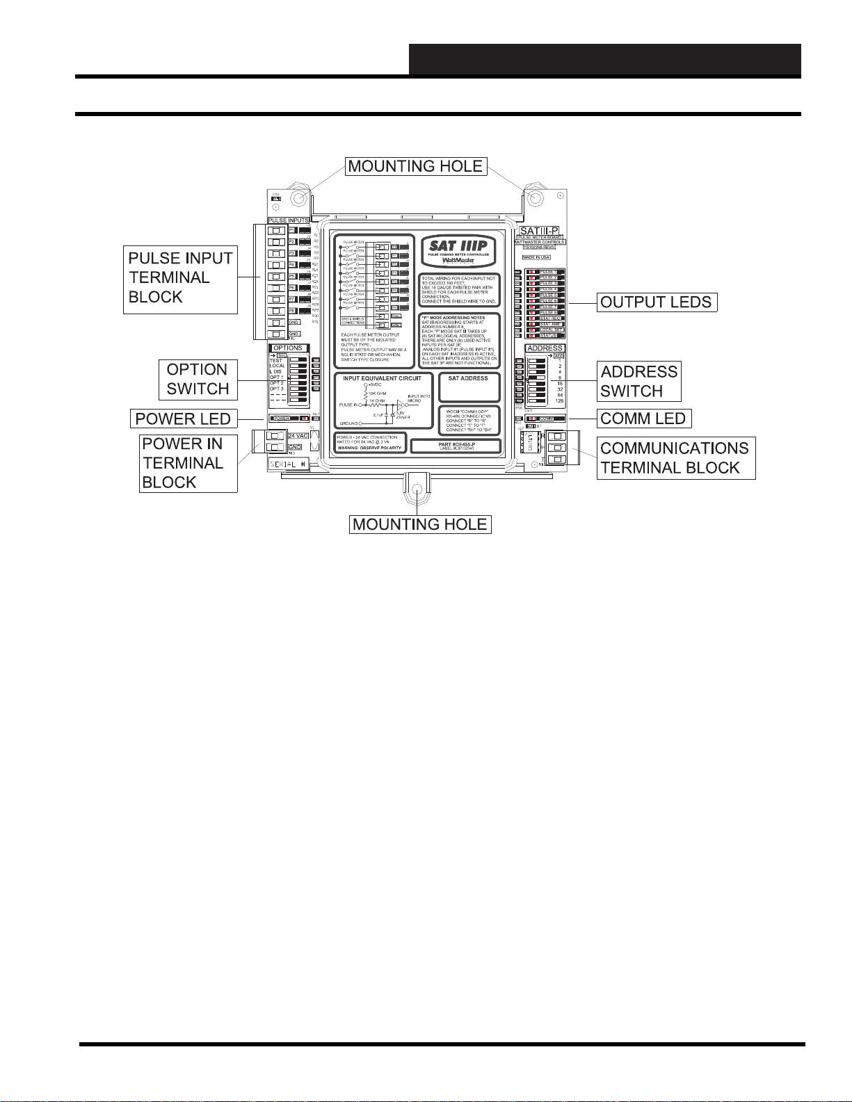
Figure 18-3: SAT 3P P oints of Interest
Pulse Input Terminal Block (LABELED TB1)
This 10-position terminal block is connected to the Pulse meter(s)
output. There are eight input connections and two ground terminals
provided for ground connections. See Figure 18-5.
Output LEDs
PULSE 1 to PULSE 8 LEDs. These LEDs are not physically
connected to the actual high speed binary capture inputs. They are
software controlled outputs from the microprocessor that is on the
SAT 3P controller. This enables true output status to be displayed
of the actual pulse inputs.
STAT LEDs
There are two STAT LEDs—STAT REC and STAT XMIT.
Whenever the microprocessor transmits a communications packet,
the ST A T XMIT LED will be “ON”. Whenever the microprocessor
receives a communications packet, the STAT REC LED will be
“ON”. The ST ATUS LED blinks out a heart beat status of the SA T
3P controller.
LOCAL SET LED
This LED is normally off, but when the SAT 3P is not
communicating to the WCC III – MCD, this LED will be “ON”
solid.
Option Switches
TEST Switch—When this switch is “ON,” then the SAT 3P
will operate to any input condition that has the word “TEST”
programmed into the setpoint.
LOCAL Switch—When this switch is “ON,” then the SAT
3P operates to the LOCAL SET conditions. Also the SAT 3P
controller will operate in the LOCAL SET conditions when it has
lost communications to the rest of the WCC III communications
loop. This Local set condition should be indicated by the LOCAL
SET LED being “ON”.
L DIS Switch—When this switch is “ON,” then the SAT 3P will
not operate to the LOCAL SET conditions. It should control to
setpoints that are based on the “ON” schedule.
OPT 1, OPT 2, OPT 3 switches—These three switches are not
used at this time.
Mounting Holes
Use the three supplied sheet metal screws to mount the SAT 3P
controller in a suitable enclosure. You must use all three screws to
mount the SAT 3P controller.
WCC III Technical Guide
18-3
Page 6

18. SAT 3P INSTALLATION GUIDE
SA T 3P Addressing
Address Switch
An eight position Dip Switch is provided for Satellite addressing.
Each SAT 3 type controller must have its own unique address.
There are 256 possible addresses that can be set with this address
switch. The WCC III system is limited to 239 Satellite addresses
maximum. The SAT 3P addressing starts at address # 8 and ends at
address # 232. Each SAT 3P controller takes up (uses) 8 physical
addresses. Figure 18-4 shows all of the possible addresses for a
SAT 3P controller.
Figure 18-4: Possible Addresses for SAT 3P Controller
18-4
WCC III Technical Guide
Page 7

KW
METER
KW
METER
KW
METER
KW
METER
KW
METER
KW
METER
KW
METER
KW
METER
Typical Wiring Diagram
Use the following Pulse Meter
E-Mon D-Mon Series 2000
with P2 Pulser Output option
Times eight Pulse Meters.
(+)(-)
(+)(-)
(+)(-)
(+)(-)
(+)(-)
(+)(-)
(+)(-)
(+)(-)
SAT 3P
CONTROLLER
PULSE INPUTS
P1
P2
P3
P4
P5
P6
P7
P8
GND
GND
OPTIONS
SEL
TEST
LOCAL
LDIS
OPT1
OPT2
OPT3
POWER
24 VAC
GND
24VAC
FUSED
24VAC 120VAC
GROUND
TOTALWIRING FOR EACH INPUT NOT
TO EXCEED 100 FEET.
USE 18 GAUGETWISTED PAIR WITH
SHIELD FOR EACH PULSE METER
CONNECTION.
CONNECTTHE SHIELD WIRE TO GND.
“P”MODE ADDRESSING NOTES
SATIII ADDRESSING STARTSAT
ADDRESS NUMBER 8.
EACH "P" MODE SATIII TAKES UP
(8) SATIII LOGICAL ADDRESSES.
THEREARE ONLY (8) USED ACTIVE
INPUTS PER SAT3P.
ANALOG INPUT#1 (PULSE INPUT #1)
ON EACH SATIII ADDRESS IS ACTIVE.
ALLOTHER INPUTS AND OUTPUTS ON
THE SAT3P ARE NOT FUNCTIONAL.
18. SAT 3P INSTALLATION GUIDE
SA T 3P Basic Wiring
SATIII-P
PULSE METER BOARD
ATTMASTER CONTROLS
YS102268 REV0
MADE IN USA
PULSE 1
PULSE 2
PULSE 3
PULSE 4
PULSE 5
PULSE 6
PULSE 7
PULSE 8
STATREC
STATXMIT
LOCALSET
STATUS
ADDRESS
ADD
1
2
4
8
16
32
64
128
COMM
R
SH
T
TO OTHER SAT III CONTROLLERS,
SAT 3C/D/F CONTROLLERS,
SAT 3P CONTROLLERS, OR TO THE
WCC III - MCD COMPUTER
WIRE "R" TO "R", "T" TO "T", "SHLD" TO "SHLD"
WARNING: OBSERVE POLARITY
BETWEEN THE SAT 3P CONTROLLER
AND THE REST OF THE SAT 3 TYPE
CONTROLLERS - THE GROUND
CONNECTIONS MUST BE THE SAME.
Figure 18-5: Basic SAT 3P Controller Wiring Diagram
Basic Wiring Instructions
Use 16 or 18 gauge stranded wire to wire from the KW pulse meter
to the SAT 3P controller. Wiring from the transformer to the SAT
3P should also be 16 or 18 gauge stranded wire. Warning: Observe
Polarity on all power wiring. All wiring is to be done in accordance
with all national, state, and local electrical codes.
Basic Communications Wiring Instructions
Use 18 or 20 gauge - 2 conductor twisted pair with shield. This
wire should also be Plenum Rated WattMaster Controls stocks
Plenum Rated - 2 conductor twisted pair with shield wire.
WattMaster Controls part #WR-NL-WG-18 is for a 500 foot
spool and part #WR-LL-WG-18 for the 1000 foot spool. No more
than two conductors are allowed per contact of the three position
communications terminal block. No wire nuts are to be used on the
Communications wiring. WattMaster Controls also has a Power
& Switchable Communications board available for purchase. To
connect one Satellite controller to another Satellite controller you
must wire the “R”, “T”, and “SHLD” or “SH” connections as
follows: Wire all of the dif ferent satellites “R” connections to “R”,
wire all of the different satellites “T” connections to “T”, and wire
all of the different satellites “SHLD” or “SH” connections to “SH”
or “SHLD”.
The transformer used for powering the SAT 3P controller needs to
be of the self fusing type or it needs to have an appropriately sized
fuse on the secondary side of the transformer (24VAC side).
WCC III Technical Guide
18-5
Page 8

18. SAT 3P INSTALLATION GUIDE
SA T 3P Typical Wiring
KW
METER
(+)
SAT III Typical Wiring Diagram
Use the following Pulse Meter
E-Mon D-Mon Series 2000 with the P2 Pulser
Output Module option
Can only connect One Pulse Meter per SAT III.
SAT IIIAin #1 jumper set for 0-5V input,
Vout #1 output voltage programmed for
constant 5 volt output. PULSE INPUT switch
"ON".
(-)
(-)
SAT 3PTypical Wiring Diagram
Use the following Pulse Meter
E-Mon D-Mon Series 2000 with P2 Pulser Output Module option.
KW
Times eight Pulse Meters.
METER
(+)(-)
KW
METER
(+)
KW
METER
(+)(-)
KW
METER
(+)(-)
KW
METER
(+)(-)
KW
METER
(+)(-)
KW
METER
(+)(-)
KW
METER
(+)(-)
SAT III CONTROLLER
0-15VDC
OUTPUT
MIN LOAD
IS 1K OHM
RESISTIVE
VDC ONLY
EACH CONTACT
IS RATED FOR
24VAC ORVDC
@ .5AMP MAX
SAT 3P
CONTROLLER
PULSE INPUTS
P1
P2
P3
P4
P5
P6
P7
P8
GND
GND
OPTIONS
SEL
TEST
LOCAL
LDIS
OPT1
OPT2
OPT3
POWER
24 VAC
GND
WARNING: OBSERVE POLARITY
BETWEEN THE SAT 3P CONTROLLER
AND THE SAT III CONTROLLER GROUND CONNECTIONS MUST BE THE
SAME.
TOTALWIRING FOR EACH INPUT NOT
TO EXCEED 100 FEET.
USE 18 GAUGETWISTED PAIR WITH
SHIELD FOR EACH PULSE METER
CONNECTION.
CONNECTTHE SHIELD WIRE TO GND.
“P”MODE ADDRESSING NOTES
SATIII ADDRESSING STARTSAT
ADDRESS NUMBER 8.
EACH "P" MODE SATIII TAKES UP
(8) SATIII LOGICALADDRESSES.
THEREARE ONLY (8) USEDACTIVE
INPUTS PER SAT3P.
ANALOG INPUT#1 (PULSE INPUT #1)
ON EACH SATIII ADDRESS ISACTIVE.
ALLOTHER INPUTS AND OUTPUTS ON
THE SAT3PARE NOT FUNCTIONAL.
ON OFF
ON OFF
ON OFF
ON OFF
SATIII-P
PULSE METER BOARD
ATTMASTER CONTROLS
YS102268 REV0
MADE IN USA
PULSE 1
PULSE 2
PULSE 3
PULSE 4
PULSE 5
PULSE 6
PULSE 7
PULSE 8
STATREC
STATXMIT
LOCALSET
STATUS
ADDRESS
COMM
R
SH
T
BATTON/ OFF
PULSE INPUT
OPTION 3
OPTION 2
OPTION 1
LOCALSET DISABLE
LOCALSET
TEST
L16
L15
L14
L13
L12
L11
L10
L9
L8
L7
L6
L5
L4
L3
L2
L1
128
64
32
16
8
4
2
1
ADD
1
2
4
8
16
32
64
128
BINARY
INPUTS
BINARY
INPUTS
SATADDRESS
STATUS
SATREC
SATXMIT
HSS REC
HSS XMIT
LOCAL SET
STATUS 1
STATUS 2
STATUS 3
GND
24VAC
24VAC 120VAC
GROUND
120VAC WIRING IS BY OTHERS
THE VA RATING FOR THE SAT III IS 15VA.
THE VA RATING FOR THE SAT 3C IS 10VA.
THE VA RATING FOR THE SAT 3D IS 10VA.
THE VA RATING FOR THE SAT 3P IS 3 VA.
SAT III
PROGRAMMABLE CONTROLLER
ANALOG INPUT
JUMPER SELECTION
THERM
0TO 1V
0 - 10V
0 - 5V
INPUT
0 - 1V
THERM
0TO 5V
0 - 10V
0 - 5V
INPUT
0 - 1V
THERM
0TO 10V
0 - 10V
INPUT
0 - 5V
0 - 1V
CH
THERM
0 - 10V
1
2
3
4
5
6
7
8
WARNING: OBSERVE POLARITY
BETWEEN THE SAT III CONTROLLER
AND THE SAT 3P CONTROLLER GROUND CONNECTIONS MUST BE THE
SAME.
24VAC
FUSED
THERMISTOR
0 - 5V
INPUT
0 - 1V
THERM
0 - 10V
CURRENT
0 - 5V
INPUT
0 - 1V
A4 TO 20 mASENSOR WILL REQUIRE A
50 OHM LOAD RESISTORWHEN SET FOR
A1 VOLTINPUT, OR A250 OHM LOAD
RESISTORWHEN SET FORA 5 VOLT INPUT.
A2 WIRE ROOM SENSOR WILLREQUIRE
A300 OHM LOAD RESISTOR WHEN SET
FORA1 VOLT INPUT.
A3 WIRE ROOM SENSOR WILLNOT
REQUIREALOAD RESISTOR WHEN SET
FORA1 VOLT INPUT.
WattMaster Controls Inc.
TO OTHER SAT III CONTROLLERS, OR
SAT 3C CONTROLLERS, OR SAT 3D
CONTROLLERS, OR SAT 3F CONTROLLERS,
OR SAT 3P CONTROLLERS,
OR TO THE WCC III - MCD COMPUTER
WIRE "R" TO "R", "T" TO "T", "SHLD" TO "SHLD"
TO HSS EXPANSION BOARDS.
UP TO TWO BINARY INPUT
BOARDS, AND UP TO TWO
BINARY OUTPUT BOARDS
MAY BE CONNECTED TO A
SAT III CONTROLLER.
TO OTHER
SAT III OR TO
WCC III - MCD
Figure 18-5: SAT 3P Controller Typical Wiring Diagram
When sharing a common transformer to power other Satellite
Controllers, the transformer used for powering multiple SAT III,
SA T 3C, SAT 3D, SA T 3F , or SAT 3P controllers needs to be of the
self fusing type, or the transformer needs to have an appropriately
sized fuse on the secondary side of the transformer (on the 24VAC
side). VA ratings for the various Satellites that are connected to the
satellite controllers must be accounted for and must be added up,
and an appropriate sized transformer must be used, along with an
appropriate sized fuse on the secondary side of the transformer that
must also be used. All wiring is to be done in accordance with all
national, state, and local electrical codes.
18-6
The transformer used for powering the SAT 3P controller needs to
be of the self fusing type or it needs to have an appropriately sized
fuse on the secondary side of the transformer (24VAC Side).
WCC III Technical Guide
Page 9

18. SAT 3P INSTALLATION GUIDE
Analog Input Screen
Satellite # 1 ANALOG INPUT # 1
Description: Test Pulse Type: Pulse
Pattern for values associated with this input: x,xxx
Units of Measure message #: 2
100 Pulses = 1,000 KW Hours Filter time constant: 64 seconds
ALARMS
Controlled by: 0 Limits Low High
Alarm Type: 0 On 0 0 KW
Alarm Message #’s: Low 0 High 0 Off 0 0 KW
Alternate limits selected by: / / / / On (alt) 0 0 KW
Off (alt) 0 0 KW
Limit overlap time
after control change: 0 Seconds Local set 0 0 KW
BINARY SETPOINT
OFF Above 0.0 KW On Message #: 0
OFF Below 0.0 KW Off Message #: 0
HOME for menu
Figure 18-6: Analog Input Screen
Satellite # _______
Specifi es the number of the satellite which you are currently
editing. If you would like to edit a different satellite, use the arrow
keys to move the cursor to this fi eld, type in the desired satellite
number, and press <Enter>.
Analog Input # ________
This “fi eld” actually contains two separate fi elds. The fi rst fi eld
specifi es the point “type” (i.e., analog input, control output, analog
output, etc.) and displays the current type in textual form. Because
this is a “choice” fi eld, the list of available choices will be displayed
at the bottom of the screen:
Additionally, this fi eld specifi es the point number to edit. For the
Analog Input Screen, this number can range from one to eight,
corresponding from A1 to A8, respectively. If you would like to
edit a different point, move the cursor to this fi eld by using the
arrow keys, enter the desired point number, and press <Enter>.
NOTE: When using the S AT3 P, only Analog Input #1 will
be used per simulated satellite (there are 8 simulated satellites
per SAT3P ). All other satellite inputs and outputs are nonfunctional on these 8 simulated satellites. The trendlo g
capabilities are still functional on these 8 simulated satellites.
<ANALOG INPUT, CONTROL OUTPUT, ANALOG OUTPUT,
TREND LOGGING, LOGIC SWITCH, BINARY OUTPUT>
You may make your selection by pressing the <space bar> until
the desired choice appears and then pressing <Enter>. (If you select
a point type that is different than that currently being displayed, the
screen will be rewritten with the appropriate screen and data.)
WCC III Technical Guide
Description:
A short message is entered here which is displayed on Summary
Screens to help you remember points within the system. You may
enter up to ten characters (control codes, ALT codes, and the double
quote character are not allowed).
18-7
Page 10

18. SAT 3P INSTALLATION GUIDE
Analog Input Screen
Type:
This fi eld is automatically fi lled in by the system. On the SAT 3P,
it will always be “PULSE”.
Pattern for Values Associated With This Input:
Specifi es where you would like the decimal point to appear in the
value displayed by the system. Because this is a “choice” fi eld,
a list of available choices will be displayed at the bottom of the
screen:
< x,xxx , xxx.x , xx.xx , x.xxx >
You may make your selection by pressing the <space bar>
until the desired data pattern has been selected and then pressing
<Enter>.
Units of Measure Message #: ____
A number is entered here that references a message on the On/Off
Units Messages Screen. For example, if units-of-measure message
#4 is “KW” entering “4” will cause “KW” to be displayed as the
units-of-measure for the analog input.
_______ Pulses = _______ Hours
Specifi es the calibration information for the pulse meter. The fi rst
input is a “choice” fi eld, and therefore a list of available choices
will be displayed at the bottom of the screen.
< 100, 1000 >
The second input is used to “scale” or “calibrate” the particular
sensor that is being used. For example, consider a pulse meter
which measures the kwh of a building. Electrical meters are
basically a small motor whose speed is proportional to power
being used. Let’s consider a meter where one revolution equals
one kwh, and the meter sends 5 pulses to the satellite controller for
every 6 revolutions. Therefore, we would enter “100 Pulses = 120
kwh hours.” (NOTE: maximum pulse rate allowed = 4 pulses per
second.)
Filter Time Constant: ____ Seconds
Specifi es the sampling rate of the analog input. This is used by the
satellites to “fi lter” (or smooth) the analog input signal. This can be
used on inputs that “jump around” to reduce sporadic load control.
Because this is a “choice” fi eld, the list of available choices will be
displayed at the bottom of the screen:
< 0, 1, 2, 4, 8, 16, 32, 64 >
You may make your selection by pressing the <space bar> until
the desired fi lter time constant has been selected and then pressing
<Enter>.
------ALARMS------
Controlled by:
Specifi es the binary value that selects the ON or OFF alarm limits.
When this value is OFF , the OFF alarm limits are selected; when it
is ON, the ON alarm limits are selected.
Alarm Type:
Specifi es the priority (or “importance”) level for any alarms
generated by this input. Alarm types range from one (highest
priority) to eight (lowest priority). The system displays and e-mails
higher priority alarms fi rst. (The fi rst fi ve alarm priorities (1-5)
have e-mail-out-on-alarm capabilities.)
Alarm Message # Low: ___ High: ___
Specifi es a pair of message numbers, one for LOW alarms and
the second for any HIGH alarms. These numbers are used by
the system to reference a message which is entered on the Alarm
Message Screen.
5 pulses = 6 revolutions
1 revolution = 1 kwh
5 pulses = 6 kwh
100 pulses = 120 kwh
18-8
WCC III Technical Guide
Page 11

18. SAT 3P INSTALLATION GUIDE
Analog Input Screen
Alternate Limits Selected By:
Specifi es the point that initiates the Alternate mode. When this
address is zero (or OFF), the Normal alarm limits are selected;
when it is one (or ON), the Alternate alarm limits are selected.
Limits Low High
On _____ _____ °. F
Off _____ _____ °. F
On (alt) _____ _____ °. F
Off (alt) _____ _____ °. F
Local Set _____ _____ °. F
This group of inputs specifi es the alarm limits for the “Normal,”
“Alternate,” and “Local Set” modes. Each mode has a LOW and
HIGH limit. When the value of the analog input goes out of these
limits, an alarm is generated, and the alarm will automatically
display and e-mail out.
There are two fi elds on this screen that determine which set of
limits are active—the status of the “Controlled by” fi eld and the
status of the “Alternate Limits selected by” fi eld. When the value
that has been input in the “Controlled by” fi eld is ON, either the
“On” limits or the “On (Alt)” limits are active depending on the
status of the value input in the “Alternate Limits selected by” fi eld.
If the value in the “Alternate” fi eld is On, the “On (Alt)” limits are
used, and when the “Alternate” value is OFF, the “On” limits are
used.
Alternate Limits Active Alarm
Controlled by: Selected by: Limits:
On Off On
On On On (Alt)
Off Off Off
Off On Off (Alt)
------ BINARY SETPOINTS ------
____Above:____
____Below:____
These inputs are used to convert the analog signal to a binary (On/
Off) signal. The value that is going ON and OFF is a software point
referred to as a comparator. Each analog input has a comparator
associated with it named “Cn.” The comparator for analog input #1
is “C1,” analog input number 2 is “C2,” and so on. The status of the
comparator can be seen on the Analog Input Summary Screen.
When the
user has
selected:
OFF Above &
OFF Below:
OFF Above &
ON Below:
ON Above &
OFF Below:
ON Above &
ON Below:
The value of the comparator is:
OFF when the Analog Input value is greater than the
ABOVE setpoint or less than the BELOW setpoint,
and ON when the Analog Input value is equal to
either one or between the two setpoints.
OFF when the Analog Input value is greater than
or equal to the ABOVE setpoint or until the Analog
Input value becomes less than the BELOW setpoint,
and ON when the Analog Input value is less than or
equal to BELOW setpoint or until the Analog Input
value becomes greater than the ABOVE setpoint.
OFF when the Analog Input value is less than or
equal to the BELOW setpoint or until the Analog
Input value becomes greater than the ABOVE
setpoint, and ON when the Analog Input value is
greater than or equal to the ABOVE setpoint or
until the Analog Input value becomes less than the
BELOW setpoint.
OFF when the Analog input value is equal to either
one or between the two setpoints, and ON when
the Analog Input value is greater than the ABOVE
setpoint or less than the BELOW setpoint.
The local set alarm limits become active if the MCD quits
communicating with the satellite controller. After communications
are re-established, any alarms that occurred while the satellite was
in local set will be reported.
Limit overlap time after control change:
This specifi es the amount of time the WCC software will wait after
a control change (i.e., on/off schedule, alternate mode, local set
mode) before deciding to generate an alarm. The fi rst input is a
user-entered number from 1 to 60, and the second input is either
seconds or minutes. This second input is a “choice” fi eld; the list of
available choices will be displayed at the bottom of the screen:
<Seconds, Minutes>
You may make your selection by pressing the <space bar> until
the desired choice is selected and then pressing <Enter>.
WCC III Technical Guide
Because this is a “choice” fi eld, a list of available choices will be
displayed at the bottom of the screen:
<ON, OFF>
You may make your selection by pressing the <space bar> until
the desired choice is selected and then pressing <Enter>.
On Message #:
Off Message #:
Specifi es a pair of message numbers, the fi rst for the ON state and
the second for the OFF state of the comparator. These numbers
are used by the system to reference a message on the ON/OFF
Units Message Screen. For example, the comparator might be set
up to come on when the outside air temperature is below 55 °F for
economizer operation. Set up the On/Off Message Screen so that
message #3 is “ECON” and message #4 is “REFRIG.” The “On
Message” number would be “3” (ECON), and the “OFF Message”
number would be “4” (REFRIG).
18-9
Page 12

18. SAT 3P INSTALLATION GUIDE
Energy Consumption Screen
E N E R G Y C O N S U M P T I O N S U M M A R Y
1 08:29 1/30
Kansas City (On the Wall) System
------------------ Current Consumption Statistics -------------- Satellite #: 24 Current Demand: 1,200 KW
Consumption since last reset: 13 KWH
Reset by: NewDay being ON
Description: Energy Consumption Demand from: GA O
-------------Energy Consumption History------------ Today Yesterday This Month Last Month
Consumption: 13 KWH 28 KWH 456 KWH -1,970 KWH
Peak Demand: 1,200 KW 1,201 KW 1,201 KW 1,800 KW
Time of Peak: 10:20 00:01 00:01 01/01 00:01 12/01
Consumption Past 60 Days in KWH: Average over 0 0 in KWH:
HOME for menu
Figure 18-6: Energy Consumption Screen
The WCC III system has 50 Energy Consumption Screens.
The number directly under the ENERGY CONSUMPTION
SUMMARY title is the number of the screen. To change the
number, move the cursor to this fi eld, enter the number you would
like, and then press <Enter>.
Satellite #: 1
Enter the number of the satellite controller which has the pulse
type kw meter connected to it.
NOTE: The pulse meter must be connected to the analog
input #1 on the satellite controller, and the pulse switch on the
front of the satellite controller must be in the “On” position and
a 5 VDC signal (from the Satellite’s V-Out) must be connected
to one side of the pulse meter contact.
Current Demand and Consumption Since Last Reset:
The current demand and the current consumption since last reset
are automatically displayed here. T o reset the consumption, select
<Action> from the Top Menu Bar and then select <Reset>.
The following units may be selected for consumption by placing
the cursor over the units for the “Consumption since last reset,”
pressing the <space bar> until the desired units appear, and then
pressing <Enter>.
KWH = 1 KWH
DKH = 10 KWH
HKH = 100 KWH
MWH = 1,000 KWH
DMH = 10,000 KWH
HMH = 100,000 KWH
GWH = 1,000,000 KWH
DGW = 10,000,000 KWH
18-10
5428 KWH will appear as 543 DKH
5428 KWH will appear as 54 HKH, etc.
WCC III Technical Guide
Page 13

18. SAT 3P INSTALLATION GUIDE
Energy Consumption Screen
The units selected will appear for the consumption since last reset
and also for the monthly consumption. The maximum value of
9999 for monthly consumption should be taken into consideration
when selecting units. The signifi cant fi gures will be adjusted as
different choices are selected. For example, if you have a present
value of 5428 KWH, and you change the units from KWH to
HKH, 54 HKH will appear on the screen. If you then change back
to KWH, 5400 KWH will appear.
Reset by _______ being ______:
Specifi es the [binary] point address that will be used to reset (or
clear) the current demand and the consumption since last reset. The
fi rst fi eld specifi es the point address (see section 1 for additional
information), and the second specifi es the state or condition that
the point address needs to be in to clear the data. Because this
second fi eld is a “choice” fi eld, the list of available choices will be
displayed at the bottom of the screen.
<OFF, ON>
You may make your selection by pressing the <space bar> until
the desired choice is selected and then pressing <Enter>.
Description
Specifi es a short textual message to aid you in remembering
points within the system. You may enter up to eighteen characters
(control codes, ALT codes, and the double quote character are not
allowed).
Demand From: GA 0
If you would like to average the kwh of the building using the
sliding window feature of the analog globals, enter the number of
the analog global which has the building kwh. If you want to read
the kwh from the satellite controller directly, enter GA0.
Energy Consumption History
The system will automatically show what the consumption (kwh)
and demand (KW) is for today, yesterday, this month, and last
month. The system will also show the time and date when the peak
occurred.
<Consumption> <Demand>
You may select either Consumption or Demand by placing the
cursor in this fi eld, pressing the <space bar> until the desired
word appears and then pressing <Enter>.
<Past 60 Days> <Past 12 Months>
Y ou may also choose to display the past 60 days of data or the past
12 months by pressing the <space bar> until the desired choice
appears and then pressing <Enter>.
You may move the cursor down into the consumption or demand
table and manually enter the KWH demand for certain days or
months.
WCC III Technical Guide
18-11
Page 14

18. SAT 3P INSTALLATION GUIDE
18-12
WCC III Technical Guide
 Loading...