

Page 1

16. WCC III V-Out Relay
Board Installation
WCC III
16. WCC III V-Out Relay
Board Installation
Page 2

T ABLE OF CONTENTS
SECTION 16:
WCC III V -OUT RELA Y BOARD
INST ALLA TION
OE430-01
WCC3 V-Out RELAY board Sequence .......16-1
Binary Output Mode of Operation ............16-1
V-Out Mode of Operation ..........................16-1
SAT III Controller Connection
For a Binary Output Type
Connection ................................................16-2
Duplicating the Original
SAT II V-Out Type Connection ..................16-2
Dimensions of the WCC3
V-Out Relay Board .....................................16-4
OE430-02
WCC3 V-Out Relay Board Sequence .........16-5
Binary Output Mode of Operation ............16-5
V-Out Mode of Operation ..........................16-5
SAT III Controller Connection
For a Binary Output Type
Connection ................................................16-6
Duplicating the Original SAT II V-Out
Type Connection ....................................... 16-6
Dimensions of the WCC3 V-Out
Relay Board ...............................................16-8
WCC3 V-Out Relay Board
Connections ..............................................16-8
WCC3 V-Out Relay and Mounting ..............16-8
WCC3 V-Out Relay Board
Connections ..............................................16-4
WCC3 V-Out Relay Board
Installation and Mounting .........................16-4
Page 3
16. WCC III V-OUT RELAY BOARD INSTALLATION
OE430-01 Installation
ENGINEERING
INSTALLATION GUIDE
WCC III V-OUT RELAY BOARD - WITH N/O RELAY CONTACTS
WATTMASTER PART # OE430-01 (SS5008)
WCC3 V-Out RELAY board Sequence
There are two modes of operation for the WCC3 V-Out RELAY board. One is the V-Out mode and the other is the Binary Output mode.
The WCC3 V-Out RELAY board has eight relays, each with N.O. (Normally Open) contacts. These relay contacts are rated for 1 Amp at
24VAC/VDC operation only. This WCC3 V-Out RELAY board connects to the HSS expansion port on the side of the SAT III controller. The
WCC3 V-Out RELAY board is an expansion board that allows for another 8 binary outputs (Relay Contacts) to be used with the SAT III controller. Up to three of these
WCC3 V-Out RELAY boards may be connected to the SAT III HSS expansion port. Two boards in the Binary Output mode are supported, and one board in the V-Out
Mode is supported. One HSS expansion board will add 10 VA of VA load to the SAT III power requirement.
These eight Analog Inputs connections must be connected to the eight Analog Outputs of the SAT III controller in the V-Out mode of operation. These analog values are
not digitally transmitted via the HSS port on the SAT III to the WCC3 V-Out RELAY board in the V-Out mode.
There is a load protection device called a varistor across each of the 8 relay output connections of the WCC3 V-Out RELAY board that limit the allowable voltage to no
More than 32 volts AC\DC maximum at 1 amp current draw for each relay output contact. Attempting to switch any voltage greater than 32Volts or current draws of
more than 1 amp per contact could and will result in damage to the WCC3 V-Out RELAY board and/or to the SAT III controller.
The connecting HSS cable is available in 1 ft., 1 / ft , 3 ft., 25 ft., 40 ft., 80., and 120 ft. Lengths. No more than 150 ft. of total wire can be used to power a SAT III HSS loop.
The Dipswitch on the WCC3 V-Out RELAY board
Dipswitch SW1-7 (MODE 2 - V-Out Mode) and SW1-8 (MODE 1 - Binary Output Mode) selects the MODE of operation for the WCC3 V-Out RELAY board.
If both MODE (SW1-7 and SW1-8) switches are OFF, then the WCC3 V-Out RELAY board is in Binary Output mode. Binary Output 1 to 8 is selected. If MODE 1
Switch (SW1-8) is "ON", then Binary Output 9 to 16 is selected. If MODE 2 Switch (SW1-7) is "ON", then the V-Out mode is selected. You must cycle power to
The WCC3 V-Out RELAY circuit board after setting dip switch SW1-8. You may select any other switch setting without cycling power to the board.
SW1-1 (1) (V-OUT MODE - ADDS 1 VOLT TO DEAD BAND)
SW1-2 (2) (V-OUT MODE - ADDS 2 VOLTS TO DEAD BAND)
SW1-3 (4) (V-OUT MODE - ADDS 4 VOLTS TO DEAD BAND)
SW1-4 (8)
SW1-5 (16)
SW1-6 INVERT (V-OUT MODE) (FLIPS CONDITION OF THE RELAY OUTPUTS)
SW1-7 MODE 2 (V-OUT MODE)
SW1-8 MODE 1 (When changing this switch, you must cycle power to the circuit board)
Binary Output Mode of operation
When the WCC V-Out RELAY board is set for the Binary Output mode (SW1- switch # 8 is either "ON" or "OFF" and SW1 - switch #7 is "OFF") the eight relays of the
WCC V-Out RELAY board are controlled by the WCC III program setup of the SAT Binary Output screens for each satellite controller. SW1- switch # 8 “OFF" is
Binary Output board address relays 1 to 8, and SW1- switch # 8 "ON" is Binary Output board address relays 9 to 16. This assumes that SW1 - switch #7 is "OFF".
V-Out Mode of operation
When the WCC V-Out RELAY board is set for the V-Out mode (SW1- switch # 7 "ON"), the relay output will turn "ON" when the input voltage rises above 7.5 VDC
(+/-.25V) plus the dead band setting that is determined by Sw1 settings. When the WCC3 V-Out RELAY board is set for the V-Out mode, the relay output will turn
"OFF" when the input voltage drops below 7.5 VDC
for all eight inputs and outputs.
When SW1-1 is selected, 1 volt is added to the dead band. (Dead Band = +/- 1 volts)
When SW1-2 is selected, 2 volts are added to the dead band. (Dead Band = +/- 2 volts)
When SW1-1 and SW1-2 is selected, 3 volts are added to the dead band. (Dead Band = +/- 3 volts)
When SW1-3 is selected, 4 volts are added to the dead band. (Dead Band = +/- 4 volts)
When SW1-3 and SW1-1is selected, 5 volts are added to the dead band. (Dead Band = +/- 5 volts)
The eight analog inputs on the WCC3 V-Out RELAY board must be wired to the eight analog outputs on the SAT III or SAT II controller in order for the V-Out mode to
Function. Also, the HSS connector must be connected to the SAT III HSS expansion port for power and ground connections to the SAT III controller or a special two
wire power and ground pigtail must be provided for connection to 24VAC and GND to power the WCC3 V-Out RELAY board.
(V-OUT MODE DEFAULT SETTING ON)
(Hysteresis is added to the Setpoint via setting of the SW1 Dipswitch)
1
2.
Sets the various modes of operation, and dead band in the V-Out mode.
(V-OUT MODE DEFAULT SETTING ON)
(+/- .25V) minus the dead band setting that is determined by SW1 dipswitch settings. These dipswitch settings apply
(DEFAULT)
WCC III Technical Guide
16-1
Page 4

16. WCC III V-OUT RELAY BOARD INSTALLATION
OE430-01 Installation
SATIII CONTROLLER CONNECTION FOR A
BINARY OUTPUTTYPE CONNECTION.
0-15VDC
OUTPUT
MIN LOAD
IS 1K OHM
RESISTIVE
VDC ONLY
EACH CONTACT
IS RATED FOR
24VAC ORVDC
@ .5AMPMAX
WCC3 V-OUTRELAY
N.O. ONLYCONTACTS
(OE430-01)
CONNECTION FROM A SAT III CONTROLLER TOWCC3 V-OUT RELAYBOARD USING THE "NEW" HSS CABLE CONNECTION METHOD
SAT III CONTROLLER
+V
ATI
ON OFF
BATTON/ OFF
ON OFF
ON OFF
ON OFF
PULSE INPUT
OPTION 3
OPTION 2
OPTION 1
LOCALSET DISABLE
LOCALSET
TEST
L16
L15
L14
BINARY
L13
L12
INPUTS
L11
L10
L9
L8
L7
L6
BINARY
L5
L4
INPUTS
L3
L2
L1
128
64
32
16
8
4
2
SATADDRESS
1
GND
2134
CHANNEL
2134
L
O
A
D
GND
V
OUT
5678
567
8
H
COM
C
DAISY CHAIN OUT TO
OTHER WCC3 V-OUT RELAY
BOARD OR TO OTHER WCC3
BINARY INPUTW/TIME
DELAYBOARDS THAT ARE
TO BE CONNECTED TO THE
SATIII HSS
COMMUNICATIONS PORT.
STATUS
SATREC
SAT III
HSS REC
PROGRAMMABLE CONTROLLER
ANALOG INPUT
JUMPER SELECTION
THERM
0TO 1V
0 - 10V
0 - 5V
INPUT
0 - 1V
THERM
0TO 5V
0 - 10V
0 - 5V
INPUT
0 - 1V
THERM
0TO 10V
0 - 10V
INPUT
0 - 5V
0 - 1V
CH
THERM
0 - 10V
1
2
3
4
5
6
7
8
THERMISTOR
0 - 5V
INPUT
0 - 1V
THERM
0 - 10V
CURRENT
0 - 5V
INPUT
0 - 1V
A4TO 20 mA SENSOR WILL REQUIRE A
50 OHM LOAD RESISTORWHEN SETFOR
A1VOLT INPUT, ORA 250 OHM LOAD
RESISTORWHEN SETFOR A 5 VOLTINPUT.
A2WIRE ROOM SENSOR WILL REQUIRE
A300 OHM LOAD RESISTORWHEN SET
FORA1 VOLT INPUT.
A3WIRE ROOM SENSOR WILL NOT
REQUIREALOAD RESISTOR WHEN SET
FORA1 VOLT INPUT.
WattMaster Controls Inc.
SATXMIT
HSS XMIT
LOCALSET
STATUS 1
STATUS 2
STATUS 3
24VAC
WARNING: OBSERVE POLARITY
BETWEEN THE SATIII AND THE WCC3
V-OUT RELAY BOARD - GROUND
CONNECTIONS MUST BE THE SAME.
USING THIS METHOD CAN NOT
DAMAGE EITHER DEVICES.
24VAC
24VAC 120VAC
GROUND
120VAC WIRING IS BY OTHERS
THE VA RATING FOR THE SAT III CONTROLLER IS 15VA.
THE VA RATING FOR THE WCC3 BINARY INPUT BOARD IS 5 VA.
THE VA RATING FOR THE WCC3 V-OUT RELAYN.O. BOARD IS 10 VA.(OE430-01)
TO HSS EXPANSION BOARDS.
UP TO TWO WCC3 BINARY INPUT W/TIME DELAY
BOARDS, AND UP TOTHREE V-OUT RELAYBOARDS
MAYBE CONNECTED TO A SATIII CONTROLLER
HSS COMMUNICATIONS PORT.
TO OTHER
SAT III OR TO
WCC III - MCD
TO OTHER
SAT III OR TO
WCC III - MCD
WIRE "T" TO "T"
"R" TO "R"
"SHD" TO "SHD"
DUPLICATINGTHE ORIGINAL SAT II
V-OUTTYPE CONNECTION.
CONNECT ALL EIGHTOF THE SAT III
ANALOG OUTPUTS V-OUT #1 THRU
V-OUT # 8 TO THE "OLD" SATII TYPE
V-OUT BOARD INPUTS # 1THRU # 8.
CONNECT ONE OF THE SAT III GND
CONNECTIONS TO THE "OLD" SAT II
TYPE V-OUTBOARD GND
CONNECTION IF POSSIBLE.
"SAT 2 TYPE" V-OUT BOARD
0-15VDC
OUTPUT
MIN LOAD
IS 1K OHM
RESISTIVE
VDC ONLY
EACH CONTACT
IS RATED FOR
24VAC ORVDC
@ .5AMPMAX
SAT III CONTROLLER
+V
ATI
ON OFF
BATTON/ OFF
ON OFF
ON OFF
ON OFF
PULSE INPUT
OPTION 3
OPTION 2
OPTION 1
LOCALSET DISABLE
LOCALSET
TEST
L16
L15
L14
BINARY
L13
L12
INPUTS
L11
L10
L9
L8
L7
L6
BINARY
L5
L4
INPUTS
L3
L2
L1
128
64
32
16
8
4
2
SATADDRESS
1
GND
2134
CHANNEL
2134
5678
567
L
O
A
D
GND
V
OUT
8
H
COM
C
STATUS
SATREC
SAT III
SATXMIT
HSS XMIT
LOCALSET
STATUS 1
STATUS 2
STATUS 3
24VAC
PROGRAMMABLE CONTROLLER
HSS REC
ANALOG INPUT
JUMPER SELECTION
THERM
0TO 1V
0 - 10V
0 - 5V
INPUT
0 - 1V
THERM
0TO 5V
0 - 10V
0 - 5V
INPUT
0 - 1V
THERM
0TO 10V
0 - 10V
INPUT
0 - 5V
0 - 1V
CH
THERM
0 - 10V
1
2
3
4
5
6
7
8
WARNING: OBSERVE POLARITY
BETWEEN THE SATIII AND THE "OLD"
SATII TYPE V-OUT BOARD.
THE GROUND CONNECTIONS MUST BE
THE SAME. DAMAGE TO THE SAT III
CONTROLLER OR TO THE "OLD" SAT II
TYPE V-OUTBOARD CAN RESULT IN
VOIDING WARRANTY.
THERMISTOR
0 - 5V
INPUT
0 - 1V
THERM
0 - 10V
CURRENT
0 - 5V
INPUT
0 - 1V
A4TO 20 mA SENSOR WILL REQUIRE A
50 OHM LOAD RESISTORWHEN SETFOR
A1VOLT INPUT, ORA 250 OHM LOAD
RESISTORWHEN SETFOR A 5 VOLTINPUT.
A2WIRE ROOM SENSOR WILL REQUIRE
A300 OHM LOAD RESISTORWHEN SET
FORA1 VOLT INPUT.
A3WIRE ROOM SENSOR WILL NOT
REQUIREALOAD RESISTOR WHEN SET
FORA1 VOLT INPUT.
WattMaster Controls Inc.
TO HSS EXPANSION BOARDS.
UP TO TWO WCC3 BINARY INPUT W/TIME DELAY
BOARDS, AND UP TOTHREE V-OUT RELAYBOARDS
MAYBE CONNECTED TO A SATIII CONTROLLER
HSS COMMUNICATIONS PORT.
TO OTHER
SAT III OR TO
WCC III - MCD
TO OTHER
SAT III OR TO
WCC III - MCD
WIRE "T" TO "T"
"R" TO "R"
"SHD" TO "SHD"
24VAC
24VAC 120VAC
GROUND
A CHIPSWITCH MUST BE
PRESENT FOR EACH OUTPUT
TO FUNCTION
CONNECTION FROM A SAT III CONTROLLER TOAN OLD SAT II TYPE V-OUT BOARD USING THE “OLD” HARD WIRED WAY. WIRING THE SAT III CONTROLLER’S V-OUT
CONNECTIONS # 1 THRU # 8 TO THE OLD SAT II TYPE V-OUT BOARD INPUTS VIN 1 THRU VIN 8 CONNECTION METHOD.
120VAC WIRING IS BY OTHERS
THE VA RATING FOR THE SAT III CONTROLLER IS 15VA.
THE VA RATING FOR THE WCC2 V-OUTRELAY BOARD IS 10 VA.
THE VA RATING FOR THE WCC3 V-OUTRELAY N.O. BOARD IS 10 VA.(OE430-01)
THE VA RATING FOR THE WCC3 V-OUTRELAY N.O./N.C. BOARD IS 20 VA. (OE430-02)
16-2
WCC III Technical Guide
Page 5

16. WCC III V-OUT RELAY BOARD INSTALLATION
OE430-01 Installation
WCC III Technical Guide
16-3
Page 6

16. WCC III V-OUT RELAY BOARD INSTALLATION
OE430-01 Installation
16-4
WCC III Technical Guide
Page 7

16. WCC III V-OUT RELAY BOARD INSTALLATION
OE430-02 Installation
ENGINEERING
INSTALLATION GUIDE
WCC III V-OUT RELAY BOARD - WITH N/O N/C RELAY CONTACTS
WATTMASTER PART # OE430-02 (SS5008)
N.O. JUMPER SELECTED
NORMALLY OPEN
R54
24V
VDE
5A30VDC
CHINA
10A250VAC ~
NC NO
V1
RLY1
P2 P3
24V
VDE
5A30VDC
CHINA
10A250VAC ~
NC NO
V1
RLY1
P2 P3
N.C. JUMPER SELECTED
NORMALLY CLOSED
VIN2
VIN1
C10
R14
R16
R18
R21
R3
C7
R1
R2
R15
D3
R19
D6
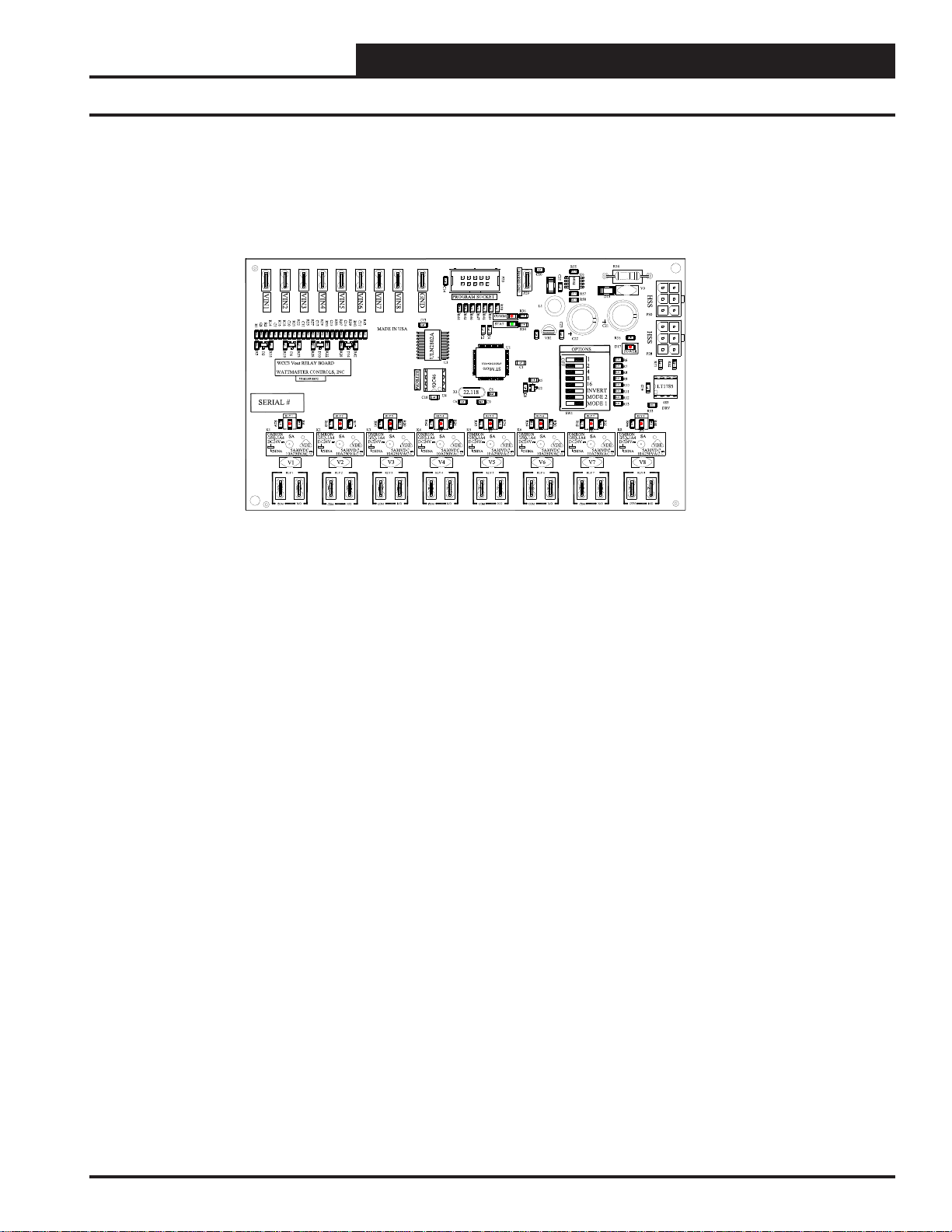
WCC3 Vout RELAY BOARD
WATTMASTER CONTROLS, INC
SERIAL #
RLY1
R59
K1
OMRON
SA
G5Q-1A4
DC24V
5A30VDC
CHINA
10A250VAC ~
NC NO
V1
P2 P3 P4 P6
COM
CHASSISGND
P20
R50
R44
R45
R46
K5
R36
R47
R48
R49
COMM
STAT
R34
C2C3C4
U1
C1
C5
C9
R26
R63
K6 K8
D7
RLY5
COM
GND
C13
ULN2802A
EEPROM
93C46
C18
R62
R20
K4
RLY4
P10
COMCOM
C14
PROGRAM SOCKET
U3
X1
U4
C6
R24
D5
P12 P13 P14 P16
VIN8
VIN7
VIN6
VIN5
VIN4
VIN3
R43
R33
R22
R25
R27
R29
R37
R39
C12
C15
C16
C17
R31
C11
R23
YS102058 REV3
R4
VDE
OUT
R41
MADE IN USA
D14
R32
R28
D10
R38
R42
R60
R17
R61
K2
K3
D4
NC NO NC NO NC NO NC NO NC NO NC NO NC NO
V2 V3 V4 V5 V6 V8
RLY2RLY1
COM
RLY3
P7 P9
OUT OUT OUT OUT OUT OUT OUT
R55
C25
C20
U6
P29
C8
R64
COM
R57
R58
L1
C23
VR1
C22
OPTIONS
1
2
4
R5
U2
RLY6
8
16
INVERT
MODE 2
MODE 1
SW1
R30
R65
D11
V7
RLY7
P19
P17
COM
D15
C21
R56
D17
POWER
R6
R7
R8
R9
R10
R11
R12
R13
RLY8RLY7RLY6RLY5RLY4RLY3RLY2
R35
R66
D13
RLY8
P21 P23 P40
COM
V9
HSS
P30
HSS
P28
R51
R52
C19
485
DRV
R53
R40
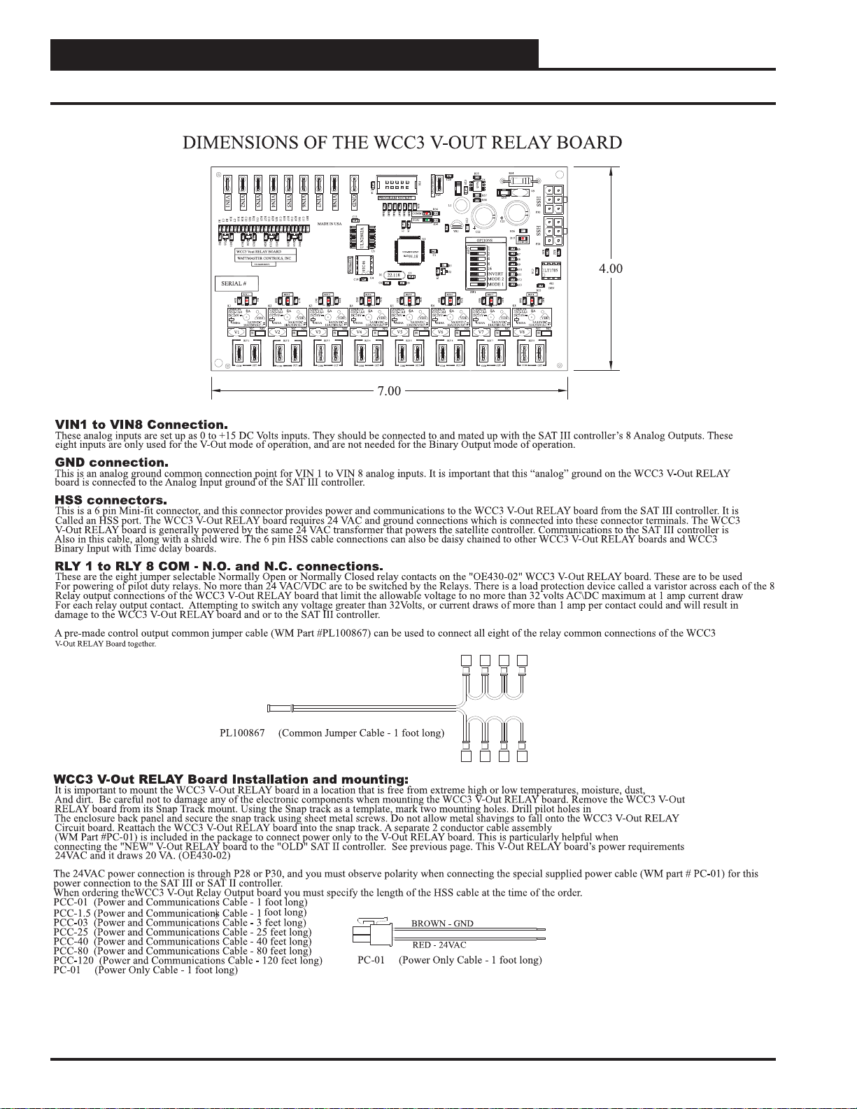
WCC3 V-Out RELAY board Sequence
There are two modes of operation for the WCC3 V-Out RELAY board. One is the V-Out mode and the other is the Binary Output mode.
The WCC3 V-Out RELAY (OE430-02) board has eight relays each with a jumper selectable N.O. (Normally Open) or N.C. (Normally Closed) contacts. These relay
Contacts are rated for 1 Amp at 24VAC/VDC operation only. This WCC3 V-Out RELAY board connects to the HSS expansion port on the side of the SAT III controller. The
WCC3 V-Out RELAY board is an expansion board that allows for another 8 binary outputs (Relay Contacts) to be used with the SAT III controller. Up to three of these
WCC3 V-Out RELAY boards may be connected to the SAT III HSS expansion port. Two boards in the Binary Output mode are supported, and one board in the V-Out
Mode is supported. One HSS expansion board will add 20 VA of VA load to the SAT III power requirement.
These eight Analog Inputs connections must be connected to the eight Analog Outputs of the SAT III controller in the V-Out mode of operation. These analog values are
not digitally transmitted via the HSS port on the SAT III to the WCC3 V-Out RELAY board in the V-Out mode.
There is a load protection device called a varistor across each of the 8 relay output connections of the WCC3 V-Out RELAY board that limit the allowable voltage to no
More than 32 volts AC\DC maximum at 1 amp current draw for each relay output contact. Attempting to switch any voltage greater than 32Volts, or current draws of
more than 1 amp per contact could and will result in damage to the WCC3 V-Out RELAY board and/or to the SAT III controller.
The connecting HSS cable is available in 1 ft., 1 / ft , 3 ft., 25 ft., 40 ft., 80., and 120 ft. Lengths.
The Dipswitch on the WCC3 V-Out RELAY board
Dipswitch SW1-7 (MODE 2 - V-Out Mode) and SW1-8 (MODE 1 - Binary Output Mode) selects the MODE of operation for the WCC3 V-Out RELAY board.
If both MODE (SW1-7 and SW1-8) switches are OFF then the WCC3 V-Out RELAY board is in Binary Output mode. Binary Output 1 to 8 is selected. If MODE 1
Switch (SW1-8) is "ON" then Binary Output 9 to 16 is then selected. If MODE 2 Switch (SW1-7) is "ON" then the V-Out mode is selected. You must cycle power to
The WCC3 V-Out RELAY circuit board after setting dip switch SW1-8. You may select any other switch setting without cycling power to the board.
SW1-1 (1) (V-OUT MODE - ADDS 1 VOLT TO DEAD BAND)
SW1-2 (2) (V-OUT MODE - ADDS 2 VOLTS TO DEAD BAND)
SW1-3 (4) (V-OUT MODE - ADDS 4 VOLTS TO DEAD BAND)
SW1-4 (8)
SW1-5 (16)
SW1-6 INVERT (V-OUT MODE) (FLIPS CONDITION OF THE RELAY OUTPUTS)
SW1-7 MODE 2 (V-OUT MODE) (V-OUT MODE DEFAULT SETTING ON)
SW1-8 MODE 1 (When changing this switch, you must cycle power to the circuit board)
Binary Output Mode of operation
When the WCC V-Out RELAY board is set for the Binary Output mode (SW1- switch # 8 is either "ON" or "OFF" and SW1 - switch #7 is "OFF") the eight relays of the
WCC V-Out RELAY board are controlled by the WCC III program setup of the SAT Binary Output screens for each satellite controller. SW1- switch # 8 “OFF" is
Binary Output board address relays 1 to 8, and SW1- switch # 8 “ON" is Binary Output board address relays 9 to 16. This assumes that SW1 - switch #7 is "OFF".
V-Out Mode of operation
When the WCC V-Out RELAY board is set for the V-Out mode (SW1- switch # 7 "ON"), the relay output will turn "ON" when the input voltage rises above 7.5 VDC
(+/-.25V) plus the dead band setting that is determined by Sw1 settings. When the WCC3 V-Out RELAY board is set for the V-Out mode, the relay output will turn
"OFF" when the input voltage drops below 7.5 VDC
for all eight inputs and outputs.
When SW1-1 is selected, 1 volt is added to the dead band. (Dead Band = +/- 1 volts)
When SW1-2 is selected, 2 volts are added to the dead band. (Dead Band = +/- 2 volts)
When SW1-1 and SW1-2 is selected, 3 volts are added to the dead band. (Dead Band = +/- 3 volts)
When SW1-3 is selected, 4 volts are added to the dead band. (Dead Band = +/- 4 volts)
When SW1-3 and SW1-1is selected, 5 volts are added to the dead band. (Dead Band = +/- 5 volts)
The eight analog inputs on the WCC3 V-Out RELAY board must be wired to the eight analog outputs on the SAT III or SAT II controller in order for the V-Out mode to
Function. Also, the HSS connector must be connected to the SAT III HSS expansion port for power and ground connections to the SAT III controller or a special two
wire power and ground pigtail must be provided for connection to 24VAC and GND to power the WCC3 V-Out RELAY board.
(Hysteresis is added to the Setpoint via setting of the SW1 Dipswitch)
1
2.
No more than 150 ft. of total wire can be used to power a SAT III HSS loop.
Sets the various modes of operation, and dead band in the V-Out mode.
(V-OUT MODE DEFAULT SETTING ON)
(+/- .25V) minus the dead band setting that is determined by SW1 dipswitch settings. These dipswitch settings apply
(DEFAULT)
WCC III Technical Guide
16-5
Page 8

16. WCC III V-OUT RELAY BOARD INSTALLATION
OE430-02 Installation
SATIII CONTROLLER CONNECTION FOR A
BINARY OUTPUTTYPE CONNECTION.
0-15VDC
OUTPUT
MIN LOAD
IS 1K OHM
RESISTIVE
VDC ONLY
EACH CONTACT
IS RATED FOR
24VAC ORVDC
@ .5AMPMAX
WCC3 V-OUTRELAY
N.O./N.C. CONTACTS
(OE430-02)
CONNECTION FROM A SAT III CONTROLLER TOWCC3 V-OUT RELAYBOARD USING THE "NEW" HSS CABLE CONNECTION METHOD
SAT III CONTROLLER
+V
ATI
ON OFF
BATTON/ OFF
ON OFF
ON OFF
ON OFF
PULSE INPUT
OPTION 3
OPTION 2
OPTION 1
LOCALSET DISABLE
LOCALSET
TEST
L16
L15
L14
BINARY
L13
L12
INPUTS
L11
L10
L9
L8
L7
L6
BINARY
L5
L4
INPUTS
L3
L2
L1
128
64
32
16
8
4
2
SATADDRESS
1
GND
2134
CHANNEL
2134
L
O
A
D
GND
V
OUT
5678
567
8
H
COM
C
DAISY CHAIN OUT TO
OTHER WCC3 V-OUT RELAY
BOARD OR TO OTHER WCC3
BINARY INPUTW/TIME
DELAYBOARDS THAT ARE
TO BE CONNECTED TO THE
SATIII HSS
COMMUNICATIONS PORT.
STATUS
SATREC
SAT III
HSS REC
STATUS 1
STATUS 2
STATUS 3
PROGRAMMABLE CONTROLLER
ANALOG INPUT
JUMPER SELECTION
THERM
0TO 1V
0 - 10V
0 - 5V
INPUT
0 - 1V
THERM
0TO 5V
0 - 10V
0 - 5V
INPUT
0 - 1V
THERM
0TO 10V
0 - 10V
INPUT
0 - 5V
0 - 1V
CH
THERM
0 - 10V
1
2
3
4
5
6
7
8
THERMISTOR
0 - 5V
INPUT
0 - 1V
THERM
0 - 10V
CURRENT
0 - 5V
INPUT
0 - 1V
A4TO 20 mA SENSOR WILL REQUIRE A
50 OHM LOAD RESISTORWHEN SETFOR
A1VOLT INPUT, ORA 250 OHM LOAD
RESISTORWHEN SETFOR A 5 VOLTINPUT.
A2WIRE ROOM SENSOR WILL REQUIRE
A300 OHM LOAD RESISTORWHEN SET
FORA1 VOLT INPUT.
A3WIRE ROOM SENSOR WILL NOT
REQUIREALOAD RESISTOR WHEN SET
FORA1 VOLT INPUT.
WattMaster Controls Inc.
SATXMIT
HSS XMIT
LOCALSET
24VAC
WARNING: OBSERVE POLARITY
BETWEEN THE SATIII AND THE WCC3
V-OUT RELAY BOARD - GROUND
CONNECTIONS MUST BE THE SAME.
USING THIS METHOD CAN NOT
DAMAGE EITHER DEVICES.
24VAC
24VAC 120VAC
GROUND
120VAC WIRING IS BY OTHERS
THE VA RATING FOR THE SAT III CONTROLLER IS 15VA.
THE VA RATING FOR THE WCC3 BINARY INPUT BOARD IS 5VA.
THE VA RATING FOR THE WCC3 V-OUTRELAY N.O. BOARD IS 10 VA.(OE430-01)
THE VA RATING FOR THE WCC3 V-OUTRELAY N.O./N.C. BOARD IS 20 VA. (OE430-02)
TO HSS EXPANSION BOARDS.
UP TO TWO WCC3 BINARY INPUT W/TIME DELAY
BOARDS, AND UP TOTHREE V-OUT RELAYBOARDS
MAYBE CONNECTED TO A SATIII CONTROLLER
HSS COMMUNICATIONS PORT.
TO OTHER
SAT III OR TO
WCC III - MCD
TO OTHER
SAT III OR TO
WCC III - MCD
WIRE "T" TO "T"
"R" TO "R"
"SHD" TO "SHD"
DUPLICATINGTHE ORIGINAL SAT II
V-OUTTYPE CONNECTION.
CONNECT ALL EIGHTOF THE SAT III
ANALOG OUTPUTS V-OUT #1 THRU
V-OUT # 8 TO THE "OLD" SATII TYPE
V-OUT BOARD INPUTS # 1THRU # 8.
CONNECT ONE OF THE SAT III GND
CONNECTIONS TO THE "OLD" SAT II
TYPE V-OUTBOARD GND
CONNECTION IF POSSIBLE.
"SAT 2 TYPE" V-OUT BOARD
0-15VDC
OUTPUT
MIN LOAD
IS 1K OHM
RESISTIVE
VDC ONLY
EACH CONTACT
IS RATED FOR
24VAC ORVDC
@ .5AMPMAX
SAT III CONTROLLER
+V
ATI
ON OFF
BATTON/ OFF
ON OFF
ON OFF
ON OFF
PULSE INPUT
OPTION 3
OPTION 2
OPTION 1
LOCALSET DISABLE
LOCALSET
TEST
L16
L15
L14
BINARY
L13
L12
INPUTS
L11
L10
L9
L8
L7
L6
BINARY
L5
L4
INPUTS
L3
L2
L1
128
64
32
16
8
4
2
SATADDRESS
1
GND
2134
CHANNEL
2134
5678
567
L
O
A
D
GND
V
OUT
8
H
COM
C
STATUS
SATREC
SAT III
SATXMIT
HSS XMIT
LOCALSET
24VAC
PROGRAMMABLE CONTROLLER
HSS REC
STATUS 1
STATUS 2
STATUS 3
ANALOG INPUT
JUMPER SELECTION
THERM
0TO 1V
0 - 10V
0 - 5V
INPUT
0 - 1V
THERM
0TO 5V
0 - 10V
0 - 5V
INPUT
0 - 1V
THERM
0TO 10V
0 - 10V
INPUT
0 - 5V
0 - 1V
CH
THERM
0 - 10V
1
2
3
4
5
6
7
8
WARNING: OBSERVE POLARITY
BETWEEN THE SATIII AND THE "OLD"
SATII TYPE V-OUT BOARD.
THE GROUND CONNECTIONS MUST BE
THE SAME. DAMAGE TO THE SAT III
CONTROLLER OR TO THE "OLD" SAT II
TYPE V-OUTBOARD CAN RESULT IN
VOIDING WARRANTY.
THERMISTOR
0 - 5V
INPUT
0 - 1V
THERM
0 - 10V
CURRENT
0 - 5V
INPUT
0 - 1V
A4TO 20 mA SENSOR WILL REQUIRE A
50 OHM LOAD RESISTORWHEN SETFOR
A1VOLT INPUT, ORA 250 OHM LOAD
RESISTORWHEN SETFOR A 5 VOLTINPUT.
A2WIRE ROOM SENSOR WILL REQUIRE
A300 OHM LOAD RESISTORWHEN SET
FORA1 VOLT INPUT.
A3WIRE ROOM SENSOR WILL NOT
REQUIREALOAD RESISTOR WHEN SET
FORA1 VOLT INPUT.
WattMaster Controls Inc.
TO HSS EXPANSION BOARDS.
UP TO TWO WCC3 BINARY INPUT W/TIME DELAY
BOARDS, AND UP TOTHREE V-OUT RELAYBOARDS
MAYBE CONNECTED TO A SATIII CONTROLLER
HSS COMMUNICATIONS PORT.
TO OTHER
SAT III OR TO
WCC III - MCD
TO OTHER
SAT III OR TO
WCC III - MCD
WIRE "T" TO "T"
"R" TO "R"
"SHD" TO "SHD"
24VAC
24VAC 120VAC
GROUND
A CHIPSWITCH MUST BE
PRESENT FOR EACH
OUTPUT TO FUNCTION
CONNECTION FROM A SAT III CONTROLLER TOAN OLD SAT II TYPE V-OUT BOARD USING THE “OLD” HARD WIRED WAY. WIRING THE SAT III CONTROLLER’S V-OUT
CONNECTIONS # 1 THRU # 8 TO THE OLD SAT II TYPE V-OUT BOARD INPUTS VIN 1 THRU VIN 8 CONNECTION METHOD.
120VAC WIRING IS BY OTHERS
THE VA RATING FOR THE SAT III CONTROLLER IS 15VA.
THE VA RATING FOR THE WCC2 V-OUTRELAY BOARD IS 10 VA.
THE VA RATING FOR THE WCC3 V-OUTRELAY N.O. BOARD IS 10 VA.(OE430-01)
THE VA RATING FOR THE WCC3 V-OUTRELAY N.O./N.C. BOARD IS 20 VA. (OE430-02)
16-6
WCC III Technical Guide
Page 9

16. WCC III V-OUT RELAY BOARD INSTALLATION
OE430-02 Installation
WCC III Technical Guide
16-7
Page 10
16. WCC III V-OUT RELAY BOARD INSTALLATION
OE430-02 Installation
16-8
WCC III Technical Guide
 Loading...