

Page 1
13B. WCC III - MCD2
Installation Guide
WCC III
13B. WCC III - MCD2
Installation Guide
Page 2

T ABLE OF CONTENTS
SECTION 13B: WCC III - MCD2
INST ALLA TION GUIDE
__________________________________________
Main Differences Between the First Generation
WCCIII-MCD and the New WCCIII-MCD2
Computers ................................................................ 13B-2
The WCCIII-MCD2 Basic Operating Conditions ..... 13B-5
WCCIII-MCD2 Basic System Requirements ........... 13B-5
Front End Software Requirements
(Operator Console Software) .................................. 13B-5
Uninterruptable Power Supply ............................... 13B-6
Basic Operating Conditions of the MCD2 .............. 13B-6
Software Updates .................................................... 13B-6
WCCIII-MCD2 Internet Access ................................ 13B-6
RS-485 Communications Wiring ............................. 13B-7
WCCIII-MCD2 Mounting Requirements .................. 13B-8
Power Supply (24V A C) R equirements .....................13-10
Test DNS Settings (Choice #8) ........................ 13B-29
Update MCD2 via USB (Choice #9)..................13B-29
Update MCD2 via NET (Choice #10) ................ 13B-29
Reset MCD to Default IP Address
(Choice #11) ...................................................... 13B-30
Reset MCD to Default DNS Settings
(Choice #12) ...................................................... 13B-30
Restart LCD Driver (Choice #13) .....................13B-30
Restart LCD Display (Choice #14) ................... 13B-31
Shutdown MCD (Choice #15) ........................... 13B-31
Shutdown and Reboot the MCD
(Choice #16) ........................................................ 3B-31
How to Use the Initial Install and Reco v ery
Program on the WCCIII-MCD2 with the
install-menu program .......................................13B-32
Setup New CrystalFontz 635 Display
(Choice #1) ........................................................ 13B-33
Restore Backtask DAT Files from
CompactFlash (Choice #2) ............................... 13B-33
Initiating the System ............................................. 13B-11
WCCIII-MCD2 System Files ................................... 13B-11
Various I/O Connections ........................................ 13B-12
WCCIII-MCD2 LCD Screen ..................................... 13B-15
The LCD’s Keypad .................................................. 13B-15
WCCIII-MCD2 LCD Screens ................................... 13B-16
BIOS Confi guration for the WCCIII–MCD2.............13B-19
Linux Operating System Software Installation
Procedure ............................................................... 13B-19
WCCIII-MCD2 On/Off/Shut Down/Reset
Buttons ................................................................... 13B-19
Setup Time Zone (Choice #2) ............................... 13B-25
Copy the Backtask Data Files to USB Driv e
(Choice #3) ............................................................. 13B-26
Restore BackT ask data Files to USB Driv e
(Choice #4) ............................................................. 13B-27
Test APC UPS Connection (Choice #5) ................ 13B-28
Apply USB Over-Current HOTFIX and Reboot
(Choice #3) ........................................................ 13B-33
Reset {APCUPSD/Webmin/Firewall/LCDd}
to Default Settings (Choice # { 4/5/6/7 } ) ........ 13B-33
Create New SSH Server Keys
(Choice #8) ........................................................ 13B-33
Shutdown and Reboot the MCD
(Choice #9) ........................................................ 13B-33
How to Access the Linux-Based Functions
of the Operating System of the
WCCIII-MCD .......................................................13B-34
Common Linux Commands that would be
helpful to know for the WCCIII-MCD2 ..............13B-37
The WCC III – MCD Remote Serial Console .... 13B-40
Null Modem cable ............................................. 13B-41
WCCIII-MCD2 Backup/Restore Data to
and from USB Drives ........................................13B-43
WattMaster Controls - Ubuntu Linux
Installation ........................................................13B-44
Restart APC Monitor Server (Choice #6) ............. 13B-29
Test Internet Connection (Choice #7)...................13B-29
Page 3

13B. WCC III - MCD2 INSTALLATION GUIDE
System Requirements
SECTION 13B: WCC III - MCD2
INST ALLA TION GUIDE
__________________________________________
WCC III - MCD2 History Information
The WCCIII-MCD2 (WM part # OE405-02) was designed as
a product improvement of the older WCCIII-MCD (WM part #
OE405-01) and as such is a drop-in replacement unit for the older
WCC III-MCD computer product (WM Part # OE405-01). The
original WCCIII-MCD was designed as a product improvement
upgrade for the old WCCII type computer .
The heart of the WCCIII-MCD2 is an industrial-rated single board
computer that is within a custom-designed wrap-around sheet
metal computer enclosure that matches the look of the satellite type
3 controllers, and this makes the new WCCIII-MCD2 about one
quarter the size of the previous WCCIII-MCD. It has completely
quiet operation due to the fact that the new WCCIII-MCD2 is
completely fanless due to far less power requirements of the newer
generation of Intel
TM
processors.
The WCCIII-MCD2 is powered off of a single 24VAC @50VA
transformer (WM part # WP000050) – that is supplied with the
WCCIII-MCD2.
Also the new WCCIII-MCD2 uses a lot less separate individual
components in its construction than the old WCCIII-MCD
computer.
The old WCCIII-MCD used 7 separate cable assemblies to
interconnect the various circuit boards with in the WCCIII-MCD
case to each other. The new WCCIII-MCD2 uses a single cable
assembly called “SBC INTERNAL I/O CABLE” (WM part #
HZ00160) to interconnect the various circuit boards together.
There used to be a separate circuit board on the old WCCIII-MCD
that was used to control the power startup/shut down functions. On
the new WCCIII-MCD2, these power start up/shut down functions
are now handled by the CrystalFontz LCD controller. There was
also a passive backplane board on the old WCCIII-MCD, and this
was eliminated on the WCCIII-MCD2 design. The old WCCIIIMCD case used 17 separate pieces of steel sheet metal in its
design, whereas the new WCCIII-MCD2 has two simple pieces of
lightweight aluminum for its case design.
There are no physical moving parts within the WCCIII-MCD2.
WattMaster uses the start up and shut down operational control
of this new WCCIII-MCD2 design with the addition of a 4 line
by 20 character CrystalFontz LCD controller board. In addition,
WattMaster Controls has developed an additional circuit board
called the MCOMM board, which is a PIC32 based 4 channel –
Isolated RS-485 communication packetizer and unpacketizer for
the WCC III satellite type of communications loop.
The WCCIII-MCD2 will communicate to up to 240 of the
WattMaster Controls SAT 3 series of fi eld programmable
controllers. Also, a very specialized, small and compact power
supply module was designed to supply +12VDC @ 4 Amps
power to the MCOMM board, PCM-9362N CPU board, and the
CrystalFontz LCD controller, and this power supply module is
called “LTM8027 Power Supply Module”.
WCC III Technical Guide
13B-1
Page 4

13B. WCC III - MCD INSTALLATION GUIDE
Main Differences Between MCD and MCD2
Main Differences Between the First Generation WCCIII-MCD and the
New WCCIII-MCD2 Computers
First generation WCC III-MCD (See Note 1) New WCCIII-MCD2
120VAC power supply with Power Supply Fan 24VAC power supply (50VA transformer supplied) – Fanless operation.
(This dedicated 24VAC Transformer offers an extra layer of Electrical
Isolation that the fi rst generation WCC III-MCD did not have.)
Intel “M” processor
Wall mounted big bulky case with chassis mounted Fan W all mounted enclosure, Designed with the smallest possible foot print.
The three fans that were used on the fi rst generation of
WCC III-MCD, when combined made a lot of noise.
2 line by 20 character liquid crystal display that displayed 4 line by 20 character liquid crystal display Module with keypad and four
Linux Ubuntu (V8.04 LTS) operating system (See Note 2) Linux Ubuntu operating system (V12.04 L TS)
Main hard drive – Older T ech IDE solid state hard drive. Main Hard Drive - Newer T echnology “SATA” solid state hard drive.
Backup data hard drive - Compact Flash 2Gig Backup data hard drive - Compact Flash 4Gig
“BackTask” program running in windows emulation mode. The “BackTask” program is now running in native Linux.
RS-485 Communications:
Two Isolated RS-485 Communications loops - Standard (Two more
RS-485 Communications loops were optionally available for an
additional cost) (Limited to 60 Sats per Loop - 240 Sats Max)
One Ethernet port. (Referred to as “eth0”) Two Ethernet ports. (Referred to as “eth0” and “eth1”)
Four external USB ports. Four external USB ports.
UPS Backup power loss method
24VAC transformer used for detection of loss of power.
The onboard power switch board would detect loss of
power and then shutdown the WCCIII-MCD
TM
with CPU Fan Newer generation Intel “Atom Processor”TM Passive cooling – Fanless
Completely Fanless operation. Also this new WCCIII-MCD2 enclosure
intentionally matches the look and feel of the aluminum enclosures for
the SAT III, and Sat 3 C/D/E/F controllers
additional “Status” LEDs. This LCD Module also integrates all of the
necessary control signals for the ATX power supply functionality for the
WCCIII-MCD2.
RS-485 Communications:
Four Isolated RS-485 Communications loops are provided - Standard.
(Limited to 60 Sats per Loop - 240 Sats Max)
One of these two Ethernet ports (eth1) is used as a fi xed local IP address
for direct connection to a local on site computer, and or a setup Laptop/
Desktop computer for simplistic setup. The other Ethernet port “eth0” is
intended to be connected to the end customer’s network/internet/router.
USB connection to APC
shutdown. This feature adds important information about the exact time
date, and duration logging of the specifi c power outage. See Note 3.
TM
brand Smart UPS for automatic controlled
Table 13B-1: MCD vs. MCD2
13B-2
WCC III Technical Guide
Page 5

13B. WCC III - MCD2 INSTALLATION GUIDE
Main Differences Between MCD and MCD2
NOTE 1
The fi rst generation WCC III - MCD platform was by nature a work in progress, which due to unforeseen circumstances, the following was replaced and/or upgraded
over time: (Also See NOTE 2.)
Conventional spinning Hard Drive – W as replaced by a 4 gig solid state IDE hard Drive.
3 ½ inch Floppy Drive - W as replaced with a 2 by 20 line LCD display.
No data backup drive - W as replaced by a compact fl ash drive with nightly and monthly automatic data backups.
65 W att Power supply - Was Replaced with a 150W power supply. Original Power Supply was not enough.
This fi rst generation WCC III - MCD platform started out as a W indows XP based system, and then over time the fi rst generation WCC III - MCD has been upgraded to
the Linux Ubuntu operating system, which over time became the upgraded WCCIII-MCD. Windows XP operating system required that a keyboard/mouse emulation
box to be attached to the fi rst generation WCC III – MCD, or else certain errors could occur . Windows pretty much requires a Keyboard to function. (Mainly this had
to do with the “Auto-detect” of devices that are connected, and when a keyboard is not detected at some one of sacred fi les would get corrupted, and then cause failure
to boot up issues.) The Windows XP operating system was very susceptible to viruses, and required anti-virus software to be installed, but the antivirus software caused
almost as much problems with continual anti-virus updates, and yearly renewal issues. (The Linux operating system is much less prone to viruses) The Windows XP
operating system was obsoleted by Microsoft, and at this point there is no long term support for this Windows XP operating system anymore.
NOTE 2
The fi rst generation WCCIII-MCD (Referred to in this document as the old WCCIII-MCD) started life out as a Windows XP based system, and over time the fi rst
generation WCC III - MCD has been upgraded to the Linux Ubuntu operating system. At this time the “BackTask” program was written so that it required that it be
running under the Widows operating system, so the fi rst generation WCC III - MCD had the necessary Linux fi les installed so that the “BackTask” program could
be ran under the windows operating system in emulation mode from within the Linux operating system. This emulation mode also used up some 384 meg of main
hard drive space. The new WCCIII-MCD2 has the Linux Ubuntu operating system (V12.04 LTS), but without the windows emulation fi les, because the “Backtask”
program has now been rewritten so that it is running natively in Linux without having to run it in the Linux windows emulation mode.
Before starting the assembling of any WCC III-MCD2, please get the latest and greatest parts lists from Solomon (OE405-02).
All of the parts needed for the building to the required quantities of WCC III-MCD2 should be pulled fi rst, and then the shortages ordered, and then these shortages
should be fi lled before further proceeding in any assembling process.
NOTE 3
There is also a software provision within the WCCIII-MCD2 to control the shutdown of the WCCIII-MCD2 via USB commands that are sent from an APC
UPS (Uninterruptible Power Supply) upon detection of loss of power. When the battery in the UPS drops to 3 minutes of remaining power, the MCD will auto shut
down. A USB cable must be connected between the APC
be made to any of the four USB ports on the WCCIII-MCD2. This USB cable is supplied by APCTM in the box with the UPS.
WattMaster Controls recommends the following USB connected APCTM brand Uninterruptible Power Supplies:
The APC brand UPS must be a minimum of 500VA (300 Watts) and must have a USB connection. A short 1 foot extension cord may also be required to connect the
WCCIII-MCD2’s wall mounted transformer to the UPS in order to utilize all of the other UPS’s power plugs.
APCTM Back-UPS, Models 550/650/750 (550VA Part # BE550G), (650VA Part# BE650G1), (750VA Part # BE750G).
APC Power-Saving Back-UPS Pro 700 - Part # BR700G
APC Power-Saving Back-UPS Pro 1000 - APC Part # BR1000G
APC Smart-UPS 750VA LCD 120V – APC Part # SMT750
TM
APC
is a wholly own trademark of American Power Conversion.
TM
brand UPS and the WCCIII-MCD2 for this to occur. This USB connection cable from the APCTM UPS can
TM
brand
Table 13B-1, continued: MCD vs. MCD2
WCC III Technical Guide
13B-3
Page 6
13B. WCC III - MCD INSTALLATION GUIDE
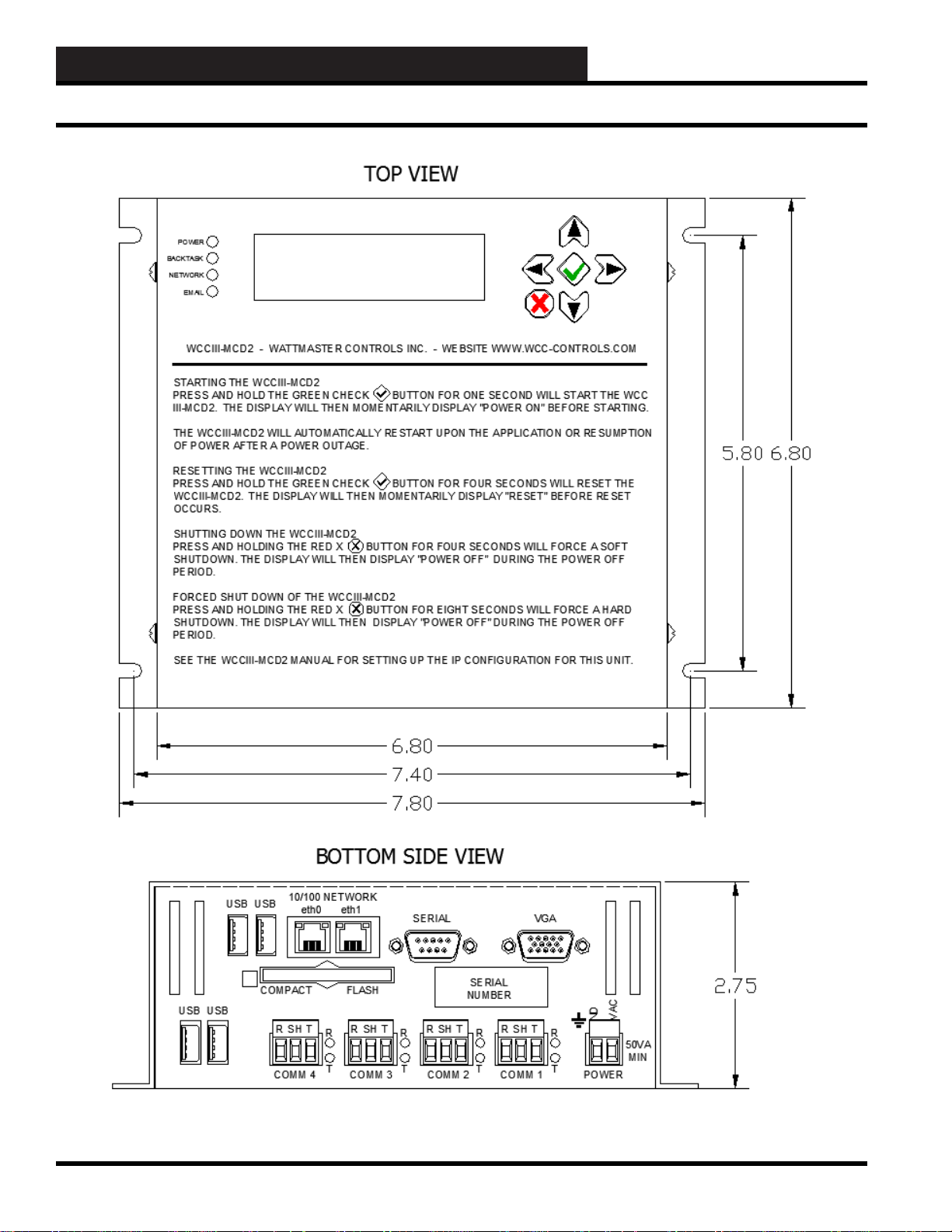
MCD2 Dimensions
Figure 1: MCD2 Dimensions In Inches
13B-4
WCC III Technical Guide
Page 7

13B. WCC III - MCD2 INSTALLATION GUIDE
System Requirements
To accomplish remote communications via the internet, the
following items are needed in addition to the WCC III system in
order to control the building mechanical systems:
WARNING: The WCC III-MCD2 system is not to be used in
any application where Fire/Life/Safety is an issue.
The WCCIII-MCD2 Basic Operating
Conditions
The WCCIII-MCD2 must be kept in a clean and dry area in the
building. The ambient temperature must be between 50 and 100
°F, and the relative humidity must be kept between 0 and 90%
(non-condensing).
The WCCIII-MCD2 is primarily designed to mount on a wall.
The WCCIII-MCD2 computer requires 115 VAC power and must
remain powered at all times for proper operation and control. The
115 VAC power circuit must be separate and dedicated exclusively
to the WCCIII-MCD2 computer. An APCTM brand UPS with an
USB connection must also be connected to the to the WCCIIIMCD2 for backup power.
A dedicated Network IP Address or Domain Name is required.
WCCIII-MCD2 Basic System
Requirements (On-Site WCCIII-MCD2
Computer)
• DSL or a Cable router/switch that connects to the
internet. Or, as an alternative, an internal jobsite
IP network that does not connect to the internet,
but when using this internal jobsite IP network, the
external internet Email of alarms from the WCCIIIMCD2 will not be possible. Also, external access
via the internet may not be possible. An Ethernet
crossover cable is supplied for standalone nonnetwork applications.
• A fi xed static IP address or a fi xed IP domain host
name from the ISP along with a provisioning sheet
that contains other pertinent IP setup information.
• Enabled port forwarding on the Firewall of the
router/switch. This is only if a Firewall is used.
• An Email address that supports a SMTP
server for SENDING with a pop server for
RECEIVING Emails, and it must have “authlogin”
authentication—TLS or SSL modes are supported.
W attMaster Controls can provide an Email address
with these requirements.
• An APC
Supply (UPS) – 700 Watt minimum with USB
communications.
TM
brand Uninterruptible Power
• A wall mounting surface is desirable, and preferred.
• A dedicated 120VAC power circuit is required.
Front End Software Requirements
(Operator Console Software)
• A Microsoft Windows XP /Vista/Windows 7/
Windows 8 -based computer.
• Minimum hardware specifi cation for the Microsoft
Windows XP / Vista based computer is a Pentium
IV running at 2.4 Giga Hertz with at least 1 GB
of RAM, and 10 GB of spare hard drive space. A
CDROM/DVD drive is also required for software
installation.
• WCC III software package – Provided on a
CDROM (W attMaster Part # DM1WC011-01X,
were “X” = revision level), or is available via a
download on the WCC Controls website: www .
wcc-controls.com. The installation CDROM
contains the following programs:
WCC III.exe (SS5021)
WCCUTILITY .exe (SS5023)
SCUSCR.exe (SS5026)
WCC3Trendlog.exe (SS5028)
TenantReport.exe (SS5025)
TenantOverride.exe*(SS5024)
WCC3Download.exe (SS5030)
WCC3Guest.exe (SS5022)
*NOTE: The TenantOverride.exe program is also
available as a single program installation for the
end users that are using the simplistic graphical
interface of the TenantOverride.exe screen to
locally turn on and off specifi c control points that
are applicable to the end user.
• A DSL or Cable router/switch that connects to the
internet, or access to the internet via some other
method. Or, as an alternative, an internal jobsite IP
network that does not connect to the internet, but
when using this internal jobsite IP network, the
external internet Email of alarms from the WCCIIIMCD2 may not be possible.
WCC III Technical Guide
13B-5
Page 8

13B. WCC III - MCD INSTALLATION GUIDE
System Requirements
Uninterruptable Power Supply
The WCCIII-MCD2 system is designed to automatically restart
after a power failure. However, the industrial computer which
acts as the WCC III-MCD2 Master Communications Device will
not automatically reboot unless the power is shut off cleanly and
then restored cleanly. During most power outages, the incoming
115 AC voltage could have great fl uctuations before the power
fi nally fails. In a like manner, brownouts will usually cause the
industrial computer to “lock-up.” That is to say, the screen will
continue to display on the monitor, but the cursor will not respond
to the keyboard commands. To prevent this “lock-up” issue from
happening to the WCC III-MCD2, an Uninterruptible Power
Supply (UPS) is required on each and every WCCIII-MCD2
computer.
An Uninterruptible Power Supply (UPS) provides emergency
power to keep the WCC III-MCD2 Master Communications
Device (personal computer) on-line for several minutes after a
primary power failure. The UPS regulates the incoming power
to the computer and shuts the power off cleanly several seconds
after the power outage, or brownout. When the primary power
is restored, the UPS brings the WCCIII-MCD2 back on-line
automatically. The WCC III system does not lose any information
since all of the programs and user entered data are stored on either
a disk in the MCD, on fi rmware, or on battery backed memory in
the satellite controllers.
Software Updates
WCC III-MCD2 program updates will be made available using
USB “jump” drives and/or internet downloading.
NOTE: As of September 1, 2009, all WCCIII-MCDs will only
be shipped with the Linux operating system installed. Older
Windows XP-based WCCIII-MCDs should be upgraded for
any future support issues from WattMaster. The Windows
XP operating system is at the end of long term support with
Microsoft. Microsoft’s main issues are with continuous
updates, and the multitude of viruses that are written for
Windows XP are also of concern. The Linux operating system
software on the WCCIII-MCD2 must be maintained and
updated periodically. W attMaster Controls, Inc. can do these
software updates and upgrades remotely via the internet only
if the WCCIII-MCD is connected to the internet. This is why
internet access to the WCCIII-MCD2 is so important. Failure
to keep the operating system updated could result in a WCC
III-MCD2 system malfunction. WattMaster Controls, Inc. is
not responsible for a system failure that is so generated due to
lack of upgrading or updating because the end customer does
not provide a static IP connection for the WCC III - MCD2 to
the internet for W attMaster Controls to connect to.
Basic Operating Conditions MCD2
(Master Communications Device)
The WCCIII-MCD has the following specifi cations:
• A Single Board Computer in a custom wall
mounted case
• Processor - Intel
Core
®
Atom™ processor N450 Single
• Memory – 1 GB SODIMM
• Hard Drive – Solid State SATA 8 GB Hard Drive.
Plus a 2 GIG COMPACT FLASH drive for secure
data backup.
• 4 line by 20 character Dot Matrix LCD display
with ATX shutdown control.
• Required I/O
1 - External RS232 port (9 Pin connector)
4 - External USB ports
2 - Internal USB ports
2 - Ethernet Port
WCCIII-MCD2 Internet Access
The most common question asked is: Why does the WCCIIIMCD2 computer need to have Internet access?
• If WattMaster Controls factory assistance or
troubleshooting is required for a WCC III system,
a representative from the factory can access the
system with a remote computer and view the same
WCC III Screens as the end user or contractor
in the building. This allows the end user or the
contractor for the building installation to talk to the
factory representative while they are both viewing
the same screens.
• The Emailing of important alarm notifi cations for
up to 60 Email Addresses is provided for from the
WCCIII-MCD2 device.
• The ability to send alarm notifi cation via a text
message to a cellular phone.
• Secure Remote communications package (WCC
III software) is provided for FREE. A CD-ROM is
supplied for installation.
• W orld-wide, multiple remote connections (up to
255 simultaneous connections possible)
• The ability for internet based tenant override
requires internet access.
13B-6
WCC III Technical Guide
Page 9

13B. WCC III - MCD2 INSTALLATION GUIDE
RS-485 Communications Wiring
The WCC III System RS-485
Communications Wiring
The WCCIII-MCD2 can communicate with up to 239 satellite
controllers via a two-wire RS-485 communication loop. On
the bottom side of the WCCIII-MCD2 there are four RS-485
communication loop ports that come as standard. Each one of
these communications loop ports can communicate with up to 60
satellites for a total of 120 satellites.
The two-wire RS-485 communication loop should be stranded 2
wire twisted pair of 18-gauge wire with a shield wire, and it also
must be plenum rated were applicable. The use of stranded wire is
mandatory to ensure a good connection with the ¼ inch Sta-Con
connectors which are used to terminate the wires at the satellite
controllers. The RS-485 communication wire does not have to be
run from each satellite controller back to the WCCIII-MCD2, but
rather the RS-485 communication wire can be “daisy-chained,”
which means that only one twisted pair of wires is connected to
each of the WCCIII-MCD2 communications loops. The maximum
allowable length of wire from the WCCIII-MCD2 to the farthest
satellite is 4000 feet per RS-485 communications loop.
NOTE: A length greater than 4000 feet is allowed under
certain circumstances. Consult the factory for assistance if the
communications loop required for your application will exceed
4000 f eet.
The RS-485 wire specifi cations are generally a stranded 18-
gauge - 2 wire twisted pair with shield. 18-gauge stranded wire is
mandatory to ensure a good connection with the ¼ inch Sta-Con
connectors, which are used to terminate the wires at the WCC IIIMCD2 and at the satellite controllers. The old SAT II Manchester
communications loop was supposed to have used a 2-wire twisted
pair with shield, but this was not used in every installation. This
old SAT II communications loop should not be used for the new
SAT III communications loop. A new RS-485 communications
loop should be ran to each new replacement SAT III controller.
The shield wire must be used on the new SAT III controller, as
it provides a “ground” reference for the RS-485 communication
loop. WattMaster Controls sells two versions of 18-gauge - 2-wire
twisted pair with shield communications wire—(1) WattMaster
part #WR-NL-WR-18 which is marked “Network Loop” with
a red stripe for rapid identifi cation. This connection is intended
to run from the WCC III – MCD2 to the SAT III, SAT 3C/D/F,
SA T3P, and then to the next SA T 3 type controllers. (2) W attMaster
part# WR-LL-WG-18 which is marked “Local Loop” with a green
stripe for rapid identifi cation for the TUC loops that run from the
SAT 3C/D/F controllers out to the TUC controllers. “Wire Nuts”
on the RS-485 communications loop should be avoided at all costs.
As an alternative to the “Wire Nuts”, WattMaster Controls has a
Power and Switchable RS-485 communications board, and the
W attMaster part number is PL102224. This Power and Switchable
RS-485 communications board can be thought of as a 24-VAC
power and communication distribution system for the SAT III
communications loop, and this board will aid in initial startup
and future troubleshooting of the SAT III communications loop.
These boards should be used on a fl oor-by-fl oor basis. This Power
and Switchable RS-485 communications board is also available
in a small metal electrical enclosure. The wire that makes up the
communication loop should be shielded. Shielded cable has an
aluminum jacket over the wires that could act as an “antenna”
to carry away any “stray” electrical signals that could interfere
with the communication process. The shield should be grounded
throughout the SAT Loop.
Figure 2: WattMaster Local Loop Wire
Figure 3: WattMaster Network Loop Wire
WCC III Technical Guide
13B-7
Page 10
13B. WCC III - MCD INSTALLATION GUIDE
WCCIII-MCD2 Mounting Requirements
WCCIII-MCD2 Mounting Requirements:
The WCCIII-MCD2 was designed to be wall mounted, and
therefore should be mounted on a wall or in a NEMA 1 rated
electrical enclosure.
The WCCIII-MCD2 should be mounted in an air-conditioned
space (The ambient temperature must be between 50 and 100
°F, and the relative humidity must be kept between 0 and 90%
(non-condensing)). Setting the WCCIII-MCD2 on a desktop is
possible, but not recommended due to top and bottom ventilation
considerations.
Mounting in an NEMA type 1 electrical enclosure is possible
providing that there is enough ventilation and minimum clearance
for ventilation. The height of mounting the WCCIII-MCD2 should
be at eye level or with local codes on compliance with the ADA
act of 1990/2009. A minimum of two inches of clearance should
be maintained all around the WCCIII-MCD2, with the exception
of the bottom side of the WCCIII-MCD2 where four inches of
clearance is required for connector’s clearances.
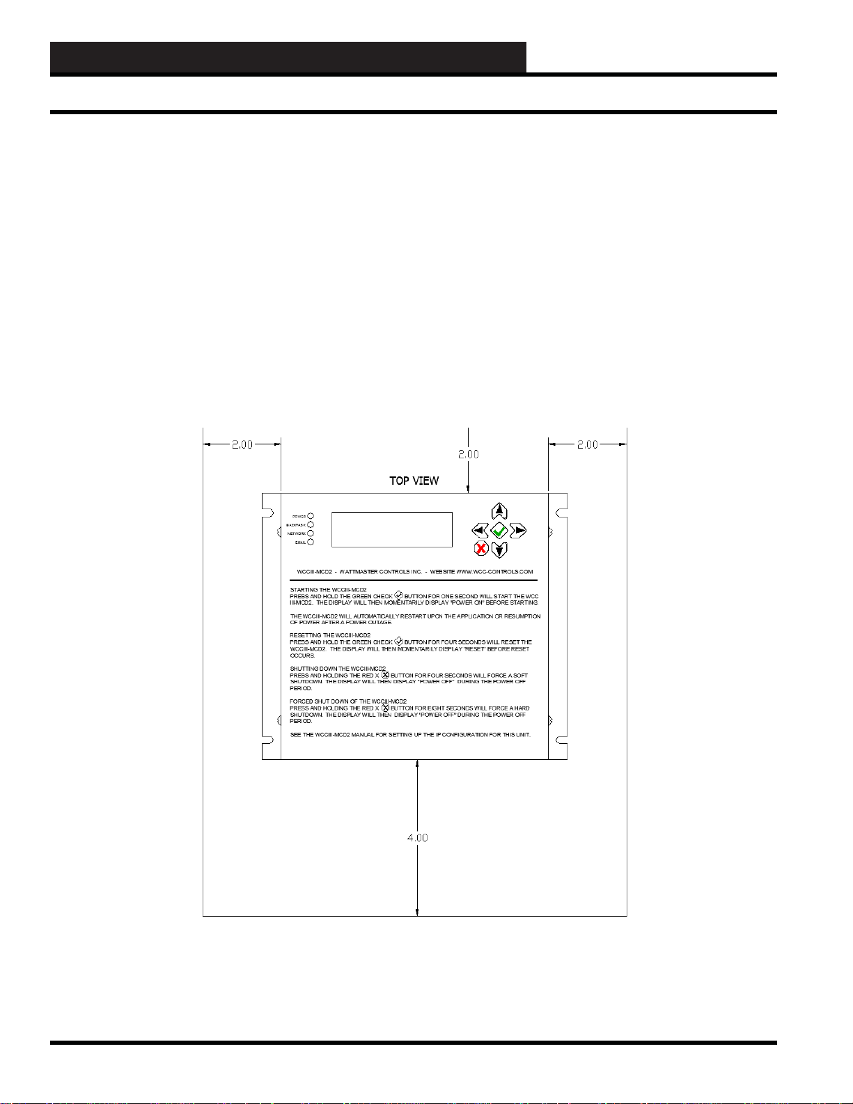
When mounting the WCCIII-MCD2, proper minimum clearance
distances must be met and must be maintained. Space must be
allowed for proper ventilation. When mounting in an electrical
enclosure, be sure that you would avoid mounting the WCCIIIMCD2 above any heat generating sources such as transformers,
and energized contactors, etc. Some thought must be given to the
possibility of adding ventilation to the NEMA 1 rated enclosure
that the WCCIII-MCD could be mounted in if so mounted.
Figure 4: Top View - Minimum Mounting Distance Clearances
13B-8
WCC III Technical Guide
Page 11
13B. WCC III - MCD2 INSTALLATION GUIDE
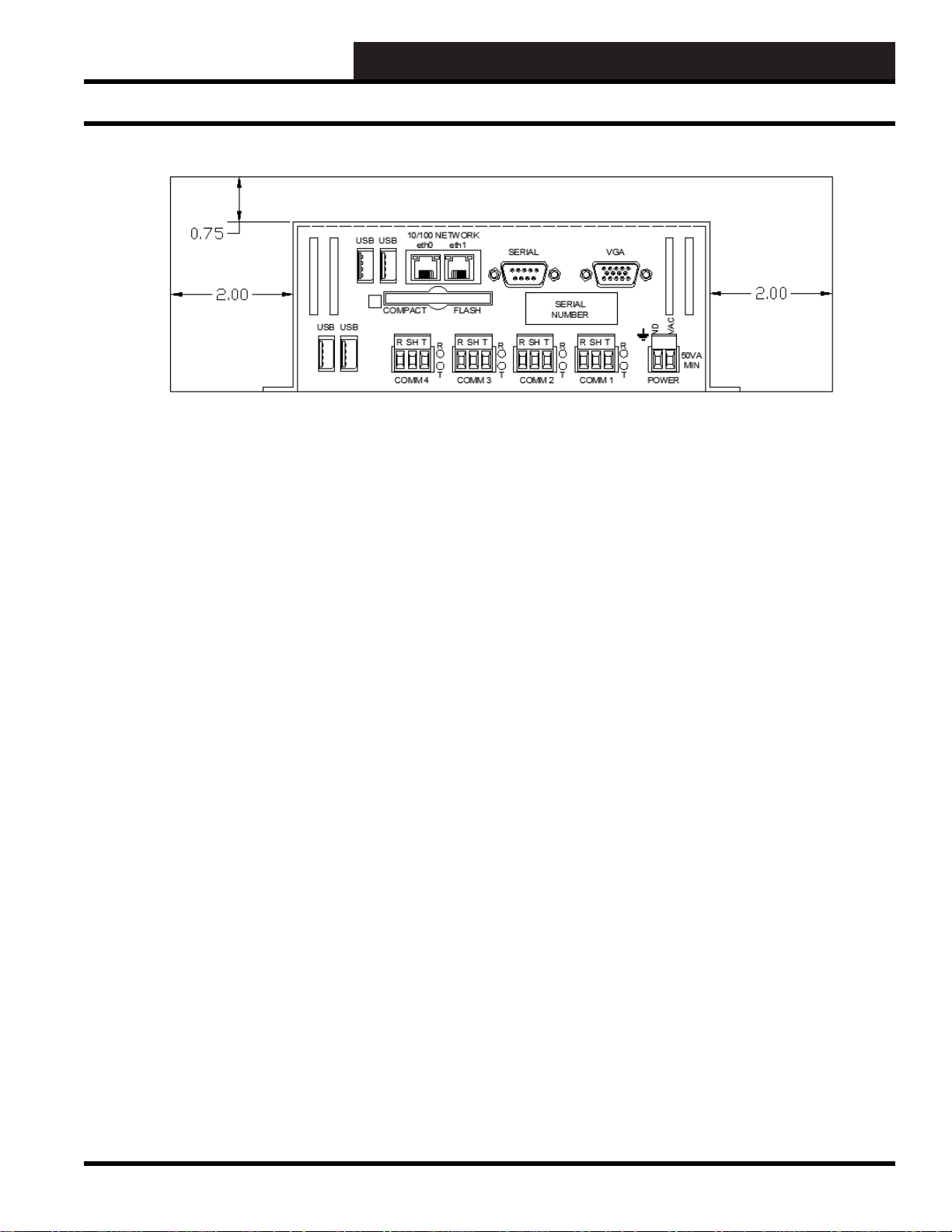
WCCIII-MCD2 Mounting Requirements
Figure 5: Bottom View - Minimum Mounting Distance Clearance
WCC III Technical Guide
13B-9
Page 12

13B. WCC III - MCD INSTALLATION GUIDE
Pow er Supply Requirements
Power Supply (24VAC) Requirements
The WCCIII-MCD2 should only be powered by a dedicated
wall wort type 120VAC to 24VAC @50VA transformer, and this
transformer should only be used to power up the WCCIII-MCD2.
There should be no other devices/controllers that should be powered
off of this dedicated transformer . WattMaster Controls supplies the
WCCIII-MCD2 with such a transformer (WM Part # WP000050).
There is a modifi ed power cord (WM Part # HZ000161) that is
to be supplied with the WCCIII-MCD2’s transformer. There are
two fork terminals (WM Part # SL18RA6F – Fork Terminal,
#6 screw, 18 to 22 Gage) that are used to connect this modifi ed
cable to the 50VA transformer. The other end of this cable is a 2
position de-pluggable type connector (WM Part # GP000136 TERMINAL PLUG - 2 POSITION DEPLUGGABLE). Again
only the WCCIII-MCD2 should be powered from this dedicated
24VAC@50VA transformer. With the use of screw terminals on
the transformer that WattMaster Controls supplies you can easily
change the length of the power cord to up 100 feet. You must use
a minimum of 18 gauge wire (16 or 14 gage wire would be better)
to accomplish this.
If you choose not use the supplied dedicated wall wort type
120VAC to 24VAC @50VA transformer, then an isolation
transformer must be used. The only other option is to use a separate
dedicated transformer (only connected to the WCCIII-MCD2) that
can be connected to the WCCIII-MCD2 device. This transformer
must have an output that is rated for 24VAC @ 50 VA minimum
with appropriate fusing for its size.
The 24VAC@50VA power transformer for the WCCIII-MCD2 is
to be connected to a dedicated APCTM brand UPS ( Uninterruptible
Power Supply) outlet so that the WCCIII-MCD2 will keep
running during a minor power outage. The Cable/DSL modem/
router should also be plugged in to one of these dedicated UPS
(Uninterruptible Power Supply) outlets. Take note that the UPS
may have several outlets but not all are marked backup power.
Some are surge suppression only . Use the backed up power outlets.
The WCCIII-MCD2 has the ability to monitor power status of
the UPS to control the shutdown of the WCCIII-MCD2 via the
supplied APC USB cable. These commands that are sent from an
TM
APC
brand UPS (Uninterruptible Power Supply) upon detection
of loss of power will alert the WCCIII-MCD2 of power failure
that is then logged to the MCD’s SYSLOG fi le. The MCD will
monitor the UPS until there are 3 minutes of power remaining and
then initiate a shut-down of the WCCIII-MCD2. Upon resumption
of normal power, the WCCIII-MCD2 will power up on its own and
log the event in SYSLOG of the OS.
***WARNING*** If not using the supplied 24 V A C @ 5 0V
transformer, you must observe polarity if this other 24 V A C
transformer is connected to other devices. The use of another
transformer is NOT recommended.
Figure 6: Power Supply
13B-10
WCC III Technical Guide
Page 13

13B. WCC III - MCD2 INSTALLATION GUIDE
Initiating the System
Initiating the System
The SAT RS-485 communication loop wires are connected to the
“R” and “T” and shield terminals on the satellite controllers using
¼-inch Sta-Con connectors. Make sure the polarity is correct. That
is to say, the wire connected to the “R” and “T” terminal on the
WCCIII-MCD2 must be connected to the “R” and “T” terminal
on the satellite controllers. If the “R” and “T” and shield wires
are crossed, the WCC III system will not communicate. The shield
should be connected together when the cable is cut in order to
terminate the wires at the satellite controller. The communication
loop wire from the WCCIII-MCD2 is connected to one of the “R”
and one of the “T” terminals on the satellite controller, which is
physically located nearest the WCCIII-MCD2. The other “R”
and “T” terminals located on the satellite controller can be used
to extend the two-wire loop to the next satellite controller, or the
wires can branch off of a two-wire loop running through the center
of a building.
NOTE: The shield wire must be connected at each and every
Satelli te Con troller , also .
After the satellite controllers have been installed and powered
up, the WCCIII-MCD2 set up, and the 2-wire communications
line connected between all of the satellite controllers and also
connected to the WCCIII-MCD2, then the WCC III data fi les need
to be loaded into the WCC III - MCD. This is best accomplished by
using the WCC “mcd-menu” batch fi le, remotely with the Webmin
program, or by directly using the Linux command prompt on the
WCC III-MCD2 VGA monitor/USB Keyboard connections.
This “Webmin” program can be used over the internet/intranet or
locally with a network crossover cable. The “Webmin” program is
pre-installed on the Linux OS hard drive on the WCCIII-MCD2.
There are three password levels for the “Webmin” program, one
for the simple user, one for the contractor level, and one for the
W attMaster factory administrator.
WCCIII-MCD2 System Files
The Backtask program on the WCCIII-MCD2 is stored on the
solid state hard disk, so after boot-up, the system start up fi les will
cause the Backtask Program to run.
CAUTION: The WCCIII-MCD2 will not communicate
with the satellite controllers while it is going through the “reboot” process. If the satellite controllers do not communicate
with the WCCIII-MCD2 for approximately three minutes,
they will go into local set. The time it takes for the system to
“re-boot” should not cause the satellite controllers to go into
local set. The hard disk can hold a vast amount of data which
can accidentally be erased or lost due to system malfunction,
operator error, etc. Therefore it is extremely important to
make a back-up copy of the data on the hard disk. As you
program a system to control a building, information is written
on the disks. Therefore, back-up copi es of programming data
fi les on the hard disk should be made after the system has
been programmed to control the building. This can be done
remotely through the WCC Utility program.
NOTE: When converting the WCC II data fi les to WCC III
type d ata fi les, the WCC II data fi les have to be converted
to the new WCC III type data fi les using the WCCUtilities.
exe program. Then these new WCC III data fi les need to be
installed on the WCCIII-MCD2. This is best accomplished
by using the WCC “mcd-menu” batch fi le, remotely with the
Webmin program, or by directly using the Linux command
prompt on the WCCIII-MCD2.
The WCC III–MCD2 has two solid state hard drives, one that
has the Linux operating system along with the backtask program,
and one that has the daily/monthly WCC III backup data fi les
on it. A USB thumb drive can be used to shuffl e the data in and
out of the WCC III–MCD2. Another program called “Webmin”
is primarily used to administer the more advanced setup features
on the WCCIII–MCD2. This “Webmin” program requires an
internet browser, such as Mozilla, or Microsoft Internet Explorer
to function.
WCC III Technical Guide
13B-11
Page 14
13B. WCC III - MCD INSTALLATION GUIDE
Input/Output Connections
Various I/O connections tha t are on the
Bottom Side of the WCCIII-MCD2 De vice
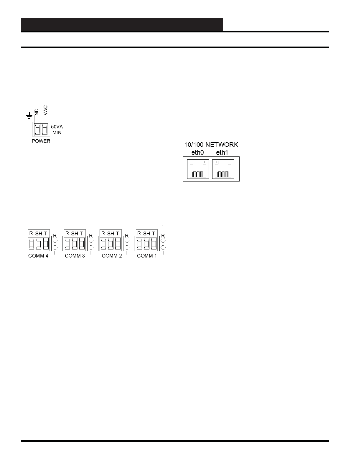
24VA C P ow er Connector
A two position de-pluggable connection is provided for power
connection to the WCCIII-MCD2 device. The WCCIII-MCD2 is
powered off of dedicated 120VAC to 24VAC@50VA transformer
that WattMaster Controls supplies with each WCCIII-MCD2
device. The 24VAC power de-pluggable connector is considered
to be “polarized” with a 24VAC side and a GND side. Correct
power polarity must be observed.
RS-485 Connectors
The WCCIII-MCD2 device provides four separate RS-485
connections. Each one of these three position de-pluggable
RS-485 connections are distance rated for up to 4000 feet of
communications loop cable when using approved communications
wire. (WM Part # or WM Part #). This communications cable is
described as 18 gauge single pair twisted, with a shield, and drain
wire. The Drain wire (Shield) must be connected between the
WCCIII-MCD2 device and all of the Satellite controllers.
R & T COMMUNICATIONS LEDs
There are simplistic communication diagnostic LEDs that are
provided next to each one of the RS-485 connectors. The LED
marked “R” stands for “Receive”, and this red LED will fl icker
when data is received from a specifi c satellite controller. The LED
marked “T” stands for “Transmit” and this red LED will LED will
fl icker when data is transmitted by the WCCIII-MCD2 to a specifi c
satellite controller).
10/100 Network ports eth0, and eth1
The main Ethernet port on the WCCIII-MCD2 is named and
labeled “eth0”. This is the primary I/P connection to the WCCIIIMCD2 device. See page XX for detailed instructions on how to
properly confi gure this network port for proper network access.
The auxiliary (second) Ethernet port on the WCCIII-MCD2 is
named and labeled “eth1”. This port confi guration should never
be changed or reconfi gured by the contractor or end user. It is
meant for direct connection (with a network cross-over cable) to
a Laptop that is to be used for setup, confi guration, updating, and
troubleshooting, or to a dedicated WCC3 computer that would be
set up to run the various WCC3 type programs that connect to the
WCCIII-MCD2 via a network connection.
Each port—etho0 and eth1—has two built in LEDs.
The Left LED is a bi-color Network Speed indicator:
LED Yellow on – Operating as a Gigabit connection (1000 Mbps)
LED Green on – Operating as a 100-Mbps connection.
LED Off – Operating as a 10-Mbps connection.
Wiring between the WCCIII-MCD2 and the satellite
controllers:
Basic rule of thumb when wiring communications from the
WCCIII-MCD2 to any and all Satellite connections: Wire “R”
connections to “R” connections, Wire “T” connections to “T”
connections, Wire “SH( SHLD)” connections to “SH (SHLD)”
connections, and there should not be an issue with communications
wiring.
13B-12
The Right LED is Link/Activity indicator:
LED Blinking – There is activity on this port.
LED Off – There is no network link established.
WCC III Technical Guide
Page 15
13B. WCC III - MCD2 INSTALLATION GUIDE
Input/Output Connections
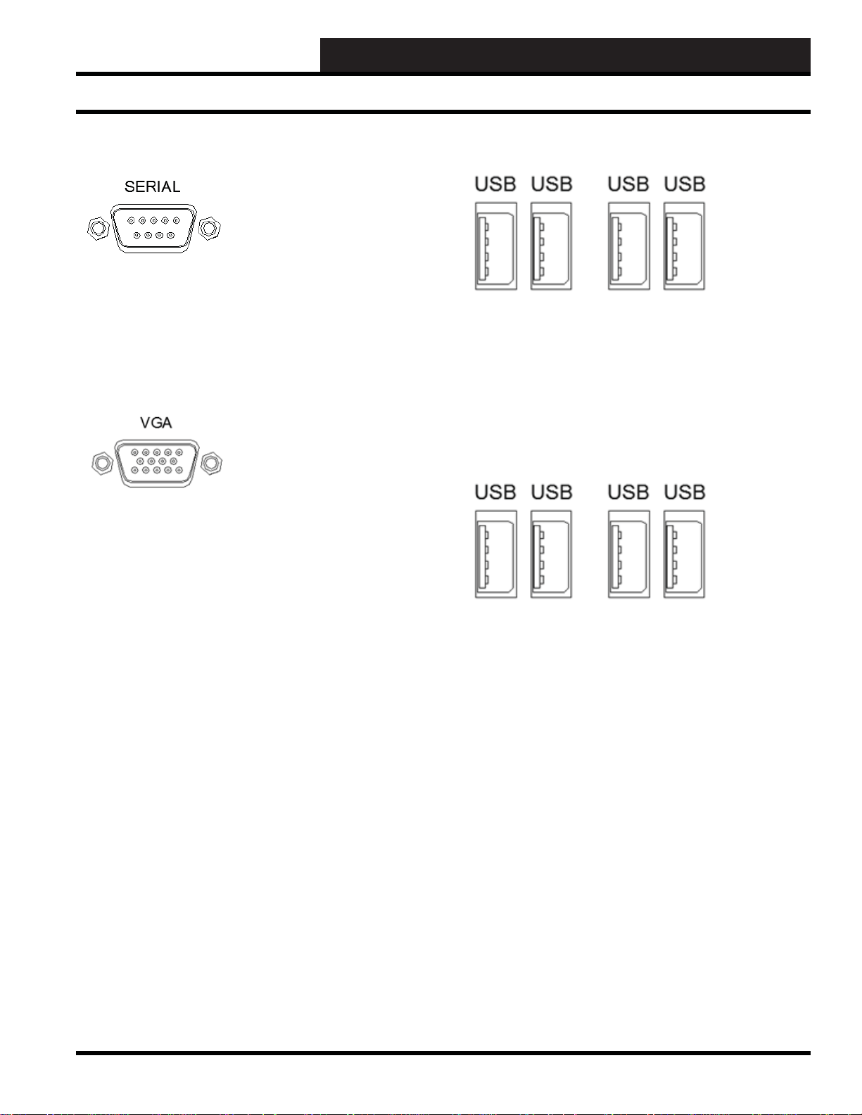
Serial Port
The Serial port is a 9 Pin “AT – Type” port that is now only used
for extreme cases as a point of access in case the Ethernet ports
and VGA are non-functional for some unknown reason. See page
43 for how to connect to a Windows based computer running
Hyper-Terminal for access.
VGA Monitor & USB Key Board
Normal operation of the WCCIII-MCD2 does not require the use
of a VGA monitor and USB Keyboard, but a VGA Monitor and
a USB Keyboard may be required only for initial setup and/or
software updating if you choose not to use a network cross-over
cable, and the putty.exe program to confi gure and or update the
WCCIII-MCD2 device. The Webmin access program should not
generally be used to initially confi gure or update the WCCIII-
MCD2 device.
VGA Monitor & USB Key Board Connections
You may use any of the four external USB connections for the
USB keyboard, and these external USB connectors are located on
the bottom side of the WCCIII-MCD device. A standard 15 pin
VGA monitor will plug into the clearly marked VGA port plug on
the bottom side of the WCCIII-MCD2 device.
USB ports
There are 4 four USB ports provided on the bottom side for
the WCCIII-MCD2 device. These USB ports are meant to be
connected to the following devices: USB Keyboard, USB APC
UPS, and USB Memory stick(s). The USB memory stick is used
for program data backup, data restore, system updates, and system
reloading.
TM
WCC III Technical Guide
13B-13
Page 16
13B. WCC III - MCD INSTALLATION GUIDE
Input/Output Connections
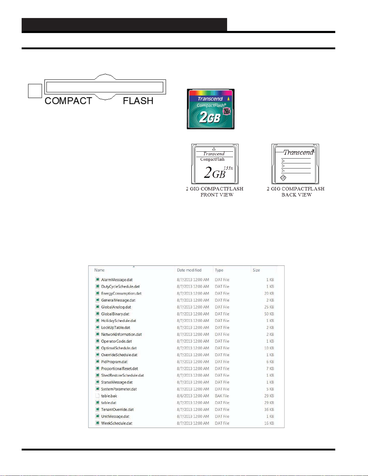
Compact Flash Port
The Compact Flash port on the WCCIII-MCD2 is utilized for
inserting a 2 Gig Memory module that plugs into the bottom side
of the WCCIII-MCD2 device. This Compact Flash connector
is polarized to prevent backwards insertion. This is where the
automatic daily/monthly backups of the WCC III / Backtask data
fi les are stored. This is done for customer backup data safety
purposes. The data is stored on root under an automatically
monthly created subdirectory system that is based on a year/
month.
Below is an example of the various data fi les that are stored on
the Compact Flash Card during the automatic safety backup that
the WCCIII-MCD2 automatically does at midnight every night.
This automatic safety backup occurs at midnight every night and
the previous day’s data is over written. The time listed for of all
of these fi les should be at 12:00 AM. This continually occurs until
the last day of the month when the WCCIII-MCD will automatically make a new subdirectory for the new month.
The WCC III-MCD2 Solid State CompactFlash
Module—2 GIG COMP A CT FLASH (WM Part #
ECC90052)
13B-14
WCC III Technical Guide
Page 17

13B. WCC III - MCD2 INSTALLATION GUIDE
LCD Display
The 4 Line by 20 Character LCD screen
on the WCCIII-MCD2
The CrystalFontz – 4 by 20 line LCD is an end user viewing
interface that is used to show the current status of the WCCIIIMCD2.
This 4 by 20 line LCD display will currently show the following
options:
• IP address (Current IP confi guration for eth0 of the
WCCIII-MCD2)
• System Time (Current time and date of the
WCCIII-MCD2)
• System Uptime WCCIII-MCD2 Uptime (Time
since last reboot)
• CPU Load Main processor CPU utilization (User
%, System%, Nice %, and Idle %)
• NetLoad IP packet processing utilization (RX
(Incoming), and TX (Outgoing) packet processing)
• POWER ON and POWER OFF status
The four status LEDs to the left of the LCD display the following:
• T op LED – Labeled “POWER” – Displays the On/
Off/Running condition of the WCCIII-MCD2.
LED stays “RED” during initial power up or when
manually powered down, then turns “YELLOW”
and then “GREEN” during the self-test boot
up sequence. When the SBC and BackTask
are functioning, the LED will turn “GREEN”
to indicate that the WCCIII-MCD2 is fully
functioning.
• 2nd from Top LED – Labeled “BACKTASK” –
This LED displays the On/Off Condition (Running
or not Running) of the Backtask program. If
the LED is RED – the Backtask program is not
running. If the LED is Green – the Backtask
program is running normally.
• 3rd from top LED – Labeled “Network” and
is bi-color. Red LED means no connectivity.
“YELLOW” LED means access to the local Intranet has been made. GREEN LED means that
connection to the Internet has been made.
• Bottom LED – Labeled “EMAIL” – Normal Status
for this LED is to Off, and this LED will turns
Green for fi ve seconds every time an EMAIL is
sent from the WCCIII-MCD2. On initial power up
this LED will turn “YELLOW” then “GREEN”
during the self-test boot up sequence
The CrystalFontz LCD module also used control the ATX (Power
Supply ON/OFF) type functionality of the PCM-9362N SBC
through the “H1” output connector which connects to the back
to inputs on the PCM-9362N SBC through the 50 pin “SBC
INTERNAL I/O CABLE” assembly.
The LCD’s Keypad
The LCD Keypad is used for the LCD screen navigation and to
control startup (power ON), Shutdown (power OFF), and reset of
the WCCIII-MCD2 device.
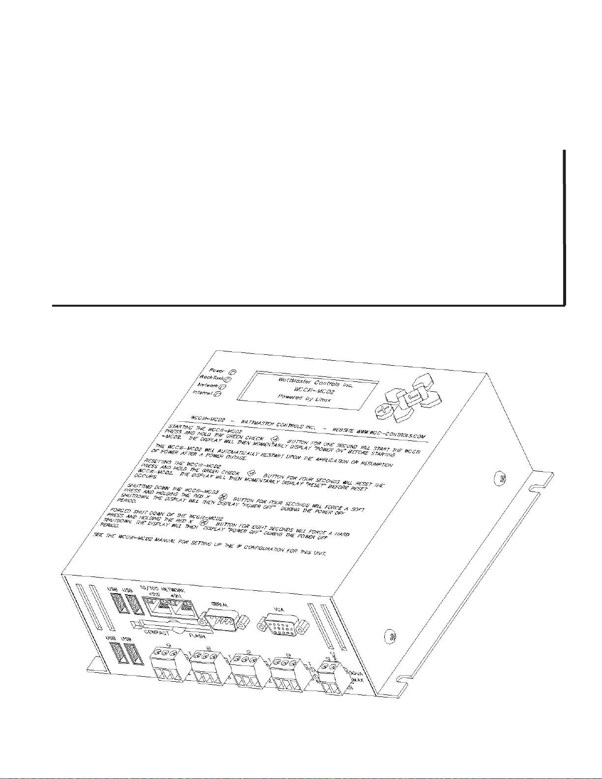
Starting the WCCIII-MCD2
Press and hold the Green Checkmark button for 1 second. The LCD
display will momentarily display, “Power On” before starting.
The WCCIII-MCD2 will automatically restart upon the application
or resumption of power after a power outage.
Resetting the WCCIII-MCD2
Press and hold the Green Checkmark button for 4 seconds. The
LCD display will momentarily display “Reset” before Reset
occurs.
Shutting Down the WCCIII-MCD2 - Soft Shut Down
Press and hold the Red X button for 4 seconds. The LCD display
will then display, “Power Of f” during the Power Of f period.
Forced Shut Down of the WCCIII-MCD2 - Hard Shut
Down
Press and hold the Red X button for 8 seconds. The LCD display
will then display, “Power Off” during the Power Off period. Files
are still open.
WCC III Technical Guide
13B-15
Page 18

13B. WCC III - MCD INSTALLATION GUIDE
WCCIII-MCD2 LCD Screens
WCCIII-MCD2 LCD Screens
System Time
The System Time Info screen displays information on the current
system time, week, day, and date. These times and dates can be
changed from the MCD-MENU (see page 25) or through the
W ebmin Access method (see page 35).
System Uptime
The System Uptime Info screen displays information on how
many days/hours/minutes since the last restart. It is often used as
a measure of computer operating system reliability and stability,
in that this time represents the time that a computer has been left
unattended without crashing or needing to be rebooted for any
administrative or maintenance purposes. This System Uptime
Info screen also displays the Backtask program running status
either as “ON” or “OFF”. Normal Status should be “ON”. The
“BACKTASK” LED should also be “GREEN” for “ON” and
“RED” for “OFF”.
CPU Load
The CPU Load Info screen displays the Total CPU load as a
percentage (17.4%), the WCCIII User CPU load (6.5%), and
the System CPU load (for the Linux Operating system), the total
system Idle time percentage (82.6%), and a 0-100% Bar Graph.
WCCIII User CPU Load: Percentage of the WCCIII-MCD2
CPU’s utilization that occurred while executing at the user level
(application). BackT ask/opt/Backtask/backtask is an application.
System CPU Load: Percentage of the WCCIII-MCD2 CPU’s
utilization that occurred while executing at the system level
(kernel). The Linux operating system is system level.
Idle Time: Percentage of the WCCIII-MCD2 CPU’s time that the
CPU was idle and the system did not do an outstanding disk I/O
request.
A computer processor is described as idle when it is not being
used by any program. Programs which make little use of the CPU
Idle Time mean that they run at a low priority so as not to impact
programs that run at normal priority like BackTask.exe. Many
programs that use the WCCIII-MCD2 CPU idle time can cause
the WCCIII-MCD2 CPU to always be 100% utilized, so that the
time spent when the WCCIII-MCD2 CPU would have been idle
is instead spent performing useful computations. This generally
causes the WCCIII-MCD2 CPU to consume more power as most
modern computer’s CPUs can enter power-save modes when they
are idle.
13B-16
WCC III Technical Guide
Page 19

13B. WCC III - MCD2 INSTALLATION GUIDE
WCCIII-MCD2 LCD Screens
NET Load
The NET Load info screen displays a real time Ethernet data
packet transmit and receive status in the fi rst column under total
KB/s and a total of Ethernet data packets transmitted and received
under the MB column.
An IP packet is the formatted unit of data that is carried by a
packet mode computer network. When the data is formatted into
IP packets, the bit rate of the communication medium (Ethernet)
can better be shared among users than if the network were circuit
switched.
Rx: Displays the number of IP Packets that are currently being
received on the network card right now.
Tx: Displays the number of IP Packets that are currently being
transmitted on the network card right now.
IP Address
The IP Address info screen displays the current Ethernet IP Address
of the network card labeled eth0. IP precedes the IP Address, NM
proceeds the Network Mask, and GW is the Gateway or Router
address to send IP packets outside of the local network. These IP
address confi gurations can be changed from the MCD-MENU (see
page 24).
The LED Labeled “Network” is a bi-color LED. When this
“NETWORK” LED is “RED” this means that there is no IP
connectivity. When the “NETWORK” LED is “YELLOW”
this means that access to the local intranet is made. When the
“NETWORK” LED is “GREEN” this means that there is a valid
connection to the Internet.
WCC III Technical Guide
13B-17
Page 20

13B. WCC III - MCD INSTALLATION GUIDE
BIOS Information For WCCIII-MC2 System Setup
13B-18
WCC III Technical Guide
Page 21

13B. WCC III - MCD2 INSTALLATION GUIDE
BIOS Information For WCCIII-MC2 System Setup
BIOS Confi guration for the
WCCIII–MCD2
The required setup information for the BIOS confi guration for the
WCCIII–MCD2 must match all of the WCCIII-MCD2 Operating
System Versions.
The initial software version of the WCCIII-MCD2 operating
system software was and is installed using a USB memory stick.
It is highly recommended that the WCC3 data be backed up
before attempting any WCCIII-MCD2 operating system reload or
upgrade. Using the initial install completely “wipes out” and in
other words “erases” all of this WCC3 data information.
Warning: The jumper labeled “J2” on the MCOMM board
(WM part # PL1 024 16-AT) should be removed during initial
software loading, but every effort must be used to ensure that
this jumper is put back “ON” after the software have been
loaded.
Linux Ubuntu Version 12.04 LTS (Long Term Support) for the
operating system will end on April 2017 for the WCCIII-MCD2.
Sometime before that date, WattMaster Controls, Inc. will force
an upgrade of the Linux Ubuntu operating system software for the
WCCIII-MCD2 to a more current supported version.
Linux Operating System Software
Installation Procedure for the
WCCIII-MCD2
Plug the VGA monitor and USB type keyboard into the WCCIIIMCD2. Then insert the USB memory stick that is preloaded with
the required WCCIII-MCD2 installation software (WM part
# SS50??) into one of the four bottom USB connectors that are
located on the bottom connector side of the WCCIII-MCD.
Warning: The jumper labeled “J2” on the MCOMM board
(WM part # PL1 024 16-AT) should be removed during initial
software loading, but put back “ON” after the software have
been loaded.
Once you have loaded the software successfully, press the “Delete”
or “Del” key on the USB style keyboard. This will cause the
WCCIII-MCD2 single board computer to go in to the BIOS setup
screens. The corresponding BIOS setup screen information must
exactly match what is printed here in this document. Then this
information must be saved by using the action command of Exit
and Save. See pages X for the installation screens.
WCCIII-MCD2 On/Off/Shut Down/Reset
Buttons
Starting the WCCIII-MCD2
Press and hold the Green Checkmark button for 1 second. The LCD
display will momentarily display, “Power On” before starting.
The WCCIII-MCD2 will automatically restart upon the application
or resumption of power after a power outage.
Resetting the WCCIII-MCD2
Press and hold the Green Checkmark button for 4 seconds. The
LCD display will momentarily display “Reset” before Reset
occurs.
Shutting Down the WCCIII-MCD2 - Soft Shut Down
Press and hold the Red X button for 4 seconds. The LCD display
will then display, “Power Of f” during the Power Of f period.
Forced Shut Down of the WCCIII-MCD2 - Hard Shut
Down
Press and hold the Red X button for 8 seconds. The LCD display
will then display, “Power Off” during the Power Off period. Files
are still open.
WCC III Technical Guide
13B-19
Page 22

13B. WCC III - MCD INSTALLATION GUIDE
Cov er Removal of the WCCIII-MCD2
13B-20
WCC III Technical Guide
Page 23

13B. WCC III - MCD2 INSTALLATION GUIDE
Functions of the WCCIII-MCD2
WCCIII-MCD2 Functions
The main function of the WCCIII-MCD2 is to provide a hardware
and software platform for a program that WattMaster Controls
has developed called “backtask”. The BACKTASK program is so
named because it is a multiple BACKground T ASKing application
program.
The BACKT ASK program does a lot of various functions such as:
USB communications to the internal MCOMM board, Time clock
functions, analog/binary global processing, overrides of control
points, Holiday scheduling, Optimal starts, PID programs, Shed /
Restore programs, Duty cycle programs, Proportional Programs,
Tenant Overrides, and Emailing of alarms. The BACKTASK
program also provides for remote IP connection to a set of
Windows-based programs generally referred to as the WCC III
programs.
If the BACKT ASK program is not running on the WCCIII-MCD2,
there is a watchdog circuit on the WCC3 MCOMM board that will
automatically restart/reset the WCCIII-MCD2 within 3 minutes.
This watchdog circuit may interfere with the installation of new
BACKTASK software. There is a way to disable this watchdog
circuit. Please contact WattMaster Controls for further important
information on temporally disabling this watchdog circuit. A two
pin berg jumper that is labeled “SBC RESET” on the WCC3
MCOMM board enables (ON) or disables (OFF) this watchdog
circuit, but this jumper must be “ON” for normal operation, and
if this “SBC RESET” jumper is left “OFF” then the automatic
restart/reset function of the WCCIII-MCD2 is then inoperable, and
may cause future undesirable operating issues. Manual reset from
the CrystalFontz LCD interface is also enabled/disabled with this
jumper, too.
This WCCIII-MCD2 also has hardware (WCC3 MCOMM board)
that interfaces to four isolated RS-485 communications loops
that then connects to various SAT III type controllers for building
automation controls.
The 24VAC@50VA power transformer for the WCCIII-MCD2 is
to be connected to a dedicated APC
Power Supply) outlet so that the MCD will keep running during a
minor power outage. The Cable/DSL modem/router should also be
plugged into one of these dedicated UPS (Uninterruptible Power
Supply) outlets. Take note that the UPS may have several outlets
but not all are marked backup power. Some are sur ge suppression
only. Use the backed up power outlets.
TheWCCIII-MCD2 has the ability to monitor power status of
the UPS to control the shutdown of the WCCIII-MCD2 via the
supplied APC USB cable. These commands that are sent from an
TM
APC
brand UPS (Uninterruptible Power Supply) upon detection
of loss of power will alert the WCCIII-MCD2 of power failure
that is then logged to the MCD’s SYSLOG fi le. The MCD will
monitor the UPS until there are 3 minutes of power remaining and
then initiate a shut-down of the WCCIII-MCD2. Upon resumption
of normal power, the WCCIII-MCD2 will power up on its own and
log the event in the SYSLOG of the OS.
TM
brand UPS ( Uninterruptible
Again, great caution must be used to ensure that this “SBC RESET”
jumper on the WCC3 MCOMM board is set back to enabled (ON)
if it is ever disabled for any and all software installations that occur
in the fi eld. This enabling/disabling of the “SBC RESET” jumper
is not normally done for simple setting of the IP addressing.
WCC III Technical Guide
13B-21
Page 24

13B. WCC III - MCD INSTALLATION GUIDE
MCD-Menu Program
How to Setup the IP Address on the
WCCIII –MCD2 with the mcd-menu
Program
Obtain a VGA monitor and a USB keyboard to connect to the
WCCIII-MCD2 device. There is a standard VGA monitor 15
pin connector on the bottom of the WCCIII-MCD2 device for
connection to a VGA type monitor. There are four external USB
connectors on the bottom of the WCCIII-MCD2 device, and
you can use any one of these external USB ports for a keyboard
connection.
Prior knowledge of Linux is not required, but would be helpful.
WattMaster Controls has developed a simple setup installation
program for the Linux command line interface, and this program is
called mcd-menu. This mcd-menu program has 16 functions that
are incorporated into it that will allow for the following operations
to be performed:
1. The setup the Network IP Confi guration of the WCCIII-
MCD2 network card interface.
2. The setup of the MCD’s Time Zone.
3. Copying of the BackT ask specifi c data fi les to the root
of the USB Drive.
4. Restoring of the BackT ask specifi c data fi les from the
root of the USB Drive.
5. The testing of APC Smart UPS connection via USB.
6. The restart of the APC Monitor server software.
7. The testing of the Internet Connection, from the
WCCIII-MCD2 to the Internet.
8. The testing of DNS Settings, from the WCCIII-MCD2
to the Internet.
9. Updating the WCCIII-MCD2 via USB Drive.
10. Updating the WCCIII-MCD2 via the Internet.
11. The resetting of the WCCIII-MCD2 IP address back to
the WattMaster factory Default IP Address settings.
12. The resetting of the WCCIII-MCD2 DNS settings back
to the WattMaster factory default DNS settings.
13. The restarting of the 4 by 20 line LCD Driver that is
located on the front of the WCCIII-MCD2.
14. The restarting of the 4 by 20 line LCD Display that is
located on the front of the WCCIII-MCD2.
15. The shutdown of the WCCIII-MCD2 – properly closing
down.
16. The shutdown and reboot of the WCCIII-MCD2.
The Webmin access method can also accomplish some of these
same tasks, but is a little bit harder to use and is meant to be more
of an “off-site” management tool for the WCCIII-MCD2. The
mcd-menu program is meant to be used as the initial IP setting,
time zone setting, and BACKTASK data fi le loading tool for the
WCCIII-MCD2. For this, a monitor and keyboard needs to be
connected temporally just for the initial IP setup and BACKTASK
data fi le loading.
The default administration username is wcciii and the password is
wt@@58.
This username and password are both CASE sensitive, and should
be entered in lower case letters only.
The administration username will time out after 15 minutes, and
you will be required to reenter the user name, and password again.
Type “mcd-menu” at the at the wcciii@wcciii-mcd:~$ prompt
(which is view only – restricted access). You can do very few
functions in View only restricted access, such as, copy/restore
WCCIII data fi les, check the IP Address, and check the UPS status.
Type “sudo mcd-menu” at the wcciii@wcciii-mcd:~$ prompt to
perform root level tasks like confi gure the IP address, shutdown the
WCC III - MCD, reboot the WCC III - MCD, reset the WCC III –
MCD IP addresses and DNS settings to DEF AULT confi gurations,
set time zones, restart the APC Monitor server, run updates from
USB or Internet, and copy/restore WCCIII data fi les.
Caution must be exercised with the sudo (super user) command
because it can render your WCCIII-MCD2 system unable to
communicate with the outside world if improperly used.
If you have selected a command requiring sudo (Super User)
access, the program will give you a warning message as listed
below:
****************************************************
* *
*
Warning: The program is not running as root. *
* Interface configurations or saving may fail! *
*
*
******************************************
13B-22
WCC III Technical Guide
Page 25

13B. WCC III - MCD2 INSTALLATION GUIDE
MCD-Menu Program
The mcd-menu is straight forward. You can select the desired
function by number (1 to 16) and hit the enter key to execute the
desire function. You can quit this mcd-menu program at any time
by typing “quit” and then pressing the enter key to quit. Then type
“exit” to return to the WCCIII-MCD2 Login: prompt.
Helpful hint: While at the wcciii@wcciii-mcd:~$ prompt, you
can select / toggle through previously entered commands with the
“UP” arrow key.
The new fi les are rolled into the installation fi les so they will be
available on new systems. They can also be pushed or updated
to older systems via secure ftp and then run from the shell.
Alternatively, they can also be uploaded to the WCCIII-MCD2
from inside the W ebMin program and then run from the command
line from within the browser. This mcd-menu program may be run
remotely from “Putty”, which is a terminal emulator application
program, provided that this program is installed and properly setup
on your computer.
NOTE: DO NOT run the mcd-menu program from inside
Web Min’ s Command Shell. It will not work there. This mcdmenu program is meant to work only from telnet/ssh session or
from the actual console (i. e. US B keyboard and VGA monitor that
is directly connected to the WCCIII-MCD2 ).
Press ENTER (or “d”) to scroll downward
OR “u” to scroll upward (T ype “quit” to quit)
PLEASE ENTER A CHOICE: ___
Helpful hint: You do not have to use the “u” or “d” keys and then
the “enter” to toggle between the fi rst and second menus. By using
just the “enter” key, you can toggle between the fi rst menu screen
with selections of 1 to 10 and the second menu screen that has
selection 11 only.
Please Pick a Function:
11. Reset MCD to Default IP Address
12. Reset MCD to Default DNS Settings
13. Restart LCD Driver
14. Restart LCD Display
15. Shutdown MCD
16. Shutdown and Reboot MCD
16 T otal Choices
Press ENTER (or “d”) to scroll downward
OR “u” to scroll upward (T ype “quit” to quit)
Using the default low level username wcciii and password
wt@@58, type mcd-menu at the prompt (view only – restricted
access)
Type sudo mcd-menu at the prompt (unrestricted access) (maybe
required to re-enter the password again).
The following fi rst main menu screen should appear:
Please Pick a Function:
1. Setup Network Confi guration
2. Setup Time Zone
3. Copy BackT ask Files to USB Drive
4. Restore BackT ask Files from USB Drive
5. T est APC UPS Connection
6. Restart APC Monitor Server
7. T est Internet Connection
8. T est DNS Settings
9. Update MCD2 via USB
10. Update MCD2 via NET
16 T otal Choices
PLEASE ENTER A CHOICE: ___
Helpful hint: You do not have to use the “u” or “d” keys and then
the “enter” to toggle between the fi rst and second menus. By using
just the “enter” key, you can toggle between the fi rst menu screen
with selections of 1 to 10 and the second menu screen that has
selection 11 only.
WCC III Technical Guide
13B-23
Page 26

13B. WCC III - MCD INSTALLATION GUIDE
MCD-Menu Program
Setup Network Configuration
(Choice #1)
This sub program will allow you to set the IP confi guration of the
WCCIII-MCD2. You will be prompted to enter an IP Address in
the XXX.XXX.XXX.XXX format. If you do not have all of the
following information, then you should not proceed any further.
Fill in the blanks below for future reference.
Static IP address __ __ __ . __ __ __ . __ __ __ . __ __ __
Subnet Mask __ __ __ . __ __ __ . __ __ __ . __ __ __
Gateway __ __ __ . __ __ __ . __ __ __ . __ __ __
Nameserver __ __ __ . __ __ __ . __ __ __ . __ __ __
Nameserver __ __ __ . __ __ __ . __ __ __ . __ __ __ Optional
Nameserver __ __ __ . __ __ __ . __ __ __ . __ __ __ Optional
Y ou will be now be prompted to enter the following data, and if you
do not want to change the address listed within the listed brackets
[ ] then just press the enter key and the value in the brackets [ ]
will not change.
Enter interface confi guration data:
Interface to confi gure: [eth0] __
IP address: [192.168.100.101] __
Netmask: [255.255.255.0] __
Gateway (none for no gateway): [192.168.100.1] __
Nameservers (blank separate list): [8.8.8.8 8.8.4.4] __
Interface to confi gure: [eth0] __ There are two possible entries
here “eth0” and “eth1”
Some internet service providers do not have a static IP address.
They use what is called static host names, which correspond to an
actual static IP address. You can enter more than one IP address
here, a primary and a secondary, And please note that they must be
separated by a space.
For example, on the Internet, there exists a special case of
nameservers lookup sites, the so-called Domain Name System
(DNS) servers, which are used to translate a static hostname or
a domain name (for example, ‘WCC-CONTROLS.com’) to its
corresponding binary identifi er (the IP address 50.87.183.62), or
vice versa..
After you have entered in all of the required IP addresses, subnet
masks, Gateways, and or Nameservers, the program will now
change the internal IP network confi guration fi les within the Linux
operating system of the WCC III – MCD. It will take a few seconds
to do this function, and the following messages will display:
Confi guring interface:
/sbin/ifconfi g eth0 24.123.103.99 netmask 255.255.255.248
broadcast 24.123.103.103
Deleting old interface route:
/sbin/route del -net 24.123.103.96 netmask 255.255.255.248 eth0
Setting interface route:
/sbin/route add -net 24.123.103.96 netmask 255.255.255.248 eth0
Deleting old default route:
/sbin/route del default
Setting default route:
/sbin/route add default gw 24.123.103.97
Writing /etc/network/interfaces:
Writing /etc/resolv.conf:
eth0 is the default main IP address for the WCCIII-MCD2.
Eth1 is the secondary IP address for the WCCIII-MCD2 and it is
meant for direct connection from the WCCIII-MCD2 to a local
computer (Laptop) via an Ethernet crossover cable. Note: Do not
change this “eth1” IP address.
IP address: [24.123.103.99] __. This IP address must be supplied
by your Internet provider or by your network IT personnel. This IP
address must be a “static IP address” (fi xed), as in not dynamic –
which does change.
Netmask: [255.255.255.248] __. This IP address must be supplied
by your Internet provider or by your network IT personnel.
Gateway (none for no gateway): [24.123.103.97] __. This IP
address must be supplied by your Internet provider or by your
network IT personnel.
Nameservers (blank separate list): [8.8.8.8 8.8.4.4] __ . Is the
actual IP address for a DNS server.
13B-24
When completed the following information will be displayed:
New netstat settings:
24.123.103.96 0.0.0.0 255.255.255.248 U 0 0 0 eth0
192.168.200.0 0.0.0.0 255.255.255.0 U 0 0 0 eth0
0.0.0.0 24.123.103.97 0.0.0.0 UG 0 0 0 eth0
Network Confi guration Done.
*************************************************
* Warning: The program is not running as root. *
Interface configurations or saving may fail! *
*
******************************************
wcciii@wcciii-mcd:~$
NOTE: The mcd-menu program will close after the setup
process for the IP connections. This is done purposely and is
normal operation.
WCC III Technical Guide
Page 27

13B. WCC III - MCD2 INSTALLATION GUIDE
MCD-Menu Program
Setup Time Zone (Choice #2)
This function will call the Time Zone confi guration program
inside of Linux. The actual command is ‘sudo dpkg-reconfi gure
tzdata’ followed by a ‘sudo service cron restart’. This program
will bring up a menu of locations to set a time zone to. Not all
cities and localities will be listed, so select one from your time
zone. For ease of selections, US is listed towards the bottom of the
list and time zones are listed in a sub-menu as Eastern, Central,
Mountain, and Pacifi c.
Select US or Geographical Area and hit the Enter key.
Select the Time and hit the Enter key.
WCC III Technical Guide
13B-25
Page 28

13B. WCC III - MCD INSTALLATION GUIDE
MCD-Menu Program
Copy the Backtask Data Files to USB
Drive (Choice #3)
This sub-program will copy all of the useful WCC III data fi les to
a USB drive (User / Contractor provided), assuming that there is
a USB drive plugged into any of the USB ports on the WCCIIIMCD2. It will copy all of these fi les to the root of the USB drive.
This program assumes there is a USB fl ash drive inserted in the
bottom of the WCCIII-MCD2 even if it is not there. Therefore,
the program will not report that there is a drive reading or writing
error or any other errors. So when backing up the Backtask data
fi le, make sure that there is a USB fl ash drive in one of the USB
ports on the bottom of the WCCIII-MCD2. The LED on the USB
fl ash drive should light up when any data is written or read from
it. Please verify that this LED operates when backing up backtask
data to this USB fl ash drive.
All WCC III jobsites have multiple specifi c custom data fi les that
are the responsibility of the end user and/or mechanical contractor.
Any loss or the actual retention of these jobsite specifi c custom
data fi les are not within W attMaster Controls, Inc. liabilities.
The following will be displayed on the screen:
Selecting Copy Backtask Files to USB Drive.
Copying fi le: /opt/backtask/AlarmBits.dat
Copying fi le: /opt/backtask/AlarmMessage.dat
Copying fi le: /opt/backtask/EnergyConsumption.dat
Copying fi le: /opt/backtask/GeneralMessage.dat
Copying fi le: /opt/backtask/GlobalAnalog.dat
Copying fi le: /opt/backtask/GlobalBinary.dat
Copying fi le: /opt/backtask/HolidaySchedule.dat
Copying fi le: /opt/backtask/LookUpTable.dat
Copying fi le: /opt/backtask/Backtask/NetworkInformation.dat
Copying fi le: /opt/backtask/Backtask/OperatorCode.dat
Copying fi le: /opt/backtask/Backtask/OptimalSchedule.dat
Copying fi le: /opt/backtask/Backtask/OverrideSchedule.dat
Copying fi le: /opt/backtask/Backtask/PidProgram.dat
Copying fi le: /opt/backtask/Backtask/ProportionalReset.dat
Copying fi le: /opt/backtask/Backtask/ShedRestoreSchedule.dat
Copying fi le: /opt/backtask/Backtask/StatusMessage.dat
Copying fi le: /opt/backtask/Backtask/SystemParameter.dat
Copying fi le: /opt/backtask/Backtask/table.dat
Copying fi le: /opt/backtask/TenantEvent_001_2009_09.dat
Copying fi le: /opt/backtask/TenantEvent_004_2009_10.dat
Copying fi le: /opt/backtask/TenantOverride.dat
Copying fi le: /opt/backtask/TenantOverrideRecord.dat
Copying fi le: /opt/backtask/UnitMessage.dat
Copying fi le: /opt/backtask/WeekSchedule.dat
Done copying .dat fi les.
Copying SlideFiles.
Done copying SlideFiles.
Copying WGGC fi les.
Done copying WGGC fi les.
Returning to Main Menu.
The screen should now take you back to the mcd-menu main
screen after about a second or two.
13B-26
WCC III Technical Guide
Page 29

13B. WCC III - MCD2 INSTALLATION GUIDE
MCD-Menu Program
Restore BackT ask da ta Files to USB
Drive (Choice #4)
This subprogram will copy all of the useful WCC III data fi les from
a USB drive (User / Contractor provided), assuming that there is
a USB drive plugged into the USB port on the WCCIII-MCD2. It
will copy all of these fi les to the /opt/Backtask subdirectory of the
WCCIII-MCD2 solid state SATA hard drive.
If there is not a USB fl ash drive in the USB port on the bottom
of the WCCIII-MCD2, this program assumes that there is a USB
drive there even if it is not there. It will not report that there is
a drive reading or writing error, or any other errors. So when
restoring data fi les, make sure that there is a USB fl ash drive in the
USB socket port on the bottom of the WCCIII-MCD2. There is
an LED on this USB fl ash drive that should light up when data is
written or read from it. Please verify that this LED operates when
restoring data from this USB fl ash drive.
All WCC III jobsites have multiple specifi c custom data fi les that
are the responsibility of the end user and or mechanical contractor.
Any loss or the retention of these jobsite specifi c custom data fi les
are not within WattMaster Controls, Inc. liabilities.
The following will be displayed on the screen:
Copying fi le: /media/usb/OverrideSchedule.dat
Copying fi le: /media/usb/PidProgram.dat
Copying fi le: /media/usb/ProportionalReset.dat
Copying fi le: /media/usb/ShedRestoreSchedule.dat
Copying fi le: /media/usb/StatusMessage.dat
Copying fi le: /media/usb/SystemParameter.dat
Copying fi le: /media/usb/table.dat
Copying fi le: /media/usb/TenantEvent_001_2009_09.dat
Copying fi le: /media/usb/TenantEvent_004_2009_10.dat
Copying fi le: /media/usb/TenantOverride.dat
Copying fi le: /media/usb/TenantOverrideRecord.dat
Copying fi le: /media/usb/UnitMessage.dat
Copying fi le: /media/usb/WeekSchedule.dat
Done copying .dat fi les.
Copying SlideFiles.
Done copying SlideFiles.
Copying WGGC fi les.
Done copying WGGC fi les.
Returning to Main Menu.
Selecting Restore BackT ask Files from USB Drive.
Restoring .dat fi les.
Copying fi le: /media/usb/AlarmBits.dat
Copying fi le: /media/usb/AlarmMessage.dat
Copying fi le: /media/usb/DutyCycleSchedule.dat
Copying fi le: /media/usb/EnergyConsumption.dat
Copying fi le: /media/usb/GeneralMessage.dat
Copying fi le: /media/usb/GlobalAnalog.dat
Copying fi le: /media/usb/GlobalBinary.dat
Copying fi le: /media/usb/HolidaySchedule.dat
Copying fi le: /media/usb/LookUpTable.dat
Copying fi le: /media/usb/NetworkInformation.dat
Copying fi le: /media/usb/OperatorCode.dat
Copying fi le: /media/usb/OptimalSchedule.dat
WCC III Technical Guide
13B-27
Page 30

13B. WCC III - MCD INSTALLATION GUIDE
MCD-Menu Program
T est APC UPS Connection (Choice #5)
This function will call the apcaccess program and display the
results in two columns. If no APC brand Smart UPS is present, a
message stating check UPS connection will appear.
*************************************************
* Check USB Cable to UPS Connection. *
*
*
******************************************
This message indicates that the UPS is not present and/or the
APCUPSD server did not start at system bootup. That would
be likely if the UPS cable was added after the installation of the
WCCIII-MCD2. Option 6 of the mcd-menu program will restart
the APC Monitor server after the connection is determined to
be true. Upon successful query of the APC UPC, the following
messages will appear:
Displaying the MCD’s UPS Monitoring Status.
APC : 001,038,1006 HITRANS : 141.0 Volts
DATE : 2013-09-26 09:47:01 -050 ALARMDEL : 30 seconds
HOSTNAME : it-cv-lx BATTV : 13.7 Volts
VERSION : 3.14.10 (13 September 20 LASTXFER : Automatic or explicit se
UPSNAME : APC NUMXFERS : 1
CABLE : USB Cable XONBATT : 2013-09-25 12:52:13 -050
DRIVER : USB UPS Driver TONBATT : 0 seconds
UPSMODE : Stand Alone CUMONBATT : 8 seconds
ST ARTTIME : 2013-09-11 13:37:00 -050 XOFFBATT : 2013-09-25 12:52:21 -050
MODEL : Back-UPS RS 700G LASTSTEST : 2013-09-25 12:52:13 -050
ST ATUS : ONLINE SELFTEST : NO
LINEV : 117.0 Volts STATFLAG : 0x07000008 Status Flag
LOADPCT : 35.0 Percent Load Capac SERIALNO : 3B1120X45754
BCHARGE : 100.0 Percent BA TTDATE : 2011-05-13
TIMELEFT : 15.9 Minutes NOMINV : 120 Volts
MBATTCHG : 5 Percent NOMBATTV : 12.0 Volts
MINTIMEL : 3 Minutes NOMPOWER : 420 Watts
MAXTIME : 0 Seconds FIRMWARE : 856.L3 .D USB FW:L3
SENSE : Medium END APC : 2013-09-26 09:47:02 -050
LOTRANS : 088.0 Volts
Followed by:
*************************************************
* UPS is online. *
*
*
******************************************
13B-28
WCC III Technical Guide
Page 31

13B. WCC III - MCD2 INSTALLATION GUIDE
MCD-Menu Program
Restart APC Monitor Server (Choice #6)
This function will call the restart the apcupsd server and attempt
to communicate with the APC via the supplied APC USB cable. If
no APC brand Smart UPS is present, the server will not start. To
check if the APC Monitor server has started, select option 5 on the
mcd-menu and test the APC UPS Connection. Important to note
here is that this software is targeted towards APC brand Smart or
Back-UPS PRO model UPS devices that connect via their supplied
USB. For example, a good model to use would be an APC BackUPS PRO 700. The MCD requires nominal power so a 700VA unit
could provide over 60 minutes of runtime if no other load was on
the same UPS.
T est Internet Connection (Choice #7)
If you have selected to Test the Internet Connection, then the
following will be displayed on the screen:
*************************************************
* Internet is on-line. *
*
*
******************************************
Selecting Test Internet Connection.
T est DNS Settings (Choice #8)
Update MCD2 via USB (Choice #9)
This function will run the Linux update program and should be
used to upgrade to any new service packs or releases. This updater
will query the USB drive for updates. These updates will be
released by WattMaster and will be available by contacting tech
support for an updated release.
Most updates will just function as installed but some will require
a restart of the MCD2 to take effect. It is also possible that some
updates will ask yes or no (Y/N) to updating the MCD2. Answer
“Y” (Yes) to these questions to permit the update process to
continue properly.
NOTE: Linux kernel updates will always require a restart.
Select Option 16 ‘Shutdown and Reboot MCD.’
Update MCD2 via NET (Choice #10)
This function will run the Linux update program and should be
used to upgrade to any new service packs or releases. This function
will only work IF the WCCIII-MCD2 is connected to the Internet.
This updater will query the Internet for WattMaster’s repositories
of updates. These updates will be released by WattMaster and will
be available for immediate release as they are published.
If you have selected to Test DNS Settings, then the following will
be displayed on the screen:
Selecting Test DNS Settings.
T esting DNS Setting in /etc/resolv.conf...
www.google.com is online.
www.yahoo.com is online.
www.wcc-controls.com is online.
DNS is resolving correctly.
The screen should now take you back to the mcd-menu main
screen after about a second or two.
Most updates will just function as installed but some will require
a restart of the MCD2 to take effect. It is also possible that some
updates will ask yes or no (Y/N) to updating the MCD2. Answer
“Y” (Yes) to these questions to permit the update process to
continue properly.
NOTE: Linux kernel updates will always require a restart.
Select Option 16 ‘Shutdown and Reboot MCD.’
WCC III Technical Guide
13B-29
Page 32

13B. WCC III - MCD INSTALLATION GUIDE
MCD-Menu Program
Reset MCD to Default IP Address
(Choice #11)
There are times when you may want to reset the IP address back to
the WattMaster Controls factory default settings.
This is primarily done at WattMaster on new systems before they
are sent out to the end user / contractor / customer. It is a base
known starting point. Please note that this will reset both of the eth0
and eth0:0 ethernet confi gurations. The following information will
be displayed on the screen:
Selecting Reset MCD to Default IP Address.
IP Address restored to Default.
IP Address Confi guration is:
# This fi le describes the network interfaces available on your system
# and how to activate them. For more information, see interfaces
(5).
# The loopback network interface
auto lo eth0 eth1
iface lo inet loopback
# The primary network interface
iface eth0 inet static
address 192.168.100.100
netmask 255.255.255.0
network 192.168.100.0
broadcast 192.168.100.255
gateway 192.168.100.1
Reset MCD to Default DNS Settings
(Choice #12)
There are times when you may want to reset the DNS settings back
to WattMaster Controls factory default settings. This is primarily
done at WattMaster on new systems before they are sent out to the
end user / contractor / customer. It is a base known starting point.
The following information will be displayed on the screen:
Selecting Reset MCD to Default DNS Settings.
DNS Settings restored to Default.
Contents of /etc/resolv.conf are:
#Google Public DNS Servers
nameserver 8.8.8.8
nameserver 8.8.4.4
The screen should now take you back to the mcd-menu main
screen after about a second or two. A Reboot is not necessary.
Restart LCD Driver (Choice #13)
On the front of the WCCIII-MCD2 there is a 4 by 20 line LCD
display. This 4 by 20 line LCD display will display the following
information:
WCCIII – MCD IP ADDRESS
WCCIII – MCD TIME AND DATE
WCCIII – MCD UPTIME
WCCIII – MCD IP RECEIVE AND TRANSMIT PACKETS
WCCIII – MCD CPU UTILIZATION
post-up iptables-restore < /etc/iptables.up.rules
# dns-* options are implemented by the resolvconf package,
if installed
iface eth1 inet static
address 192.168.200.200
netmask 255.255.255.0
broadcast 192.168.200.255
network 192.168.200.0
*************************************************
* Select Option 16 to Reboot MCD *
*
*
******************************************
...done.
The screen should now take you back to the mcd-menu main screen
after about a second or two. Select Option 16 to reboot MCD.
13B-30
This will stop the LCD driver and then restart it. The reasons why
you might want to restart the 4 by 20 line LCD driver is: There
may have been an issue with a stuck, or blanked out screen, or the
USB connection to the 4 by 20 line LCD display might have been
disconnected or locked up.
If you have selected to restart the LCD driver, then the following
will be displayed on the screen:
Selecting Restart LCD Driver.
Restarting LCD Driver...
Restarting LCDd: Stopping LCDd: LCDd.
Starting LCDd: LCDd.
The screen should now take you back to the mcd-menu main
screen after about a second or two.
WCC III Technical Guide
Page 33

13B. WCC III - MCD2 INSTALLATION GUIDE
MCD-Menu Program
Restart LCD Display (Choice #14)
On the front of the WCCIII-MCD2, there is a 4 by 20 line LCD
display. This display will display the following information:
WCCIII – MCD IP ADDRESS
WCCIII – MCD TIME AND DATE
WCCIII – MCD UPTIME
WCCIII – MCD IP RECEIVE AND TRANSMIT PACKETS
WCCIII – MCD CPU UTILIZATION
This will stop the LCD display program and then restart it. The
reasons why you might want to restart the 4 by 20 line LCD display
are: (1) there may have been an issue with a stuck or blanked out
screen, or (2) the USB connection to the 4 by 20 line LCD display
might have been disconnected or locked up.
If you have selected to restart the LCD display, the following will
be displayed on the screen:
Selecting Restart LCD Display.
Restarting LCD Display...
* Restarting backtask-lcd v1.00 display driver for MCD2
backtask-lcd [OK]
Shutdown and Reboot the MCD
(Choice #16)
This is an immediate shutdown and reboot of the WCCIII-MCD2.
You may not cancel this shutdown command with a “Ctrl” “C”
key sequence.
There are times that occur when you would need to shut down
and then restart the WCCIII-MCD2. This is generally done when
servicing the WCCIII-MCD2, or when you have software updates
to the WCCIII-MCD2.
If you have selected to shut down the MCD, the following will be
displayed on the screen:
*************************************************
* Shutdown and Reboot MCD *
*
*
******************************************
Broadcast message from wcciii@wcciii-mcd
(/dev/pts/0) at 9:01 ...11
The system is going down for reboot NOW!
The screen should now take you back to the mcd-menu main
screen after about a second or two.
Shutdown MCD (Choice #15)
There are times that occur when you would need to shut down
the WCCIII-MCD2. This is generally done when servicing
the WCCIII-MCD2 or when you have software updates to the
WCCIII-MCD2.
If you have selected to shut down the MCD2, the following will be
displayed on the screen:
*************************************************
* Shutdown MCD *
*
*
******************************************
Broadcast message from wcciii@wcciii-mcd
(/dev/pts/0) at 9:01 ...
The system is going down for halt in 3 minutes!
You may cancel this shutdown command with a “Ctrl” “C”
key sequence anytime during this 3 minute shutdown time. The
following shutdown canceled confi rming message will display:
shutdown: Shutdown canceled
WCC III Technical Guide
13B-31
Page 34

13B. WCC III - MCD INSTALLATION GUIDE
Install-Menu Program
How to Use the Initial Install and
Reco v ery Program on the WCCIII –MCD2
with the install-menu program
Obtain a VGA monitor and a USB keyboard to connect to the
WCCIII-MCD2 device. There is a standard VGA monitor 15
pin connector on the bottom of the WCCIII-MCD2 device for
connection to a VGA type monitor. There are four external USB
connectors on the bottom of the WCCIII-MCD2 device, and
you can use any one of these external USB ports for a keyboard
connection.
W attMaster Controls has developed an installation program for the
Linux command line interface, and this program is called installmenu. This install-menu program has eleven sub-programs that
will allow for the following operations to be performed:
1. The setup of a new CrystalFontz 635 Display.
2. Application of the USB over-current HOTFIX.
3. Resetting the APCUPSD server to default settings.
4. Resetting the WebMin server to default settings.
5. Resetting the internal Linux Firewall to defaults.
6. Resetting the LCD display server to default settings.
7. Creating new SSH Server keys.
8. Shutdown and Reboot MCD.
9. The install-menu program is meant to be used to
the initial IP setting tool and BACKTASK data fi le
loading tool for the WCCIII-MCD2. For this to take
place, a monitor and keyboard needs to be connected
temporarily just for the initial IP setup and BACKTASK
data fi le loading.
10. The default administration username is wcciii and the
password is wt@@58.
11. This username and password are both CAP sensitive
and should be entered in lower case letters only.
12. The administration username will time out after 15
minutes, and you will be required to reenter the user
name and password again.
13. T ype “sudo install-menu” at the wcciii@wcciii-mcd:~$
prompt to run this program. All of the selections require
root level permissions. The program menu will not run
without them.
14. NOTE: DO NOT run the install-menu program from
inside WebMin’s Command Shell. It will not work
there. This install-menu program is meant to work
only from telnet/ssh session or from the actual console
(i.e. USB keyboard and VGA monitor that is directly
connected to the WCCIII-MCD2)
The following menu screen should appear:
Please Pick a Function:
1. Setup New CrystalFontz 635 Display
2. Restore Backtask DAT Files from CompactFlash
3. Apply USB Over-Current HOTFIX and Reboot
4. Reset APCUPSD Server to Default Settings
5. Reset Webmin to Default Settings
6. Reset Firewall to Default Settings
7. Reset LCDd to Default Settings
8. Create New SSH Server Keys
9. Shutdown and Reboot MCD
16 T otal Choices
Press ENTER (or “d”) to scroll downward
OR “u” to scroll upward (T ype “quit” to quit)
PLEASE ENTER A CHOICE: ___
13B-32
WCC III Technical Guide
Page 35

13B. WCC III - MCD2 INSTALLATION GUIDE
Install-Menu Program
Setup New CrystalFontz 635 Display
(Choice #1)
This function will run the cf-yac clear and set utility that will setup
a new CF-635 lcd display.
First, the CF-635 display will clear and then populate the display
with the basic information displayed at bootup/power-on.
Then, the GPIOs built in to the CF-635 will be programmed to
display the proper LEDs and enable the POWER-ON, RESET,
and POWER-OFF sequences that are used to control the MCD2.
Finally, the settings are all saved to the CF-635’ s fl ash memory and
available for immediate use. However, a reboot of the machine and
function test of the POWER-ON, POWER-OFF, and RESET is
recommended at this time.
Restore Backtask D AT Files from
CompactFlash (Choice #2)
This function will allow the user to select the restored fi les from
the daily automatic backup that automatically occurs at midnight
every night. You can select the data restore point by month with the
most current data backup fi les being listed fi rst.
The data is stored on root, under an automatically monthly created
subdirectory system that is based on a year/month. Example:
Subdirectory that is named Dat_2013_08 is realized as August
2013. This automatic safety backup occurs at midnight every night
(The time listed for all of these fi les should be 12:00A.M.) and the
previous day’s data is over written. This continually occurs until the
last day of the month when the WCCIII-MCD will automatically
makes a new subdirectory for the new month.
Reset {APCUPSD/We bmin/Firewall/
LCDd} to Default Settings
(Choice #s { 4/5/6/7 } )
These functions will reset the various servers back to a fresh
install state. These functions should only be used if instructed by
WattMaster Controls Tech Support. These functions will replace
the fi les and permissions of their respective services and restart
those services with the new confi gurations. Any customization of
those services prior to being reset will be lost.
Create New SSH Server K eys
(Choice #8)
This function will create new SSH server keys for the Secure
Shell (SSH). These are the encryption keys that are used to enable
secure access to the MCD2 via port 22. Any connections to the
MCD2 that have previous keys will need to be cleared. Use this
function only if instructed by WattMaster Controls Tech Support.
A restart is not necessary but the only way to insure that all previous
connections are cleared.
Shutdown and Reboot the MCD
(Choice #9)
This is an immediate shutdown and reboot of the WCCIII-MCD2.
You may not cancel this shutdown command with a “Ctrl” “C”
key sequence.
There are times that occur when you would need to shut down
and then restart the WCCIII-MCD2. This is generally done when
servicing the WCCIII-MCD2 or when you have software updates
to the WCCIII-MCD2.
Apply USB Over-Current HOTFIX and
Reboot (Choice #3)
This function will modify the boot-up parameters to remedy
a known bug with a Linux kernel. The bug will cause an overcurrent on USB condition to be logged in the SYSLOG even when
one doesn’t exist. This function will initiate a system reboot after
completion.
WCC III Technical Guide
If you have selected to shut down the MCD2, the following will be
displayed on the screen:
*************************************************
* Shutdown and Reboot MCD *
*
*
******************************************
Broadcast message from wcciii@wcciii-mcd
(/dev/pts/0) at 9:01 ...11
The system is going down for reboot NOW!
13B-33
Page 36

13B. WCC III - MCD INSTALLATION GUIDE
How to Access the Linux-Based Functions
How to Access the Linux-Based
Functions of the Operating System of
the WCCIII-MCD2
Connecting to the Webmin Program is very simple and is done
by using any web browser and then accessing the Linux-based
WCCIII-MCD2 via an https webpage.
Step 1: In your web browser address fi eld, enter the following:
https://XXX.XXX.XXX.XXX:39290/
XXX.XXX.XXX.XXX = The static IP address of the WCCIII-
MCD2
The IP address should be https://192.168.100.100:39290/ (This is
the only one that the end user should change)
This is the IP address (eth0) that you should change to connect to
any network or the internet.
For a direct connection with an Ethernet crossover cable
connected between the WCCIII-MCD2 and a user computer/
laptop to confi gure the WCCIII-MCD2, the IP address should be
https://192.168.200.200:39290/
Click on “Continue to this website (not recommended)” with the
left mouse button.
You should now see:
You must now enter a valid User Name and Password.
The User Name is wcciii-admin
The Password is wt@@58
Please note that the user names and password are “CAP” sensitive.
Then click on the “Login” button with the left mouse button.
WARNING – YOU SHOULD NEVER CHANGE THIS IP
ADDRESS (eth1 Ethernet (Virtual))
Step 2: If a successful login occurs, you should now be viewing
the following screen:
13B-34
WCC III Technical Guide
Page 37

13B. WCC III - MCD2 INSTALLATION GUIDE
How to Access the Linux-Based Functions
You should now see:
You will have to click on the “MCD Controls, System, Others,
Networking, and Hardware” with the left mouse button to get to
the drop down sub-menus.
Hardware – System Time
This is to change the System/Hardware Time, the Time Zone, or to
have the MCD2 automatically synchronize the time with a remote
server.
Click on “System Time” with the left mouse button and then you
should see:
WCC III Technical Guide
13B-35
Page 38

13B. WCC III - MCD INSTALLATION GUIDE
Linux-Based Functions
Set Time
Change the Date, Month, Year, Hour, Minute, and Second to the
correct time and date for the System Time. Click “Apply” with the
left mouse button. Click “Set hardware time to system time”
Change Time Zone
Click on the “Change time zone” tab with the left mouse button.
You should now see:
Click the “Change time zone to” drop down button with the left
mouse button to see the list of time zones and then fi nd and select
the correct time zone for the MCD2’s location.
Time Server Sync
If the MCD2 is to automatically synchronize the time with a remote
server, then click on the “T ime server sync” tab with the left mouse
button and you should see:
“Timeserver hostnames or addresses” can be many different
addresses. For this example, we are using “pool.ntp.org”.
Make sure the “Set hardware time too” is selected (has a check
mark in the box). “Synchronize on schedule” should be “Yes,
at times below …” with a “Simple schedule” and “Daily (at
midnight)”.
Click “Sync and Apply” with the left mouse button.
13B-36
WCC III Technical Guide
Page 39

13B. WCC III - MCD2 INSTALLATION GUIDE
Networking – Network Confi guration
This is to change the IP address, the Gateway, and the DNS
settings using the Webmin program instead of the mcd-menu
program, although the mcd-menu program is much easier to use
and there is much less chance of making a mistake using the mcdmenu program.
Click on “Network Confi guration” with the left mouse button,
then you should see:
Network Interfaces
Click on “Network Interfaces” with the left mouse button and you
should see:
Linux-Based Functions
Click on “Activated at Boot” with the left mouse button and you
should see:
Click on “eth0”. This should be the only address that will ever be
changed.
WCC III Technical Guide
13B-37
Page 40
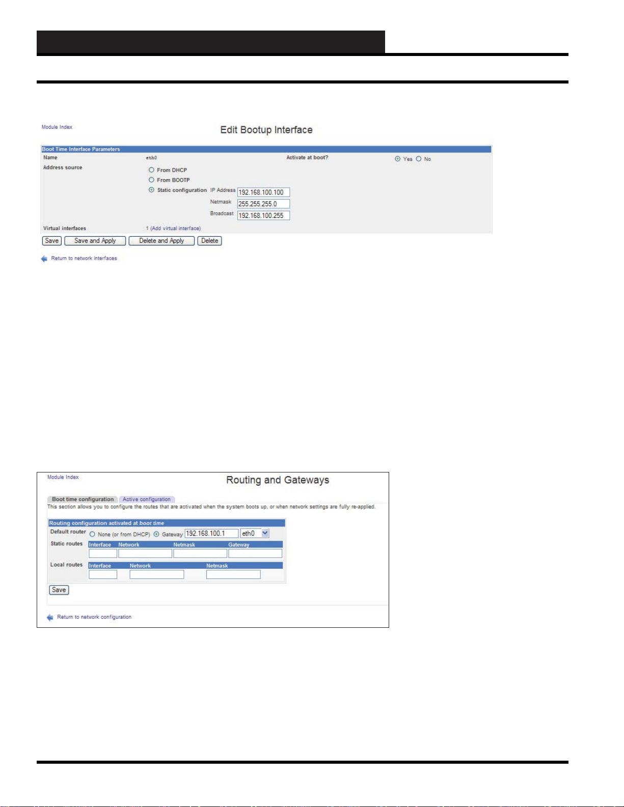
13B. WCC III - MCD INSTALLATION GUIDE
Linux-Based Functions
Now you should see:
Change the IP Address, Netmask, and Broadcast to the addresses
for the MCD2’s fi nal location.
Click “Save” with the left mouse button. (Do not click “Save and
Apply” because this will automatically change the addresses and
communication to the MCD will be lost) With just clicking “Save”
the IP addresses will not change until the MCD is rebooted. This
will take you back to the “Activated at boot” screen.
Click on “Return to network confi guration” with the left mouse
button.
Routing and Gateways
Click on “Routing and Gateways” with the left mouse button and
you should see:
Change the Gateway for the MCD2’s fi nal location.
Click “Save” with the left mouse button.
13B-38
WCC III Technical Guide
Page 41
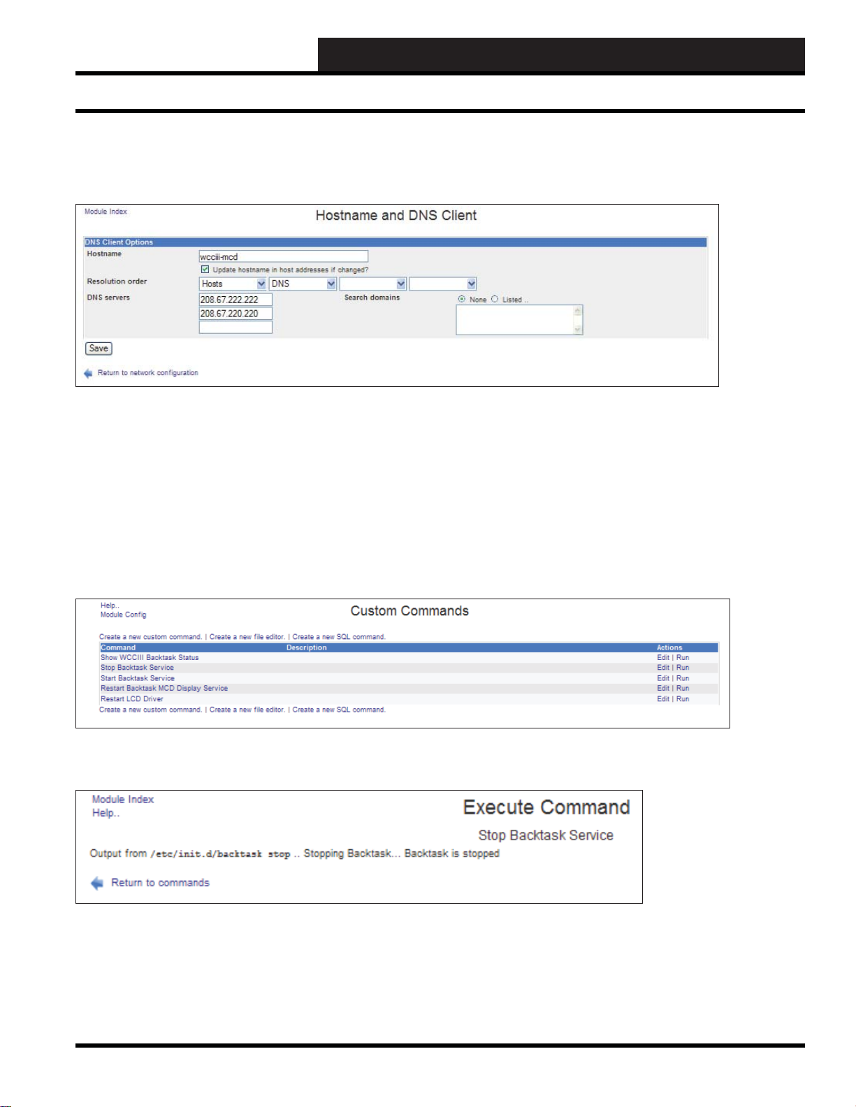
13B. WCC III - MCD2 INSTALLATION GUIDE
Hostname and DNS Client
Click on “Hostname and DNS Client” with the left mouse button
and you should see:
Change the DNS servers for the MCD2’s fi nal location.
Click “Save” with the left mouse button.
Linux-Based Functions
Now the MCD needs to be rebooted for the new IP settings to
activate.
MCD Controls – Custom Commands
T o reboot the MCD using Webmin, click on “Custom Commands”
in the “MCD Controls” sub-menu with the left mouse button. Now
you should see:
Click on “Stop Backtask Service” with the left mouse button. Now
you should see:
The MCD will automatically shut down and reboot in 2 minutes
if backtask is not running. On reboot, the new IP settings will be
in effect.
WCC III Technical Guide
13B-39
Page 42

13B. WCC III - MCD INSTALLATION GUIDE
Common Linux Commands
Common Linux Commands that would be helpful to know f or the W CCIII-MCD2
Display Current Confi g for all NIC’s: ifconfi g
Display Current Confi g for eth0: ifconfi g eth0
Display Current Confi g for eth1: ifconfi g eth1
Assign IP: ifconfi g eth0 192.168.100.100
Ping: ping -c 4 192.168.100.100
Assign second IP: ifconfi g eth1 192.168.200.200 - Used for Crossover connection
Disable network card: ifconfi g eth0 down - WARNING: Use this command only if connected through a serial port or if you have
Keyboard and Monitor hooked up.
Enable network card: ifconfi g eth0 up
Assign IP/Subnet: ifconfi g eth0 192.168.100.100 netmask 255.255.255.0
Assign Default Gateway: route add default gw 192.168.100.1
Trace Path: tracepath www.google.com - T ests if route to Internet is present
DNS Test: host www.google.com - Tests if the MCD’s DNS Settings are functioning /etc/resolv.conf
Reverse Lookup: host 209.191.93.52 - Tests reverse DNS lookup to yahoo.com
Ping XXX.XXX.XXX.XXX Pings a specifi c IP Address for testing. Under Linux it is continually testing the IP address so you
must press “Control” “C” to stop the IP pinging process.
traceroute “IP address” Provides information concerning the route which packets must take to get from your computer (the server in
this case) to a remote computer/server; typically used to diagnose possible problems in packet routing.
nslookup “IP address” Provides conversion of an IP address to an alias of a computer if it is registered in DNS (Domain Name
Service) or will provide the IP address for an alias.
sudo sudo is the superuser and as such is a privileged user who has unrestricted access to the whole system,
including all commands and all fi les regardless of their permissions. By convention, the username for the
superuser account is root.
ls (ls –al is the most useful) Lists the contents of a directory by typing on the command line. -l displays detailed information
about each fi le and directory, including permissions, owners, size and time/date when the fi le was
last modifi ed; -a option displays all the fi les and subdirectories including hidden fi les (with names
that begin with a dot); -p displays a slash at the end of each directory name to distinguish them
from fi lenames; -r displays fi les in reverse order; -t displays fi les in order of modifi cation time; -x
displays the fi lenames in columns across the screen.
chmod (permissions) fi lenames changes the permissions for a fi le; permissions should include a letter designating who gets
permissions (u for the user, g for the group, o for others, or a for all) followed by a + or - (to give or
take away the permission) followed by the kind of permission (r for read access, w for write
access, x for execute if the fi le is a program or script); the complete command that you type should
look like: chmod g-w fi lename
chown user:group fi lenames changes ownership of a fi le
13B-40
WCC III Technical Guide
Page 43

13B. WCC III - MCD2 INSTALLATION GUIDE
Common Linux Commands
passwd Changes your password
write username Sends a message to another person using the system. T o prevent someone from writing to you, see the
mesg n command.
clear Clears the screen.
ps Displays information about your processes/jobs/programs which are running on the server.
cd Change directory; cd .. moves you backwards to the next higher subdirectory level; cd / moves you to the
highest directory level.
mkdir new_directory Makes a new subdirectory with the name specifi ed by new_directory
1. cp Copy is like the rename command use as follows “cp fi lename1 fi lename2” and this leaves the old
fi le intact and makes a new copy with a new fi lename.
df Displays how much space on the disks (hard drive partitions) is free.
rm Removes or deletes fi les; the -i option asks you to confi rm that you want to delete each fi le; the -r option is
dangerous because it allow you to delete an entire directory and all of the fi les it contains.
rmdir Removes a directory; you can use the -i and -r options which are described in the rm command.
w Provides information concerning who is logged into the system and some details on how they are connected.
who Tells you who is using the server at that time.
date Displays or changes date or time in this format Day/Month/Date - Time / Time Zone / Year
Different program than under wine cmd command line interpreter .
mv Renames a fi le or moves it from one fi lename or directory to another; the -i option tells mv to prompt you
before it replaces an existing fi lename.
help Provides online help; several topics have been included in the help system available on the servers.
ifconfi g –a Ifconfi g is used to confi gure the kernel-resident network interfaces. It is used at boot time to set up interfaces
as necessary. After that, it is usually only needed when debugging or when system tuning is needed. If no
arguments are given, ifconfi g displays the status of the currently active interfaces. If a single interface
argument is given, it displays the status of the given interface only; if a single -a argument is given, it
displays the status of all interfaces, even those that are down. Otherwise, it confi gures an interface.
Command Line prompts
/ - root directory
./ - current directory
./command_name - run a command in the current directory when the current directory is not on the path
../ - parent directory
~ - home directory
$ - typical prompt when logged in as ordinary user
# - typical prompt when logged in as root or superuser
! - repeat specifi ed command
!! - repeat previous command
^^ - repeat previous command with substitution
& - run a program in background modex[T ab][Tab] - prints a list of all available completions for a command, where the beginning is
``x’ ’
WCC III Technical Guide
13B-41
Page 44

13B. WCC III - MCD INSTALLATION GUIDE
Common Linux Commands
eth0 eth0 is the network Ethernet connection #0 (Default connection) Used in conjunction with the ifconfi g command. All
changes to the Ethernet connections should only be done using the WEB_ADMIN program or the mcd-menu.pl batch
fi le. To make any changes within the Linux cmd command line interface again is very dif fi cult for the average user to
accomplish this task. Full usage commands are listed on page 46.
eth1 eth1 is the network Ethernet connection #1 (Default connection for the Ethernet connection using a crossover cable.)
On the WCCIII-MCD2 it is possible to change the IP confi guration in the Linux command line interface using the ifconfi g command, but it
is strongly recommended that any changes to the IP confi guration is done with the WEB_ADMIN interface or with the mcd-menu program
fi le. See the WEB_ADMIN WCCIII-MCD2 manual for further details.
Ifconfi g is used to confi gure the kernel-resident network interfaces. It is used at boot time to set up interfaces as necessary. After that, it is
usually only needed when debugging or when system tuning is needed.
If no arguments are given, ifconfi g displays the status of the currently active interfaces. If a single interface argument is given, it displays
the status of the given interface only; if a single -a argument is given, it displays the status of all interfaces, even those that are down.
Otherwise, it confi gures an interface.
13B-42
WCC III Technical Guide
Page 45

13B. WCC III - MCD2 INSTALLATION GUIDE
The WCC III-MCD2 Remote Serial Console
The WCC III – MCD Remote Serial
Console
Why should I be attempting this. What does this do?
Lets you log in to the WCC III-MCD2 console via a serial port
connection instead of having to attach a keyboard/monitor. From
this serial remote console, you can run mcd-menu and setup/
troubleshoot the system. Great for resetting of the ip settings and
making WCCIII-MCD2 go back to the factory defaults settings
when other methods are unavailable.
What do I need specifi cally?
Computer - A personal computer or laptop with a serial port (9
Pin) connection that is also running the windows operating system.
Y ou must have a 9 pin serial connection on this computer or laptop.
Null Modem Cable - A 9 pin Female to 9 pin Female null modem
cable. Connect this cable from the WCC III-MCD2 9 pin serial
connection in the back to your personal computer or laptop serial
connection.
WCC III Technical Guide
13B-43
Page 46

13B. WCC III - MCD INSTALLATION GUIDE
The WCC III-MCD2 Remote Serial Console
Null Modem cable
PuTT y is a free alternative to HyperTerminal and will support null
modem COM ports on Windows machines but will also allow
you to Secure Shell (ssh) into the WCCIII-MCD2. This will allow
you to operate a terminal over a network as if you were directly
connected to the MCD2 with a keyboard and monitor. Connections
made with PuTT y allow you to run the mcd-menu program, installmenu program, and any other command line instructions you may
need to run to operate or confi gure the MCD. PuTTy is available
for download at http://www.putty.org/ for free. Connections to an
MCD2 located behind a fi rewall can be confi gured through port
forwarding TCP port 22 or using a secure VPN connection to
that network. Connections to an MCD2 from inside the fi rewall
are enabled by default and no further confi guration of the MCD2
or network is required unless the Intranet has security or access
control points built into its network that would prevent ssh traffi c
from occurring.
HyperTerminal, which comes packaged with Windows95, 98,
98SE, Me, NT, 2K & XP, but is not included in Windows Vista
or in Windows 7. Windows Vista and Windows 7 do not include
HyperT erminal, although the commercial product “HyperT erminal
Private Edition” (latest version being 9.0) does support Vista and
Windows 7.0 and is available for purchase at the following website:
http://www.hilgraeve.com/
This brings up this dialog box. Enter a Name (like ‘Direct-Com-1).
Any name will do.
Chose an ICON - whatever one you wish to represent this serial
direction connection method.
When fi nished with your selection, click the “OK” button with
your left mouse button. This dialog box should then appear .
Start the HyperT erminal .exe program (hypertrm.exe). Left mouse
click on the Start button, then select the “All Programs”. Then drag
your mouse pointer up to and the select ACCESSORIES, then select
“COMMUNICATIONS”, and then select “HYPERTERMINAL”
with a left mouse click.
(Note: Some versions of Windows will have the Hyperterminal
program located directly under the “Accessories”.)
With your mouse, click the selection arrow on the “Connect using”
list box and select the COM port your (serial port) that the null
modem cable is connected to.
When you select the COM port, the phone number to dial boxes
should be now be grayed-out.
When fi nished with your selection, click the “OK” button with
your left mouse button.
13B-44
WCC III Technical Guide
Page 47

13B. WCC III - MCD2 INSTALLATION GUIDE
The COM port properties dialog box now should be displayed.
The WCC III-MCD2 Remote Serial Console
For the null modem serial connection to the WCC III-MCD2,
make sure that you set the Bits per second to “115,200”, Data bits
to “8”, Parity to “None”, Stop Bits to “1”, and Flow control to
“Hardware”.
When fi nished with your selection, click the “OK” button with
your left mouse button.
You should now be back to the main HyperTerminal window
where you should be able to control your WCC III-MCD2 from
the Linux command prompt.
Press the “Enter” key - you should now get a Linux Login prompt.
You’re ready to go!
When you end the session, make sure to say YES to save the
settings. A new icon will be created in the HyperTerminal folder
with your session-name.ht. This is a shortcut to these settings. You
can put a copy of this shortcut on your desktop for easy access, and
you will never need to repeat these setup steps.
WCC III Technical Guide
13B-45
Page 48

13B. WCC III - MCD INSTALLATION GUIDE
The WCC III-MCD2 Backup/Restore Data
WCCIII-MCD2 Backup/R estore Data to
and from USB Drives
Please see the mcd-menu program user instructions in either the
WCC3 Administrator’s Guide on pages ADMIN-3 to ADMIN-7
or the WCC III manual Section 2, Initiating the System on pages
2-20 to 2-22 for more detailed instructions on how to operate
and use the mcd-menu setup program that is located within the
WCCIII-MCD2.
The WCCIII-MCD2 provides for a backup and restore of data to
and from an end user or contractor supplied USB memory stick
from within the mcd-menu program that is run from within the
WCCIII-MCD2.
Again, the end user or contractor is responsible for this USB
memory stick data backup of the WCCIII-MCD2. The USB
memory stick should be blank before starting a backup of the
WCCIII-MCD2. The end user or contractor must verify that the
USB memory stick is blank before any attempt at backing up the
WCCIII-MCD2.
The SlideFiles subdirectory is where the necessary fi les for the
WCC3.exe program’s Custom Screens and Bitmap Screens are
backed up to and then restored from. They are normally stored
within the WCC III-MCD2 when these fi les are uploaded (Stored)
to the WCC III-MCD2 from the WCC3.exe program. This
“Upload Slide Screen Files” to the WCC III-MCD2 is a manual
user function – it is not automatically done by the WCC3.exe
program. The user must initiate this function. If there are no fi les
in this subdirectory, then there has never been any user initiated
“Upload Slide Screen Files” to the WCC III-MCD2 from the
WCC3.exe program.
The WGCCFiles subdirectory is where the necessary fi les for the
WGCC3.exe program’s Standard Graphics Screens and Custom
Graphic Screens are backed up to and then restored from. These
fi les are normally stored within the WCC III-MCD2 when these
fi les are uploaded (Stored) to the WCC III-MCD2 from the
WGCC3.exe program. This “Upload Screen Files” to the WCCIIIMCD2 is a manual user function – it is not automatically done by
the WGCC3.exe program. The user must initiate this function. If
there are no fi les in this subdirectory, then there has never been any
user initiated “Upload Screen Files” to the WCC III-MCD from
the WGCC3.exe program.
This USB memory stick data backup is unique to each and every
jobsite. We recommend that a user or contractor initiated backup
occurs every 6 months for WCCIII-MCD2 data integrity .
The directory of the standard listing of fi les on the USB memory
stick is listed above.
We store only the necessary WCC3.exe DAT fi les on this USB
memory stick - not any of the WCC3 executable programs.
The WCC3 program type of executable fi les are available from
W attMaster Controls, Inc. on an installation CDROM.
The needed Linux fi les for the initial WCC III-MCD2 build are
not generally available to the end user or contractor. They are on
a separate USB memory stick and should not be used for this USB
data backup memory stick.
There is a text fi le that is also created on this USB drive when a
backup is made to the USB drive that also lists the time and date
that this particular backup was made. This fi le is named “wcciii-
backup.txt”.
13B-46
WCC III Technical Guide
Page 49

13B. WCC III - MCD2 INSTALLATION GUIDE
Ubuntu Linux Installation
WattMaster Controls - Ubuntu Linux
Installation
NOTE: On a reinstallation of the hard drive, make sure that all
of the WCCIII-MCD2’s WCCIII data fi les have been safely
backed up to a separate USB drive or remotely backed up with
the WCC3Utilities.exe program before starting the installation
process.
Base Linux Operating System Install: Insert USB Key into your
system and press F11 to select the boot menu. Select the USB
drive and press Enter. This should bring you to a screen that looks
as follows:
On a new installation, you should select the Install WCCIII-MCD2
Release 1.0 menu option and proceed to the rest of the installation
software. This option will install all of the necessary software onto
the WCC III MCD’ s solid state hard drive.
Rescue a broken system
When selecting the Rescue a broken system, your system will be
booting in to rescue mode; the system will ask about Network and
other information. This is required to setup a rescue environment.
Now you will be prompted to select root partition or device.
Next it will try to mount root device and it will notify the same.
Now you will see a common rescue mode option such as Reinstall
GRUB or open / execute a shell etc.
Now you are in rescue mode and you need to use your own
knowledge to rescue the system. When things go wrong, there are
several ways to work on fi xing them.
A few things to remember ....
The rescue-mode CD mounts your root fi le system at /target
directory. Open or execute a shell and change the directory to /
target.
At the “Language” selection menu: Select English:
At the Main WCCIII MCD installation menu, you will have the
following options:
• Install WCCIII-MCD2 Release 1.0
• Test Memory
• Boot from fi rst hard disk
• Rescue a broken system
# ls /target
# cd /target
# mount
If you need to run a fsck command, use the fdisk -l command to
fi nd out partition name. Usually they are located at /dev/discs/
discX/partY. For example, repair 2nd partition (not mounted as /
target), you would type command:
# ls -l /dev/discs/disc0
# fsck.ext3 /dev/discs/disc0/part1
T o exit type command :
# sync ;sync
# exit
# reboot
As I said earlier in rescue mode, there is no single command that
I can recommend to fi x a problem. You need to use your own
knowledge base to rescue the system, and please don’t forget
to read the Linux command documentation before using any
command.
WCC III Technical Guide
13B-47
Page 50

13B. WCC III - MCD INSTALLATION GUIDE
Ubuntu Linux Installation
Test Memory
When selecting the Test Memory option, you should only use this
option to test the RAM and RAM I/O functions. This test will run
indefi nitely with a series of sequential and random memory read/
writes. This not only exercises the memory but also the CPU and
motherboard I/O function as it pertains to RAM. Use this test to
“burn in” the system and/or to test the reliability of the WCC IIIMCD2 board/cpu/ram components. This test will not test Serial,
Parallel, HDD, or USB controllers.
Boot from fi rst hard drive
Select the Boot from fi rst hard drive option if you are wanting to
boot from the fi rst hard drive. This is useful if you have some
additional fi les (maybe in the future) or a specifi c fi le that was
added to the USB drive after it was created.
This option is available but if you’re not booting from the USB
drive then best practice is to remove it before starting up the MCD2.
The time zone is default set to US/Central time and the drive
partitions are automatically created and installation proceeds
without further input from the user.
Now the base Linux Ubuntu operating system is being installed,
and the installation screen should be displaying the various
different fi les information in the middle of this screen. The
installation process has been automated and there should not be
any prompting for further information unless a problem occurs.
If problems occur, a restart of the process is best. Make sure that
you have both the SATA DOM and the CompactFlash installed;
otherwise, partitioning and formatting of those solid state drives
won’t be done.
The Linux operating system installation continues for 3-5 minutes
at which point other non-Linux operating system software is also
installed such as the webmin interface.
Finishing the installation: At this point, the Linux operating system
for the WCCIII-MCD2 is installed, is now creating the wcciii
user account information, and is installing the backtask program.
Other confi guration fi les that are needed for proper operation of the
WCCIII–MCD2 are also installed at this time:
Installation of the base system (Ubuntu – Linux)]
13B-48
The base Linux operating system installation is now fi nished. The
system will now reboot automatically and boot the freshly installed
OS. You may remove the USB key as soon as the system reboots.
WCC III Technical Guide
 Loading...