

Page 1

12. WCC III Installation
Guide
WCC III
12. WCC III Installation
Guide
Page 2

T ABLE OF CONTENTS
SECTION 12:
WCC III INST ALLA TION GUIDE
WCC III System Requirements .................12-1
MCD Basic Operating Conditions .............12-2
Wall Mounting of the WCC III – MCD .........12-2
WCC III – MCD Internet Access ................12-4
Sending a Text Message to a
Cell Phone via an Email from
the WCC III System ................................... 12-6
WCC III System RS-485 Communication
Wiring ........................................................12-7
WCC III - MCD Typical System
Architecture ..............................................12-8
Mounting a Satellite Controller in an
Enclosure ................................................12-10
SAT 3C Controller ..................................12-49
Addressing the SAT 3C ........................... 12-51
Addressing (Numbering) of the
TUC/RTU Controllers that are
Connected to the SAT 3C .......................12-53
SAT 3D Controller ...................................12-57
Addressing the SAT 3D ........................... 12-58
Addressing (Numbering) of the TUC
Controllers that are Connected to the
SAT 3D .....................................................12-60
SAT 3F Controller ....................................12-62
Addressing the SAT 3F ...........................12-63
Addressing (Numbering) of the TUC
Controllers that are connected to
the SAT 3F ...............................................12-65
Satellite Controllers -
General Dimensions ...............................12-15
SAT III Controller - LED Information .......12-16
SAT III Controller - Connection Points ...12-17
Addressing (Numbering) of
SAT III Controllers ..................................12-19
SAT III Relay Outputs .............................12-21
Proportional-Integral (PI) Output
Board .......................................................12-24
Binary Input with Time Delay Board ......12-27
V-Out Binary/Relay Interface Board .......12-34
SAT III Analog Inputs .............................. 12-41
TUC-2R and Four Relay Expansion
Board ......................................................12-67
TUC-2R Three Relay Expansion Board
and Damper Actuator ..............................12-68
TUC-2R Velocity Sensor ......................... 12-69
Running the WCC3 Program ...................12-70
WCC III - MCD LCD Display .....................12-73
The WCC III - MCD ...................................12-78
Using the MCD-Menu Program ...............12-79
Page 3

12. WCC III INSTALLATION
GUIDE
System Requirements
SECTION 12:
WCC III INST ALLA TION GUIDE
__________________________________________
WCC III System Requirements
To accomplish remote communications via the internet, the
following items are needed in addition to the WCC III system in
order to control the building mechanical systems. The WCC III
system is not to be used in any application where Fire/Life/Safety
is an issue.
WCC III – MCD System Requirements
(On-Site WCC III – MCD Computer):
• DSL, or a Cable router/switch that connects to the
internet. Or, as an alternative, an internal jobsite
IP network that does not connect to the internet,
but when using this internal jobsite IP network, the
external internet Email of alarms from the WCC III
- MCD will not be possible. Also, external access
via the internet may not be possible.
• A fi xed static IP address or a fi xed IP domain host
name.
• Enabled port forwarding on the Firewall of the
router/switch. This is only if a fi rewall is used.
• On earlier versions, antivirus software is initially
provided by WattMaster Controls, with Norton
antivirus software for a period of 1 year. The
customer must maintain the antivirus software after
this 1-year period. Later versions are shipped with
Linux as the operating system and do not require
anti-virus software.
• An Email address that supports a SMTP
server for SENDING with a pop server for
RECEIVING Emails, and it must have “auth
login” authentication. TLS or SSL modes are not
supported. WattMaster Controls can provide an
Email address with these requirements.
• An Uninterruptible Power Supply (UPS) – 750-
Watt minimum
• A wall mounting surface is preferred.
• A dedicated 120VAC power circuit is required.
Front End Software Requirements
(Operator Console Software):
• A Microsoft Windows XP /Vista/Windows 7-based
computer.
• Minimum hardware specifi cation for the Microsoft
Windows XP / Vista based computer is a Pentium
IV running at 2.4 Giga Hertz with at least 1 GB
of RAM, and 10 GB of spare hard drive space. A
CDROM/DVD player is also required for software
installation.
• WCC III software package – Provided on a
CDROM, or is available via a download on the
WCC Controls website: www.wcc-controls.com.
The installation CDROM contains the following
programs:
WCC III.EXE (SS5021)
WCCUTILITY.EXE (SS5023)
SCUSCR.EXE (SS5026)
WCC3Trendlog.EXE (SS5028)
TenantReport.EXE (SS5025)
TenantOverride.EXE* (SS5024)
WGCC3.EXE (SS5029)
WCC3 Download (SS5030)
WCC3 Guest (SS5022)
• The CDROM part number (WattMaster Part #
DM1WC011-01X, were “X” = revision level)
• A DSL or Cable router/switch that connects to the
internet, or access to the internet via some other
method. Or, as an alternative, an internal jobsite
IP network that does not connect to the internet,
but when using this internal jobsite IP network, the
external internet Email of alarms from the WCC III
- MCD may not be possible.
* NOTE: The TenantOverride.exe program is also available
as a single program installation for the end users that are using
the simplistic graphical interface of the TenantOverride.exe
screen to locally turn on and off specifi c control points that are
applicable to the end user.
WCC III Technical Guide
12-1
Page 4
12. WCC III INSTALLATION
Basic Operating Conditions and Wall Mounting
The WCC III – MCD Basic Operating
Conditions
The WCC III - MCD must be kept in a clean and dry area in the
building. The ambient temperature must be between 50 and 100 °F,
and the relative humidity must be kept between 0 and 90% (noncondensing). The interior components are cooled by ventilation
fans within the WCC III – MCD unit, and therefore the unit should
not be kept in tightly confi ned or enclosed areas. The WCC III -
MCD is primarily designed to mount on a wall with the supplied
brackets.
The WCC III – MCD computer requires 115 VAC power and must
remain powered at all times for proper operation and control. The
115 VAC power circuit must be separate and dedicated exclusively
to the WCC III – MCD computer.
The WCC III - MCD system is designed to automatically restart
after a power failure. However, the industrial computer which
acts as the WCC III Master Communications Device will not
automatically reboot unless the power is shut off cleanly and
then restored cleanly. During most power outages, the incoming
115 AC voltage could have great fl uctuations before the power
fi nally fails. In a like manner, brownouts will usually cause the
industrial computer to “lock-up.” That is to say, the screen will
continue to display on the monitor, but the cursor will not respond
to the keyboard commands. To prevent this “lock-up” issue from
happening to the WCC III – MCD, an Uninterruptible Power
Supply (UPS) is required on each and every WCC III – MCD
computer.
An Uninterruptible Power Supply (UPS) provides emergency
power to keep the WCC III Master Communications Device
(personal computer) on-line for several minutes after a primary
power failure. The UPS regulates the incoming power to the
computer and shuts the power off cleanly several seconds after the
power outage, or brownout. When the primary power is restored,
the UPS brings the MCD back on-line automatically. The WCC
III system does not lose any information since all of the programs
and user entered data are stored on either a disk in the MCD, on
fi rmware, or on battery backed memory in the satellite controllers.
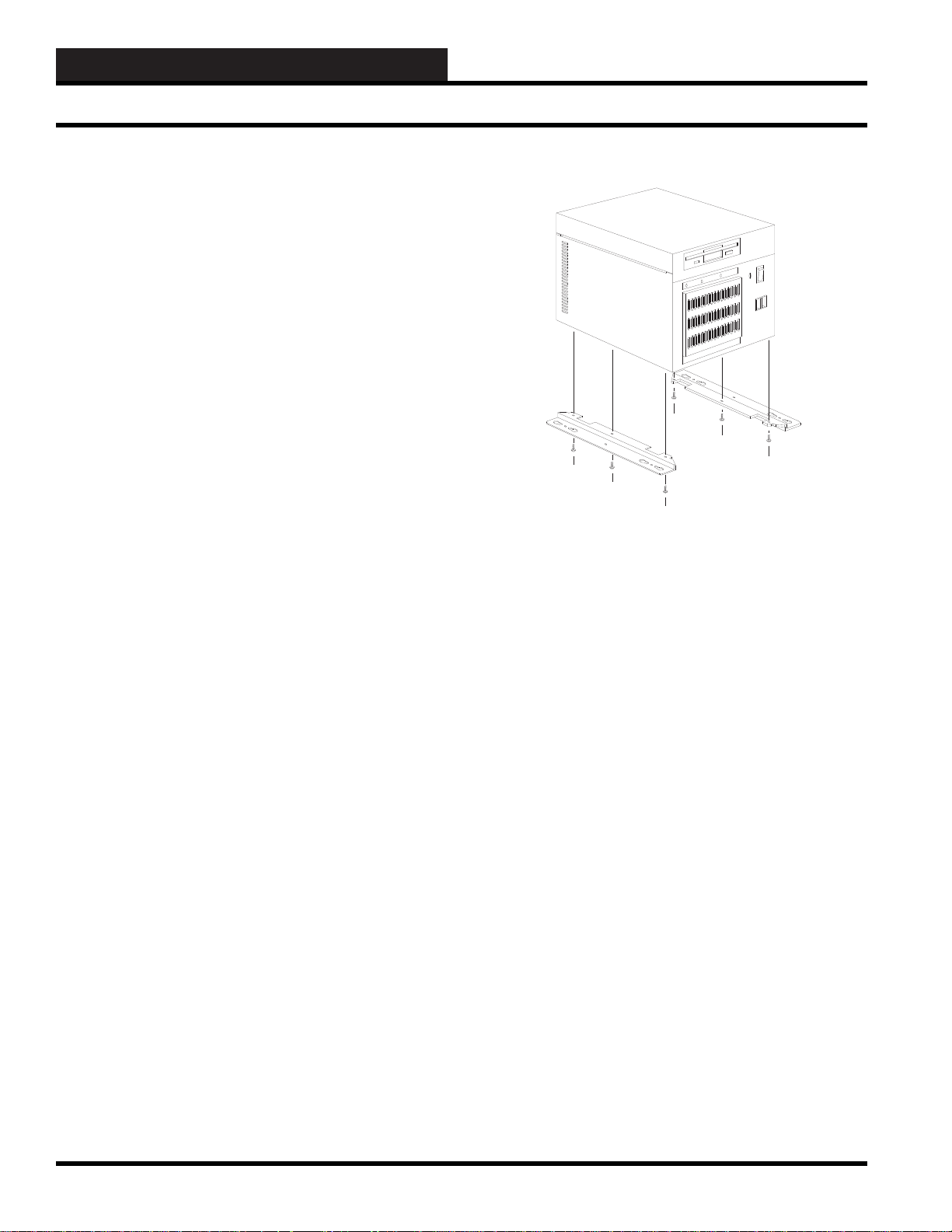
Figure 12-1: Installing the six screws for the two wall
mounting brackets of the WCC III – MCD Computer
Do not mount the WCC III – MCD computer straight into the
drywall. The use of a ¾-inch plywood “Backer Plate Board” is
required. You may want to paint this plywood “Backer Plate
Board” to match the color of the wall before mounting to the wall.
See Figure 12-2 for further application.
Backer Plate Mounting Notes:
Use correct type of wall mounting anchors for mounting on a
concrete wall for the mounting of the “Backer Plate Board” if and
when mounting the Backer Plate Board to a concrete wall. Use
at least 2-inch dry wall type screws if mounting the Backer Plate
Board to a “Dry-Wall” type wall. Mount the “Backer Plate Board”
so that the screws that are holding the “Backer Plate Board” are on
the 16-inch centers of the wall studs where applicable.
Mount the WCC III - MCD 4-½ to 5-½ feet off of the ground on a
suitable wall, in an air conditioned space. This area should not have
any radio transmitting or telephone switching gear in the space, or
near the space, or located on the back side of the adjacent wall.
Wall Mounting of the WCC III – MCD
It is strongly suggested that the WCC III – MCD is mounted on the
wall. General guidelines are as follows:
Always install the supplied six screws for the two supplied wall
mounting brackets for the WCC III – MCD Computer as shown in
Figure 12-1. Be sure to tighten the six screws so that they do not
loosen over time.
12-2
Do not block the airfl ow vents that are coming out of the WCC III-
MCD. Do not apply paint to the WCC III-MCD enclosure. Do not
cover the WCC III-MCD with any protective plastic while painting
with the WCC III-MCD turned on. The UPS battery backup unit
should be located within 3 or 4 feet of this WCC III – MCD.
WCC III Technical Guide
Page 5
12. WCC III INSTALLATION
Wall Mounting of the WCC III - MCD
Wall Mounting of the WCC III - MCD
Front view with wall mounting brackets
GUIDE
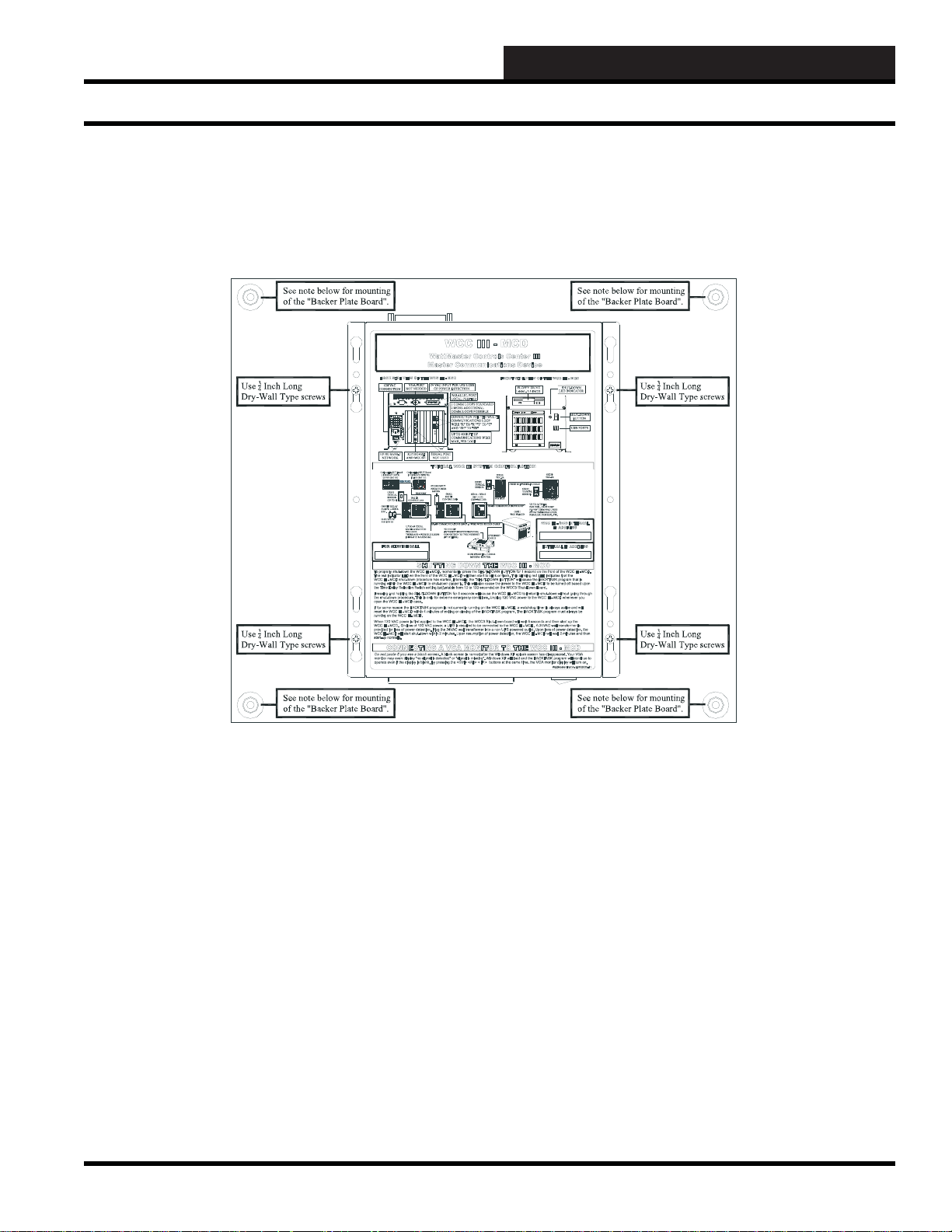
Use 3/4 inch plywood for the backer plate board
(supplied by others)
Figure 12-2: Wall mounting instructions for the WCC III – MCD
NOTES:
at least 2-inch dry wall type screws. Mount the backer plate board so that the screws that are holding the backer plate board are on the 16inch centers of the wall where applicable.
Mount the WCC III - MCD 4-½ to 5-½ feet off of the ground on a suitable wall in an air conditioned space. This space should not have any
radio transmitting or telephone switching gear in the space, or near the space, or located on the back-side of the adjacent wall.
Do not block the airfl ow vents that are coming out of the WCC III - MCD. Do not apply paint to the WCC III - MCD enclosure. Do not
cover the WCC III - MCD with any protective plastic while painting with the WCC III - MCD turned on.
The UPS should be located within 3 or 4 feet of this WCC III - MCD.
WCC III Technical Guide
Use approved anchors when mounting backer plate board on a concrete wall. If mounting backer plate board to dry wall, use
12-3
Page 6

12. WCC III INSTALLATION
WCC III - MCD Internet Access
WCC III – MCD Internet Access
The most common question asked is: Why does the WCC III –
MCD computer need to have Internet access?
If WattMaster Controls factory assistance or troubleshooting is
required for a WCC III system, a representative from the factory
can access the system with a remote computer and view the same
WCC III Screens as the end user or contractor in the building. This
allows the end user or the contractor for the building installation to
talk to the factory representative while they are both viewing the
same screens.
The Emailing of important alarm notifi cations for up to 60 Email
Addresses is provided for from the WCC III – MCD.
The ability to send alarm notifi cation via a text message to a
cellular phone.
Secure Remote communications package (WCC III software) is
provided for FREE. A CD-ROM is supplied for installation.
World-wide, multiple remote connections (up to 255 simultaneous
connections possible)
On earlier versions, antivirus software is initially provided by
WattMaster Controls, with Norton antivirus software for a period
of 1 year. The customer must maintain the antivirus software after
this 1-year period. Later versions are shipped with Linux as the
operating system and do not require anti-virus software.
The ability for internet based tenant override requires internet
access.
WCC III – MCD Cable Modem/Router
T echnical Considerations
The WCC III-MCD uses internet access to e-mail alarms and to
provide remote IP access for multiple remote WCC III operator
programs.
The DSL / Cable modem USB connection should not be connected
to any of the USB ports on the WCC III – MCD. The DSL / Cable
modem Ethernet connection should only be connected to the
Ethernet port on the WCC III – MCD if the DSL / Cable modem
has a built-in internal router with Ethernet switch.
The use of a DSL / Cable modem with an external router that is
then connected to the WCC III - MCD is also a recommended way
to connect the internet to the WCC III – MCD. The use of only a
plain DSL / Cable modem without an internal router with a built-in
switch is not currently recommended by WattMaster Controls.
It is recommended that the WCC III-MCD computer be connected
to the internet via a high-speed cable modem or NAT enabled
router.
This is best accomplished by what is called Port Forwarding (also
sometimes referred to as tunneling) and is the act of forwarding a
network port (located External on the internet) to another network
node (located Internal on the LAN). This technique can allow an
external user (The WCC III program) to reach a port that is on
a private LAN (Local Area Network) IP address (The WCC III MCD) from the outside via a NAT enabled router. This external
port number that is used for the WCC III – MCD computer is port
39289.
Custom remote WCC III system programming or analyzing of the
existing WCC III program is also available for a nominal charge.
Some cable modem devices may incorporate a router along with
the cable modem functionality, to provide the LAN with its own IP
network addressing. From a data forwarding and network topology
perspective, this router functionality is typically kept distinct from
the cable modem functionality (at least logically) even though
the two may share a single enclosure and appear as one unit. So,
the cable modem function will have its own IP address and MAC
address as will the router.
Figure 12-3: Typical small business type routers—a Broadband Firewall Router, and a Cable/DSL VPN Router
12-4
WCC III Technical Guide
Page 7

12. WCC III INSTALLATION
GUIDE
WCC III - MCD Internet Access
In a typical WCC III - MCD networking setup, internet access
is through a DSL or Cable modem. This modem may then be
connected to a router with a built in switch, (or typically the router
with switch is also built-in to the modem) which is then connected
to the internal LAN of networked computers by Ethernet cabling.
The NAT enabled router is the only device that the Internet sees
as it holds the public IP address. On the other hand, the WCC III
– MCD, located behind the NAT enabled router, is invisible to the
Internet as it holds a local IP address on the NAT enabled router.
Port forwarding is necessary in the NAT enabled router because
computers that are running the WCC III program will send
information that is directed to the public IP address and the NAT
enabled router needs to know where to send and then redirect that
information to the WCC III – MCD.
NOTE: A DSL modem is not recommended due to yet
another layer of setup complexity. DSL modem/routers also
have a maximum distance from the local telephone company’s
main central offi ce. That distance is 18,000 feet.
Step 1: You will need a high-speed cable or DSL modem/router
that is NAT enabled and it must be setup by the ISP, or by IT
(Information Technology) knowledgeable personnel, and it must
also be connected to the Internet.
The default IP addresses that the WCC III – MCD is shipped with
are:
WCC III-MCD IP Address: 192.168.100.100
WCC III-MCD Subnet Mask: 255.255.255.0
WCC III-MCD Default Gateway: 192.168.100.1
WCC III-MCD Preferred DNS Server: 208.67.222.222
WCC III-MCD Alternate DNS Server: 208.67.220.220
The external port number that is used for the WCC III – MCD
computer is port 39289.
For WCC III – MCD’s running windows set up the WCC III –
MCD BACKTASK.EXE Program
Com Port # ____________
External Port Range ____________
Default for the backtask.exe program is Comm port # 5 and port
# 39289.
Step 2: The following three items are needed from your ISP
(Internet Service Provider) in order to set up the Cable / DSL
modem/router for stand alone internet access. The ISP should
have already supplied a sheet of paper that has this important
information on it.
WCC III-MCD IP Address: _______._______._______._______
WCC III-MCD Subnet Mask: _______._______._______.______
WCC III-MCD Default Gateway: _______.______.______._____
WCC III-MCD Preferred DNS Server: _________._________.__
______._______
WCC III-MCD Alternate DNS Server: _________._________.__
______._______
WCC III Technical Guide
12-5
Page 8

12. WCC III INSTALLATION
WCC III - MCD Internet Access
Supported Networks
Only Microsoft based networks are currently supported by the
WCC III system. Any of the older 10 base T only networks are
not supported by the WCC III system, only 100 base T or faster
networks are supported. (10/100 base T are OK) The slower the
network, the slower the data returned from the WCC III-MCD will
be displayed, and the faster speed is always better.
Also, network “hub” devices are not recommended, because
“hub” devices divide the network’s bandwidth amongst the active
connections that are connected to the network hub. For example,
if you have a 16-port network hub on a 100 base T connection
with 10 active connections, then your effective network speed is
the same as a 10 base T connection.
A 10/100 base T network switch is the recommended connection
to the WCC III-MCD device. A network switch device has a full
100 base T connection to all active ports at the same time.
Benefi ts of Using a Separate DSL /
Cable Modem Internet connection for
the WCC III-MCD
1. It provides a layer of network isolation. A connection to the
building’s internal computer network may not be desirable to the IT
department. If the WCC III – MCD is connected to the building’s
internal computer network an additional fi rewall into the building’s
internal computer network may be required.
2. A dedicated high speed internet connection is a faster connection.
WCC III displayed data will be displayed quicker and updated
faster.
How to send a T e xt Message to a
Cellular phone via an Email from the
WCC III system
Most cellular telephone providers have as a free* option (Charges
may apply in some instances) an Email-to-TEXT service for their
cellular phone plans. *Usually the cellular telephone providers
will have an unlimited text messaging option in one or more of
their plans.
When using Verizon cellular service, the text messaging email
address for your phone is your 10-digit phone number followed
by @VTEXT.com. For example, if your phone number is 1-555555-5555, your email address (for TEXT MESSAGING) would
be 5555555555@VTEXT.com
When using Sprint cellular service, the text messaging email
address for your phone is your 10-digit phone number followed by
@messaging.sprintpcs.com. For example, if your phone number
is 1-555-555-5555, your email address (for TEXT MESSAGING)
would be 5555555555@messaging.sprintpcs.com.
When using AT&T cellular service, the text messaging email
address for your phone is your 10-digit phone number followed
by @txt.att.net. For example, if your phone number is 1-555-5555555, your email address (for TEXT MESSAGING) would be
5555555555@txt.att.net.
Example: 5555555555@VTEXT.com, 5555555555@messaging.
sprintpcs.com, or 5555555555@txt.att.net would be programmed
into the WCC III System parameters screen as an Email address.
Any alarm type level that is generated would be sent to that cellular
telephone number as a text message.
3. Network outages should be less frequent, due to the fact that
there is no overhead of a pre-existing internal computer network.
A pre-existing internal computer network will always require
periodic “downing of the network servers” to do maintenance
work to the existing computer network regardless of having the
WCC III-MCD connected to the pre-existing internal computer
network.
4. The need for having an onsite IT person to setup, and then
administer the WCC III-MCD will be reduced.
5. Setup and maintenance of e-mail accounts would be easier,
because they would be automatically provided by the Internet
Service Provider.
12-6
WCC III Technical Guide
Page 9

12. WCC III INSTALLATION
<<<LOCAL LOOP>>> AZWR-LL-WG-18>>> E76191 CL2P 18AWG (UL) 012112 FT
<<<NETWORK LOOP>>> AZWR-NL-WR-18>>> E76191 CL2P 18AWG (UL) 012112 FT
WATTMASTER LOCAL LOOP WIRE
WATTMASTER NETWORK LOOP WIRE
GUIDE
RS-485 Communication Wiring
The WCC III System RS-485
Communication Wiring
The WCC III - MCD can communicate with up to 239 satellite
controllers via a two-wire RS-485 communication loop. On the
back of the WCC III – MCD there are two RS-485 communication
loop ports that come as standard. Each one of these communications
loop ports can communicate with up to 60 satellites for a total of
120 satellites.
Two more additional RS-485 communication loop ports can be
added at an additional cost for any WCC III system that has more
than 120 satellites. The two-wire RS-485 communication loop
should be stranded 2 wire twisted pair of 18-gauge wire with a
shield wire, and it also must be plenum rated were applicable.
The use of stranded wire is mandatory to ensure a good connection
with the ¼ inch Sta-Con connectors which are used to terminate
the wires at the satellite controllers. The RS-485 communication
wire does not have to be run from each satellite controller back to
the WCC III – MCD, but rather the RS-485 communication wire
can be “daisy-chained,” which means that only one twisted pair of
wires is connected to each of the WCC III - MCD communications
loops. The maximum allowable length of wire from the WCC
III - MCD to the farthest satellite is 4000 feet per RS-485
communications loop.
The RS-485 wire specifi cations are generally a stranded 18-
gauge - 2 wire twisted pair with shield. 18-gauge stranded wire is
mandatory to ensure a good connection with the ¼ inch Sta-Con
connectors, which are used to terminate the wires at the WCC III
- MCD and at the satellite controllers. The old SAT II Manchester
communications loop was supposed to have used a 2-wire twisted
pair with shield, but this was not used in every installation. This
old SAT II communications loop should not be used for the new
SAT III communications loop. A new RS-485 communications
loop should be ran to each new replacement SAT III controller.
The shield wire must be used on the new SAT III controller, as
it provides a “ground” reference for the RS-485 communication
loop. WattMaster Controls sells two versions of 18-gauge - 2-wire
twisted pair with shield communications wire— (1) WattMaster
part #WR-NL-WR-18 which is marked “Network Loop” with a
red stripe for rapid identifi cation. This connection is intended to
run from the WCC III – MCD to the SAT III, SAT 3C/D/F, SAT
3P, and then to the next SAT 3 type controllers. (2) WattMaster part
# WR-LL-WG-18 which is marked “Local Loop” with a green
stripe for rapid identifi cation for the TUC loops that run from the
SAT 3C/D/F controllers out to the TUC controllers.
“Wire Nuts” on the RS-485 communications loop should be avoided
at all costs. As an alternative to the “Wire Nuts”, WattMaster
Controls has a Power and Switchable RS-485 communications
board, and the WattMaster part number is PL102224. This Power
and Switchable RS-485 communications board can be thought of
as a 24-VAC power and communication distribution system for
the SAT III communications loop, and this board will aid in initial
startup and future troubleshooting of the SAT III communications
loop. These boards should be used on a fl oor-by-fl oor basis. This
Power and Switchable RS-485 communications board is also
available in a small metal electrical enclosure.
Figure 12-4 WattMaster Controls various communications loop wire
WCC III Technical Guide
12-7
Page 10
12. WCC III INSTALLATION
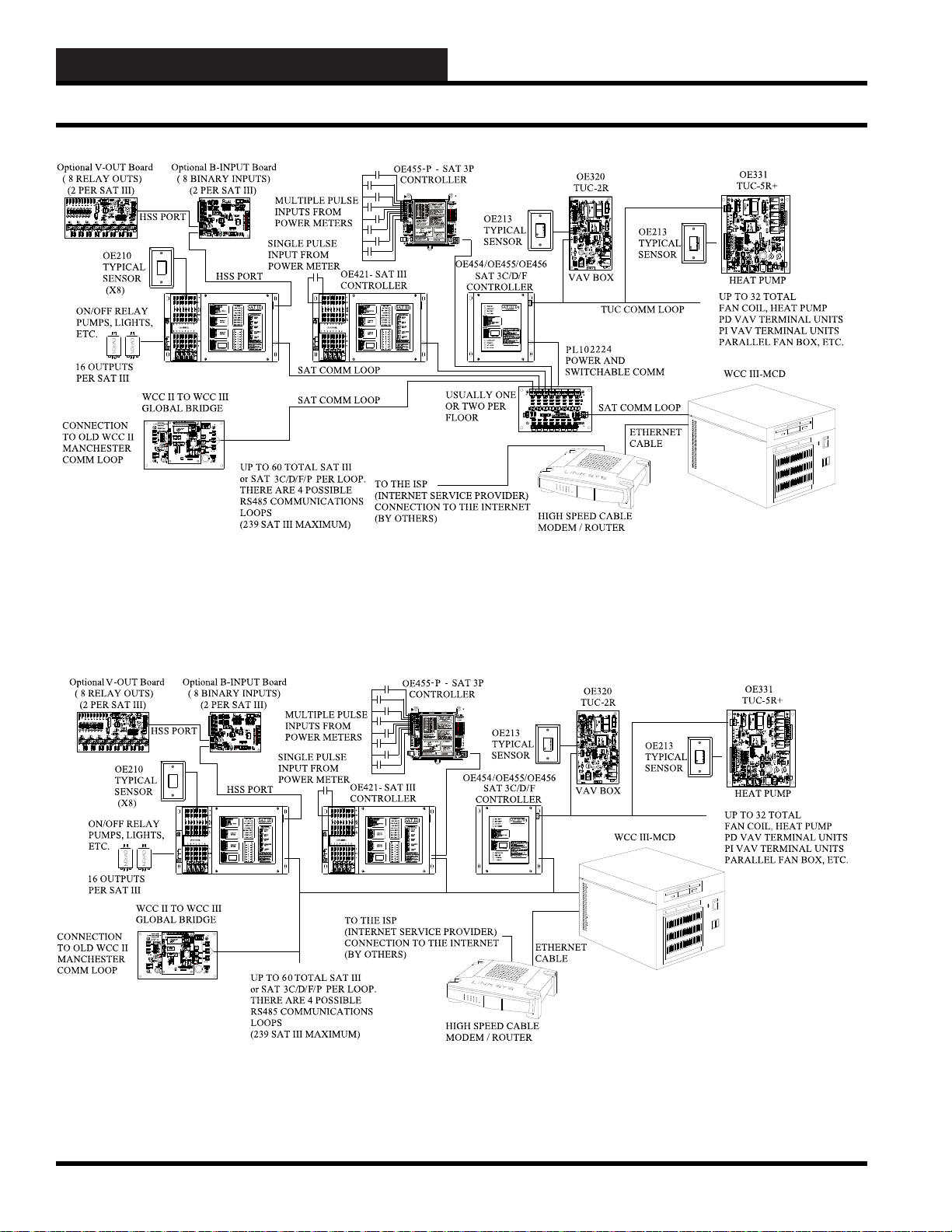
WCC III - MCD Typical System Architecture
Figure 12-5: The WCC III typical system architecture with POWER and SWITCHABLE COMM boards
Figure 12-6: WCC III typical system architecture without the POWER and SWITCHABLE COMM boards
12-8
WCC III Technical Guide
Page 11

12. WCC III INSTALLATION
GUIDE
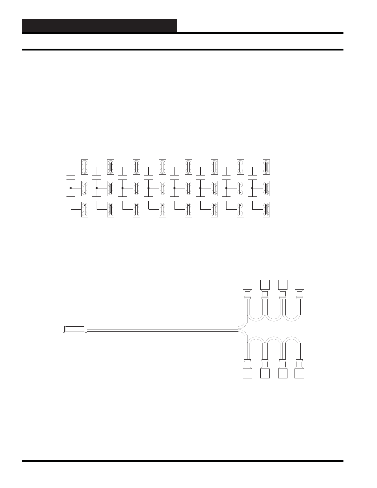
WCC III - MCD Typical System Architecture
The wire that makes up the communication loop should be
shielded. Shielded cable has an aluminum jacket over the wires
that could act as an “antenna” to carry away any “stray” electrical
signals that could interfere with the communication process. The
shield should be grounded throughout the SAT Loop.
The SAT RS-485 communication loop wires are connected to the
“R” and “T” and shield terminals on the satellite controllers using
¼-inch Sta-Con connectors. Make sure the polarity is correct.
That is to say, the wire connected to the “R” and “T” terminal on
the MCD must be connected to the “R” and “T” terminal on the
satellite controllers. If the “R” and “T” and shield wires are crossed,
the WCC III system will not communicate. The shield should be
connected together when the cable is cut in order to terminate the
wires at the satellite controller.
The communication loop wire from the WCC III - MCD is
connected to one of the “R” and one of the “T” terminals on the
satellite controller, which is physically located nearest the WCC
III - MCD. The other “R” and “T” terminals located on the satellite
controller can be used to extend the two-wire loop to the next
satellite controller, or the wires can branch off of a two-wire loop
running through the center of a building as shown in Figure 12-6.
NOTE: The shield wire must be connected at each and every
Satellite Controller also.
WCC III Technical Guide
12-9
Page 12
12. WCC III INSTALLATION
8
7
SATADDRESS
2
1
4
8
A3WIREROOM SENSORWILLNOT
REQUIREALOAD RESISTOR WHEN SET
FORA1 VOLT INPUT .
WattMasterControlsInc.
BINARY
INPUTS
BINARY
INPUTS
L8
ON OFF
128
32
16
64
L4
L3
L2
L1
L6
L5
L7
L11
L12
ON OFF
L10
L9
ON OFF
L15
L16
L14
L13
CH
4
3
5
6
2
1
LOCALSET
STATUS2
STATUS3
STATUS1
HSSXMIT
LOCALSET
LOCALSETDISABLE
BATTON/OFF
PULSEINPUT
OPTION1
TEST
OPTION3
OPTION2
ON OFF
STATUS
HSSREC
SATXMIT
SATREC
ANALOGINPUT
JUMPERSELECTION
A2WIREROOM SENSORWILLREQUIRE
A300OHM LOAD RESI STOR WHEN SET
FORA1 VOLT INPUT .
A4TO2 0 mA SENSOR WILLREQUIREA
50OHMLOAD RES ISTOR WHEN SE T FOR
A1VOLTINPUT, ORA 250 OHM LOAD
RESISTORWHENSETFO R A 5 VOLT INPUT.
CURRENT
INPUT
THERMISTOR
INPUT
0-1V
0-5V
0-10V
THERM
0-1V
0-5V
0-10V
THERM
0TO10V
INPUT
0TO5V
INPUT
0TO1V
INPUT
0-10V
0-1V
0-5V
0-10V
THERM
0-1V
0-5V
THERM
0-1V
0-5V
0-10V
THERM
PROGRAMMABLE CO NTROLL ER
SAT III
H
C
COM
CHANNEL
2134
2134
567
8
5678
V
OUT
GND
L
O
A
D
+V
ATI
10A250VAC~
5A30VDC
SA
VDE
G5Q-1A4
OMRON
DC24V
CHINA
10A250VAC~
5A30VDC
SA
VDE
G5Q-1A4
OMRON
DC24V
CHINA
10A250VAC~
5A30VDC
SA
VDE
G5Q-1A4
OMRON
DC24V
CHINA
10A250VAC~
5A30VDC
SA
VDE
G5Q-1A4
OMRON
DC24V
CHINA
EACHCONTACT
ISRATEDFOR
24VACOR VDC
@.5AMPMAX
0-15VDC
OUTPUT
MINLOAD
IS1KOHM
RESISTIVE
VDCONLY
100VA
TRANSFORMER
SWITCH
DISCONNECT
INTER PANEL
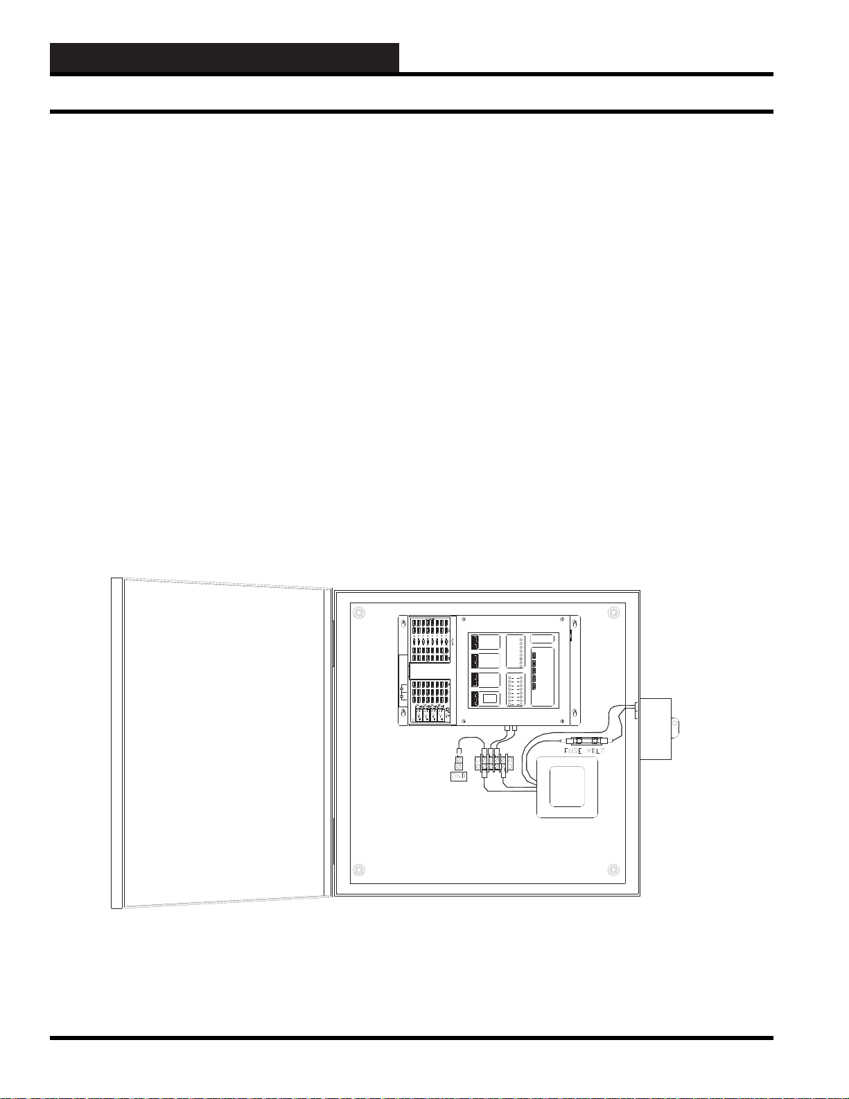
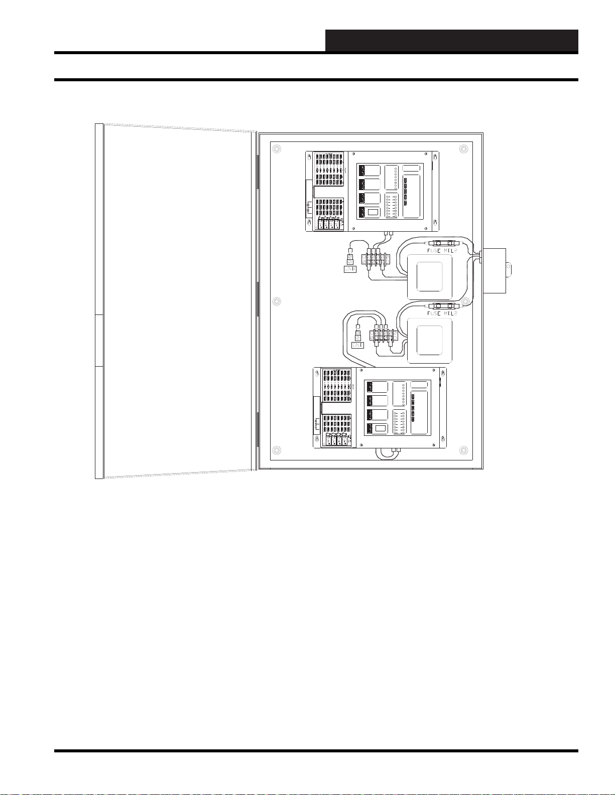
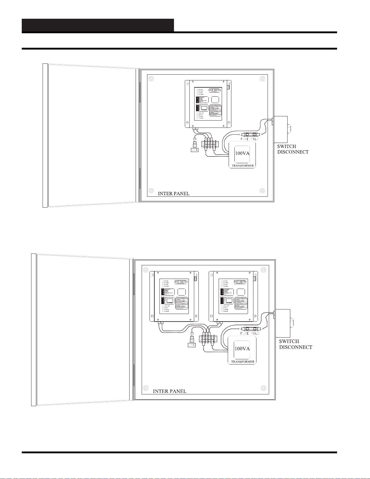
Satellite Controller Enclosure Mounting
Satellite Controller
Mounting in an Enclosure
The satellite controllers are designed to mount in any NEMA 1 or
NEMA 3 standard, six-inch deep, electrical enclosure. Typically,
this is a fi eld-mounted enclosure that contains transformers and
any accessory items required such as a binary input board, V-Out
Binary output board, control relays, etc. The best location for these
satellite panels is mounted on a wall in equipment or storage areas
or rooms at eye level near the controlled loads.
The satellite controllers may be ordered with or without the
NEMA type enclosures. If you order the satellite controller from
the factory without an enclosure, the SAT III and SAT 3C/D/F
dimensions as shown in Figure 12-13 and Figure 12-14 may be
helpful when selecting a suitable NEMA type enclosure.
The satellite controller must be mounted in an electrical enclosure.
If you do not order the satellite controller with an electrical
enclosure, you must provide your own electrical enclosure and
then provide and then install your own fused disconnect switch,
transformer, and terminal strip.
The size of the standard single SAT enclosure is designed to hold
only one satellite controller (or up to two SAT 3C/D/F controllers),
one fused disconnect switch, one transformer, one fi lter, and one
terminal strip which is normally about 15” x 15” x 6” deep with an
inter panel for mounting the SAT III controller, fuse block, 100VA
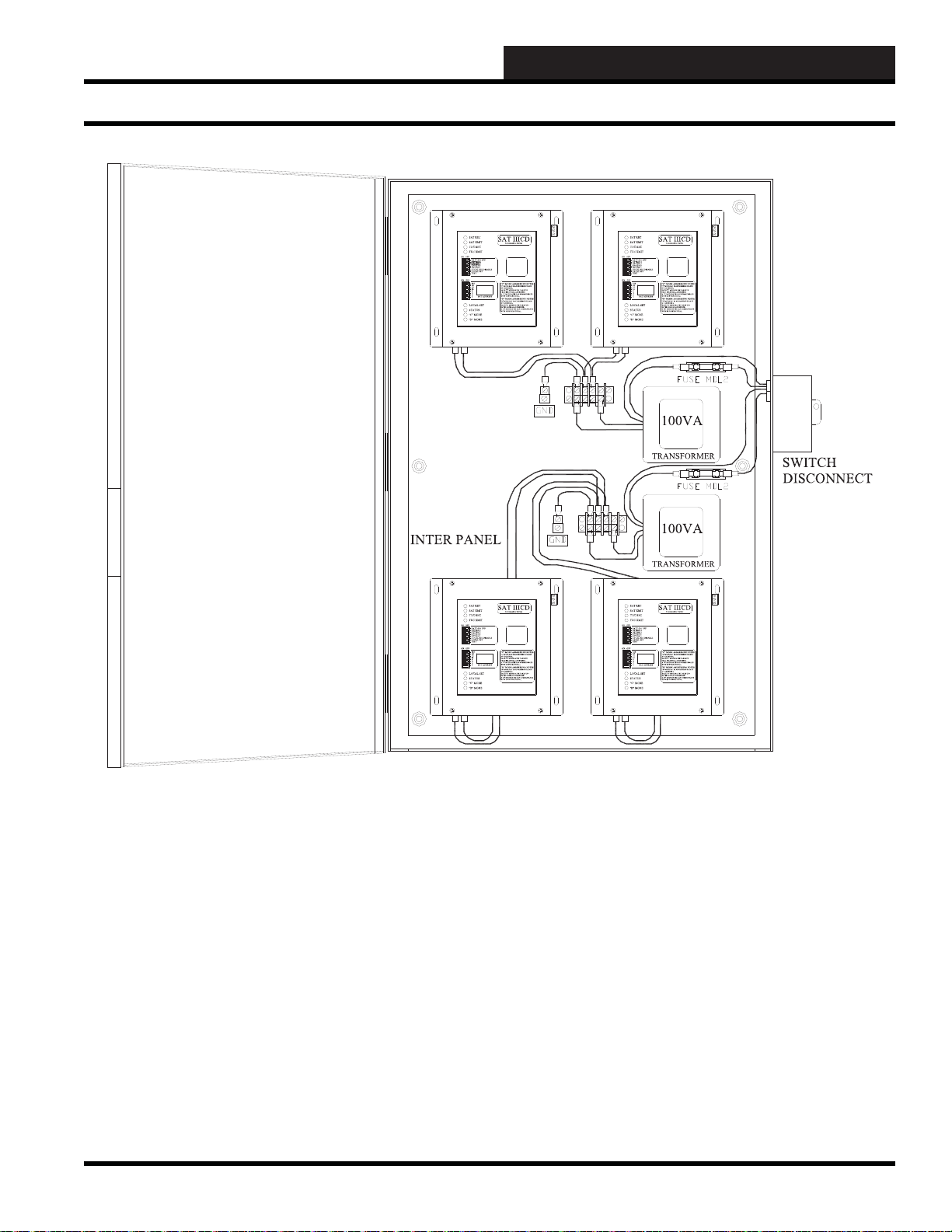
transformer, etc. The size of the standard dual SAT enclosure is
designed to hold two satellite controllers (or up to four SAT 3C/D/F
controllers), one fused disconnect switch, two transformers, two
fi lters, and two terminal strips is 30” x 18” x 6” deep with an inter
panel for mounting the two SAT III controllers, fuse block, 100VA
transformer, etc. If you install the satellite controller yourself,
make sure you leave room for wires that need to be connected to
the following terminals that are located on the sides of the SAT III
satellite controller (minimum recommended clearance is 2 inches):
You can also have both a SAT III controller and up to two SAT
3C/D/F controllers in the same dual enclosure.
24-VAC power source (100VA recommended)
RS-485 Communication loop
SAT III HSS Port connection
Figure 12-7: A typical SAT III controller in a single electrical panel (120-V AC po wered)
12-10
WCC III Technical Guide
Page 13
12. WCC III INSTALLATION
8
7
SATADDRESS
2
1
4
8
A3WIREROOMSENSORWILLNOT
REQUIREALOAD RESISTOR WHENSET
FORA1 VO LT INPUT.
WattMasterControlsInc.
BINARY
INPUTS
BINARY
INPUTS
L8
ON OFF
128
32
16
64
L4
L3
L2
L1
L6
L5
L7
L11
L12
ON OFF
L10
L9
ON OFF
L15
L16
L14
L13
CH
4
3
5
6
2
1
LOCALSET
STATUS2
STATUS3
STATUS1
HSSXMIT
LOCALSET
LOCALSETDISABLE
BATTON/OFF
PULSEINPUT
OPTION1
TEST
OPTION3
OPTION2
ON OFF
STATUS
HSSREC
SATXMIT
SATREC
ANALOGINPUT
JUMPERSELECTION
A2WIRE ROOMSENSORWILL REQUI RE
A300OHM LOAD RESISTOR WHENSET
FORA1 VO LT INPUT.
A4TO20 mA SENSORWILLREQUIREA
50OHMLOAD RESISTOR WHEN SET FOR
A1VOLTINPUT, OR A 250 OHM LOAD
RESISTORWHEN SET FO R A 5 VOLT INPUT.
CURRENT
INPUT
THERMISTOR
INPUT
0-1V
0-5V
0-10V
THERM
0-1V
0-5V
0-10V
THERM
0TO10V
INPUT
0TO5V
INPUT
0TO1V
INPUT
0-10V
0-1V
0-5V
0-10V
THERM
0-1V
0-5V
THERM
0-1V
0-5V
0-10V
THERM
PROGRAMMABLECONTROLLER
SAT III
H
C
COM
CHANNEL
2134
2134
567
8
5678
V
OUT
GND
L
O
A
D
+V
ATI
10A250VAC~
5A30VDC
SA
VDE
G5Q-1A4
OMRON
DC24V
CHINA
10A250VAC~
5A30VDC
SA
VDE
G5Q-1A4
OMRON
DC24V
CHINA
10A250VAC~
5A30VDC
SA
VDE
G5Q-1A4
OMRON
DC24V
CHINA
10A250VAC~
5A30VDC
SA
VDE
G5Q-1A4
OMRON
DC24V
CHINA
EACHCONTACT
ISRATEDFOR
24VACORVDC
@.5AMPMAX
0-15VDC
OUTPUT
MINLOAD
IS1KOHM
RESISTIVE
VDCONLY
100VA
TRANSFORMER
SWITCH
DISCONNECT
8
7
SATADDRESS
2
1
4
8
A3WIREROOM SENSOR WILLNOT
REQUIREALOADRESISTORWHENSET
FORA1VOLTINPUT.
WattMasterControlsInc.
BINARY
INPUTS
BINARY
INPUTS
L8
ON OFF
128
32
16
64
L4
L3
L2
L1
L6
L5
L7
L11
L12
ON OFF
L10
L9
ON OFF
L15
L16
L14
L13
CH
4
3
5
6
2
1
LOCALSET
STATUS2
STATUS3
STATUS1
HSSXMIT
LOCALSET
LOCALSET DI SABLE
BATTON/OFF
PULSEINPUT
OPTION1
TEST
OPTION3
OPTION2
ON OFF
STATUS
HSSREC
SATXMIT
SATREC
ANALOGINPUT
JUMPERSELECTION
A2WIREROOM SENSOR WILLREQUIRE
A300OHMLOADRESISTORWHENSET
FORA1VOLTINPUT.
A4TO 20 mA SENSOR WILL REQUIREA
50OHMLOAD RESISTOR WHEN SETFOR
A1VOLT INPU T, OR A250OHMLOAD
RESISTORWHEN SETFORA5 VOL T INPUT.
CURRENT
INPUT
THERMISTOR
INPUT
0-1V
0-5V
0-10V
THERM
0-1V
0-5V
0-10V
THERM
0TO10V
INPUT
0TO5V
INPUT
0TO1V
INPUT
0-10V
0-1V
0-5V
0-10V
THERM
0-1V
0-5V
THERM
0-1V
0-5V
0-10V
THERM
PROGRAMMABLECONTROLLER
SAT III
H
C
COM
CHANNEL
2134
2134
567
8
5678
V
OUT
GND
L
O
A
D
+V
ATI
10A250VAC~
5A30VDC
SA
VDE
G5Q-1A4
OMRON
DC24V
CHINA
10A250VAC~
5A30VDC
SA
VDE
G5Q-1A4
OMRON
DC24V
CHINA
10A250VAC~
5A30VDC
SA
VDE
G5Q-1A4
OMRON
DC24V
CHINA
10A250VAC~
5A30VDC
SA
VDE
G5Q-1A4
OMRON
DC24V
CHINA
EACHCONTAC T
ISRATEDFOR
24VACORVDC
@.5AMPMA X
0-15VDC
OUTPUT
MINLOAD
IS1KOHM
RESISTIVE
VDCONLY
INTER PANEL
100VA
TRANSFORMER
GUIDE
Satellite Controller Enclosure Mounting
Figure 12-8: Two SA T III controllers in a typical dual electrical panel (120-VA C pow ered)
WCC III Technical Guide
12-11
Page 14
12. WCC III INSTALLATION
Satellite Controller Enclosure Mounting
Figure 12-9: A typical SAT 3C/D/F controller in a single electrical panel (120-V AC po wered)
Figure 12-10: A typical SAT 3C/D/F controller in a (single) dual electrical panel (120-V AC po wered)
12-12
WCC III Technical Guide
Page 15
12. WCC III INSTALLATION
GUIDE
Satellite Controller Enclosure Mounting
Figure 12-11: A typical SAT 3C/D/F controller in a (dual) quad electrical panel (120-V A C pow ered)
WCC III Technical Guide
12-13
Page 16
12. WCC III INSTALLATION
GND 24VAC
100VA
2AMP
MDL
BLK
WHT
L
N
ORG
BRN
BLK
WHT
ORG
BRN
24VAC
GND
GND
24VAC
GND
SIG
+V
FLUSHMOUNT
TYPICAL 7 PLACES
SENSOR
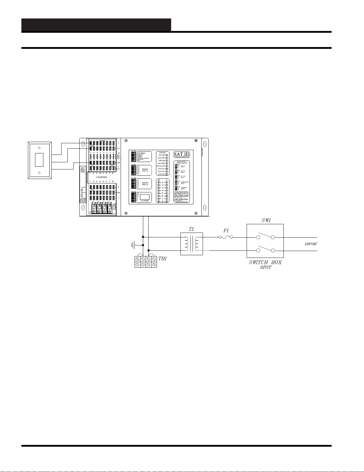
Satellite Controller Wiring
If you order the satellite controller in an enclosure, the factory will
provide and install the wires from the transformer to the satellite.
If you order the satellite controller separately, you must provide a
NEMA panel with an inter panel, disconnect switch, transformer(s),
fusing, terminal block(s), wire, crimp connectors, and then install
the wires from the transformer to the satellite controller. A typical
satellite controller wiring diagram is shown below:
Figure 12-12: SAT III controller typical single panel wiring diagram
12-14
WCC III Technical Guide
Page 17
Satellite Controllers - General Dimensions
8
7
SATADDRESS
2
1
4
8
A3 WIRE ROOM SENSOR WILLNOT
REQUIREA LOAD RESISTOR W HEN SET
FORA 1VOLT IN PUT.
WattMaster Controls Inc.
BINARY
INPUTS
BINARY
INPUTS
L8
ON OFF
128
32
16
64
L4
L3
L2
L1
L6
L5
L7
L11
L12
ON OFF
L10
L9
ON OFF
L15
L16
L14
L13
CH
4
3
5
6
2
1
LOCALSET
STATUS2
STATUS3
STATUS1
HSSXMIT
LOCALSET
LOCALSET DISABLE
BATTON/ OFF
PULSEI NPUT
OPTION1
TEST
OPTION3
OPTION2
ON OFF
STATUS
HSS REC
SATXMIT
SATREC
ANALOGINPUT
JUMPERSELECTION
A2 WIRE ROOM SENSOR WILLREQUIRE
A300OHM LOAD RESISTORWHENSET
FORA 1VOLT IN PUT.
A4 TO 20mA SE NSOR WILLRE QUIRE A
50OHM LOAD R ESISTOR WHENSET FOR
A1VOL T INPUT, OR A 250 OHM LOAD
RESISTORWHENSETFOR A5 VOLTINPUT.
CURRENT
INPUT
THERMISTOR
INPUT
0-1V
0-5V
0-10V
THERM
0-1V
0-5V
0-10V
THERM
0TO10V
INPUT
0TO5V
INPUT
0TO1V
INPUT
0-10V
0-1V
0-5V
0-10V
THERM
0-1V
0-5V
THERM
0-1V
0-5V
0-10V
THERM
PROGRAMMABLE CONTROLLER
SAT III
H
C
COM
CHANNEL
2134
2134
567
8
5678
V
OUT
GND
L
O
A
D
+V
ATI
10A250VAC~
5A30VDC
SA
VDE
G5Q-1A4
OMRON
DC24V
CHINA
10A250VAC~
5A30VDC
SA
VDE
G5Q-1A4
OMRON
DC24V
CHINA
10A250VAC~
5A30VDC
SA
VDE
G5Q-1A4
OMRON
DC24V
CHINA
10A250VAC~
5A30VDC
SA
VDE
G5Q-1A4
OMRON
DC24V
CHINA
123456
123456
+VSENSORS
R1
R212R3R4R5
R6
3456
C
78
C
H
VOUT
GND
7 8
R
R7
R8
78
AT
EACHCONTACT
ISRATEDFOR
24VACORVDC
@.5AMPMAX
0-15VDC
OUTPUT
MINLOAD
IS1K OHM
RESISTIVE
VDCONLY
MADE IN
THEUSA
K16
K15
K14
K13
V16 V15 V14 V13
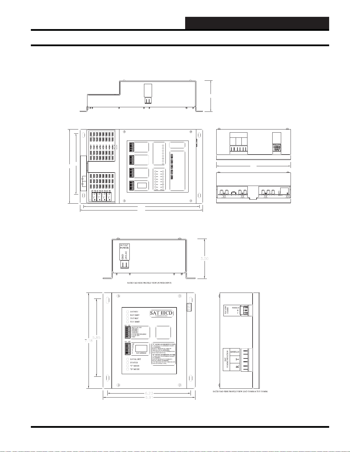
11.90
11.25
5.85
7.18
GND
24 VAC
24 VAC
POWER
SAT
COMMUNICATION
RT
SHIELD
IN /OUT
HSS EXP
COMM
SATIIISIDE PROFILE VIEW (POWER INPUT)
SATIIISIDE PROFILE VIEW (SAT COMM & HSS PORT)
SATIII SIDE PROFILE VIEW (ANALOG IN/OUT - CONTROL OUTPUT)
3.00
7.18
12. WCC III INSTALLATION
GUIDE
Satellite Controller Dimensions
Figure 12-13: SAT III controller dimensions. All dimensions are in inches.
Figure 12-14: SAT 3C/D/F controller dimensions. All dimensions are in inches.
WCC III Technical Guide
12-15
Page 18
12. WCC III INSTALLATION
8
7
SAT ADDRESS
2
1
4
8
A3 WI RE ROOM SENSOR WILL NOT
REQUIRE A LOAD RESISTOR WHE N SET
FORA 1 V OLT INPUT.
WattMaster Controls Inc.
BINARY
INPUTS
BINARY
INPUTS
L8
ON OFF
128
32
16
64
L4
L3
L2
L1
L6
L5
L7
L11
L12
ON OFF
L10
L9
ON OFF
L15
L16
L14
L13
CH
4
3
5
6
2
1
LOCAL SET
STATUS 2
STATUS 3
STATUS 1
HSS XMIT
LOCAL SET
LOCAL SET DISABLE
BATT ON/ OFF
PULSE INPUT
OPTION 1
TEST
OPTION 3
OPTION 2
ON OFF
STATUS
HSS REC
SAT XMIT
SAT REC
ANALOG INPUT
JUMPER SELECTION
A2 WI RE ROOM SENSOR WILL REQUIRE
A30 0 OHM LOAD RESISTOR WHEN SET
FORA 1 V OLT INPUT.
A4 T O 20m A SENSOR WILL REQUIRE A
50OHM LOADRESISTORWHEN SETFOR
A1 V OLT INPUT, OR A 250 OHM LOAD
RESISTORWHENSET FOR A5 VOLT INPUT.
CURRENT
INPUT
THERMISTOR
INPUT
0-1V
0-5V
0-10V
THERM
0-1V
0-5V
0-10V
THERM
0 TO 10V
INPUT
0TO5V
INPUT
0TO1V
INPUT
0-10V
0-1V
0-5V
0-10V
THERM
0-1V
0-5V
THERM
0-1V
0-5V
0-10V
THERM
PROGRAMMABLECONTROLLER
SAT III
H
C
COM
CHANNEL
2134
2134
567
8
5678
V
OUT
GND
L
O
A
D
+V
ATI
10A250VAC ~
5A30VDC
SA
VDE
G5Q-1A4
OMRON
DC24V
CHINA
10A250VAC ~
5A30VDC
SA
VDE
G5Q-1A4
OMRON
DC24V
CHINA
10A250VAC ~
5A30VDC
SA
VDE
G5Q-1A4
OMRON
DC24V
CHINA
10A250VAC ~
5A30VDC
SA
VDE
G5Q-1A4
OMRON
DC24V
CHINA
EACH CONTACT
IS RATED FOR
24VACOR VDC
@ .5 AMP MAX
0-15VDC
OUTPUT
MINLOAD
IS 1K OHM
RESISTIVE
VDCONL Y
SA T III LED Descriptions
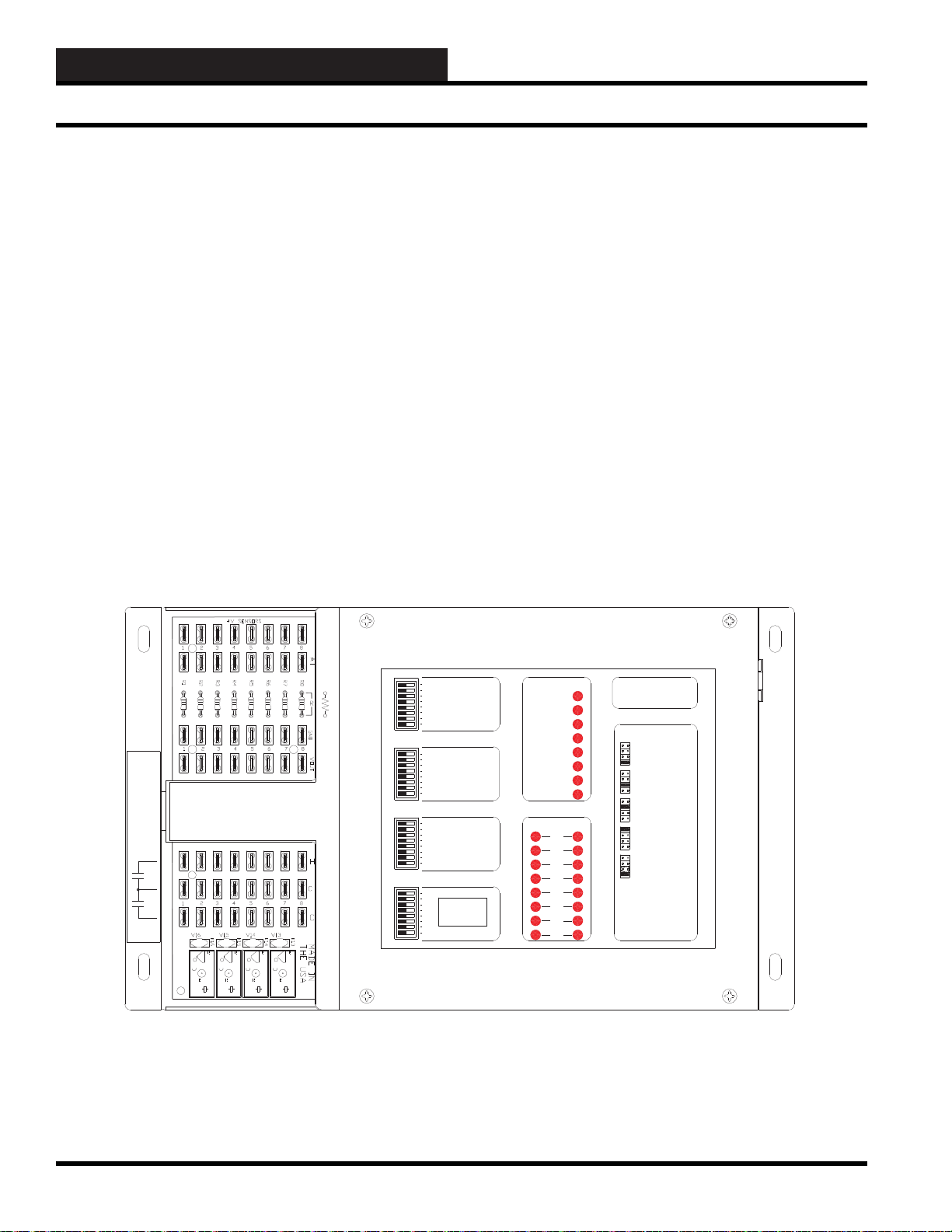
SA T III Controller—LED Information
(SS5003)
The SAT III Controller has 24 LEDs on the cover of the SAT III
controller. The top 8 Status LED functions are as follows:
SAT REC - This LED will be lit when communications are being
received by the SAT III Communications Loop.
SAT XMIT - This LED will be lit when communications are being
transmitted by the SAT III Communications Loop.
HSS REC - This LED will be lit when communications are being
received from the HSS port.
HSS XMIT - This LED will be lit when communications are
being transmitted to the HSS port.
LOCAL SET - This LED will be lit when communications
with the WCC III-MCD has not occurred for at least the last two
minutes. This means that the SAT III is not communicating on the
SAT III communications loop. Setpoint control in the SAT III is
dependent on the LOCAL SET parameters which are programmed
into each control point by the user.
STATUS 1 - LED blinks every 1 second if SAT III is alive.
STATUS 2 - LED blinks every 1 second during power on delay,
and then blinks every 8 seconds when watchdog is enabled.
STATUS 3 - LED blinks for every internal calculation loop
completion.
The lower 16 LEDs display the status of the 16 “H” and “C” Relay
Outputs. The 16 LEDs display the status of the eight “H” and eight
“C” contacts.
Figure 12-15: SAT III LED locations
12-16
WCC III Technical Guide
Page 19

12. WCC III INSTALLATION
GUIDE
SA T III Connection Points
SA T III Controller — Connection
Points
All of the external SAT III connection points are single tab ¼-inch
Sta-Con connectors. With the exception of the “old” connection
method of connecting the Binary Inputs which are 16-pin dip cable
connections and the HSS EXP COMM port which is a 6-pin premade MOLEX type mini-fi t cable connection.
+V Connections.
There are eight +12-VDC connections that power analog type
sensors of which the fi rst seven of these connections are fi xed to
+12VDC only. The eighth +V connector is jumper (JP1) selectable
for either +12VDC, or +24VDC. This (JP1) jumper can be set
to +12VDC, or +24VDC so that the voltage at the eighth +V
connection point is either +12VDC or +24VDC. The +24VDC
is useful when connecting 4-to-20 mA sensors that require a
connection voltage greater than +12VDC. You may connect up to
eight 4-to-20 mA sensors to this eight +V (+24VDC) connection
point. This JP1 jumper is located under the cover of the SAT III
controller, just to the right of the eighth +V connector.
A TI Connections
These eight connections are connection points for ATI #1 to ATI #8
analog inputs. ATI is the acronym for Analog Temperature Input.
These eight connection points are for Analog Inputs. This is where
analog type sensors are connected to the SAT III controller. The
types of sensors inputs that are supported on the SAT III controllers
are: 0-1V, 0-5V, 0-10V, 10K Type 3 Thermistor, 4-20mA (On both
the 0-1V, and 0-5V inputs). There are also eight Analog Input
selection jumpers that are located under the cover of the SAT III
controller near the Analog Inputs that actually set the type input
voltage ranges for each of the eight analog inputs. These Analog
Input selection jumpers are labeled JO1 to JO8. JO1 corresponds
to analog input #1, JO2 corresponds to analog input #2, JO3
corresponds to analog input #3, JO4 corresponds to analog input
#4, JO5 corresponds to analog input #5, JO6 corresponds to analog
input #6, JO7 corresponds to analog input #7, JO8 corresponds
to analog input #8. Each of these Analog Input selection jumpers
has four jumper options: 0-1V, 0-5V, 0-10V, and THERM. See
Figure 12-34 and 12-35 for further wiring details. See Section 3
for further programming instructions.
GND Connections
These GND connections are analog ground common connection
points for all of the analog input (ATI), and analog output (VOUT)
connections.
VOUT 1 to V OUT 8 Connections
These eight analog outputs are set up to provide 0 to +15 DC
Volts outputs at up to 15 milli-amps per output. These outputs are
typically used to drive a VFD, 0-10VDC or 2-10VDC actuator or
valve. VOUT is the acronym for Voltage Output. See Section 3 for
additional programming instructions.
H 1 to H 8 Connections
The eight “H” connection points of the SAT III controller were
originally classifi ed and labeled as “HEAT” contacts starting with
the SAT 0, SAT I, and SAT II controllers. They do not need to
be used only for “HEAT” contacts, as these contacts are general
purpose relay outputs. There is a load protection device called a
varistor across each of the eight “H” output connections that limit
the allowable voltage to no more than 32 volts AC\DC maximum
at 1 amp current draw for each contact. Attempting to switch
any voltage greater than 32 Volts, or current draws of more than
1 amp per contact could and will result in damage to the SAT
III controller. These “H” and “C” contact outputs are meant to
control tri-state actuators, contactors, relays, solenoids, and the PI
board AKA “ECC II ANALOG OUTPUT” board that WattMaster
Controls used to manufacture. See Figure 12-18 for further wiring
details. See Section 3 for additional programming instructions.
COM 1 to COM 8 Connections
The COM1 connection point is a common connection point for
H1 and C1 Relays. None of the COM connections are connected
to any of the other seven COM connection points. A jumper cable
is available to connect all of the COM connection points together.
Each corresponding “H” and “C” contact are connected to a single
corresponding “COM” connection point. So “H1” and “C1” are
connected to “COM1”, “H2” and “C2” are connected to “COM2”,
etc. See Figure 12-18 for further wiring details.
WCC III Technical Guide
12-17
Page 20

12. WCC III INSTALLATION
SA T III Connection Points
C 1 to C 8 Connections
The eight “C” connection points of the SAT III controller were
originally classifi ed and labeled as “COOL” contacts starting with
the SAT 0, SAT I, and SAT II controllers. They do not need to
be used only for “COOL” contacts, as these contacts are general
purpose relay outputs. There is a load protection device called
a varistor across each of the eight “COOL” output connections
that limits the allowable voltage to no more than 32 volts AC\DC
maximum at 1 amp current draw for each contact. Attempting to
switch any voltage greater than 32 Volts, or current draws of more
than 1 amp per contact could and will result in damage to the SAT
III controller. These “H” and “C” contact outputs are meant to
control tri-state actuators, contactors, relays, solenoids, and the PI
board AKA “ECC II ANALOG OUTPUT” board that WattMaster
Controls used to manufacture. See Figure 12-18 for further wiring
details. See Section 3 for additional programming instructions.
Binary Inputs
The SAT III controller has two sets of eight-position dipswitches
on its front panel labeled L1 - L8 and L9 - L16. Switches L1-L8 are
housed together in one dipswitch, and switches L9-L16 are housed
together in another dipswitch. For the old connection method one
dipswitch is removed for each Binary Input with Time Delay board,
and is then replaced with a ribbon cable which connects the Binary
Input with Time Delay board to the SAT III controller. The binary
devices to be monitored are then wired to the terminal strip of the
Binary Input with Time Delay board. The Binary Input with Time
Delay board requires a 24-VAC power source. Warning you must
observe polarity on the 24-VAC and GND connections of both the
Binary Input with Time Delay board and the SAT III controller,
as the grounds must be the same. Or, an alternative connection
method to the SAT III controller is now provided by the 6-pin HSS
expansion port on the side of the SAT III controller. See Figures
12-26, 12-27, & 12-28 for further wiring details.
24V AC & GND Connection
Located on the bottom side of the SAT III controller is a 24 VAC
and GND connection. This is the main power connection to the
SAT III controller. Each SAT III Controller draws - 15VA. External
relays and contactors are not included, but need to be considered
for total VA draw. The GND connection points must be the same
between all of the externally powered expansion boards and the
SAT III Controller. See Figure 12-27 for further wiring details.
SA T Communica tion Connection
These connection points are for wiring of the RS-485 communication
loop. There are two “T” (Transmit) connections, two “R” (Receive)
connections and two “SHIELD” connection points. There are two
connection points provided for each connection for easy “daisy
chaining” to the next Satellite Controller. When connecting the
RS-485 wiring from SAT III to SAT III or SAT 3C/D/F, or SAT 3P
controller the wiring connections are as follows: connect “R” TO
“R”, “T” TO “T”, AND “SHIELD” TO “SHIELD” OR “SH”. The
RS-485 wire specifi cations are plenum-rated, jacketed stranded
18-gauge, 2-wire twisted pair with shield. 18-gauge stranded wire
is mandatory to ensure a good connection with the ¼-inch Sta-Con
connectors which are used to terminate the wires at the WCC III MCD and at the satellite controllers.
HSS EXP COMM Connection
The HSS EXP (Expansion) Port enables newer versions of the
satellite expansion boards, most notably the Binary Input with
Time Delay Board and V-Out RELAY Board to work without
connecting the previous way (separate power and hard wiring was
required). The SAT III has a single connection via the built-in HSS
EXP port on the side of the SAT III. It is designed to connect and
power up 5 HSS Expansion Boards. Connecting more than 5 HSS
Boards is possible, but each additional board will require a 24VAC
power supply.
The HSS EXP port provides power and ground, along with
communications on a 6-pin pre-made MOLEX type mini-fi t cable
connection. This cable is made with 16-gauge wire.
Each HSS Expansion Board has an 8-position address dipswitch
that is used to set up the function of the board.
The HSS EXP port can be daisy chained to the next board. The
HSS cable connections allow the HSS expansion boards to be
located up to 150 feet away from the SAT III Controller.
HSS connection cables are available in the following sizes: 6-inch,
12-inch, 18-inch, 3 feet, 25 feet, 40 feet, 80 feet, and 120 feet.
12-18
WCC III Technical Guide
Page 21
12. WCC III INSTALLATION
8
SAT ADDRESS
2
1
4
ON OFF
128
32
16
64
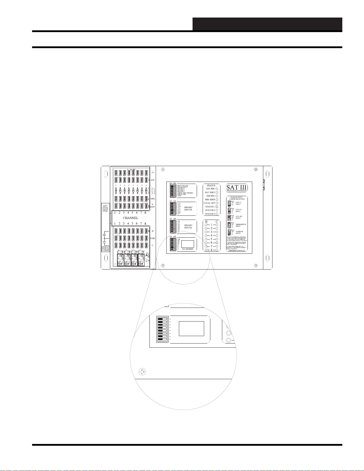
SAT III ADDRESS SWITCH
GUIDE
SA T III Addressing
Addressing (Numbering) of SA T III
Controllers
The WCC III system can have up to 239 SAT III controllers. In
order for the central computer to communicate properly with each
individual SAT III controller, each controller must be assigned a
separate number, or address. The number is assigned by placing
the small dip switches on the front of the SAT III controller marked
“SAT ADDRESS” in the proper position.
The address dip switches are additive; that is to say placing
switches 1 and 2 in the ON position will cause the SAT III
controller to be identifi ed as satellite controller number 3. The SAT
III controller looks at the position of these switches only when it
is going through its initialization process after being powered up.
Simply changing the switch positions on a SAT III controller that is
currently “on-line” will not change its number. The switches need
to be placed in the proper position before powering up the SAT III
controller, or the SAT III must be powered down and then back up
for the SAT III to “read” the new position of the switches. When
placing the switches in the desired position, make sure the switch
has “clicked” into place and is properly seated.
Figure 12-16: SAT III address switch loca tion
WCC III Technical Guide
12-19
Page 22

12. WCC III INSTALLATION
SA T III Addressing
Care must be taken to ensure that two SAT III controllers do not
have the same address. When this condition is present, the central
computer does not know where to send the information, and the
information that should be sent to the SAT III controller is usually
lost.
You should be aware of the symptoms caused by two satellite
controllers having the same number. Let’s consider a new job in
which the satellite controllers have not yet been programmed and
2 SAT III controllers are named number #3. When you call up
satellite controller #3 to enter data, everything will appear to be
fi ne. You will be able to enter data on the screens as if nothing is
wrong. However, when you leave a screen and then return to the
same screen, all of the data you entered will be missing. Also, if
you fi nish programming the analog inputs for example, and then
go to the analog input summary screen to review your inputs, all
of the data you have entered will be missing.
Another situation that you might encounter is adding a SAT III
controller to an existing system and accidentally giving it the same
number as a SAT III presently “on-line.” Again, when you begin
to program the new SAT III controller, everything will appear fi ne
until you leave a screen or if you go to a summary screen. Only
now, all of the data is usually not missing. Generally, you get parts
of your data back and parts will be missing.
If you suspect you might have two SAT III controllers with the
same address (number 3 for example) the best thing to do is go
to the SAT III controller that you know is number 3, and remove
the 2-wire RS-485 communication loop from it. Then, go back to
the computer and call up satellite controller #3. If the computer
can still “talk” to satellite controller #3, there is another satellite
controller that is addressed #3 connected somewhere on the RS485 communication loop.
If a satellite controller was accidentally addressed #3, there will
be a satellite number missing. For example, if satellite controller
#7 was accidentally misaddressed to #3, satellite controller #7 will
not be present. One way of telling which satellite controllers are
“on-line” is to go to the Satellite Summary Screen (see Section
3) and see which satellite controllers the computer recognizes as
being “on-line.”
If satellite controller #7 was accidentally miss-addressed #3, there
would not be a satellite controller at address #7, and the computer
will give a “Non-Existing” message for satellite controller #7.
Option 1, 2, and 3 Switches
Option switches 2 and 3 do nothing. But, the SAT III controller
option “1” switch selects the A-to-D converter type that is on the
mother board. With the switch turned OFF, the A-to-D curve is
selected for the Maxim MAX147 part, and with the switch turned
“ON” for the TI-ADS7844 (BB marked) the software will use the
special A-to-D curve for the TI-ADS7844 part. See Section 3 for
proper A-to-D identifi cation.
BA TT ON/OFF s witc h
This switch is used to turn the Battery (Rechargeable Super cap) ON
and OFF to the SRAM located inside of the SAT III processor.
Since version 2.00 of the Satellite software the non-volatile
memory is now also stored in the EEPROM, instead of the SRAM,
and upon power up the memory is read from the EEPROM back
into the SRAM. This switch is not of any importance anymore.
Local Set Switch
When the LOCAL dipswitch is in the ON position, the SAT
III controller will operate according to their predefi ned user
programmed “local set” setpoints. That is, if the SAT III controller
was programmed by the user to correctly operate when and if the
WCC III - MCD is off-line or disconnected.
Local Set Disable Switch
When the LOCAL SET Disable dipswitch is in the ON position,
the SAT III controller will operate according to their predefi ned
user programmed “On” setpoints. That is, if the SAT III controller
were programmed by the user to correctly operate when and if the
WCC III - MCD is off-line or disconnected.
Test Switc h
The test mode is active only if the TEST dipswitch is in the ON
position. The word “TEST” can be input as the binary value within
the SAT III. Example of use would be if the user programmed the
word “TEST” into one of the control point values in the SAT III
controller to check the operation of the SAT III controller with an
alternate setpoint or schedule, the user could then place the TEST
switch in the ON position to make this function work with out
physically having to go back to the front-end computer to change a
setpoint via the computer.
12-20
WCC III Technical Guide
Page 23
12. WCC III INSTALLATION
8
7
SAT ADDRESS
2
1
4
8
A3 WI RE ROOM SE NSOR WILL NO T
REQUIREA LOADRESIST OR WHEN SET
FORA 1VOLT INPUT.
WattMaster Controls Inc.
BINARY
INPUTS
BINARY
INPUTS
L8
ON OFF
128
32
16
64
L4
L3
L2
L1
L6
L5
L7
L11
L12
ON OFF
L10
L9
ON OFF
L15
L16
L14
L13
CH
4
3
5
6
2
1
LOCAL SET
STATUS 2
STATUS 3
STATUS 1
HSS XMIT
LOCAL SET
LOCAL SET DISABLE
BATT ON/ OFF
PULSE INPUT
OPTION 1
TEST
OPTION 3
OPTION 2
ON OFF
STATUS
HSS REC
SAT XMIT
SAT REC
ANALOG INPUT
JUMPER SELECTI ON
A2 WI RE ROOM SE NSOR WILL REQUIRE
A300 OHMLOAD RESISTORWHEN SET
FORA 1VOLT INPUT.
A4TO20mASENSORWILLREQUIREA
50OHM LOADR ESISTOR WHEN SET FOR
A1 VO LT INPUT , OR A 250 OHML OAD
RESISTORWH EN SET FOR A 5 VOL T INPUT.
CURRENT
INPUT
THERMISTOR
INPUT
0-1V
0-5V
0-10V
THERM
0-1V
0-5V
0-10V
THERM
0TO10V
INPUT
0TO5V
INPUT
0TO1V
INPUT
0-10V
0-1V
0-5V
0-10V
THERM
0-1V
0-5V
THERM
0-1V
0-5V
0-10V
THERM
PROGRAMMABLECONTROLLER
SAT III
H
C
COM
CHANNEL
2134567
8
10A250VAC ~
5A30VDC
SA
VDE
G5Q-1A4
OMRON
DC24V
CHINA
10A250VAC~
5A30VDC
SA
VDE
G5Q-1A4
OMRON
DC24V
CHINA
10A250VAC ~
5A30VDC
SA
VDE
-1A4
ON
24V
CHINA
10A250VAC ~
5A30VDC
SA
VDE
G5Q-1A4
OMRON
DC24V
CHINA
NTACT
FOR
VDC
AX
GUIDE
SA T III Relay Outputs
SA T III Relay Outputs
The standard SAT III controller is capable of providing 16 binary
(on/off) relay outputs. These 16 relay outputs are for driving pilot
duty relays. There is a load protection device called a varistor
across each of the 16 output connections that limits the allowable
voltage to no more than 32 volts AC\DC maximum at 1.0 or 1 amp
current draw for each contact.
Attempting to switch any voltage greater than 32 Volts, or current
draws of more than 1.0 or 1 amp per contact could and will result
in damage to the SAT III controller. These “H” and “C” contact
outputs are meant to control tri-state actuators, contactors, relays,
solenoids, and the PI board AKA “ECC II ANALOG OUTPUT”
board that WattMaster Controls used to manufacture. These relay
outputs can be programmed in three different types of modes of
basic operation: Time Clock, Dual Limit, and EA Mode. See
Section 3 for further details on Satellite programming instructions.
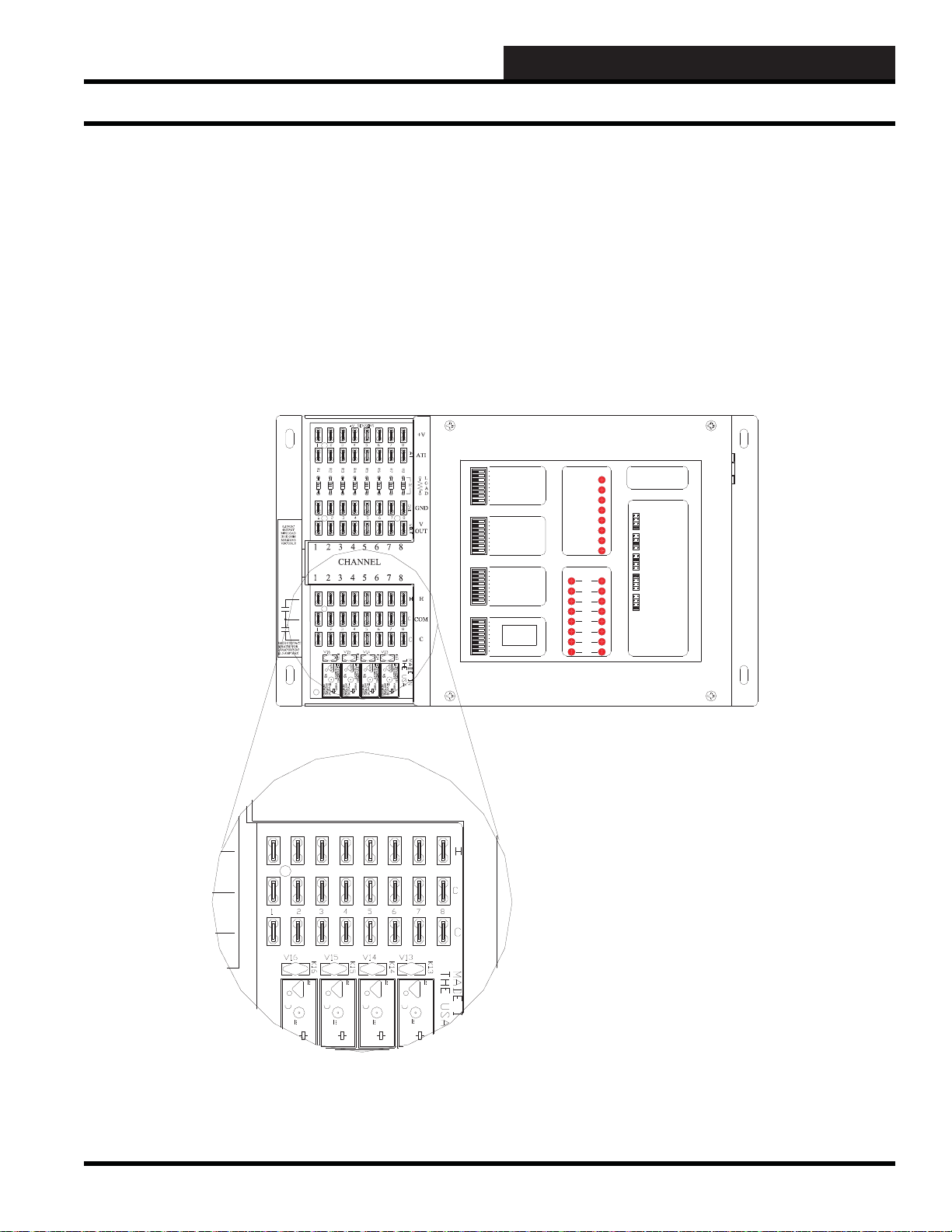
Figure 12-17: SAT III “H” and “C” control output wiring connections
WCC III Technical Guide
12-21
Page 24
12. WCC III INSTALLATION
H
COM
C
12345678
12345678
SA T III Relay Outputs
The terminals for the binary outputs are found at the lower lefthand corner of the SAT III controller and are labeled “H”, “COM”,
and “C”. The relay contact can make or break a 24-VAC or 24VDC circuit between the COM to H or COM to C terminals.
The COM to H contacts are referred to as XXXK1h-K8h in the
WCC III point addressing scheme, and the COM to C contacts
are referred to as XXXK1c-K8c in the WCC III point addressing
scheme. XXX is the Satellite address number 1 to 239, “K” stands
for contact, and the numbers 1-8 stand for the channel on the SAT
III controller.
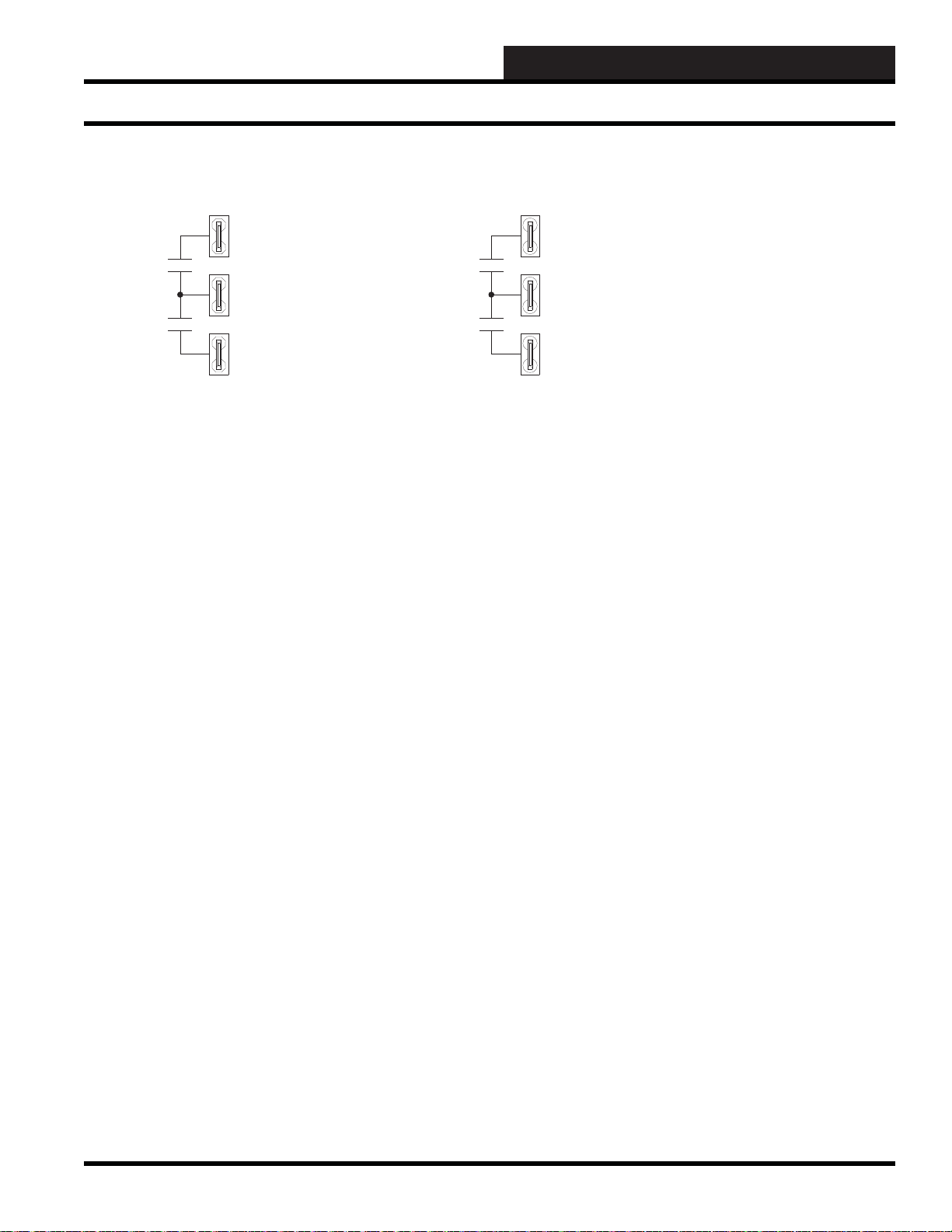
Each “H” and “C” contact connection has a “COM” connection
associated with it. Please note that each one of the sets of the
corresponding “H” and “C” contacts are also isolated from each
other. The “COM” connection means common. When wiring
the control outputs, typically all of the “COM” connections are
wired together, using the supplied jumper wire (PL100867). This
“COM” common connection can either be connected to 24VAC /
24VDC or GROUND depending on the application.
Figure 12-18: SAT III “H” and “C” control output schematic
Figure 12-19: A control output common jumper wire is provided (PL100867) for connecting the eight “COM”
connections together
The pre-made control output common jumper wire is provided
in the initial spare parts kit that came with the SAT III controller.
This spare parts kit contains various input load resistor packs,
spare fuse, and the control output common jumper. The spare parts
kit is WattMaster part number PL102029.
12-22
WCC III Technical Guide
Page 25
1
1
1
1
COM - 24VAC COM - GROUND
H
C
H
C
Figure 12-20: COM connection as 24 VAC or as GR OUND
12. WCC III INSTALLATION
SA T III Relay Outputs
GUIDE
The “COM” or common connection point can either be connected
to 24 VAC / 24 VDC or GROUND. It is basically a point of view
of turning power “on” to a device, or removing “ground” going
to the device. It makes no difference, as both methods will work
equally well, and really depends on the application you are trying
to control.
WCC III Technical Guide
12-23
Page 26
12. WCC III INSTALLATION
Proportional-Integral (PI) Output Board
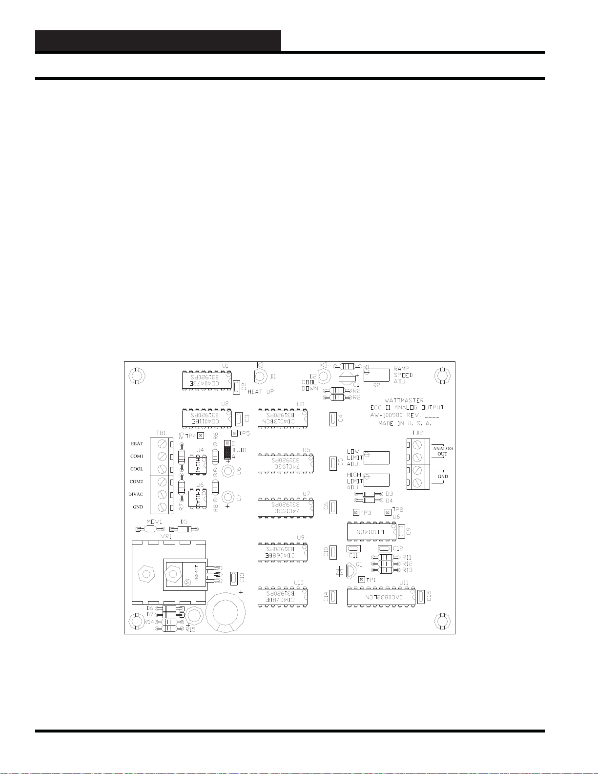
Proportional-Integral (PI) Output
Board
The Proportional-Integral (PI) Board is a separate integrated circuit
board which works in conjunction with the SAT III controller to
convert a pair of SAT III binary outputs to a varying DC voltage
signal. When one contact on the SAT III controller closes, the
voltage supplied by the PI board will ramp down at a pre-set rate.
When the other SAT III contact closes, the voltage ramps up at
the preset rate. When both contacts are open, the voltage supplied
by the PI board will remain at its present value. The maximum
DC voltage range is 0-14.5 volts, and the minimum allowable
resistance of the controlled device is 1000 ohms. See Section 3 for
further details on Satellite programming instructions.
Figure 12-21: ECC II Analog Output Board
12-24
WCC III Technical Guide
Page 27

12. WCC III INSTALLATION
GUIDE
PI Board Connection Points
The DC voltage range along with the ramp speed is set at the PI
board. The ramp speed can be adjusted from 23 seconds to 38
minutes, and the maximum range is 0-14.5 volts DC.
To control a VFD drive from a SAT III controller using the
Proportional-Integral board, you must use two control outputs and
a circuit board (PI Board) that we no longer make. WattMaster
Controls does not make the PI Output Board anymore, but Kele
makes a similar circuit board that should work. It is a Tri-State-toAnalog Output circuit board (Kele Part # PWA-2T).
If only one contact closure is available to drive the PI Board, move
jumper J01 on the WattMaster PI board to the B-C position and use
the SAT III’s control output in the Dual Limit mode to control the
PI Board. Although when using this method with the WattMaster PI
Board, the DC voltages supplied by the WattMaster PI Board will
either be increasing or decreasing at the set ramp speed depending
on if the contact is open or closed.
The Global Analog Mode 9 Dual Ramp Screen was created to help
emulate the old WattMaster PI board in software. It basically uses
the control set points of two control outputs on a satellite controller
to control a single analog output on a satellite controller and should
be used when controlling an analog actuator or VFD that needs to
have an analog control setpoint. See Section 3 for further details on
Satellite programming instructions.
The Proportional-Integral (PI) Board connection points
All of external connections to Proportional-Integral (PI) Board
connection points are non de-pluggable screw-cage type of wire
clamped based terminal blocks.
24 V AC (TB1-5) & GND (TB1-6)
ANALOG OUT (TB2-1) & GND (TB2-3&4)
The “ANALOG OUT” and “GND” terminals supply the DC
voltage from the PI board.
Adjust Minimum Voltage
The PI board is factory set for a minimum voltage of 0 VDC +/-
0.2 VDC. If you want a minimum voltage other than 0 VDC, you
can reset it by adjusting the potentiometer (pot) labeled “R9.” The
voltage between test point #3 (labeled “TP #3” on the PI board)
and ground is set 300 mV lower than the desired minimum voltage.
That is to say, if you want 5 VDC as the minimum voltage to be
supplied between the “ANALOG OUT” and “GND” terminals,
adjust pot “R9” to get 4.7 VDC between “TP #3” and “GND.”
NOTE: The minimum voltage setpoint must be lower than the
maximum voltage setpoint.
Adjust Maximum Voltage
The PI board is factory set for a maximum voltage of 14.5 VDC
+/- 0.2 VDC. If you want a maximum voltage other than 14.5
VDC, you can reset it by adjusting the potentiometer (pot) labeled
“R10.” The voltage between test point #2 (labeled “TP #2” on the
PI board) and ground is set at 300 mV above the desired maximum
voltage. That is to say, if you want a maximum voltage of 10 VDC
to be supplied by the “ANALOG OUT” and “GND” terminals,
adjust pot “R10” to get 10.3 VDC between “TP #2” and “GND.”
NOTE: The maximum voltage setpoint must be higher than
the minimum voltage setpoint.
The PI board requires a 24 VAC power supply which is connected
to these terminals. The PI board is generally powered by the same
24 VAC transformer that powers the satellite controller. The GND
connection points must be the same between the PI board and the
SAT III Controller.
HEA T (TB1-1) & COM1 (TB1-2)
When 24 volts AC is supplied between the “HEAT” and “COM1”
terminals, the DC voltage supplied by the PI board will start
increasing at the set ramp speed.
COOL (TB1-1) & COM2 (TB1-4)
When 24 volts AC is supplied between the “COOL” and “COM2”
terminals, the voltage supplied by the PI board will start decreasing
at the set ramp speed.
WCC III Technical Guide
Adjust “Ramp” Speed
The ramp speed is the time it takes for the DC voltage between
the “ANALOG OUT” and “GND” terminals to change from the
minimum voltage to the maximum voltage and vice versa. The ramp
speed is factory set at about 19 minutes. If you want a ramp speed
other than 19 minutes, you can reset it by adjusting the potentiometer
(pot) located at R2. When R2 is fully counterclockwise, the ramp
speed is 38 minutes (+/- 10%). When R2 is fully clockwise, the
ramp speed is 23 seconds (+/- 10%). As the voltage is ramping up,
the small light labeled D1 will fl ash and as the voltage is ramping
down, the small light labeled D2 will fl ash.
12-25
Page 28

12. WCC III INSTALLATION
8
7
SAT ADDRESS
2
1
4
8
A3 WI RE ROOM SENSOR WILL NOT
REQUIREA LOAD RESISTOR WHEN SET
FORA 1 VOLT INPUT.
WattMaster Controls Inc.
BINARY
INPUTS
BINARY
INPUTS
L8
ON OFF
128
32
16
64
L4
L3
L2
L1
L6
L5
L7
L11
L12
ON OFF
L10
L9
ON OFF
L15
L16
L14
L13
CH
4
3
5
6
2
1
LOCAL SET
STATUS 2
STATUS 3
STATUS 1
HSS XMIT
LOCAL SET
LOCAL SET DISABLE
BATT ON/OFF
PULSEINPUT
OPTION 1
TEST
OPTION 3
OPTION 2
ON OFF
STATUS
HSS REC
SAT XMIT
SAT REC
ANALOG INPUT
JUMPER SELECTION
A2 WI RE ROOM SENSOR WILL REQUIRE
A30 0 OHM L OAD RESIST OR WHEN SET
FORA 1 VOLT INPUT.
A4 TO 20 mA SENSOR WILL REQUI RE A
50O HM LOAD RESISTOR WHEN SET FOR
A1 VOLT INPUT, OR A 250 OHM LOAD
RESISTOR WHEN SET FOR A 5 VOLT INPUT.
CURRENT
INPUT
THERMISTOR
INPUT
0-1V
0-5V
0-10V
THERM
0-1V
0-5V
0-10V
THERM
0TO10V
INPUT
0TO5V
INPUT
0TO1V
INPUT
0-10V
0-1V
0-5V
0-10V
THERM
0-1V
0-5V
THERM
0-1V
0-5V
0-10V
THERM
PROGRAMMABLE CONTROLLER
SAT III
24VAC 120VAC
120VAC WIRING
BY OTHERS
TO OTHER
SAT III OR TO
WCC III - MCD
24VAC
GND
TO OTHER
SAT III OR TO
WCC III - MCD
WIRE "T" TO "T"
"R" TO "R"
"SHD" TO "SHD"
WARNING: OBSERVE POLARITY
BETWEEN THE SAT III AND THE ECCII
ANALOG OUTPUT BOARD - GROUND
CONNECTIONS MUST BE THE SAME.
ECC II ANALOG OUTPUT BOARD
PI Board Typical Wiring Connections
If you want to test the ramp speed, disconnect all wires from the
“HEAT,” “COM1,” “COOL,” and “COM2” terminals and use a
volt meter to measure the DC voltage between “ANALOG OUT”
and “GND” as you jumper test point #4 (TP #4) to ground.
The voltage should increase from the minimum to the maximum
voltage during the set time interval. Then, remove the jumper from
“TP #4” and jumper “TP #5” to “GND.” The voltage between the
“ANALOG OUT” and “GND” terminals should decrease from the
maximum to the minimum voltage during the set time interval.
Figure 12-22: ECC II Analog Output typical wiring connections to a SAT III controller
12-26
WCC III Technical Guide
Page 29

12. WCC III INSTALLATION
GUIDE
Old SA T II Type Binary Input with Time Delay Board
Sequence of Operation
When the SAT III controller makes COM to H, 24 VAC is supplied
to the “HEAT” terminal on the PI board which causes the DC output
voltage supplied by the PI board to increase the output voltage at
the preset rate.
When the SAT III controller makes COM to C, 24 VAC is supplied
to the “COOL” terminal on the PI board which causes the DC
output voltage supplied by the PI board to decrease the output
voltage at the preset rate. When both the COM to H and COM to C
terminals are open on the SAT III controller, the DC output voltage
supplied by the PI board will remain at its present value.
Previous “Old” SA T II Type Binary
Input with Time Delay Board
The SAT II type Binary Input with Time Delay board is an optional
integrated circuit board which can interface with the “old” SAT II
as well as the “new” SAT III controllers to allow it to monitor the
status of remote mounted binary (on/off) devices such as switch
closures, air fl ow switches, etc. One binary input board enables the
SAT II or SAT III controller to monitor up to 8 binary inputs, and 2
binary input boards can be used with 1 SAT II or SAT III controller
for a total of 16 binary inputs per SAT II or SAT III controller.
The SAT III controller comes standard with two eight-position
dipswitch switches on its front panel labeled L1 - L8 and L9 - L16
which are in effect manually controlled binary inputs. The SAT
III controller monitors the on/off status of these switches and can
control and/or alarm based on the position of these dipswitches.
The Binary Input with Time Delay board allows the eight-position
dipswitches to be replaced with a terminal connection points which
will accept wiring for remote-mounted binary input devices.
The SAT III controller has two sets of eight-position dipswitches
on its front panel labeled L1 - L8 and L9 - L16. Switches L1-L8 are
housed together in one dipswitch, and switches L9-L16 are housed
together in another dipswitch. One of the dipswitches is removed
for each Binary Input with Time Delay board, and is then replaced
with a ribbon cable that connects the Binary Input with Time Delay
board to the SAT III controller. The binary devices to be monitored
are then wired to the terminal strip of the Binary Input with Time
Delay board. The Binary Input with Time Delay board requires a
24 VAC power source. Warning: You must observe polarity on the
24 VAC and GND connections of both the Binary Input with Time
Delay board and the SAT III controller, as the grounds must be the
same. See Section 3 for further details on Satellite programming
instructions.
Figure 12-23: The “old” SAT II type Binary Input with Time Delay board
WCC III Technical Guide
12-27
Page 30

12. WCC III INSTALLATION
Old SA T II Type Binary Input with Time Delay Board
The “Old” SAT II T ype Binary Input with
Time Delay Board - Connection Points
All external connections to the ‘old” SAT II type Binary Input
with Time Delay board connection points are non de-pluggable
screw-cage type of wire-clamped based terminal blocks. With the
exception of the “old” connection method of connecting the Binary
Input with Time Delay board to the SAT III controller which is a
16- pin dip cable connection.
24 V AC & GND (TB2)
The SAT II type Binary Input board requires a 24 VAC power
supply that is connected to these terminals. The SAT II type Binary
Input board is generally powered by the same 24 VAC transformer
that powers the satellite controller. The GND connection points
must be the same between the SAT II type Binary Input board and
the SAT III Controller.
Contact Inputs 1 to 8 and GND
When the contact is closed between one of eight inputs of the
contact inputs connector and ground it will activate one of the eight
LEDs and makes a simulated contact closure on the P1 connector.
This P1 connector is then connected via a 16-pin ribbon cable
to one of the SAT III controller’s former Binary Input dipswitch
locations. This input is automatically kept on for a timed duration
depending on the value of the dipswitch that is located on the “old”
SAT II type Binary Input with Time Delay board.
P1 (Socket Connection to One of the
SA T III Binary Input Former Dipswitch
Locations)
This connector is polarized, and must be properly inserted at both
ends. Pin #1 of the P1 socket must mate with Pin # 1 of one of the
SAT III former dipswitch locations. (The dipswitch on the SAT III
must be removed).
Figure 12-24: The “old” SAT II type Binary Input with Time Delay Board typical wiring diagram
12-28
WCC III Technical Guide
Page 31

12. WCC III INSTALLATION
GUIDE
WCC III Binary Input with Time Delay Board
The “Old” SAT II T ype Binary Input
with Time Delay Board Installation
and Mounting
It is important to mount the “old” SAT II type Binary Input with
Time Delay board in a location that is free from extreme high
or low temperatures, moisture, dust, and dirt. Be careful not to
damage any of the electronic components when mounting the
“old” SAT II type Binary Input with Time Delay board. Remove
the “old” SAT II type Binary Input with Time Delay board from its
Snap-Track mount. Using the Snap-Track as a template, mark the
two mounting holes. Drill pilot holes in the enclosure back panel,
and secure the Snap-Track using sheet metal screws. Do not allow
metal shavings to fall onto the “old” SAT II type Binary Input with
Time Delay board. Reattach the “old” SAT II type Binary Input
with Time Delay board into the Snap-Track.
Latest WCC III Binary Input with Time
Delay Expansion Board (HSS EXP
PORT) - (SS5006)
The new WCC III Binary Input with Time Delay board provides
a terminal point for landing wire for an external input switch /
relay contact. It can interface to the SAT III controller via a 16-pin
ribbon cable with “DIP” connectors on both sides. Connect “J1”
on the Binary Input board to one of the two removable dipswitches
on the cover of the SAT III controller. These two switches are
labeled Binary Inputs on the cover of the SAT III controller. Or,
an alternative method of connection to the SAT III controller is
provided by the 6-pin HSS communications port on the side of
the SAT III controller. The eight Binary Inputs on the new WCC
III Binary Input with Time Delay board are dry contact closures
to ground only. There is a Time Delay switch on the new WCC
III Binary Input with Time Delay board. This Time Delay switch
determines how long the input will stay on after a momentary
switch contact is applied to the input of the new WCC III Binary
Input with Time Delay Board.
With the Time Delay dipswitch (1 to 6) all OFF, there is no delay
ON for all eight inputs. Time Delay dipswitch (1 - 15 MIN) ON
there is a 15-minute delay ON for all eight inputs. Time Delay
dipswitch (2 - 30 MIN) ON there is a ½ hour delay ON for all
eight inputs. Time Delay dipswitch (3 - 1 HOUR) ON there is a
1 hour delay ON for all eight inputs. Time Delay dipswitch (4 - 2
HOUR) ON there is a 2-hour delay ON for all eight inputs. Time
Delay dipswitch (5 - 3 HOUR) ON there is a 3-hour delay ON for
all eight inputs. Time Delay dipswitch (6 - 4 HOUR) ON there is
a 4-hour delay ON for all eight inputs. These Dipswitch settings
are additive. With Time Delay dipswitch (1 - 15 MIN, 2 - 30 MIN,
and 3 - 1 HOUR) ON, there is a 1 hour and 45 minute delay ON
for all eight inputs.
NOTE: This Time Delay dipswitch is ignored when the
Binary Input with Time Delay board is connected via the HSS
port. There are 16 independent Time Delays on the Binary
Input screen of the WCC III front-end software. One for each
of the 16 binary inputs.
The eight input status LEDs on the new WCC III Binary Input with
Time Delay board also do not work during a time delay when it is
connected to the SAT III via the HSS port.
The Binary Input board power requirements are 24VAC and it
draws 5 VA. The 24 VAC power connection is P2, and you must
observe polarity when connecting this power connection to the
SAT III.
HSS connection cables are available in the following sizes: 6-inch,
12-inch, 18-inch, 3 feet, 25 feet, 40 feet, 80 feet, and 120 feet.
WCC III Technical Guide
12-29
Page 32

12. WCC III INSTALLATION
WCC III Binary Input with Time Delay Board Connection Points
Figure 12-25: The WCC III Binary Input with Time Delay board
WCC III Binary Input with Time Delay
Board – Connection Points (SS5006)
All external WCC III Binary Input with Time Delay board
connection points are de-pluggable screw-cage type of wire
clamped based terminal blocks. With the exception of the “old”
connection method of connecting the Binary Inputs which are a
16-pin dip cable connection, and the HSS EXP COMM port which
is a 6-pin pre-made MOLEX type mini-fi t cable connection.
HSS Connectors (P2 & P3
Communications)
There are two of these 6-pin Mini-fi t connectors, and each of these
connectors could provide power and communications to and from
the WCC III Binary Input with Time Delay board to the SAT III
controller. These connectors are generally called HSS ports. The
WCC III Binary Input with Time Delay board requires 24 VAC
and ground connections which are then connected into these
connector terminals. The WCC III Binary Input with Time Delay
board is generally powered by the same 24 VAC transformer that
powers the satellite controller. Communications to the SAT III
controller is also in this cable, along with a shield wire. The 6-pin
HSS cable connections can also be daisy chained to other WCC III
Binary Inputs with Time Delay boards and WCC III V-Out relay
boards.
Contact Inputs 1 to 8 and GND
When the contact is closed between one of eight inputs of the contact
inputs connector and ground it will activate one of the eight LEDs
and makes a simulated contact closure on the J1 connector. This J1
connector is then connected via a 16-pin ribbon cable to one of the
SAT III controller’s former Binary Input dipswitch locations. This
input is automatically kept on for a timed duration depending on
the value of the dipswitch that is located on the WCC III Binary
Input with Time Delay board. As an alternative connection method
the HSS connection between the SAT III controller and the WCC
III Binary Input with Time Delay board delay board has the ability
to instantaneously notify the SAT III controller that an Input has
changed. And, from within the SAT III Binary Input screen, the
individual time duration for each and every binary input could be
set differently.
J1 (Socket connection to one of the SA T III
Binary Input former dipswitch loca tions)
This connector is polarized, and must be properly inserted at both
ends. Pin #1 of the J1 socket must mate with Pin #1 of one of
the SAT III former dipswitch locations. (The dipswitch on the
SAT III must be removed) If using the HSS connection method,
this connection to the SAT III controller does not need to be
connected.
12-30
WCC III Technical Guide
Page 33

WCC III Binary Input with Time Delay Board Old Wiring Method
UP TO TWO WCC3 BINARY INPUT W/TIME
DELAYBOARDSMAYBEWIREDTOTHE
SAT III CONTROLLER USING THIS
METHOD. CONNECT THE FIRST WCC3
BINARY INPUT W/TIME DELAY BOARD
TO THE SAT III CONTROLLER COVER
MOUNTED L1 TO L8 DIP SWITCH BINARY
INPUTS, AND THE SECOND WCC3
BINARY INPUT W/TIME DELAY BOARD
TO THE SAT III CONTROLLERS COVER
MOUNTED L9 TO L16 DIP SWITCH
BINARY INPUTS.
REPLACE THE DIP SWITCH IN THE
SAT III CONTROLLERS COVER WITH
THE SUPPLIED RIBBON CABLE.
OBSERVE POLARITY OF PIN # 1
CONNECT PIN 1 TO PIN 1 AS SHOWN
SEE FRONT PAGE FOR
DIP SWITCH SETTINGS
DRY INPUT CONTACTS ONLY
CONTACT CLOSURE TO GROUND
ONLY. NO 24VAC INPUTS
12. WCC III INSTALLATION
SAT III CONTROLLER
ON OFF
BATTON/ OFF
PULSEINPUT
OPTION3
OPTION2
OPTION1
LOCALSET DISABLE
LOCALSET
TEST
ON OFF
L16
L15
L14
BINARY
L13
L12
INPUTS
L11
L10
L9
ON OFF
L8
L7
L6
BINARY
L5
L4
INPUTS
L3
L2
L1
ON OFF
128
64
32
16
8
4
2
SAT ADDRESS
C~
DC
VDE
VDE
SA
SA
5A30VDC
10A250VAC~
N
CHI
CHINA
DC24V
G5Q-1A4
OMRON
STRIPE
IS PIN #
1
1
GND
PIN #1
WCC3BINARY IN W/TIMEDELAY
WATTMASTER CONTROLS,INC
YS102072 REV2
STATUS
SAT REC
SAT XMIT
HSS REC
HSS XMIT
LOCALSET
STATUS 1
STATUS 2
STATUS 3
CH
1
2
3
4
5
6
7
8
24VAC
WARNING: OBSERVE POLARITY
BETWEEN THE SAT III AND THE
BINARY INPUT BOARD - GROUND
CONNECTIONS MUST BE THE SAME.
24VAC 120VAC
SAT III
PROGRAMMABLECONTROLLER
ANALOG INPUT
JUMPERSELECTION
THERM
0TO1V
0-10V
0-5V
INPUT
0-1V
THERM
0TO5V
0-10V
0-5V
INPUT
0-1V
THERM
0TO10V
0-10V
INPUT
0-5V
0-1V
THERM
0-10V
THERMISTOR
0-5V
INPUT
0-1V
THERM
0-10V
CURRENT
0-5V
INPUT
0-1V
A4 TO 20 mA SENSORWILL REQUIREA
50OHM LOAD RESISTORWHEN SETFOR
A1 VOLT IN PUT, OR A 250OHM LOAD
RESISTOR WHEN SETFOR A 5 VO LTINPU T.
A2 WIRE ROOM SENSORWILL REQUIRE
A300 OHM LOAD RESISTORWHENSET
FORA 1 VOLTINPUT.
A3WIREROOMSENSORWILLNOT
REQUIREA LOAD RESISTORWHENSET
FORA 1 VOLTINPUT.
WattMasterControls Inc.
GUIDE
SAT III
HSS PORT
TO OTHER
SAT III OR TO
WCC III - MCD
TO OTHER
SAT III OR TO
WCC III - MCD
WIRE "T" TO "T"
"R" TO "R"
"SHD" TO "SHD"
120VAC WIRING IS BY OTHERS
THE VA RATING FOR THE SAT III CONTROLLER IS 15VA.
THE VA RATING FOR THE WCC3 BINARY INPUT BOARD IS 5 VA.
BINARY INPUT BOARD GETS POWER ONLY FROM THIS HSS CABLE. COMMUNICATIONS ARE IGNORED
HSS CABLE - ORDER STANDARD LENGTHS OF 1 FOOT, 1.5 FOOT, 3 FEET, 25 FEET, 40 FEET, 80 FEET, 120 FEET MAX
CONNECTION FROM A SAT III CONTROLLER TO WCC3 BINARY INPUT W/TIME DELAY BOARD USING THE "NEW" HSS CABLE CONNECTION METHOD,
BUT USING THE HSS CABLE AS A POWER ONLY CONNECTION TO THE WCC3 BINARY INPUT W/TIME DELAY BOARD AND IGNORING THE HSS
COMMUNCATIONS TO AND FROM THE SAT III CONTROLLER.
Figure 12-26: The WCC III Binary Input with Time Delay board typical wiring diagram - Old wiring connection
method along with the with the HSS cable method to get power from the SAT III controller
WCC III Technical Guide
12-31
Page 34

12. WCC III INSTALLATION
WCC III Binary Input with Time Delay Board Old Wiring Method
Figure 12-27: The WCC III Binary Input with Time Delay board typical wiring diagram – Alternativ e “old” wiring
connection method with the HSS power and ground pigtail
12-32
WCC III Technical Guide
Page 35

12. WCC III INSTALLATION
GUIDE
WCC III Binary Input with Time Delay Board New Wiring Method
THE VA RATING FOR THEWCC3 BINARY INPUT BOARD IS 5 VA.
Figure 12-28: The WCC III Binary Input with Time Delay board typical wiring diagram – New HSS wiring
connection method
The WCC III Binary Input with
Time Delay Board Installation and
Mounting
It is important to mount the WCC III Binary Input with Time
Delay board in a location that is free from extreme high or low
temperatures, moisture, dust, and dirt. Be careful not to damage
any of the electronic components when mounting the WCC III
Binary Input with Time Delay board. Remove the WCC III Binary
Input with Time Delay board from its Snap-Track mount. Using
the Snap-Track as a template, mark the two mounting holes. Drill
pilot holes in the enclosure back panel, and secure the Snap-Track
using sheet metal screws. Do not allow metal shavings to fall
onto the WCC III Binary Input with Time Delay board. Reattach
the WCC III Binary Input with Time Delay board into the SnapTrack.
WCC III Technical Guide
12-33
Page 36

12. WCC III INSTALLATION
SA T III V-Out Board
SA T III V-Out
The SAT III controller has the capability of providing 8 analog
output signals which have a maximum range of 0-15 VDC.
These eight voltage outputs can be used to control actuators, and
WattMaster Controls V-Out boards.
Previous “Old” SA T II T ype V-Out Binary
Interface Board
A standard SAT III controller is capable of providing 8 analog
outputs and 16 binary outputs. The “older” V-Out Binary Interface
Board (V-Out board) allows the user to obtain additional binary
outputs from the SAT III controller by converting the analog
outputs to binary outputs.
Chip switches located on the “older” V-Out board open and close
based on the 0-15 VDC signal from the analog outputs. The chip
switches on the “older” V-Out boards are not identical to those
used for the binary outputs on the SAT III controller.
The changeover setpoint along with the hysteresis is adjustable
at the V-Out board. The changeover setpoint is the DC voltage
required to open the chip switches on the “older” V-Out board. The
hysteresis is the amount the voltage signal must change before the
relay changes state. The changeover setpoint is set at 7.5 VDC at
the factory, and the hysteresis is set at 2 VDC.
The “older” V-Out board has one changeover setpoint and one
hysteresis setpoint which affects all eight binary outputs unless
optional potentiometers are ordered separately. One potentiometer
is required for each separate changeover setpoint, and one
potentiometer is required for each separate hysteresis setpoint.
Therefore, a binary output board with a separate changeover
and hysteresis setpoint for each binary output would require 16
potentiometers.
If you have a standard “older” V-Out board, R19 is the potentiometer
which controls the changeover setpoint and is marked “SET 1.”
The potentiometer at R9 controls the value of hysteresis and is
labeled “DELTA B.” To adjust the changeover setpoint, use a
meter to measure the DC voltage between pin 3 of U4 and ground
as you adjust potentiometer R19. To adjust the hysteresis, measure
the DC voltage between pin 5 of U4 and ground as you adjust the
potentiometer at R9.
To understand how the “older” V-Out board works better, consider
a changeover setpoint of 7.5 VDC with a hysteresis of 1 VDC. The
chipswitch on the “older” V-Out board will open when the voltage
is 8.5 VDC and will not close until the voltage drops to 6.5 VDC.
Assume the Analog Input Screen on the WCC III system is set up
according to the following parameters:
When the space temperature rises to 73 °F, the voltage supplied
to the V-Out board from the SAT III controller will be 8.5 VDC
which will cause the relay to open. As the space temperature drops
to 72°F, the voltage supplied to the V-Out board will be 6.5 VDC
which will cause the relay to close.
For the older SAT II controller: The V-Out board can convert from
1 to 8 of the analog outputs to binary outputs. One digital to analog
converter (DAC or V-Out module) is required for each set of 4
analog outputs to be converted to binary outputs. Therefore, if 1
to 4 analog outputs are to be converted to binary outputs, 1 V-Out
module is required, and if 5 to 8 analog outputs are to be converted
to binary outputs, 2 V-Out modules are required. These V-Out
Modules are now built into the SAT III controller and do not need
to be ordered separately.
12-34
WCC III Technical Guide
Page 37

Figure 12-29: The “old” SAT II Type V -Out Board
12. WCC III INSTALLATION
GUIDE
Old SA T II Type V -Out Board
CONNECTIONS #1 THRU #8 TO THE OLD SAT II TYPE V-OUT BOARD INPUTS VIN 1 THRU VIN 8 CONNECTION METHOD.
CONNECTIONS FROM A SAT III CONTROLLER TO AN OLD SAT II TYPE V-OUT BOARD USING THE “OLD” HARD-WIRED WAY,
WIRING THE SAT III CONTROLLER’S V-OUT.
Figure 12-30: The “old” SAT II Type V -Out Board wiring diagram
WCC III Technical Guide
12-35
Page 38

12. WCC III INSTALLATION
WCC III V -Out Relay Board
The “Old” SAT II T ype V -Out Board Connection Points
All external “old” SAT II type V-Out board connection points are
single tab ¼-inch Sta-Con connectors.
VIN1 to VIN8 Connection
These analog inputs are set up as 0 to +15 DC Volts inputs. They
should be connected to and mated up with the SAT III controller’s
8 Analog Outputs. These eight inputs need to be connected to the
SAT III V-Out connections for the V-Out mode of operation to
function.
GND Connection
This is an analog ground common connection point for VIN1 to
VIN8 analog inputs. It is important that this “analog” ground is
connected to the Analog Input ground of the SAT III controller.
24 V AC & GND
The “old” SAT II type V-Out board requires a 24 VAC power
supply, which is connected to these terminals. The “old” SAT
II type V-Out board is generally powered by the same 24 VAC
transformer that powers the satellite controller. The GND
connection points must be the same between the “old” SAT II
type V-Out board and the SAT III Controller.
RL Y 1 to RLY 8 COM – N.O . Connections
These are the eight “Chip-switch” relay driver contacts on the “old”
SAT II type V-Out board. These are to be used for powering of pilot
duty relays. No more than 24 VAC to be switched by these “Chipswitches”. There is no load protection device called a varistor on
any of these 8 “Chip-switch” relay driver output connections of
the “old” SAT II type V-Out board. These chip-switches can only
switch AC type voltage, not DC type voltage, with a maximum
at ½ amp current draw for each chip-switch relay driver output
contact. Attempting to switch any current draws of more than 1/2
amps per contact could and will result in damage to the “old” SAT
II type V-Out board and/or to the SAT III controller.
A pre-made control output common jumper wire (PL100867) can
be used to connect all eight of the relay common connections of the
“old” SAT II type V-Out board together.
The “Old” SAT II T ype V -Out Board
Installation and Mounting
It is important to mount the “old” SAT II type V-Out board in
a location that is free from extreme high or low temperatures,
moisture, dust, and dirt. Be careful not to damage any of the
electronic components when mounting the “old” SAT II type
V-Out board. Remove the “old” SAT II type V-Out board from
its Snap-Track mount. Using the Snap-Track as a template, mark
the two mounting holes. Drill pilot holes in the enclosure back
panel, and secure the Snap-Track using sheet metal screws. Do
not allow metal shavings to fall onto the “old” SAT II type V-Out
circuit board. Reattach the “old” SAT II type V-Out board into the
Snap-Track.
WCC III V -Out RELA Y Board
Sequence (SS5008)
There are two modes of operation for the WCC III V-Out RELAY
board. One is the V-Out mode, and the other is the Binary Output
mode.
The WCC III V-Out RELAY board has eight relays each with
N.O. (Normally Open) contacts. These relay contacts are rated
for 1 Amp at 24 VAC/VDC operation only. This WCC III V-Out
RELAY board connects to the HSS expansion port on the side of
the SAT III controller. The WCC III V-Out RELAY board is an
expansion board that allows for another 8 binary outputs (Relay
Contacts) to be used with the SAT III controller. Up to three of
these WCC III V-Out RELAY boards may be connected to the SAT
III HSS expansion port. Two boards in the Binary Output mode
are supported, and one board in the V-Out mode is supported. One
HSS expansion board will add 10 VA of VA load to the SAT III
power requirement.
These eight Analog Inputs connections must be connected to the
eight Analog Outputs of the SAT III controller in the V-Out mode
of operation. These analog values are not digitally transmitted via
the HSS port on the SAT III to the WCC III V-Out RELAY board
in the V-Out mode.
There is a load protection device called a varistor across each of
the 8 relay output connections of the WCC III V-Out RELAY
board that limit the allowable voltage to no more than 32 volts
AC\DC maximum at 1 amp current draw for each relay output
contact. Attempting to switch any voltage greater than 32 volts
or current draws of more than 1 amp per contact could and will
result in damage to the WCC III V-Out RELAY board and/
or to the SAT III controller.
12-36
WCC III Technical Guide
Page 39

12. WCC III INSTALLATION
GUIDE
WCC III V -Out Relay Board
The connecting HSS cable is available in 1-ft, 1½-ft, 3-ft, 25-ft,
40-ft, 80-ft, and 120-ft lengths. No more than 150 feet of total wire
can be used to power a SAT III HSS loop.
The dipswitch on the WCC III V-Out RELAY board sets the
various modes of operation, and dead band in the V-Out mode.
Dipswitch SW1-7 (MODE 2 - V-Out Mode) and SW1-8 (MODE
1 - Binary Output Mode) selects the MODE of operation for the
WCC III V-Out RELAY board.
If both MODE (SW1-7 and SW1-8) switches are OFF then the
WCC III V-Out RELAY board is in Binary Output mode. Binary
Output 1 to 8 is selected. If MODE 1 switch (SW1-8) is “ON”
then Binary Output 9 to 16 is then selected. If MODE 2 Switch
(SW1-7) is “ON” then the V-Out mode is selected. You must cycle
power to the WCC III V-Out RELAY circuit board after setting dip
switch SW1-8. You may select any other switch setting without
cycling power to the board.
SW1-1 (1) (V-OUT MODE - ADDS 1 VOLT TO DEAD BAND)
SW1-2 (2) (V-OUT MODE - ADDS 2 VOLTS TO DEAD BAND)
(V-OUT MODE DEFAULT SETTING ON)
SW1-3 (4) (V-OUT MODE - ADDS 4 VOLTS TO DEAD
BAND)
SW1-4 (8)
SW1-5 (16)
SW1-6 INVERT (V-OUT MODE) (FLIPS CONDITION OF THE
RELAY OUTPUTS)
SW1-7 MODE 2 (V-OUT MODE) (V-OUT MODE DEFAULT
SETTING ON)
SW1-8 MODE 1 (When changing this switch, you must cycle
power to the circuit board)
Binary Output Mode of Operation
When the WCC V-Out RELAY board is set for the Binary Output
mode (SW1- switch # 8 is either “ON” or “OFF” and SW1 - switch
#7 is “OFF”) the eight relays of the WCC V-Out RELAY board
are controlled by the WCC III program setup of the SAT Binary
Output screens for each satellite controller. SW1- switch # 8 “OFF”
is Binary Output board address relays 1 to 8, and SW1- switch # 8
“ON” is Binary Output board address relays 9 to 16. This assumes
that SW1 - switch #7 is “OFF”.
V-Out Mode of Operation (Hysteresis is
Added to the Setpoint via Setting of the
SW1 Dipswitch)
When the WCC V-Out RELAY board is set for the V-Out mode
(SW1- switch # 7 “ON”), the relay output will turn “ON” when the
input voltage rises above 7.5 VDC (+/- .25V) plus the dead band
setting that is determined by SW1 settings. When the WCC III
V-Out RELAY board is set for the V-Out mode, the relay output
will turn “OFF” when the input voltage drops below 7.5 VDC
(+/- .25V) minus the dead band setting that is determined by SW1
dipswitch settings. These dipswitch settings apply for all eight
inputs and outputs.
When SW1-1 is selected, 1 volt is added to the dead band. (Dead
Band = +/- 1 volts)
When SW1-2 is selected, 2 volts are added to the dead band. (Dead
Band = +/- 2 volts) (DEFAULT)
When SW1-1 and SW1-2 is selected, 3 volts are added to the dead
band. (Dead Band = +/- 3 volts)
When SW1-3 is selected, 4 volts are added to the dead band. (Dead
Band = +/- 4 volts)
When SW1-3 and SW1-1is selected, 5 volts are added to the dead
band. (Dead Band = +/- 5 volts)
WCC III Technical Guide
The eight analog inputs on the WCC III V-Out Relay board must be
wired to the eight analog outputs on the SAT III or SAT II controller
in order for the V-Out mode to function. Also, the HSS connector
must be connected to the SAT III HSS expansion port for power
and ground connections to the SAT III controller, or a special twowire power and ground pigtail must be provided for connection to
24VAC and GND to power the WCC III V-Out Relay board.
12-37
Page 40

12. WCC III INSTALLATION
WCC III V -Out Relay Board Connection Points
Figure 12-31: The WCC III V-Out Relay Board (OE430-01)
WCC III V -Out Relay Board
Connection Points (SS5008)
All external WCC III V-Out RELAY Board connection points are
single-tab ¼-inch Sta-Con connectors. With the exception of the
HSS EXP COMM port which is a 6-pin pre-made MOLEX type
mini-fi t cable connection.
VIN1 to VIN8 Connection
These analog inputs are set up as 0 to +15 DC Volts inputs. They
should be connected to and mated up with the SAT III controller’s
8 Analog Outputs. These eight inputs are only used for the V-Out
mode of operation, and are not needed for the Binary Output mode
of operation.
GND Connection
This is an analog ground common connection point for VIN1 to
VIN8 analog inputs. It is important that this “analog” ground on
the WCC III V-Out RELAY board is connected to the Analog Input
ground of the SAT III controller.
HSS Connectors
This is a 6-pin Mini-fi t connector that provides power and
communications to the WCC III V-Out RELAY board from the
SAT III controller. It is called an HSS port. The WCC III V-Out
RELAY board requires 24 VAC and ground connections which
are connected into these connector terminals. The WCC III
V-Out RELAY board is generally powered by the same 24 VAC
transformer that powers the satellite controller. Communications
to the SAT III controller is also in this cable, along with a shield
wire. The 6-pin HSS cable connections can also be daisy chained to
other WCC III V-Out RELAY boards and WCC III Binary Inputs
with Time Delay boards.
12-38
WCC III Technical Guide
Page 41

12. WCC III INSTALLATION
WCC III V -Out Relay Board Installation
GUIDE
RL Y 1 to RLY 8 COM – N.O . Connections
These are the eight Normally Open relay contacts of the WCC III
V-Out Relay board (OE430-01). These are to be used for powering
of pilot duty relays.
No more than 24 VAC/VDC is to be switched by the Relays. There
is a load protection device called a varistor across each of the 8 relay
output connections of the WCC III V-Out Relay board that limit
the allowable voltage to no more than 32 Volts AC\DC maximum
at 1 amp current draw for each relay output contact. Attempting to
switch any voltage greater than 32Volts, or current draws of more
than 1 amp per contact could and will result in damage to the WCC
III V-Out Relay board and/or to the SAT III controller.
A pre-made control output common jumper wire (PL100867) can
be used to connect all eight of the relay common connections of the
WCC III V-Out Relay Board together.
The WCC III V-Out Relay board (OE430-02) has eight relays with
individually selectable N.C./N.O. contacts on the OE430-02.
WCC III V -Out RELA Y Board
Installation and Mounting
It is important to mount the WCC III V-Out RELAY board in
a location that is free from extreme high or low temperatures,
moisture, dust, and dirt.
Be careful not to damage any of the electronic components when
mounting the WCC III V-Out RELAY board. Remove the WCC
III V-Out RELAY board from its Snap-Track mount. Using the
Snap-Track as a template, mark the two mounting holes. Drill
pilot holes in the enclosure back panel, and secure the Snap-Track
using sheet metal screws. Do not allow metal shaving to fall onto
the WCC III V-Out RELAY circuit board. Reattach the WCC III
V-Out RELAY board into the Snap-Track.
Figure 12-32: V-Out Relay Board typical wiring diagram for V-Out only use
WCC III Technical Guide
12-39
Page 42

12. WCC III INSTALLATION
WCC III V -Out Relay Board Wiring
Figure 12-33: V-Out Relay Board typical wiring diagram for Binary Output use with the HSS connection method
12-40
WCC III Technical Guide
Page 43

8
7
SAT ADDRESS
2
1
4
8
A3 WIRE ROOM SEN SOR WILL NOT
REQUIREALOAD RESISTORWHEN SET
FORA 1 VOL T INPUT.
WattMaster Controls Inc.
BINARY
INPUTS
BINARY
INPUTS
L8
ON OFF
128
32
16
64
L4
L3
L2
L1
L6
L5
L7
L11
L12
ON OFF
L10
L9
ON OFF
L15
L16
L14
L13
CH
4
3
5
6
2
1
LOCAL SET
STATUS2
STATUS3
STATUS 1
HSS XMIT
LOCAL SET
LOCAL SETDISABLE
BATT ON/ OFF
PULSE INPUT
OPTION1
TEST
OPTION3
OPTION2
ON OFF
STATUS
HSS REC
SAT XMIT
SAT REC
ANALOG INPUT
JUMPER SELECTION
A2 WIRE ROOMSENSORWILL REQUIRE
A300OHMLOADRESISTORWHENSET
FORA 1 VOL T INPUT.
A4 TO 20 mA SENSORWILL RE QUIRE A
50OHM LOAD RESISTOR WHEN SET FOR
A1 VOLT INPU T, OR A 250 OHM LOAD
RESISTORWHEN SETF ORA 5V OLT INPUT.
CURRENT
INPUT
THERMISTOR
INPUT
0-1V
0-5V
0-10V
THERM
0-1V
0-5V
0-10V
THERM
0TO10V
INPUT
0TO5V
INPUT
0TO1V
INPUT
0-10V
0-1V
0-5V
0-10V
THERM
0-1V
0-5V
THERM
0-1V
0-5V
0-10V
THERM
PROGRAMMABLE CONTROLLER
SAT III
EACHCONTAC T
ISRATED FOR
24VACOR VDC
@.5AMPMAX
0-15VDC
OUTPUT
MINLOAD
IS1K OHM
RESISTIVE
VDCONLY
SAT III ANALOG INPUT
LOCATION ATI 1 TOATI8
G
L
O
A
D
+V
ATI
SAT III ANALOG INPUT
LOCATION ATI 1 TO ATI8
SA T III Analog Inputs
12. WCC III INSTALLATION
SA T III Analog Inputs
GUIDE
Figure 12-34: SAT III Analog Inputs location
WCC III Technical Guide
12-41
Page 44

12. WCC III INSTALLATION
OPA2743PA
OPA2743PA
OPA2743PA
OPA2743PA
Zoomed in view of the SAT III mother board circuit board Rev 4
showing location of the Analog input selection jumpers. JO1 to JO8
.
SA T III Analog Inputs
Figure 12-35: SAT III Analog Input J umper locations (loca ted under the SAT III cover)
JO1 corresponds to ATI #1 input, JO2 corresponds to ATI #2 input,
JO3 corresponds to ATI #3 input, JO4 corresponds to ATI #4 input,
JO5 corresponds to ATI #5 input, JO6 corresponds to ATI #6 input,
JO7 corresponds to ATI #7 input, JO8 corresponds to ATI #8 input,
while the jumper setting at JP1 sets the voltage for the eighth +V
connection point of the SAT III controller.
This jumper (JP1) can be set to +12VDC, or +24VDC so that
the voltage at the eighth +V connection point is either +12 VDC
or +24 VDC. The +24VDC is useful when connecting 4-to-20
mA sensors that require a power connection voltage greater than
+12VDC. You may connect up to eight 4-to-20 mA sensors to this
eighth +V (+24VDC) connection point. This JP1 jumper is located
under the cover of the SAT III controller, just to the right of the
eighth +V connector.
12-42
WCC III Technical Guide
Page 45

12. WCC III INSTALLATION
T emperature Sensors
T emperature Sensors
Older SA T II Type Sensors
SENSOR DESCRIPTION WM “OE” PART NUMBER
2-Wire Flush mount sensor. (Obsolete in 2002 but we will make spot builds of 100 or more) OE220
3-Wire Voltage Flush mount sensor (Use to replace the OE220, but must run new wire) OE222
3-Wire Voltage Duct sensor with 6-inch probe OE240-ACI
3-Wire Voltage Duct sensor with 12-inch probe OE241-ACI
Immersion well for 6-inch probe OE291
3-Wire Voltage Outside Air sensor OE260
GUIDE
New SA T III Type –Thermistor-Based Sensors
10K Type 3 Thermistor Sensors
SENSOR DESCRIPTION WM “OE” PART NUMBER
2-Wire Thermistor Flush mount sensor, plain (Use to replace the OE220) OE210
2-Wire Thermistor Duct sensor with 6-inch probe OE230
2-Wire Thermistor Duct sensor with 12-inch probe OE231
Immersion well for 6-inch probe OE291
2-Wire Thermistor Outside Air sensor OE250
The following Thermistor sensors are only for use with
the TUC type controllers:
2-Wire Thermistor Flush mount sensor with pushbutton override OE211
3-Wire Thermistor Flush mount sensor with set-point control OE212
3-Wire Thermistor Flush mount sensor with pushbutton override and set-point control OE213
WCC III Technical Guide
12-43
Page 46

12. WCC III INSTALLATION
T emperature Sensors
0 - 1, 0 – 5, 0 - 10 VDC, and Thermistor
Type Sensors
The SAT III controller can accept a 0-1VDC, 0-5VDC, 0-10VDC,
or THERM signal from a sensor. Since the SAT III controller is
designed with eight settable analog input jumpers, these eight
analog input jumpers must be correctly set for the type of input that
is needed for the desired VDC across the load resistor to represent
the full scale value of the analog input. On the older SAT II
controller, the voltage from the 0-10 and 0-5 VDC sensors needed
to be reduced before it reached the analog inputs of the older SAT
II controller. This was accomplished by placing a line resistor in
the circuit in addition to the load resistor.
“Older” 2-Wire Flush Mount Sensors
Wiring connections for the “older” 2-Wire Flush mount sensors
is as follows: The “+V” terminal on the SAT III controller is a
+12 VDC power source, and the ATI connection from the “older”
2-Wire Flush mount sensor is then connected to the SAT III ATI
input(s). The temperature sensor is a current transducer which
transmits a current proportional to the temperature it is sensing.
The load resistor on the front of the SAT III controller is in series
with the temperature sensor and connects the “ATI” terminal to
the “GND” terminal. The satellite controller then monitors the
voltage between the “ATI” terminal and “GND” on the SAT III
controller to determine the temperature that is then sensed by the
sensing element of the 2-wire Flush mount sensor. The SAT III
controller could use either a 1-VDC or a 5-VDC input for the
“older” 2-wire Flush mount sensor. With a 1-VDC input between
“ATI” and “GND” to represent the 100 percent scale value on the
Analog Input Screen, and 0 VDC represents the 0 percent scale
value. The maximum allowable voltage across the load resistor is
1.2 volts. This is with the 0-1V analog input jumper installed. With
the 0-5V analog input jumper installed, the satellite controller is
designed for 5 VDC between “ATI” and “GND” to represent the
500 percent scale value on the Analog Input Screen, and 0 VDC
represents the 0 percent scale value. The maximum allowable
voltage across the load resistor is 5.2 volts with the 0-5V analog
input jumper installed.
The specifi cations of the temperature sensor determine the value
of the SAT III load resistor and the 0 percent and 100 percent scale
value on the Analog Input Screen. The load resistors must be fi eld
installed.
The older 2-wire air/water temperature sensor was used to monitor
the temperature of the air in duct work or the temperature of fl uid
in a pipe. For fl uid pipe applications, the probe may be removed
from the transmitter, strapped to the pipe, and thermally insulated
from the ambient air. The transmitter should be mounted remotely
by extending the two wires connecting the probe to the transmitter.
The transmitter may be located up to 100 feet from the probe, or
the sensor may be mounted in an immersion well with the use of
thermal compound to ensure good thermal conduction between
the water and the sensor. For chilled water sensing, it is highly
recommended that the sensing element be removed from the
transmitter (control head) to prevent condensation in the head.
The air/water sensor has two temperature ranges available,
depending on which load resistor is used. A 100 ohm load resistor
gives the sensor a control range of 30-120°F, and a 49.9 ohm load
resistor gives the sensor a control range of 40-240 °F. This is with
either the 0-1V or 0-5V analog input jumper installed. 100 percent
scaling must be changed between the “Units @ 0% scale” and the
“Units @ full scale” on the Analog Input Screen.
NOTE: These 2-wire based sensors are now considered
obsolete. When any 2-wire based sensor fails, a replacement
thermistor type sensor is available for replacement for the SAT
III controller.
“Older” 3-Wire Voltage Type
T emperature Sensors
The older 3-wire temperature sensors accomplish the same thing
as the older 2-wire sensors, only you can think of the load resistor
as being in the sensor and not at the satellite controller. The 3-wire
sensor is wired to the “+V,” “ATI,” and “GND” terminals on the
SAT III controller. The 3-wire sensor transmits a voltage between
“ATI” and “GND” that directly corresponds to temperature, and
therefore, a load resistor at the SAT III controller is not required
when using a 3-wire voltage type sensor. 3 – wire sensors should
not be used for long distance wiring, as wire length will affect
the voltage coming back from the sensor. This voltage is again
proportional to the temperature, so a 0.1 volt voltage drop is
actually equivalent to a 10 deg °F error in temperature. 200 feet
is about the maximum distance for a 3-wire sensor due to voltage
drop of the small gauge wire (18 gauge and lower) that sensors are
typically wired with.
NOTE: These 3-wire based sensors are now considered
obsolete, and when any 3-wire based sensor fails, a
replacement thermistor type sensor is available for the SAT III
controller.
12-44
WCC III Technical Guide
Page 47

The following table shows the required load resistor, Data Pattern,
0 % and 100 % programmed values, Jumper setting, Analog Type,
for the Analog Input Screen. For the Thermistor type sensors, there
are no 0 % or 100 % values to program.
Analog Input Screen Values
12. WCC III INSTALLATION
GUIDE
Analog Input Values
Temperature
Sensor
2-Wire Surface
Mount
2-Wire Flush
Mount
3-Wire Flush
Mount
2-Wire Air/Water 100 XXX.X 0.0 100.0 0-1 General
2-Wire Air/Water 49.9 XXX.X 0.0 200.0 0-1 General
Thermistor Flush
Mount
Load
Resistor
(Ohms)
100 XXX.X 0.0 100.0 0-1 General
301 XXX.X 0.0 100.0 0-1 General
None XXX.X 0.0 100.0 0-1 General
None XXX.X Auto Auto THERM Thermistor
Data Pattern % Scale 100% Scale Jumper
Setting
0.0 500.0 0-5 General
0.0 500.0 0-5 General
0.0 500.0 0-5 General
Analog Type
Thermistor Duct
6”
Thermistor Duct
6”
Thermistor
Outdoor Air
Figure 12-36: Analog Input Values
None XXX.X Auto Auto THERM Thermistor
None XXX.X Auto Auto THERM Thermistor
None XXX.X Auto Auto THERM Thermistor
WCC III Technical Guide
12-45
Page 48

12. WCC III INSTALLATION
4-to-20 Milli-Amp Current Sensors
4-to-20 Milli-Amp Current Sensors
The connection of a 4-to-20 milli-amp sensor to a SAT III controller
will require simple math to determine the “Zero” point of the 4-to20 milli-amp sensor. This is because the “Zero” point of the 4-to20 milli-amp sensor is actually not at zero volts. This “Zero” point
is actually at the 4 milli-amp point.
Various sensors that provide a 4-to-20 mA current output signal
can be used with the SAT III controllers. The SAT III controllers
are designed to work with a 4-to-20 milli-amp sensor to have
either a +1VDC selected input scaling range or +5VDC selected
input scaling range. The current that is measured across the load
resistor(s) on the SAT III input at full scale (20mA) on either of
the two input scaling range determines the load resistance value.
Since the SAT III load resistor(s) will have at most a 20 milli-amp
current going through them at full scale, and when the maximum
input voltage of either +1VDC or + 5VDC that is required across
the SAT III load resistor at 20 milli-amp. Therefore, when doing
the required math at +1VDC input scaling range, a 4-20 mA sensor
will require a 50 Ohm load resistor, and at a +5VDC input scaling
range, a 4-20 mA sensor will require a 250 Ohm load resistor.
V 1 Volt
R = --------- = ------------ = 50 Ohms
I 0.020 Amps
V 5 Volts
R = --------- = ------------ = 250 Ohms
I 0.020 Amps
Both values of load resistors - the 50 Ohm (Actually 49.9 Ohm) &
250 Ohm are provided in the resistor pack kit that is provided with
each new SAT III controller. The WattMaster part number of this
kit is PL102029.
When programming the WCC III Analog Input Screen for a 4-20
mA sensor, the 100% scale value is the value represented when the
sensor sends 20 mA to the SAT III controller, and the zero percent
scale value is the value represented when the sensor sends 0 mA
to the SAT III controller. For example, consider a 4-20 mA sensor
which measures duct static pressure. The sensor provides 4 mA
when the duct static pressure is 0 inches of water column and 20
mA when the duct pressure is 2 inches of water column. The 100
percent scale value on the Analog Input Screen is 2.00” W.C., and
the zero percent scale value is -0.50” W.C.
The full scale value is fairly straightforward and very easy to
understand. The zero percent scale value, on the other hand, is a bit
more complicated. The following table shows the signal out of the
sensor versus the duct static pressure.
Signal From Sensor
(mA)
20 2.00” W.C.
16 1.50” W.C.
12 1.00” W.C.
8 0.50” W.C.
4 0.00” W.C.
0 -0.50” W.C.
Figure 12-37: Analog Input Values
Duct Static Pressure
12-46
WCC III Technical Guide
Page 49

12. WCC III INSTALLATION
OVR
W
A
R
M
E
R
C
O
O
L
E
R
W
A
R
M
E
R
C
O
O
L
E
R
OVR
OE210 OE211 OE212 OE213
GUIDE
Thermistor Sensors
When programming the Analog Input Screen, the zero percent
scale value is the value when 0 mA are supplied by the sensor.
Since 0 mA represents -0.50” W.C., -0.50” W.C. is input for the
zero percent scale value.
Thermistor Sensors
The Thermistor Flush mount sensor (WattMaster part # OE210)
is connected to the “ATI”, and “GND” connections of the SAT III
controller. A thermistor is a type of resistor with resistance that will
vary according to its temperature. The SAT III controller is set up
for 10K Type 3 thermistor sensors. The SAT III controller does all
of the complex math to linearize the temperature versus voltage
curve of the thermistor sensor. There is no calibration necessary for
thermistor type sensors, but an offset is provided for the sensor on
the satellite analog input set-up screen. The 10K Type 3 Thermistor
Flush Mount sensor is one of the most accurate room sensors on the
market today for sensing basic room temperature, as the thermistor
element is thermally isolated from the wall with a patented process
developed by WattMaster Controls years ago.
There seems to be an almost endless supply of third-party sensors
that use the 10K Type 3 thermistor as the sensing element.
WattMaster Controls, Inc. can provide the following 10K Type 3
thermistor sensors:
2-Wire Thermistor Duct sensor with 6-inch probe
(WattMaster part # OE230)
2-Wire Thermistor Duct sensor with 12-inch probe
(WattMaster part # OE231)
Immersion well for 6-inch thermistor probe
(WattMaster part # OE291)
2-Wire Thermistor Outside Air sensor
(WattMaster part # OE250)
Figure 12-38: The WattMaster Controls, Inc. 10K Type 3 Flush Mount Sensor variations. Only the OE210 can be
used with the SAT III controller. There are no connections or programming points on the SA T III controller for
the additional slide pot (OE212, and OE213), or OVR switc h (OE211 and OE213). All of these 10K Type 3 Flush
Mount sensors variations may be used with the RTU/TUC family of application-specifi c controllers.
WCC III Technical Guide
12-47
Page 50

12. WCC III INSTALLATION
Thermistor Resistor V oltage Chart
Temperature – Resistance – Voltage for
Type III 10 K Ohm Thermistor Sensors
Temp
(ºF)
-10 93333 4.620
-5 80531 4.550
0 69822 4.474
5 60552 4.390
10 52500 4.297
15 45902 4.200
20 40147 4.095
25 35165 3.982
30 30805 3.862
35 27140 3.737
40 23874 3.605
45 21094 3.470
50 18655 3.330
52 17799 3.275
54 16956 3.217
56 16164 3.160
58 15385 3.100
60 14681 3.042
62 14014 2.985
64 13382 2.927
66 12758 2.867
68 12191 2.810
69 11906 2.780
70 11652 2.752
71 11379 2.722
72 11136 2.695
73 10878 2.665
Resistance
(Ohms)
Voltage @
Input (VDC)
Temperature – Resistance – Voltage for
Type III 10 K Ohm Thermistor Sensors
Temp
(ºF)
74 10625 2.635
75 10398 2.607
76 10158 2.577
78 9711 2.520
80 9302 2.465
82 8893 2.407
84 8514 2.352
86 8153 2.297
88 7805 2.242
90 7472 2.187
95 6716 2.055
100 6047 1.927
105 5453 1.805
110 4923 1.687
115 4449 1.575
120 4030 1.469
125 3656 1.369
130 3317 1.274
135 3015 1.185
140 2743 1.101
145 2502 1.024
150 2288 0.952
Resistance
(Ohms)
Voltage @
Input (VDC)
Figure 12-39, cont.: Temperature Resistance V oltage
for Type III 10K Thermistor Sensor
Figure 12-39: Temperature Resistance V oltage for
Type III 10K Thermistor Sensor
12-48
WCC III Technical Guide
Page 51

12. WCC III INSTALLATION
SA T 3C – WCC III Interface to TUC/RTU Controllers
SA T 3C Controller
GUIDE
Figure 12-40: SAT 3C Controller
The system architecture for the WCC III system interfacing with
the TUC/RTU controllers through the SAT 3C is shown below:
The SAT3C - General Information
(SS5004)
The SAT3C Controller has 8 status lights. The functions of these
LEDs are listed below.
SAT REC - This LED will be lit when communications are being
received by the SAT 3C Controller.
SAT XMIT - This LED will be lit when communications are being
transmitted by the SAT 3C Controller.
TUC REC - This LED will be lit when communications are being
received from the TUC/RTU RS-485 Communications Loop.
TUC XMIT - This LED will be lit when communications are being
transmitted to the TUC/RTU RS-485 Communications Loop.
LOCAL SET - This LED will be lit when no communications with
the WCC III-MCD has occurred in at least the last 2 minutes. This
means that this SAT 3C communications loop is not communicating
with the WCC III-MCD. All standalone setpoint control is
dependent on the LOCAL SET parameters that are programmed
into the SAT 3C controller by the user.
STATUS - This LED blinks for every second if SAT 3C is alive.
“C” MODE - This LED will be lit if this Controller is programmed
as a SAT 3C and blinks for every internal calculation loop
completion.
“D” MODE - This LED blinks for every second during power on
delay and blinks every 8 seconds when watchdog is enabled.
SAT ADDRESS DIPSWITCH - There are two dipswitches on
the cover of the SAT 3C controller, one dipswitch sets the address
of the SAT 3C controller. The other dipswitch sets various local
control options.
WCC III Technical Guide
12-49
Page 52

12. WCC III INSTALLATION
SA T 3C Controller
SA T 3C Controller - Connections points
All of the external SAT 3C connection points are single-tab ¼
inch Sta-Con connectors. With the exception of the TUC RS485 communications connection which is a three-position, depluggable terminal block.
24V AC & GND Connection
Located on the bottom side of the SAT III controller is a 24 VAC
and GND connection. This is the main power connection to the SAT
3C controller. Each SAT 3C Controller draws - 10VA. The GND
connection points must be the same between all of the externally
powered TUC/RTU boards and the SAT 3C Controller.
SA T Communica tion Connection
These connection points are for wiring of the SAT RS-485
communication loop. There are two “T” (Transmit) connections,
two “R” (Receive) connections and two “SHIELD” connection
points. There are two connection points provided for each
connection for easy “daisy chaining” to the next Satellite Controller.
When connecting the RS-485 wiring from SAT III to SAT III or
SAT 3C/D/F, or SAT 3P controller the wiring connections are as
follows: connect “R” TO “R”, “T” TO “T”, AND “SHIELD” TO
“SHIELD” OR “SH”. The RS-485 wire specifi cations are plenum
rated jacketed stranded 18-gauge, 2-wire twisted pair with shield.
18-gauge stranded wire is mandatory to ensure a good connection
with the ¼-inch Sta-Con connectors which are used to terminate
the wires at the WCC III - MCD and at the satellite controllers.
TUC Communication Connection
These connection points are for wiring of the TUC RS-485
communication loop. There is a single three position, de-pluggable
terminal block. Connect the wiring for the communications
connections between the TUC/RTU’s as follows: “R” TO “R”,
“T” TO “T”, AND “SHLD” TO “SHLD” OR “SH”. Connect the
wiring from TUC/RTU controller to TUC/RTU controller. But, on
the SAT 3C/D/F controller the TUC “R” connection must be wired
to the SAT 3C/D/F “T” connection, and the SAT 3C/D/F controller
“R” connection must be wired to the TUC “T” connection. The
RS-485 wire specifi cations are plenum-rated jacketed stranded
18-gauge, 2-wire twisted pair with shield. 18-gauge stranded wire
is mandatory to ensure a good connection between TUC/RTU
controllers.
12-50
WCC III Technical Guide
Page 53

Addressing the SAT 3C
12. WCC III INSTALLATION
GUIDE
SA T 3C Addressing
Figure 12-41: SAT 3C Address Switch location
The address dip switches are additive; that is to say placing switches
4 and 5 in the ON position will cause the SAT 3C controller to be
identifi ed as satellite controller number 24. The SAT 3C controller
looks at the position of these switches only when it is going through
its initialization process after being powered up. Simply changing
the switch positions on a SAT 3C controller that is currently “online” will not change its address number. The switches need to
be placed in the proper position before powering up the SAT 3C
controller, or the SAT 3C must be powered down and then back up
for the SAT 3C to “read” the new position of the switches. When
placing the switches in the desired position, make sure the switch
has “clicked” into place and is properly seated.
WCC III Technical Guide
There can be up to 29 SAT 3C controller connected together on a
2-wire communication loop. In order for the WCC III system to
communicate properly with each SAT 3C, each SAT 3C must be
assigned a separate address number. The number is assigned by
positioning the small address dipswitch on the front of the SAT 3C
in the proper position.
The SAT 3C uses up 8 satellite addresses. The lowest possible
SAT 3C address is #8. The address must start in multiples of 8,
starting at address # 8, then the next available address is #16, then
next available address is #24, then next available address is #32,
then next available address is 40, then next available address is 48,
then next available address is 56, etc. The only legitimate SAT 3C
address are 8, 16, 24, 32, 40, 48, 56, 64, 72, 80, 88, 96, 104, 112,
120, 128, 136, 144, 152, 160, 168, 176, 184, 192, 200, 208, 216,
224, and 232.
12-51
Page 54

12. WCC III INSTALLATION
SA T 3C Addressing
For example the following Satellite Addresses will not work as a
SAT 3C starting address. 1, 2, 3, 4, 5, 6, 7, 9, 10, 11, 12, 13, 14,
15, 17, 18, 19, 20, 21, 22, 23, 25, 26, 27, 28, 29, 30, 31, 33, 34, 35,
36, 37, 38, 39, 41, 42, 43, 44, 45, 46, 47, 49, 50, 51, 52, 53, 54, 55,
57, 58, 59, 60, 61, 62, 63, 65, 66, 67, 68, 69, 70, 71,73, 74, 75, 76,
77, 78, 79, 81, 82, 83, 84, 85, 86, 87, 89, 90, 91, 92, 93, 94, 95, 97,
98, 99, 100, 101, 102, 103, 105, 106, 107, 108, 109, 110, 111, 113,
114, 115, 116, 117, 118, 119, 121, 122, 123, 124, 125, 126, 127,
129, 130, 131, 132, 133, 134, 135, 137, 138, 139, 140, 141, 142,
143, 145, 146, 147, 148, 149, 150, 151, 153, 154, 155, 156, 157,
158, 159, 161, 162, 163, 164, 165, 166, 167, 169, 170, 171, 172,
173, 174, 175, 177, 178, 179, 180, 181, 182, 183, 185, 186, 187,
188, 190, 191, 193, 194, 195, 196, 197, 198, 199, 201, 202, 203,
204, 205, 206, 207, 209, 210, 211, 212, 213, 214, 215, 217, 218,
219, 220, 221, 222, 223, 225, 226, 227, 228, 229, 230, 231, 233,
234, 235, 236, 237, 238, 239, and 240.
Care must be taken to ensure that two SAT 3C controllers do not
have the same address. When this condition is present, the central
computer (WCC III – MCD) does not know where to send the
information, and the information which should be sent to the SAT
3C controller is then usually lost.
You should be aware of the symptoms that are caused by two
satellite controllers having the same number. Let’s consider a new
job in which the satellite controllers have not yet been programmed
and 2 SAT 3C controllers are named number #8. When you call up
satellite controller #8 to enter data, everything will appear to be
fi ne. You will be able to enter data on the screens as if nothing is
wrong. However, when you leave a screen and then return to the
same screen, all of the data you entered will be missing. Also, if
you fi nish programming the analog inputs for example, and then
go to the analog input summary screen to review your inputs, all
of the data you have entered will be missing.
Another situation that you might encounter is adding a SAT 3C
controller to an existing system and accidentally giving it the same
number as a SAT 3C presently “on-line.” Again, when you begin
to program the new SAT 3C controller, everything will appear fi ne
until you leave a screen or if you go to a summary screen. Only
now, all of the data is usually not missing. Generally, you get parts
of your data back and parts will be missing.
If you suspect you might have two SAT 3C controllers with the
same address, number 8 for example, the best thing to do is go to
the SAT 3C controller that you know is number 8, and remove the
2-wire RS-485 communication loop from it. Then go back to the
computer and call up satellite controller #8. If the computer can
still “talk” to satellite controller #8, then there is another satellite
controller that is addressed #8 connected somewhere on the RS485 communication loop.
If a satellite controller was accidentally addressed #8, there will
be a satellite number missing. For example, if satellite controller
#16 was mistakenly addressed to #8, satellite controller #16 will
not be present. One way of telling which satellite controllers are
“on-line” is to go to the Satellite Summary Screen (see Section
3) and see which satellite controllers the computer recognizes as
being “on-line.”
If satellite controller #8 was accidentally misaddressed #16, there
would not be a satellite controller at address #8, and the computer
will give a “Non-Existing” message for satellite controller #8.
The other Dipswitch on the SAT 3C
Option 1, 2, and 3 Switches
For the SAT 3C, these Options switches do nothing, But on the SAT
III controller the option 1 switch selects the A-to-D converter type
that is on the mother board. With the switch turn OFF, the A-to-D
curve is selected for the Maxim MAX147 part and with the switch
turned “ON” for the TI-ADS7844 (BB marked) and the software
will use the special A-to-D curve for the TI-ADS7844 part.
BA TT ON/OFF s witc h
This switch is used to turn the Battery (Rechargeable Super cap)
ON and OFF to the SRAM located inside of the SAT 3C.
Local Set Switch
When the LOCAL dipswitch is in the ON position, the TUC/
RTU controllers will operate according to their predefi ned user
programmed “local set” setpoints. That is, if the TUC/RTU
controllers were programmed by the user to correctly operate
when and if the WCC III - MCD is off-line or disconnected, but
the SAT 3C controller is still present and communicating with the
TUC/RTU controllers.
Local Set Disable Switch
When the LOCAL SET Disable dipswitch is in the ON position,
the TUC/RTU controllers will operate according to their
predefi ned user-programmed “On” setpoints. That is, if the TUC/
RTU controllers were programmed by the user to correctly operate
when and if the WCC III - MCD is off-line or disconnected, but
the SAT 3C controller is still present and communicating with the
TUC/RTU controllers.
Test Switc h
The test mode is active only if the TEST dipswitch is in the ON
position. The word “TEST” can be input as the binary value within
the SAT 3C. Example of use would be if the user programmed
12-52
WCC III Technical Guide
Page 55

12. WCC III INSTALLATION
GUIDE
TUC/RTU Controllers Addressing
the word “TEST” into one of the control point values in the TUC/
RTU controller to check the operation of the TUC/RTU controllers
with an alternate setpoint or schedule, then the user could place
the TEST switch in the ON position to make this function work
with out physically having to go back to the front-end computer to
change a setpoint via the computer.
Addressing (Numbering) of the TUC/
RTU Controllers that are Connected
to the SA T 3C
There can be up to a total of eight TUC-5R/5R+/5RX/RTU17 controllers connected together on a local TUC RS-485
communication loop to the SAT 3C controller. The software that
is written for each TUC/RTU controller is application specifi c, and
must also be written for use with the WCC III system. In order
for the SAT 3C to communicate properly with each individual
TUC/RTU, each TUC/RTU must be assigned a separate address
(number) from 1 to 8. This addressing or numbering is assigned by
positioning the small dipswitch on each of the TUC/RTU boards
in the proper position. The address switches are housed together in
a block as shown below:
When the switch is in the “On” position, it represents the number
on the right in the drawing below. That is, when switch #3 is “On”
and all of the other switches are “Off,” the TUC is named #4. The
switches are additive. That is to say, when switches 1 and 2 are
“On,” the TUC is named #3.
Figure 12-42: RTU/TUC addressing when connected to a SAT 3C Controller
WCC III Technical Guide
12-53
Page 56

12. WCC III INSTALLATION
RTU-17 Controller
Figure 12-43: RTU-17 Controller
The RTU-17 controller is an application-specifi c controller.
Please see the application specifi c manual for the exact input
and output confi guration for the specifi c application that you are
controlling. This RTU-17 controller is generally used to control
Roof Top Units, hence the name RTU. The number -17 derives
from the fact that there are a total combination of seventeen inputs
and outputs on this circuit board. Common applications of this
controller are as follows: RTU / AHU control, standalone limited
schedule controller, standalone Lighting controller, etc. WattMaster
12-54
Controls has an extensive standard library of application-specifi c
software that has been developed over the years for this RTU-17
controller. WattMaster Controls can and will write applicationspecifi c software to your written specifi cations, for a nominal cost.
This is usually done to satisfy a specifi c customer requirement.
The jumpers JO2 “C”, “B”, and “A” must be off for RS-485
communication connections to the SAT 3C controller.
WCC III Technical Guide
Page 57

12. WCC III INSTALLATION
GUIDE
TUC-5R Controller - Older Version
Figure 12-44: TUC-5R Controller – early version
There are 4 versions of the TUC-5R type controller, three of
which are still currently supported. The older voltage TUC-5R
controller is not supported anymore, and an upgraded replacement
is recommended. The older voltage TUC-5R controller is not
pictured here.
The early TUC-5R controller is an application-specifi c controller.
Please see the application-specifi c manual for the exact input
and output confi guration for the specifi c application that you are
controlling. This early TUC-5R controller is generally used to
control small Roof Top Units, heat pump units, or complicated
WCC III Technical Guide
VAV box control. The number -5R derives from the fact that
there are a total of 5 relay outputs on this circuit board. Typical
common applications of this TUC-5R controller are as follows:
Roof Top Units with up to 2 heat and 2 cool stages, heat pump
units, or complicated VAV box control such as hot duct, cold duct
applications, etc. WattMaster Controls has an extensive standard
library of application-specifi c software that has been developed
over the years for this TUC-5R controller. WattMaster Controls
can and will write application-specifi c software to your written
specifi cations, for a nominal cost. This is usually done to satisfy a
specifi c customer requirement.
12-55
Page 58

12. WCC III INSTALLATION
TUC-5R Controller - Current V ersion
Figure 12-45: TUC 5R+ Controller – current version
The current TUC-5R+ controller is an application-specifi c
controller. Please see the application-specifi c manual for the exact
input and output confi guration for the specifi c application that you
are controlling. This current TUC-5R+ controller is generally used
to control small Roof Top Units, heat pump units, or complicated
VAV box controls. The number -5R+ derives from the fact that
there are a total of 5 relay outputs on this circuit board, and the plus
signifi es that there are extra analog inputs and analog outputs that
can also be used if necessary for the application. Also included on
12-56
the TUC-5R+ is the expansion port for additional input and output
control. Typical common applications of this TUC-5R+ controller
are as follows: Roof Top Units with up to 2 heat, and 2 cool stages,
heat pump units, or complicated VAV box control such as hot duct,
cold duct applications, etc. WattMaster Controls has an extensive
standard library of application-specifi c software that has been
developed over the years for this TUC-5R+ controller. WattMaster
Controls can and will write application-specifi c software to your
written specifi cations, for a nominal cost. This is usually done to
satisfy a specifi c customer requirement.
WCC III Technical Guide
Page 59

12. WCC III INSTALLATION
GUIDE
SA T 3D Controller
SA T 3D – WCC III Interface to TUC/
RTU Controllers (SS5005)
The system architecture for the WCC III system interfacing with
the TUC controllers through the SAT 3D is described below:
The SAT 3D - General Information
The SAT 3D Controller has 8 status lights. The functions of these
LEDs are listed below.
SAT REC - This LED will be lit when communications are being
received by the SAT 3D Controller.
SAT XMIT - This LED will be lit when communications are being
transmitted by the SAT 3D Controller.
TUC REC - This LED will be lit when communications are being
received from the TUC RS-485 Communications Loop.
TUC XMIT - This LED will be lit when communications are being
transmitted to the TUC RS-485 Communications Loop.
LOCAL SET - This LED will be lit when no communications
with the WCC III-MCD has occurred in at least the last 2
minutes. This means that this SAT 3D communications loop is not
communicating with the WCC III-MCD. All standalone setpoint
control is dependent on the LOCAL SET parameters that are
programmed into the SAT 3D controller by the user.
SA T 3D Controller — Connections points
All of the external SAT 3D connection points are single-tab ¼inch Sta-Con connectors. With the exception of the TUC RS485 communications connection which is a three-position, depluggable terminal block.
24VA C & GND Connection
Located on the bottom side of the SAT 3D controller is a 24 VAC
and GND connection. This is the main power connection to the
SAT 3D controller. Each SAT 3D Controller draws - 10VA. The
GND connection points must be the same between the all of the
externally powered TUC boards and the SAT 3D Controller.
SAT Communica tion Connection
These connection points are for wiring of the SAT RS-485
communication loop. There are two “T” (Transmit) connections,
two “R” (Receive) connections and two “SHIELD” connection
points. There are two connection points provided for each
connection for easy “daisy chaining” to the next Satellite Controller.
When connecting the RS-485 wiring from SAT III to SAT III or
SAT 3C/D/F, or SAT 3P controller the wiring connections are as
follows: connect “R” TO “R”, “T” TO “T”, AND “SHIELD” TO
“SHIELD” OR “SH”. The RS-485 wire specifi cations are plenum-
rated jacketed stranded 18-gauge, 2 wire twisted pair with shield.
18-gauge stranded wire is mandatory to ensure a good connection
with the ¼-inch Sta-Con connectors that are used to terminate the
wires at the WCC III - MCD and at the satellite controllers.
STATUS - This LED blinks for every second if SAT 3D is alive.
“C” MODE - This LED blinks for every second during power on
delay and blinks every 8 seconds when watchdog is enabled.
“D” MODE - This LED will be lit if this Controller is programmed
as a SAT 3D and blinks for every internal calculation loop
completion.
SAT ADDRESS DIPSWITCH - There are two dipswitches on the
cover of the SAT 3D controller, one dipswitch sets the address of
the SAT 3D controller, and the other dipswitch sets various local
control options.
TUC Communication Connection
These connection points are for wiring of the TUC RS-485
communication loop. There is a single, three-position, de-pluggable
terminal block. Connect the wiring for the communications
connections between the TUC/RTU’s are as follows: “R” TO “R”,
“T” TO “T”, AND “SHLD” TO “SHLD” OR “SH”. Connect the
wiring from TUC/RTU controller to TUC/RTU controller. But, on
the SAT 3C/D/F controller the TUC “R” connection must be wired
to the SAT 3C/D/F “T” connection, and the SAT 3C/D/F controller
“R” connection must be wired to the TUC “T” connection. The
RS-485 wire specifi cations are a plenum-rated jacketed stranded
18-gauge, 2- wire twisted pair with shield. 18-gauge stranded wire
is mandatory to ensure a good connection between TUC/RTU
controllers.
WCC III Technical Guide
12-57
Page 60

12. WCC III INSTALLATION
SA T 3D Addressing
Addressing the SAT3D
Figure 12-46: SAT 3D Address Switch location
The address dip switches are additive; that is to say placing switches
4 and 5 in the ON position will cause the SAT 3D controller to be
identifi ed as satellite controller number 24. The SAT 3D controller
looks at the position of these switches only when it is going through
its initialization process after being powered up. Simply changing
the switch positions on a SAT 3D controller that is presently “online” will not change its address number. The switches need to
be placed in the proper position before powering up the SAT 3D
controller, or the SAT 3D must be powered down and then back up
for the SAT 3D to “read” the new position of the switches. When
placing the switches in the desired position, make sure the switch
has “clicked” into place and is properly seated.
There can be up to 59 SAT 3D controllers connected together on
a 2-wire communication loop. In order for the WCC III system to
communicate properly with each SAT 3D, each SAT 3D must be
assigned a separate address number. The number is assigned by
positioning the small address dipswitch on the front of the SAT 3D
in the proper position.
The SAT 3D uses up to 4 satellite addresses locations. The lowest
possible address is #4. The address must start in multiples of 4,
starting at address # 4, then the next available address is #8, then
next available address is #12, then next available address is #16,
then next available address is 20, then next available address is 24,
then next available address is 28, etc. The only legitimate SAT 3D
addresses are 4, 8, 12, 16, 20, 24, 28, 32, 36, 40, 44, 48, 52, 56,
60, 64, 68, 72, 76, 80, 84, 88, 92, 96, 100, 104, 108, 112, 116, 120,
124, 128, 132, 136, 140, 144, 148, 152, 156, 160, 164, 168, 172,
176, 180, 184, 188, 192, 196, 200, 204, 208, 212, 216, 220, 224,
228, 232, and 236.
For example the following Satellite Addresses will not work as a
SAT 3D starting address: 1, 2, 3, 5, 6, 7, 9, 10, 11, 13, 14, 15, 17,
18, 19, 21, 22, 23, 25, 26, 27, 29, 30, 31, 33, 34, 35, 37, 38, 39, 41,
42, 43, 45, 46, 47, 49, 50, 51, 53, 54, 55, 57, 58, 59, 61, 62, 63, 65,
66, 67, 69, 70, 71,73, 74, 75, 77, 78, 79, 81, 82, 83, 85, 86, 87, 89,
90, 91, 93, 94, 95, 97, 98, 99, 101, 102, 103, 105, 106, 107, 109,
110, 111, 113, 114, 115, 117, 118, 119, 121, 122, 123, 125, 126,
127, 129, 130, 131, 133, 134, 135, 137, 138, 139, 141, 142, 143,
145, 146, 147, 149, 150, 151, 153, 154, 155, 157, 158, 159, 161,
162, 163, 165, 166, 167, 169, 170, 171, 173, 174, 175, 177, 178,
179, 181, 182, 183, 185, 186, 187, 189, 190, 191, 193, 194, 195,
197, 198, 199, 201, 202, 203, 205, 206, 207, 209, 210, 211, 213,
214, 215, 217, 218, 219, 221, 222, 223, 225, 226, 227, 229, 230,
231, 233, 234, 235, 237, 238, 239, and 240.
Care must be taken to ensure that two SAT 3D controllers do not
have the same address. When this condition is present, the central
computer (WCC III – MCD) does not know where to send the
information, and the information which should be sent to the SAT
3D controller is then usually lost.
You should be aware of the symptoms that are caused by two
satellite controllers having the same number. Let’s consider a new
job in which the satellite controllers have not yet been programmed
and 2 SAT 3D controllers are named number #8. When you call up
satellite controller #8 to enter data, everything will appear to be
fi ne. You will be able to enter data on the screens as if nothing is
wrong. However, when you leave a screen and then return to the
same screen, all of the data you entered will be missing. Also, if
you fi nish programming the analog inputs for example, and then
go to the analog input summary screen to review your inputs, all of
the data you have entered will be missing.
Another situation which you might encounter is adding a SAT 3D
controller to an existing system and accidentally giving it the same
number as a SAT 3D presently “on-line.” Again, when you begin
to program the new SAT 3D controller, everything will appear fi ne
until you leave a screen or if you go to a summary screen. Only
now, all of the data is usually not missing. Generally, you get parts
of your data back and parts will be missing.
If you suspect you might have two SAT 3D controllers with the
same address, number 8 for example, the best thing to do is go to
the SAT 3D controller that you know is number 8, and remove the
2-wire RS-485 communication loop from it. Then go back to the
computer and call up satellite controller #8. If the computer can
still “talk” to satellite controller #8, then there is another satellite
controller that is addressed #8 connected somewhere on the RS485 communication loop.
12-58
WCC III Technical Guide
Page 61

12. WCC III INSTALLATION
GUIDE
SA T 3D Addressing
If a satellite controller was accidentally addressed #8, there will
be a satellite number missing. For example, if satellite controller
#16 was mistakenly addressed to #8, satellite controller #16 will
not be present. One way of telling which satellite controllers are
“on-line” is to go to the Satellite Summary Screen (see Section
3) and see which satellite controllers the computer recognizes as
being “on-line.”
If satellite controller #8 was accidentally misaddressed #16, there
would not be a satellite controller at address #8, and the computer
will give a “Non-Existing” message for satellite controller #8.
The Other Dipswitch on the SAT 3D
Option 1, 2, and 3 Switches
For the SAT 3D these Options switches do nothing, but on the SAT
III controller the option 1 switch selects the A to D converter type
that is on the mother board. With the switch turned OFF, the A-to-D
curve is selected for the Maxim MAX147 part and with the switch
turned “ON” for the TI-ADS7844 (BB marked), the software will
use the special A-to-D curve for the TI-ADS7844 part.
BA TT ON/OFF s witc h
This switch is used to turn the Battery (Rechargeable Super cap)
ON and OFF to the SRAM located inside of the SAT 3D.
Local Set Switch
When the LOCAL dipswitch is in the ON position, the TUC
controllers will operate according to their predefi ned user
programmed “local set” setpoints. That is, if the TUC controllers
were programmed by the user to correctly operate when and
if the WCC III - MCD is off-line or disconnected, but the SAT
3D controller is still present and communicating with the TUC
controllers.
Local Set Disable Switch
When the LOCAL SET DIS dipswitch is in the ON position, the
TUC controllers will operate according to their predefi ned user
programmed “On” setpoints. That is, if the TUC/RTU controllers
were programmed by the user to correctly operate when and
if the WCC III - MCD is off-line or disconnected, but the SAT
3D controller is still present and communicating with the TUC
controllers.
Test Switc h
The test mode is active only if the TEST dipswitch is in the ON
position. The word “TEST” can be input as the binary value within
the SAT 3D. Example of use would be if the user programmed
the word “TEST” into one of the control point values in the TUC
controller to check the operation of the TUC controllers with an
alternate setpoint or schedule, the user could then place the TEST
switch in the ON position to make this function work without
physically having to go back to the front-end computer to change a
setpoint via the computer.
WCC III Technical Guide
12-59
Page 62

12. WCC III INSTALLATION
TUC Controllers to SAT 3D Addressing
Addressing (Numbering) of the TUC controllers that
are connected to the SAT 3D
There can be up to a total of thirty-two TUC-2R or TUC5R/5R+/5RX controllers connected together on a local TUC RS485 communication loop to the SAT 3D controller. The software
that is written for each TUC controller is application-specifi c, and
must also be written for use with the WCC III system. In order for
the SAT 3D to communicate properly with each individual TUC,
each TUC must be assigned a separate address (number) from 1 to
32. This addressing or numbering is assigned by positioning the
small dipswitch on each of the TUC boards in the proper position.
The address switches are housed together in a block as shown in
Figure 12-46.
When the switch is in the “On” position, it represents the number
on the right in the drawing below. That is, when switch #3 is “On”
and all of the other switches are “Off,” the TUC is named #4. The
switches are additive. That is to say, when switches 1 and 2 are
“On,” the TUC is named #3.
Figure 12-47: TUC-2R Addressing
12-60
WCC III Technical Guide
Page 63

12. WCC III INSTALLATION
GUIDE
TUC Controllers to SAT 3D Addressing
How to Address TUC-2R and TUC-5R
when connecting them to a Sat 3D
Each SAT 3d physically takes up 4 plain Sat III addresses. You can
not set the SAT 3d address to an address less than #4.
TUC Addressing when Connected to a
SA T 3D
TUC address #1 is equal to the fi rst SAT 3d address, and
analog input #1 is the Space Temperature on TUC #1
TUC address #2 is equal to the fi rst SAT 3d address, and
analog input #2 is the Space Temperature on TUC #2
TUC address #3 is equal to the fi rst SAT 3d address, and
analog input #3 is the Space Temperature on TUC #3
TUC address #4 is equal to the fi rst SAT 3d address, and
analog input #4 is the Space Temperature on TUC #4
TUC address #5 is equal to the fi rst SAT 3d address, and
analog input #5 is the Space Temperature on TUC #5
TUC address #6 is equal to the fi rst SAT 3d address, and
analog input #6 is the Space Temperature on TUC #6
TUC address #7 is equal to the fi rst SAT 3d address, and
analog input #7 is the Space Temperature on TUC #7
TUC address #8 is equal to the fi rst SAT 3d address, and
analog input #8 is the Space Temperature on TUC #8
TUC address #9 is equal to the second SAT 3d address, and
analog input #1 is the Space Temperature on TUC #9
TUC address #10 is equal to the second SAT 3d address, and
analog input #2 is the Space Temperature on TUC #10
TUC address #11 is equal to the second SAT 3d address, and
analog input #3 is the Space Temperature on TUC #11
TUC address #12 is equal to the second SAT 3d address, and
analog input #4 is the Space Temperature on TUC #12
TUC address #13 is equal to the second SAT 3d address, and
analog input #5 is the Space Temperature on TUC #13
TUC address #14 is equal to the second SAT 3d address, and
analog input #6 is the Space Temperature on TUC #14
TUC address #15 is equal to the second SAT 3d address, and
analog input #7 is the Space Temperature on TUC #15
TUC address #16 is equal to the second SAT 3d address, and
analog input #8 is the Space Temperature on TUC #16
TUC address #17 is equal to the third SAT 3d address, and
analog input #1 is the Space Temperature on TUC #17
TUC address #18 is equal to the third SAT 3d address, and
analog input #2 is the Space Temperature on TUC #18
TUC address #19 is equal to the third SAT 3d address, and
analog input #3 is the Space Temperature on TUC #19
TUC address #20 is equal to the third SAT 3d address, and
analog input #4 is the Space Temperature on TUC #20
TUC address #21 is equal to the third SAT 3d address, and
analog input #5 is the Space Temperature on TUC #21
TUC address #22 is equal to the third SAT 3d address, and
analog input #6 is the Space Temperature on TUC #22
TUC address #23 is equal to the third SAT 3d address, and
analog input #7 is the Space Temperature on TUC #23
TUC address #24 is equal to the third SAT 3d address, and
analog input #8 is the Space Temperature on TUC #24
TUC address #25 is equal to the fourth SAT 3d address, and
analog input #1 is the Space Temperature on TUC #25
TUC address #26 is equal to the fourth SAT 3d address, and
analog input #2 is the Space Temperature on TUC #26
TUC address #27 is equal to the fourth SAT 3d address, and
analog input #3 is the Space Temperature on TUC #27
TUC address #28 is equal to the fourth SAT 3d address, and
analog input #4 is the Space Temperature on TUC #28
TUC address #29 is equal to the fourth SAT 3d address, and
analog input #5 is the Space Temperature on TUC #29
TUC address #30 is equal to the fourth SAT 3d address, and
analog input #6 is the Space Temperature on TUC #30
TUC address #31 is equal to the fourth SAT 3d address, and
analog input #7 is the Space Temperature on TUC #31
TUC address #32 is equal to the fourth SAT 3d address, and
analog input #8 is the Space Temperature on TUC #32
TUC Address #32 should not be used, but is listed as reference
only.
WCC III Technical Guide
12-61
Page 64

12. WCC III INSTALLATION
SA T 3F Controller
SA T 3F – WCC III Interface to TUC/
V AVZ II Controllers (SS5016)
The system architecture for the WCC III system interfacing with
the TUC controllers through the SAT 3F is described below:
The SAT 3F - General Information
The SAT 3F Controller has 8 status lights. The functions of these
LEDs are listed below.
SAT REC - This LED will be lit when communications are being
received by the SAT 3F Controller.
SAT XMIT - This LED will be lit when communications are being
transmitted by the SAT 3F Controller.
TUC REC - This LED will be lit when communications are being
received from the TUC RS-485 Communications Loop.
TUC XMIT - This LED will be lit when communications are being
transmitted to the TUC RS-485 Communications Loop.
LOCAL SET - This LED will be lit when no communications with
the WCC III - MCD has occurred in at least the last 2 minutes. This
means that this SAT 3F communications loop is not communicating
with the WCC III - MCD. All standalone setpoint control is
dependent on the LOCAL SET parameters that are programmed
into the SAT 3F controller by the user.
SA T 3F Controller — Connections points
All of the external SAT 3F connection points are single-tab ¼inch Sta-Con connectors. With the exception of the TUC RS485 communications connection which is a three-position, depluggable terminal block.
24VA C & GND Connection
Located on the bottom side of the SAT 3F controller is a 24 VAC
and GND connection. This is the main power connection to the
SAT 3F controller. Each SAT 3F Controller draws - 10VA. The
GND connection points must be the same between the all of the
externally powered TUC boards and the SAT 3F Controller.
SAT Communica tion Connection
These connection points are for wiring of the SAT RS-485
communication loop. There are two “T” (Transmit) connections,
two “R” (Receive) connections and two “SHIELD” connection
points. There are two connection points provided for each
connection for easy “daisy chaining” to the next Satellite Controller.
When connecting the RS-485 wiring from SAT III to SAT III or
SAT 3C/D/F, or SAT 3P controller the wiring connections are as
follows: connect “R” TO “R”, “T” TO “T”, AND “SHIELD” TO
“SHIELD” OR “SH”. The RS-485 wire specifi cations are plenum-
rated jacketed stranded 18-gauge, 2 wire twisted pair with shield.
18-gauge stranded wire is mandatory to ensure a good connection
with the ¼-inch Sta-Con connectors that are used to terminate the
wires at the WCC III - MCD and at the satellite controllers.
STATUS - This LED blinks for every second if SAT 3F is alive.
“C” MODE - This LED blinks for every second during power on
delay and blinks every 8 seconds when watchdog is enabled.
“D” MODE - This LED will be lit if this Controller is programmed
as a SAT 3F and blinks for every internal calculation loop
completion.
SAT ADDRESS DIPSWITCH - There are two dipswitches on the
cover of the SAT 3F controller, one dipswitch sets the address of
the SAT 3F controller, and the other dipswitch sets various local
control options.
TUC Communication Connection
These connection points are for wiring of the TUC RS-485
communication loop. There is a single, three-position, de-pluggable
terminal block. Connect the wiring for the communications
connections between the TUC/VAVZ II’s are as follows: “R”
TO “R”, “T” TO “T”, AND “SHLD” TO “SHLD” OR “SH”.
Connect the wiring from TUC/VAVZ II controller to TUC/VAVZ
II controller. But, on the SAT 3C/D/F controller the TUC “R”
connection must be wired to the SAT 3C/D/F “T” connection,
and the SAT 3C/D/F controller “R” connection must be wired
to the TUC “T” connection. The RS-485 wire specifi cations are
a plenum-rated jacketed stranded 18-gauge, 2- wire twisted pair
with shield. 18-gauge stranded wire is mandatory to ensure a good
connection between TUC/VAVZ II controllers.
12-62
WCC III Technical Guide
Page 65

12. WCC III INSTALLATION
GUIDE
SA T 3F Addressing
Addressing the SAT3F
Figure 12-48: SAT 3F Address Switch location
The address dip switches are additive; that is to say placing switches
4 and 5 in the ON position will cause the SAT 3F controller to be
identifi ed as satellite controller number 24. The SAT 3F controller
looks at the position of these switches only when it is going through
its initialization process after being powered up. Simply changing
the switch positions on a SAT 3F controller that is presently “online” will not change its address number. The switches need to
be placed in the proper position before powering up the SAT 3F
controller, or the SAT 3F must be powered down and then back up
for the SAT 3F to “read” the new position of the switches. When
placing the switches in the desired position, make sure the switch
has “clicked” into place and is properly seated.
For example the following Satellite Addresses will not work as a
SAT 3F starting address: 1, 2, 3, 5, 6, 7, 9, 10, 11, 13, 14, 15, 17, 18,
19, 21, 22, 23, 25, 26, 27, 29, 30, 31, 33, 34, 35, 37, 38, 39, 41, 42,
43, 45, 46, 47, 49, 50, 51, 53, 54, 55, 57, 58, 59, 61, 62, 63, 65, 66,
67, 69, 70, 71,73, 74, 75, 77, 78, 79, 81, 82, 83, 85, 86, 87, 89, 90,
91, 93, 94, 95, 97, 98, 99, 101, 102, 103, 105, 106, 107, 109, 110,
111, 113, 114, 115, 117, 118, 119, 121, 122, 123, 125, 126, 127,
129, 130, 131, 133, 134, 135, 137, 138, 139, 141, 142, 143, 145,
146, 147, 149, 150, 151, 153, 154, 155, 157, 158, 159, 161, 162,
163, 165, 166, 167, 169, 170, 171, 173, 174, 175, 177, 178, 179,
181, 182, 183, 185, 186, 187, 189, 190, 191, 193, 194, 195, 197,
198, 199, 201, 202, 203, 205, 206, 207, 209, 210, 211, 213, 214,
215, 217, 218, 219, 221, 222, 223, 225, 226, 227, 229, 230, 231,
233, 234, 235, 237, 238, 239, and 240.
Care must be taken to ensure that two SAT 3F controllers do not
have the same address. When this condition is present, the central
computer (WCC III – MCD) does not know where to send the
information, and the information which should be sent to the SAT
3F controller is then usually lost.
You should be aware of the symptoms that are caused by two
satellite controllers having the same number. Let’s consider a new
job in which the satellite controllers have not yet been programmed
and 2 SAT 3F controllers are named number #8. When you call up
satellite controller #8 to enter data, everything will appear to be
fi ne. You will be able to enter data on the screens as if nothing is
wrong. However, when you leave a screen and then return to the
same screen, all of the data you entered will be missing. Also, if
you fi nish programming the analog inputs for example, and then
go to the analog input summary screen to review your inputs, all of
the data you have entered will be missing.
There can be up to 59 SAT 3F controllers connected together on
a 2-wire communication loop. In order for the WCC III system to
communicate properly with each SAT 3F, each SAT 3F must be
assigned a separate address number. The number is assigned by
positioning the small address dipswitch on the front of the SAT 3F
in the proper position.
The SAT 3F uses up to 4 satellite addresses locations. The lowest
possible address is #4. The address must start in multiples of 4,
starting at address # 4, then the next available address is #8, then
next available address is #12, then next available address is #16,
then next available address is 20, then next available address is
24, then next available address is 28, etc. The only legitimate SAT
3F addresses are 4, 8, 12, 16, 20, 24, 28, 32, 36, 40, 44, 48, 52, 56,
60, 64, 68, 72, 76, 80, 84, 88, 92, 96, 100, 104, 108, 112, 116, 120,
124, 128, 132, 136, 140, 144, 148, 152, 156, 160, 164, 168, 172,
176, 180, 184, 188, 192, 196, 200, 204, 208, 212, 216, 220, 224,
228, 232, and 236.
WCC III Technical Guide
Another situation which you might encounter is adding a SAT 3F
controller to an existing system and accidentally giving it the same
number as a SAT 3F presently “on-line.” Again, when you begin
to program the new SAT 3F controller, everything will appear fi ne
until you leave a screen or if you go to a summary screen. Only
now, all of the data is usually not missing. Generally, you get parts
of your data back and parts will be missing.
If you suspect you might have two SAT 3F controllers with the
same address, number 8 for example, the best thing to do is go to
the SAT 3F controller that you know is number 8, and remove the
2-wire RS-485 communication loop from it. Then go back to the
computer and call up satellite controller #8. If the computer can
still “talk” to satellite controller #8, then there is another satellite
controller that is addressed #8 connected somewhere on the RS485 communication loop.
12-63
Page 66

12. WCC III INSTALLATION
SA T 3F Controller
If a satellite controller was accidentally addressed #8, there will
be a satellite number missing. For example, if satellite controller
#16 was mistakenly addressed to #8, satellite controller #16 will
not be present. One way of telling which satellite controllers are
“on-line” is to go to the Satellite Summary Screen (see Section
3) and see which satellite controllers the computer recognizes as
being “on-line.”
If satellite controller #8 was accidentally misaddressed #16, there
would not be a satellite controller at address #8, and the computer
will give a “Non-Existing” message for satellite controller #8.
The Other Dipswitch on the SAT 3F
Option 1, 2, and 3 Switches
For the SAT 3F these Options switches do nothing, but on the SAT
III controller the option 1 switch selects the A to D converter type
that is on the mother board. With the switch turned OFF, the A-to-D
curve is selected for the Maxim MAX147 part and with the switch
turned “ON” for the TI-ADS7844 (BB marked), the software will
use the special A-to-D curve for the TI-ADS7844 part.
BA TT ON/OFF s witc h
This switch is used to turn the Battery (Rechargeable Super cap)
ON and OFF to the SRAM located inside of the SAT 3F.
Local Set Switch
When the LOCAL dipswitch is in the ON position, the TUC
controllers will operate according to their predefi ned user
programmed “local set” setpoints. That is, if the TUC controllers
were programmed by the user to correctly operate when and
if the WCC III - MCD is off-line or disconnected, but the SAT
3F controller is still present and communicating with the TUC
controllers.
Local Set Disable Switch
When the LOCAL SET DIS dipswitch is in the ON position,
the TUC controllers will operate according to their predefi ned
user programmed “On” setpoints. That is, if the TUC/VAVZ II
controllers were programmed by the user to correctly operate
when and if the WCC III - MCD is off-line or disconnected, but
the SAT 3F controller is still present and communicating with the
TUC controllers.
Test Switc h
The test mode is active only if the TEST dipswitch is in the ON
position. The word “TEST” can be input as the binary value within
the SAT 3F. Example of use would be if the user programmed
the word “TEST” into one of the control point values in the TUC
controller to check the operation of the TUC controllers with an
alternate setpoint or schedule, the user could then place the TEST
switch in the ON position to make this function work without
physically having to go back to the front-end computer to change a
setpoint via the computer.
12-64
WCC III Technical Guide
Page 67

12. WCC III INSTALLATION
GUIDE
SA T 3F Addressing
Addressing (Numbering) of the TUC controllers that
are connected to the SAT 3F
There can be up to a total of sixteen VAVZ II controllers connected
together on a local TUC RS-485 communication loop to the SAT
3F controller. The software that is written for each TUC/VAVZ II
controller is application-specifi c, and must also be written for use
with the WCC III system. In order for the SAT 3F to communicate
properly with each individual TUC/VAVZ II, each TUC/VAVZ II
must be assigned a separate address (number) from 1 to 16. This
addressing or numbering is assigned by positioning the small
dipswitch on each of the TUC/VAVZ II boards in the proper
position. The address switches are housed together in a block as
shown in Figure 12-48.
When the switch is in the “On” position, it represents the number
on the right in the above drawing. That is, when switch #3 is “On”
and all of the other switches are “Off,” the TUC/VAVZ II is named
#4. The switches are additive. That is to say, when switches 1 and
2 are “On,” the TUC/VAVZ II is named #3.
Figure 12-49: VA VZ II Addressing
WCC III Technical Guide
12-65
Page 68

12. WCC III INSTALLATION
V AVZ II Addressing to SA T 3F Controller
How to Address V AVZ II when
connecting them to a Sat 3F
Each SAT 3F physically takes up 4 plain Sat III addresses. You can
not set the SAT 3F address to an address less than #4.
TUC/V AVZ Addressing when Connected
to a SA T 3F
TUC/VAVZ address #1 is equal to the fi rst SAT 3F address, and
analog input #1 is the Space Temperature on TUC/VAVZ #1
TUC/VAVZ address #2 is equal to the fi rst SAT 3F address, and
analog input #3 is the Space Temperature on TUC/VAVZ #2
TUC/VAVZ address #3 is equal to the fi rst SAT 3F address, and
analog input #5 is the Space Temperature on TUC/VAVZ #3
TUC/VAVZ address #4 is equal to the fi rst SAT 3F address, and
analog input #7 is the Space Temperature on TUC/VAVZ #4
TUC/VAVZ address #5 is equal to the second SAT 3F address,
and analog input #1 is the Space Temperature on TUC/VAVZ #5
TUC/VAVZ address #6 is equal to the second SAT 3F address,
and analog input #3 is the Space Temperature on TUC/VAVZ #6
TUC/VAVZ address #9 is equal to the third SAT 3F address, and
analog input #1 is the Space Temperature on TUC/VAVZ #9
TUC/VAVZ address #10 is equal to the third SAT 3F address, and
analog input #3 is the Space Temperature on TUC/VAVZ #10
TUC/VAVZ address #11 is equal to the third SAT 3F address, and
analog input #5 is the Space Temperature on TUC/VAVZ #11
TUC/VAVZ address #12 is equal to the third SAT 3F address, and
analog input #7 is the Space Temperature on TUC/VAVZ #12
TUC/VAVZ address #13 is equal to the fourth SAT 3F address,
and analog input #1 is the Space Temperature on TUC/VAVZ #13
TUC/VAVZ address #14 is equal to the fourth SAT 3F address,
and analog input #3 is the Space Temperature on TUC/VAVZ #14
TUC/VAVZ address #15 is equal to the fourth SAT 3F address,
and analog input #5 is the Space Temperature on TUC/VAVZ #15
TUC/VAVZ address #16 is equal to the fourth SAT 3F address,
and analog input #7 is the Space Temperature on TUC/VAVZ #16
TUC/VAVZ address #7 is equal to the second SAT 3F address,
and analog input #5 is the Space Temperature on TUC/VAVZ #7
TUC/VAVZ address #8 is equal to the second SAT 3F address,
and analog input #7 is the Space Temperature on TUC/VAVZ #8
12-66
WCC III Technical Guide
Page 69

12. WCC III INSTALLATION
G5L-114P-PS
24VDC
CONTACT:
UL / CSA 5A250VAC
G5L-114P-PS
24VDC
CONTACT:
UL / CSA 5A250VAC
OMRON
OMRON
WARNING
OBSERVE
POLARITY
OE320
G5L-114P-PS
24VDC
CONTACT:
UL / CSA 5A250VAC
OMRON
OMRON
G5L-114P-PS
24VDC
CONTACT:
UL / CSA 5A250VAC
OMRON
G5L-114P-PS
24VDC
CONTACT:
UL / CSA 5A25 0VAC
OMRON
G5L-114P-PS
24VDC
CONTACT:
UL / CSA 5A250VAC
OE321
GUIDE
TUC-2R and Four R elay Expansion Board
Figure 12-50: TUC-2R Controller – Current version
The current TUC-2R controller is an application-specifi c controller.
Please see the application-specifi c manual for the exact input
and output confi guration for the specifi c application that you are
controlling. This current TUC-2R controller is generally used to
control only VAV box control. The number -2R derives from the
fact that there are a total of 2 relay outputs on this circuit board. Also
included on the TUC-2R is the expansion port for additional input
and output control. Typical common applications of this TUC-2R
controller are as follows: complicated VAV box control such as
series/parallel fan-powered boxes with reheat and both pressure
dependent or pressure independent operations. WattMaster
Controls has an extensive standard library of application-specifi c
software that has been developed over the years for this TUC-2R
controller. WattMaster Controls can and will write applicationspecifi c software to your written specifi cations, for a nominal cost.
This is usually done to satisfy a specifi c customer requirement.
WCC III Technical Guide
Figure 12-51: The OE321 Four Relay Expansion Board
This Four Relay Expansion Board uses an 8-position modular plug
to connect to the TUC-2R controller.
The Four Relay Expansion Board is an expansion board for the
TUC-2R controller. It provides a means to add 4 additional output
relays to the TUC-2R controller. Again, control of these relays is
application specifi c, meaning that the software code in the TUC-
2R must have been written to support the Four Relay Expansion
Board. This board is typically used to control pilot duty relays that
control Series Fan, Parallel Fan, up to 2 stages of Box heat, and
external Strip Heat.
12-67
Page 70

12. WCC III INSTALLATION
G5L-114P-PS
24VDC
CONTACT:
UL / CSA 5A250VAC
OMRON
OMRON
G5L-114P-PS
24VDC
CONTACT:
UL / CSA 5A250VAC
G5L-114P-PS
24VDC
CONTACT:
UL / CSA 5A250VAC
OMRON
OE322
OE282 HZ000095
TUC-2R Three Relay Expansion Board and Damper Actuator
Figure 12-52: The OE322 Three Relay Expansion
Board
This Three Relay Expansion Board uses an 8-position modular
plug to connect to the TUC-2R controller.
The Three Relay Expansion Board is an expansion board for the
TUC-2R controller. It provides a means to add 3 additional output
relays to the TUC-2R controller. Again, control of these relays is
application specifi c, meaning that the software code in the TUC-
2R must have been written to support the Three Relay Expansion
Board. This board is typically used to control pilot duty relays that
control Series Fan, Parallel Fan, up to 2 stages of Box heat, and
external Strip Heat. This 3 Relay output board also has a 0-to10 volt DC analog output for control of an external valve, for hot
water/chilled water control.
Figure 12-53: Damper Actuator – with the connection
cable to connect to the TUC-2R Controller
This Damper Actuator uses a 6-position modular plug to connect
to the TUC-2R controller. Control of 60 Degree or 90 Degree
dampers is supported on the TUC-2R controller with this actuator.
12-68
WCC III Technical Guide
Page 71

Red
Green
Black
(-)LO
GND
RANGE: 0-1" WC
2631001WD4MZZCWM1
setra
OUT
Output: .25 - 4.25 VDC
Exc: 5 VDC
S/N: 2801 3635
IN
OE273
Figure 12-54: The OE273 Velocity Sensor for the TUC-2R Controller
12. WCC III INSTALLATION
GUIDE
TUC-2R V elocity Sensor
This Damper actuator uses a 4-position handset modular plug
to connect to the TUC-2R controller. Very accurate control of
pressure independent VAV boxes is supported on the TUC-2R
controller with this velocity sensor.
WCC III Technical Guide
12-69
Page 72

12. WCC III INSTALLATION
Running the WCC3 Program
How to Start or Run the WCC3.exe
Program (SS5021)
The WCC3.exe shortcut icon should have been
installed on your WCC III Front end computer
desktop with the WCC III Installation Software
CD. The WCC III Installation Software CD is
WattMaster Controls Part # DM1WC011-01X.
To start the WCC3.exe program, double-click the left mouse button
on the Shortcut Icon on the Windows desktop.
After a short period of time, dependent upon the CPU speed of your
Windows based computer and the speed of your IP connection to
the internet, the WCC III T ype Connection Dialog Box will appear.
Server IP Address:
This is the static IP address of the WCC III – MCD. An IP Address
is like a phone number on the world wide web. The IP address for
the WCC III – MCD must be Static (does not change) as opposed
to Dynamic (constantly changing). This static IP address must be
provided by your internet service provider. (A static IP address
is the preferred IP connection method for the WCC III system to
function.) If you actually know the static IP address of the WCC
III – MCD that you wish to connect to, please enter it here in the
Server IP Address fi eld, or better yet, continue to the Remote Access
Dialog Window by selecting the
You can use a Dynamic IP Address with the WCC III – MCD,
but you must then have what is called a static “Host Name”. This
static “Host name” must then be provided by your internet service
provider and is limited to 58 total characters.
Port Number:
The WCC3.exe program opens a two-way, secure communications
port that then allows for communication between WCC III – MCD
and the WCC3.exe program that is running on the WCC III Front
end computer. This IP Address connection is done on a higher
address port number than normal (WCC III connection is port
number 39289) to help reduce the risk of computer hacking.
Using your mouse, please left-click on the
button. The Remote Access Dialog Window will appear.
<Access Job Site> button.
<Access Job Site>
By selecting
connect to the selected WCC III – MCD via this selected IP address
connection. It should bring up the WCC III Set Password Dialog
Screen within a new window. If the IP address connection fails to
connect to the WCC III – MCD, then another small dialog box
window will appear. This is the Cannot Communicate to Backtask
Dialog Box.
If you click <Yes>, you will exit the WCC3.exe program. You will
have to fi gure out why you cannot connect to the WCC III – MCD
via the IP address connection.
If you click
but instead you will be connected to the WCC III Main Menu.
This connection to the WCC III Main Menu is not an actual IP
connection, but rather a “dummy” WCC III main menu screen
window with no values. This “dummy” WCC III main menu
screen window will allow you to view and see what the actual
WCC3.exe screens will look like – minus any data.
In the Set Password Dialog Screen, enter an “Operator:”
identifi cation and a “Code:” or password equal to at least a pass
level 0 that has been previously set up on the WCCIII System
Parameter – Operator Code Screen. (See the Operator Code
Screen of the System Parameter Screen in Section 3 for information
on setting up Operator Codes.) Click
“Current Pass Level:” stays at 0 or higher (1, 2, or 3), and then
click
<OK>. By selecting <OK>, the WCC3.exe program will now
start to connect to the selected WCC III – MCD via this selected
IP address connection. It should bring up the WCC III Main Menu
Screen within a new window. If the “Current Pass Level:” changes
to –1, then you do not have access to the WCCIII – MCD. If you
do not have access to the WCCIII – MCD and you click
then this connection to the WCC III Main Menu is not an actual
IP connection, but rather a “dummy” WCC III main menu screen
window with no values. This “dummy” WCC III main menu
screen window will allow you to view and see what the actual
WCC3.exe screens will look like – minus any data.
<OK>, the WCC3.exe program will now start to
<No>, you will not exit the WCC3.exe program,
<Check Password>, if the
<OK>
12-70
WCC III Technical Guide
Page 73

12. WCC III INSTALLATION
GUIDE
Running the WCC3 Program
III front end computers. This reused JobSite.dat will then recreate
the needed “Job Site” subdirectories on the other WCC III front
end computers upon the reselection of the Job Site IP address.
In an already fi lled out Remote Access Dialog Box, you can simply
select from the list of previously entered Job Sites that are displayed
in the bottom box fi eld. Then left-click
back to the Connection Dialog Box that was fi rst displayed. This
Connection Dialog Box now should have the desired IP address in
the Server IP Address location fi eld and the port number (39289)
in the Port Number location fi eld for the WCC III – MCD that you
wish to connect to with the WCC3.exe program.
IP Address:
This is the static IP address where the WCC III – MCD is located.
An IP Address is like a phone number on the world wide web.
The IP address for the WCC III – MCD must be static (does not
change) as opposed to Dynamic (constantly changing). This static
IP Address must be provided by your internet service provider.
(A static IP address is the preferred IP connection method for the
WCC III system to function.)
<OK>. This will take you
The Remote Access Dialog Box will allow you to enter multiple
WCC III – MCD IP addresses based upon “Job Site” names. This
is done by typing in the name of the jobsite you wish to call your
system.
First you must select a “BLANK” line in the bottom box area
with your left mouse button. (This line will then be highlighted
in “Blue”) You must then enter a Job Site name in the “Job Site”
fi eld, along with the static IP address and Port number (39289) for
the WCC III – MCD that you wish to connect to with the WCC3.
exe program.
If you are using a static “Host Name” instead of a static IP address
please make sure that the Dynamic Address check box has been
selected, along with the static “Host Name” in the space provided.
As mentioned previously, you must get this static “Host Name”
from your internet service provider, and it is limited to 58 characters
total.
Please note that this “Job Site” name will also be the name of a
subdirectory that will automatically be created in the Local disk
C:\ProgramFiles\WCCIII\WCC3 subdirectory on the WCC III
Front end computer. The Remote Access Dialog Box also creates
a JobSite.dat data fi le in the C:\ProgramFiles\WCCIII\WCC3
subdirectory. This data fi le is not a viewable type of fi le. The
JobSite.dat fi le can be copied and then can be used on other WCC
Port Number:
The WCC3.exe program opens a two-way, secure communications
port that then allows for communication between WCC III – MCD
and the WCC3.exe program that is running on the WCC III front
end computer. This IP Address connection is done on a higher
address port number than normal (WCC III connection is port
number 39289) to help reduce the risk of computer hacking.
Job Site:
This is the name of the jobsite you wish to call your system. Please
note that this name will also be the name of a subdirectory that
will automatically be created in the Local disk C:\ProgramFiles\
WCCIII\WCC3 subdirectory.
Host Name:
You can use a Dynamic IP Address with the WCC III – MCD,
but you must then have what is called a static “Host Name”. This
static “Host name” must then be provided by your internet service
provider and is limited to 58 total characters.
When you have fi lled out all necessary fi elds, left-click
This will take you back to the Connection Dialog Box that was
fi rst displayed. This Connection Dialog Box now should have the
desired IP address in the Server IP Address location fi eld and the
port number (39289) in the Port Number location fi eld for the
WCC III – MCD that you wish to connect to with the WCC3.exe
program.
<OK>.
WCC III Technical Guide
12-71
Page 74

12. WCC III INSTALLATION
Running the WCC3 Program
Left-click <Cancel> to return to the Connection Dialog Box that
was fi rst displayed. The Connection Dialog Box will have the
same IP address as listed originally before in the Server IP Address
location fi eld and the port number (39289) in the Port Number
location fi eld.
Left-click
Dialog Box to your Windows system default printer on the WCC
III front end computer. This print function is provided to give you
a hard paper backup copy of these IP address for the various WCC
III – MCD that you may have. This print function also creates a
Printscreen.dat data fi le in the C:\ProgramFiles\WCCIII\WCC3
subdirectory. This data fi le is not a viewable type of fi le.
<Print> to send all of this data in this Remote Access
12-72
WCC III Technical Guide
Page 75

WCC III - MCD Display
12. WCC III INSTALLATION
GUIDE
WCC III - MCD LCD Display
WCC III - MCD Front View
Crystalfontz
POWER H.D.D RESET
Crystalfontz 631
HW v2.0 FW v2.0
Crystalfontz
HeartBeat
Location
Button Message
Area
| Hold
| Rotate
"UP"
Button
"DOWN"
Button
"SELECT"
"HOLD"
"ROTATE"
Button
"MENU"
Button
The LCD Display Buttons
There are four buttons on the front of the LCD display on the WCC
III - MCD.
The Upper Left button is the “UP” menu navigation button.
The Lower Left button is the “DOWN” menu navigation button.
The Upper Right button works as a “SELECT” button under the
MENU option or else it operates as a “HOLD” or “ROTATE”
button for the information screens.
The WCC III – MCD now has a 2 line by 20 character dot matrix
liquid crystal display. This LCD displays the following information:
IP ADDRESS, MCD UPTIME, RX, TX, Down, Up, User %,
System %, Nice %, Idle %.
This display is very helpful to determine if the WCC III – MCD is
functioning correctly.
WCC III Technical Guide
Also the “BUTTON MESSAGE” area will momentarily display
either “HOLD” or “ROTATE” when the Upper Right button is
depressed.
The Lower Right button is the “MENU” button. It also serves as
a “HOME” button to return to the main menu when in any of the
sub-menus.
12-73
Page 76

12. WCC III INSTALLATION
WCC III - MCD LCD Display
SELECT
CHECK
DESELECT
HEART BEAT
UP/DOWN ITEM SELECT
SUBMENU UP SELECT
SUBMENU DOWN SELECT
The LCD Character Boxes
The Select box, Check box, and Deselect-box icons are displayed
on the LCD as a visual aid to selecting or deselecting an item.
The difference between the Select box and the Check box is that
the Select box icon is the default setting and the Check box icon is
a change to the setpoint that the user has initiated.
WCC III MCD IPADDRESS
XXX.XXX.XXX.XXX
Crystalfontz
WCC III - MCD IP Address
This screen shows the actual IP address of the WCC III – MCD.
An Internet Protocol (IP) address is a numerical identifi cation
and logical address that is assigned to the WCC III – MCD that is
participating in a computer network that is then utilizing the Internet
Protocol for communication between its nodes. The WCC III MCD is confi gured to use the same IP address each time it powers
up - this is known as a Static IP address. In contrast, in situations
when the other computer’s IP address is assigned automatically,
it is known as a Dynamic IP address. The Static IP addresses are
manually assigned to the WCC III - MCD by an administrator.
The Deselect box turns the selected item “OFF”.
The Heart Beat icon is to be used as a watchdog to make sure that
this Linux-based LCD program is still running and is not “Locked
Up”.
The Up/Down Item Select icon is used to display which of the
currently selected menu items is currently selected for viewing
and/or change.
The submenu Up/Down icons are a reminder to use the Upper Left
or Lower Left buttons (UP/DOWN) to affect the changes to the
user-desired “Adjustable” settings and are used for “CONTRAST”,
“ON BRIGHTNESS”, and “OFF BRIGHTNESS” adjustments.
MCD UPTIME
D.Days H.Hours m.Min
Crystalfontz
MCD UPTIME
D - Days, H - Hours, m - Min
This is the displayed run time total since the last reset or startup
of the WCC III – MCD. It is often used as a measure of computer
operating system reliability and stability, in that this time represents
the time that a computer can be left unattended without crashing
or needing to be rebooted for any administrative or maintenance
purposes.
12-74
WCC III Technical Guide
Page 77

Rx: 0.0 Down l
Tx: 0.0 UP 0
Crystalfontz
IP Packet
An IP packet is the formatted unit of data that is carried by a
packet mode computer network. When the data is formatted into
IP packets, the bit rate of the communication medium (Ethernet)
can better be shared among users than if the network were circuit
switched.
Rx: Displays the number of IP Packets that are currently being
received on the network card right now.
Tx: Displays the number of IP Packets that are currently being
transmitted on the network card right now.
Down: Total IP Packets that have been received on the network
card since the last bootup.
Up: Total IP Packets that have been transmitted on the network
card since the last bootup.
12. WCC III INSTALLATION
GUIDE
WCC III - MCD LCD Display
Nice becomes useful when there are several processes that are
demanding more resources than the WCC III – MCD CPU can
provide. In this state, a higher priority process will get a larger
chunk of the WCC III – MCD CPU time than a lower priority
process. If the WCC III – MCD CPU can deliver more resources
than the processes are requesting, then even the lowest priority
process can get up to 99% of the WCC III - MCD CPU. Only the
superuser (root) may set the niceness to a smaller (higher priority)
value. On Linux it is possible to change ”/etc/security/limits.conf “
to allow other users or groups to set a low nice value.
Idle: Percentage of the WCC III – MCD CPU’s time that the CPU
were idle and the system did not do an outstanding disk I/O request.
A computer processor is described as idle when it is not being used
by any program.
Programs which make little use of the CPU Idle Time mean that
they run at a low priority so as not to impact programs that run at
normal priority like BackTask.exe. Many programs that use the
WCC III – MCD CPU idle time can cause the WCC III - MCD CPU
to always be 100% utilized, so that the time spent where the WCC
III – MCD CPU would have been idle is instead spent performing
useful computations. This generally causes the WCC III – MCD
CPU to consume more power as most modern computer’s CPUs
can enter power-save modes when they are idle.
Usr: 0.0% Nice 0.0%
Sys: 0.0% Idle100.0%
Crystalfontz
CPU Usage Percentages
Usr: Percentage of the WCC III – MCD CPU’s utilization that
occurred while executing at the user level (application). BackTask.
exe is an application.
Sys: Percentage of the WCC III – MCD CPU’s utilization that
occurred while executing at the system level (kernel). The Linux
operating system is system level.
Nice: Percentage of the WCC III – MCD CPU’s utilization that
occurred while executing at the user level.
Nice (pronounced /na is/) is a program that’s found within Linux.
Nice directly maps to a kernel call of the same name. For any
given process, it changes the priority in the kernel’s scheduler. A
niceness of −20 is the highest priority and 19 is the lowest priority.
The default niceness for any process is inherited from its parent
process, usually 0.
LCDproc Menu
Options
Crystalfontz
Options Menu
Press the Lower Right button (MENU) to select the “LCDproc
Menu” selection.
Press the Upper Right button (SELECT) to select the “Option”
selection.
WCC III Technical Guide
12-75
Page 78

12. WCC III INSTALLATION
WCC III - MCD LCD Display
OPTIONS
Heartbeat
Crystalfontz
Options Menu – Heart Beat Selection
Press either the Upper Left or Lower Left buttons (UP/DOWN)
to select the following user settable options: “Heart Beat”,
“Backlight”, or “CFontzPacket”.
Press the Upper Right button (SELECT) to select or toggle the
“Heartbeat” selection setting ON or OFF with either the X box,
Check box or No box icon.
Or press the Lower Left button (DOWN) to select the “Backlight”
selection.
Or press the Lower Left button (DOWN) twice to select the
“CFontzPacket” selection.
Heartbeat
Backlight
Crystalfontz
Options Menu – Backlight Selection
Press the Upper Right button (SELECT) to select or toggle the
“Backlight” selection setting ON or OFF with either the X box,
Check box or No box icon.
Or press the Upper Left button (UP) to select the “Heartbeat”
selection.
Or press the Lower Left button (DOWN) to select the
“CFontzPacket” selection.
Heartbeat
CFontxPacket
Crystalfontz
Options Menu – CfontzPack et Submenu
Press either the Upper Left or Lower Left buttons (UP/DOWN)
to select the following user settable options: “Contrast”, “On
Brightness”, or “Off Brightness”.
Or press the Upper Left button (UP) to select the “HEART BEAT”
selection.
Or press the Upper Left button (UP) twice to select the
“BACKLIGHT” selection.
CFontzPacket
Contrast
Crystalfontz
Options Menu – CfontzPack et Submenu – Contrast
Selection
Press the Upper Right button (SELECT) to select the “Contrast”
selection setting.
Contrast
min max
Crystalfontz
Options Menu – CfontzPack et Submenu – Contrast
Selection – Contrast Setting
Press either the Upper Left or Lower Left buttons (UP/DOWN) to
affect the change to the user desired “Contrast” setting.
12-76
WCC III Technical Guide
Page 79

12. WCC III INSTALLATION
GUIDE
WCC III - MCD LCD Display
Contrast
On Brightness
Crystalfontz
Options Menu – CfontzPack et Submenu – On
Brightness Selection
Press the Upper Right button (SELECT) to select the “On
Brightness” selection setting.
On Brightness
min max
Crystalfontz
Options Menu – CfontzPack et Submenu – On
Brightness Selection – On Brightness Setting
Press either the Upper Left or Lower Left buttons (UP/DOWN) to
affect the change to the user desired “On Brightness” setting.
On Brightness
Off Brightness
Crystalfontz
Options Menu – CfontzPack et Submenu – Off
Brightness Selection
Press the Upper Right button (SELECT) to select the “Off
Brightness” selection setting.
Off Brightness
min max
Crystalfontz
Options Menu – CfontzPack et Submenu – Off
Brightness Selection – Off Brightness Setting
Press either the Upper Left or Lower Left buttons (UP/DOWN) to
affect the change to the user desired “Off Brightness” setting.
WCC III Technical Guide
12-77
Page 80

12. WCC III INSTALLATION
The WCC III - MCD
The WCC III - MCD
Overview
The WCC III – MCD was converted from the Windows XP
operating system over to the Ubuntu version of Linux using the
command line interface only and was then released by WattMaster
Controls in October of 2009. The main function of the WCC
III – MCD is to provide a hardware and software platform for a
program that WattMaster Controls has developed that is called
“BACKTASK.exe”. The BACKTASK.exe program is a multiple
BACKground TASKing application program.
BACKTASK.EXE (SS5009)
The BACKTASK.exe program performs many functions such
as:
• USB communications to the internal MCOMM board
• Time clock functions
• Analog/binary global processing
• Overrides of control points
• Holiday scheduling
• Optimal starts
• PID programs
• Shed /Restore programs
• Duty cycle programs
• Proportional Programs
• Tenant Overrides
• Emailing of alarms
The BACKTASK.exe program also provides for remote IP
connection to a set of windows-based programs generally referred
to as the WCC III programs. This WCC III – MCD also has
hardware (WCCIII MCOMM board) that interfaces to a RS-485
communications loop that connects to SAT III type controllers for
building automation controls.
Watchdog Circuit/P ow er F ail
If the BACKTASK.exe program is not running on the WCCIII
- MCD, there is a watchdog circuit that will restart the WCCIII
– MCD. This watchdog circuit may interfere with the installation
of new BACKTASK.exe software. There is a way to disable this
watchdog circuit. Please contact WattMaster Controls for further
information on temporarily disabling this watchdog circuit. In
addition to this watchdog circuit, there is a small wall wart 24vac
transformer that must be connected to 120VAC or else the WCCIII
- MCD will restart every two minutes. This is part of the power fail
design circuit of the WCC III – MCD. This transformer is meant to
be plugged into a (NON – UPS) 120VAC outlet. The power cord
for the WCC III – MCD is to be connected to a dedicated UPS
(Uninterruptible Power Supply) outlet so that the MCD will keep
running during a minor power outage. The Cable/DSL modem/
router should also be plugged into one of these dedicated UPS
(Uninterruptible Power Supply) outlets.
MCD-Menu Program Overview
WattMaster Controls has developed a simple setup installation
program for the Linux command line interface, and this program
is called mcd-menu. Prior knowledge of Linux is not required, but
would be helpful. This mcd-menu program has eleven subprograms
incorporated into it that will allow for the following operations to
be preformed:
• The setup of the Network IP Confi guration of the
WCC III – MCD network card interface
• Copying of the BackTask specifi c data fi les to the
root of the USB Drive
• Restoring of the BackTask specifi c data fi les from
the root of the USB Drive
• The resetting of the WCC III - MCD IP address
back to the WattMaster factory Default IP Address
settings
• The resetting of the WCC III - MCD DNS settings
back to the WattMaster factory default DNS
settings
• The restarting of the 2 by 20 line LCD Driver that
is located on the front of the WCC III – MCD
• The restarting of the 2 by 20 line LCD Display that
is located on the front of the WCC III – MCD
• The testing of the Internet Connection, from the
WCC III - MCD to the internet
• The testing of DNS Settings, from the WCCIII –
MCD to the internet
• The shutdown of the WCC III - MCD – properly
closing down
• The shutdown and restart of the WCC III - MCD
The Webmin access method can also accomplish all of these same
tasks, but is a little bit harder to use and is meant to be more of an
“off site” management tool for the WCC III - MCD. The mcdmenu program is meant to be used as the initial IP setting tool and
BACKTASK data fi le loading tool for the WCC III - MCD. For
this a monitor and keyboard needs to be connected temporarily just
for the initial IP setup and BACKTASK data fi le loading.
12-78
WCC III Technical Guide
Page 81

12. WCC III INSTALLATION
GUIDE
Using the MCD-Menu Program
Using the MCD-Menu Program
Overview
The default administration username is wcciii and the password is
wt@@58 This user name and password are both CAP sensitive,
and should be entered in lower case letters only.
1. Type “mcd-menu” at the wcciii@wcciii-mcd:~$ prompt (view
only – restricted access). You can perform very few functions
as “View only restricted access”, such as Copy/restore WCCIII
data fi les.
2. To do the root level tasks like confi gure IP address,
shutdown the WCC III - MCD, reboot the WCC III - MCD,
reset the WCC III – MCD IP addresses and DNS settings
to DEFAULT confi gurations, and of course, copy/restore
WCCIII data fi les, you must be signed in as a “root” user.
You must be very careful signed in as a root user because
you can render your WCC III - MCD system unable to
communicate with the outside world if improperly used.
If you have selected a command and you are signed in as a root
user, it will give you a warning message as listed below:
**************************************************
* *
* Warning: The program is not running as root. *
* Interface confi gurations or saving may fail! *
* *
**************************************************
NOTE: DO NOT run the mcd-menu program from inside
WebMin’s Command Shell. It will not work there. This mcdmenu program is meant to work only from the telnet/ssh
session or from the actual console (i.e. keyboard and monitor
that is connected to the WCC III - MCD).
Running the mcd-menu program
Step 1:
and the password is wt@@58. Type mcd-menu at the prompt
(view only – restricted access).
Step 2: The following fi rst main menu screen should appear:
Please Pick a Function:
1. Setup Network Confi guration
2. Copy BackTask Files to USB Drive
3. Restore BackTask Files from USB Drive
4. Reset MCD to Default IP Address
5. Reset MCD to Default DNS Settings
6. Restart LCD Driver
7. Restart LCD Display
8. Test Internet Connection
9. Test DNS Settings
10. Shutdown MCD
11 Total Choices
Using the default low level, the username is wcciii
The mcd-menu is straight forward. You can select the desired
function by number (1 to 11) and hit the enter key to execute
the desire function. You can quit this mcd-menu program at any
time by hitting the “q” and then the enter key to quit. Then type
“exit” at the wcciii-mcd:~$prompt
Helpful hint: While at the wcciii@wcciii-mcd:~$ prompt you
can select/toggle through previously entered commands with
the “UP” arrow key.
The new fi les are rolled into the installation fi les so they will
be available on new systems. They can also be pushed or
updated to older systems via secure ftp and then run from the
shell. Alternatively, they can also be upload to the WCC III
– MCD from inside the WebMin program and then run from
the command line from within the browser. This mcd-menu
program may be run remotely from PuTTY which is a terminal
emulator application program, provided that this program is
installed and properly setup on your computer.
WCC III Technical Guide
Press ENTER (or “d”) to scroll downward
OR “u” to scroll upward (Press “q” to quit)
PLEASE ENTER A CHOICE: ___
12-79
Page 82

12. WCC III INSTALLATION
Using the MCD-Menu Program
Step 3: Pressing the “enter” key or the “d” key will result
in the next (second) menu screen appearing. The following
second main menu screen should appear:
Please Pick a Function:
11. Shutdown and Reboot MCD
11 Total Choices
Press ENTER (or “d”) to scroll downward
OR “u” to scroll upward (Press “q” to quit)
PLEASE ENTER A CHOICE: ___
Helpful hint: You do not have to use the “u” or “d” keys and then
the “enter” to toggle between the fi rst and second menus. By using
the just “enter” key you can toggle between the fi rst menu screen
with selections of 1 to 10 and the second menu screen that has
selection 11 only.
Setup Network Confi guration (Choice #1)
This sub program will allow you to set the IP confi guration of the
WCC III – MCD. You will be prompted to enter a IP Address in
the XXX.XXX.XXX.XXX format. If you do not have all of the
following information, then you should not proceed any further.
The values should be written below for future reference.
Static IP address ___ ___ ___ . ___ ___ ___ . ___ ___
___ . ___ ___ ___ Must be static.
You will be now be prompted to enter the following data, and if you
do not want to change the address listed within the listed brackets
[ ] then just press the enter key and the value in the brackets [ ]
will not change.
Enter interface confi guration data:
Interface to confi gure: [eth0] __
IP address: [192.168.100.100] __
Netmask: [255.255.255.0] __
Gateway (none for no gateway): [192.168.100.1] __
Nameservers (blank separate list):
[208.67.222.222_208.67.220.220] __
Interface to confi gure: [eth0] __ There are two possible
entries here “eth0” and “eth0:0”
eth0 is the default main IP address for the WCC III – MCD.
eth0:0 is the secondary IP address for the WCC III – MCD and
it is meant for direct connection from the WCC III – MCD to a
local computer (Laptop) via a Ethernet crossover cable.
IP address: [192.168.100.100] __ This IP address must be
supplied by your internet provider or by your network IT
personnel. It must be a “static” as in not changing.
Netmask: [255.255.255.0] __ This IP address must be
supplied by your internet provider or by your network IT
personnel.
Gateway (none for no gateway): [192.168.100.1] __ This IP
address must be supplied by your internet provider or by your
network IT personnel.
Subnet mask ___ ___ ___ . ___ ___ ___ . ___ ___
___ . ___ ___ ___
Gateway ___ ___ ___ . ___ ___ ___ . ___ ___ ___ .
___ ___ ___
Nameserver ___ ___ ___ . ___ ___ ___ . ___ ___ ___
. ___ ___ ___
Nameserver ___ ___ ___ . ___ ___ ___ . ___ ___ ___
. ___ ___ ___ Optional
Nameserver ___ ___ ___ . ___ ___ ___ . ___ ___ ___
. ___ ___ ___ Optional
12-80
Nameservers (blank separate list):
[208.67.222.222_208.67.220.220] __
address for a DNS server.
Some internet service providers do not have a static IP
address. They use what is called static host names, which
correspond to a actual static IP address. You can enter more
than one IP address here, a primary and a secondary,
and please note that they must be separated by a space.
For example, on the Internet there exists a special case of
nameservers lookup sites, the so called Domain Name System
(DNS) servers, which are used to translate a static hostname or
a domain name (for example, ‘WCC-CONTROLS.com’) to its
corresponding binary identifi er (the IP address 76.12.37.232),
or vice versa.
This is the actual IP
WCC III Technical Guide
Page 83

12. WCC III INSTALLATION
GUIDE
Using the MCD-Menu Program
After you have entered in all of the required IP addresses, subnet
masks, Gateways, and/or Nameservers, the program will now
change the internal IP network confi guration fi les within the Linux
operating system of the WCC III – MCD. It will take a few seconds
to do this function, and will display the following messages:
Confi guring interface:
/sbin/ifconfi g eth0 192.168.100.100 netmask 255.255.255.0
broadcast 192.168.100.255
Deleting old interface route:
/sbin/route del -net 192.168.100.0 netmask 255.255.255.0 eth0
Setting interface route:
/sbin/route add -net 192.168.100.0 netmask 255.255.255.0
eth0
Deleting old default route:
/sbin/route del default
Setting default route:
/sbin/route add default gw 192.168.100.1
Writing /etc/network/interfaces:
Copy BackT ask da ta Files to USB Drive (Choice #2)
This sub program will copy all of the useful WCC III data fi les to
a USB drive (User / Contractor provided), assuming that there is a
USB drive plugged into the USB port on the WCC III – MCD. It
will copy all of these fi les to the root of the USB drive.
If there is not a USB hard drive in the USB port on the front of the
WCCIII – MCD, this program assumes that there is a USB drive
there even if it is not there. It will not report that there is a drive
reading or writing error or any other errors. So when backing up,
make sure that there is a USB hard drive in the USB socket port on
the front of the WCCIII – MCD, and also there should be a LED
on this USB hard drive that should light up when data is written or
read from it. Please verify that this LED operates when backing up
data to this USB hard drive.
All WCC III jobsites have multiple specifi c custom data fi les that
are the responsibility of the end user and/or mechanical contractor.
Any loss or the retention of these jobsite specifi c custom data fi les
are not within WattMaster Controls Inc. liabilities.
The following will be displayed on the screen:
Selecting Copy BackTask Files to USB Drive.
Writing /etc/resolv.conf:
When completed the following information will be displayed:
New netstat settings:
192.168.100.100 0.0.0.0 255.255.255.0 U 0 0 0 eth0
192.168.200.0 0.0.0.0 255.255.255.0 U 0 0 0 eth0
0.0.0.0 192.168.100.1 0.0.0.0 UG 0 0 0 eth0
Network Confi guration Done.
**************************************************
* Exiting Program. *
**************************************************
wcciii@wcciii-mcd:~$
The mcd-menu program, as part of the setup process for the
IP connections, has on purpose exited the mcd-menu program.
This is normal operation.
Copying fi le: /home/wcciii/.wine/drive_c/Backtask/
AlarmBits.dat
Copying fi le: /home/wcciii/.wine/drive_c/Backtask/
AlarmMessage.dat
Copying fi le: /home/wcciii/.wine/drive_c/Backtask/
DutyCycleSchedule.dat
Copying fi le: /home/wcciii/.wine/drive_c/Backtask/
EnergyConsumption.dat
Copying fi le: /home/wcciii/.wine/drive_c/Backtask/
GeneralMessage.dat
Copying fi le: /home/wcciii/.wine/drive_c/Backtask/
GlobalAnalog.dat
Copying fi le: /home/wcciii/.wine/drive_c/Backtask/
GlobalBinary.dat
Copying fi le: /home/wcciii/.wine/drive_c/Backtask/
HolidaySchedule.dat
Copying fi le: /home/wcciii/.wine/drive_c/Backtask/
LookUpTable.dat
Copying fi le: /home/wcciii/.wine/drive_c/Backtask/
NetworkInformation.dat
Copying fi le: /home/wcciii/.wine/drive_c/Backtask/
OperatorCode.dat
Copying fi le: /home/wcciii/.wine/drive_c/Backtask/
OptimalSchedule.dat
Copying fi le: /home/wcciii/.wine/drive_c/Backtask/
OverrideSchedule.dat
Copying fi le: /home/wcciii/.wine/drive_c/Backtask/
PidProgram.dat
WCC III Technical Guide
12-81
Page 84

12. WCC III INSTALLATION
Using the MCD-Menu Program
Copying fi le: /home/wcciii/.wine/drive_c/Backtask/
ProportionalReset.dat
Copying fi le: /home/wcciii/.wine/drive_c/Backtask/
ShedRestoreSchedule.dat
Copying fi le: /home/wcciii/.wine/drive_c/Backtask/
StatusMessage.dat
Copying fi le: /home/wcciii/.wine/drive_c/Backtask/
SystemParameter.dat
Copying fi le: /home/wcciii/.wine/drive_c/Backtask/table.dat
Copying fi le: /home/wcciii/.wine/drive_c/Backtask/
TenantEvent_001_2009_09.dat
Copying fi le: /home/wcciii/.wine/drive_c/Backtask/
TenantEvent_004_2009_10.dat
Copying fi le: /home/wcciii/.wine/drive_c/Backtask/
TenantOverride.dat
Copying fi le: /home/wcciii/.wine/drive_c/Backtask/
TenantOverrideRecord.dat
Copying fi le: /home/wcciii/.wine/drive_c/Backtask/
UnitMessage.dat
Copying fi le: /home/wcciii/.wine/drive_c/Backtask/
WeekSchedule.dat
Done copying .dat fi les.
Returning to Main Menu.
The screen should now take you back to the mcd-menu main
screen after about a second or two.
Restore BackT ask data Files to USB Driv e (Choice
#3)
This sub program will copy all of the useful WCC III data fi les
from a USB drive (User/Contractor provided), assuming that
there is a USB drive plugged into the USB port on the WCC
III – MCD. It will copy all of these fi les to the //home/wcciii/.
wine/drive_c/Backtask/ subdirectory of the WCC III – MCD
solid state hard drive.
If there is not a USB hard drive in the USB port on the front of
the WCCIII – MCD, this program assumes that there is a USB
drive there even if it is not there. It will not report that there is
a drive reading or writing error or any other errors. So when
backing up, make sure that there is a USB hard drive in the USB
socket port on the front of the WCCIII – MCD, and also there
should be a LED on this USB hard drive that should light up
when data is written or read from it. Please verify that this LED
operates when restoring data from this USB hard drive.
All WCC III jobsites have multiple specifi c custom data fi les
that are the responsibility of the end user and or mechanical
contractor. Any loss or the retention of these jobsite specifi c
custom data fi les are not with in WattMaster Controls Inc.
liabilities.
The following will be displayed on the screen:
Selecting Restore BackTask Files from USB Drive.
Copying fi le: /home/wcciii/.wine/dosdevices/d:/AlarmBits.dat
Copying fi le: /home/wcciii/.wine/dosdevices/d:/
AlarmMessage.dat
Copying fi le: /home/wcciii/.wine/dosdevices/d:/
DutyCycleSchedule.dat
Copying fi le: /home/wcciii/.wine/dosdevices/d:/
EnergyConsumption.dat
Copying fi le: /home/wcciii/.wine/dosdevices/d:/
GeneralMessage.dat
Copying fi le: /home/wcciii/.wine/dosdevices/d:/GlobalAnalog.
dat
Copying fi le: /home/wcciii/.wine/dosdevices/d:/GlobalBinary.
dat
Copying fi le: /home/wcciii/.wine/dosdevices/d:/
HolidaySchedule.dat
Copying fi le: /home/wcciii/.wine/dosdevices/d:/LookUpTable.
dat
Copying fi le: /home/wcciii/.wine/dosdevices/d:/
NetworkInformation.dat
Copying fi le: /home/wcciii/.wine/dosdevices/d:/OperatorCode.
dat
Copying fi le: /home/wcciii/.wine/dosdevices/d:/
OptimalSchedule.dat
Copying fi le: /home/wcciii/.wine/dosdevices/d:/
OverrideSchedule.dat
Copying fi le: /home/wcciii/.wine/dosdevices/d:/PidProgram.
dat
Copying fi le: /home/wcciii/.wine/dosdevices/d:/
ProportionalReset.dat
Copying fi le: /home/wcciii/.wine/dosdevices/d:/
ShedRestoreSchedule.dat
Copying fi le: /home/wcciii/.wine/dosdevices/d:/
StatusMessage.dat
Copying fi le: /home/wcciii/.wine/dosdevices/d:/
SystemParameter.dat
Copying fi le: /home/wcciii/.wine/dosdevices/d:/table.dat
Copying fi le: /home/wcciii/.wine/dosdevices/d:/
TenantEvent_001_2009_09.dat
Copying fi le: /home/wcciii/.wine/dosdevices/d:/
TenantEvent_004_2009_10.dat
Copying fi le: /home/wcciii/.wine/dosdevices/d:/
TenantOverride.dat
12-82
WCC III Technical Guide
Page 85

12. WCC III INSTALLATION
GUIDE
Using the MCD-Menu Program
Copying fi le: /home/wcciii/.wine/dosdevices/d:/
TenantOverrideRecord.dat
Copying fi le: /home/wcciii/.wine/dosdevices/d:/UnitMessage.
dat
Copying fi le: /home/wcciii/.wine/dosdevices/d:/
WeekSchedule.dat
Done copying .dat fi les.
Returning to Main Menu.
The screen should now take you back to the mcd-menu main
screen after about a second or two.
Reset MCD to Default IP Address (Choice #4)
There are times when you may want to reset the IP address
back to WattMaster Control’s factory default settings. This
is primarily done at WattMaster on new systems before they
are sent out to the end user/contractor/customer. It is a base
known starting point. Please note that this choice will reset both
of the eth0 and eth0:0 ethernet confi gurations. The following
information will be displayed on the screen:
Selecting Reset MCD to Default IP Address.
IP Address restored to Default.
IP Address Confi guration is:
# This fi le describes the network interfaces available on your
system
# and how to activate them. For more information, see
interfaces(5).
iface eth0:0 inet static
address 192.168.200.200
netmask 255.255.255.0
broadcast 192.168.200.255
network 192.168.200.0 * Reconfi guring network
interfaces... SIOCSIFFLAGS: Cannot assign requested
address
* Stopping NTP server ntpd
...done.
* Stopping NTP server ntpd
[ OK ]
...done.
* Starting NTP server ntpd
...done.
* Starting NTP server ntpd
...done.
The screen should now take you back to the mcd-menu main
screen after about a second or two.
Reset MCD to Default DNS Settings (Choice #5)
There are times when you may want to reset the DNS settings
back to WattMaster Control’s factory default settings. This is
primarily done at WattMaster on new systems before they are
sent out to the end user /contractor/customer. It is a base known
starting point. The following information will be displayed on
the screen:
Selecting Reset MCD to Default DNS Settings.
DNS Settings restored to Default.
Contents of /etc/resolv.conf are:
# The loopback network interface
auto lo eth0 eth0:0
iface lo inet loopback
# The primary network interface
iface eth0 inet static
address 192.168.100.100
netmask 255.255.255.0
network 192.168.100.0
broadcast 192.168.100.255
gateway 192.168.100.1
post-up iptables-restore < /etc/iptables.up.rules
# dns-* options are implemented by the resolvconf
package, if installed
WCC III Technical Guide
search parkville.wattmaster.com
nameserver 208.67.222.222
nameserver 208.67.220.220
* Reconfi guring network interfaces...
SIOCSIFFLAGS: Cannot assign requested address
* Stopping NTP server ntpd
...done.
[ OK ]
* Stopping NTP server ntpd
...done.
* Starting NTP server ntpd
...done.
* Starting NTP server ntpd
...done.
The screen should now take you back to the mcd-menu main
screen after about a second or two.
12-83
Page 86

12. WCC III INSTALLATION
Using the MCD-Menu Program
Restart LCD Driver (Choice #6)
On the front of the WCC III – MCD, there is a 2 by 20 line
LCD display. This 2 by 20 line LCD display will display the
following information:
WCCIII - MCD IP ADDRESS
WCCIII - MCD UPTIME
WCCIII - MCD IP RECEIVE AND TRANSMIT PACKETS
WCCIII - MCD CPU UTILIZATION
This will stop the LCD driver and then restart it. The reasons
why you might want to restart the 2 by 20 line LCD driver are:
There may have been a issue with a stuck or blanked out screen,
or the USB connection to the 2 by 20 line LCD display might
have been disconnected or locked up.
If you have selected to restart the LCD driver, then the following
will be displayed on the screen:
Selecting Restart LCD Driver.
Restarting LCD Driver...
Restarting LCDd: Stopping LCDd: LCDd.
Starting LCDd: LCDd.
Stopping LCD Display...
kill: 74: Usage: kill [-s sigspec | -signum | -sigspec] [pid |
job]... or
kill -l [exitstatus]
LCD Display is stopped
Starting LCD Display...
LCD Display is now started.
The screen should now take you back to the mcd-menu main
screen after about a second or two.
Test Internet Connection (Choice 8)
If you have selected to Test the Internet Connection, then the
following will be displayed on the screen:
Selecting Test Internet Connection.
**************************************************
* *
* Internet is online. *
* *
**************************************************
The screen should now take you back to the mcd-menu main
screen after about a second or two.
Restart LCD Display (Choice #7)
On the front of the WCC III – MCD, there is a 2 by 20 line LCD
display. This display will display the following information:
WCCIII - MCD IP ADDRESS
WCCIII - MCD UPTIME
WCCIII - MCD IP RECEIVE AND TRANSMIT PACKETS
WCCIII - MCD CPU UTILIZATION
This will stop the LCD display program and then restart it.
The reasons why you might want to restart the 2 by 20 line
LCD display are: There may have been a issue with a stuck or
blanked out screen, or the USB connection to the 2 by 20 line
LCD display might have been disconnected or locked up.
If you have selected to restart the LCD display, then the
following will be displayed on the screen:
Selecting Restart LCD Display.
Restarting LCD Display...
Test DNS Settings (Choice 9)
If you have selected to Test DNS Settings, then the following
will be displayed on the screen:
Selecting Test DNS Settings.
Testing DNS Setting in /etc/resolv.conf...
www.google.com is online.
www.yahoo.com is online.
www.wcc-controls.com is online.
DNS is resolving correctly.
The screen should now take you back to the mcd-menu main
screen after about a second or two.
12-84
WCC III Technical Guide
Page 87

12. WCC III INSTALLATION
GUIDE
Using the MCD-Menu Program
Shutdown MCD (Choice 10)
There are times that occur when you would need to shutdown
the WCC III – MCD. This is generally done when servicing the
WCC III – MCD or when you perform software updates on the
WCC III – MCD.
If you have selected to shutdown the MCD, then the following
will be displayed on the screen:
Selecting Shutdown MCD.
**************************************************
* *
* Shutdown MCD *
* *
**************************************************
Broadcast message from wcciii@wcciii-mcd
(/dev/pts/0) at 9:01 ...
The system is going down for halt in 3 minutes!
You may cancel this shutdown command with a “Ctrl” “C” key
sequence anytime during this 3 minute shutdown time. And you
will also get the following shutdown cancelled confi rming message
on the display:
Shutdown and Restart the MCD (Choice 11)
There are times that occur when you would need to shutdown and
then restart the WCCIII – MCD. This is generally done when
servicing the WCCIII – MCD, or when you software updates to
the WCCIII – MCD.
If you have selected to shutdown the MCD, then the following
will be displayed on the screen:
**************************************************
* *
* Shutdown and Reboot MCD *
* *
**************************************************
Broadcast message from wcciii@wcciii-mcd
(/dev/pts/0) at 9:01 ...11
The system is going down for reboot NOW!
This is an immediate shutdown and reboot of the WCC III – MCD.
You may not cancel this shutdown command with a “Ctrl” “C” key
sequence .
shutdown: Shutdown cancelled
WCC III Technical Guide
12-85
Page 88

12. WCC III INSTALLATION
12-86
WCC III Technical Guide
 Loading...