

Page 1

10. RS-485 Communications
and Troubleshooting
WCC III
10. RS-485 Communications
and Troubleshooting
Page 2

T ABLE OF CONTENTS
SECTION 10:
RS-485 COMMUNICA TIONS AND
TROUBLESHOOTING
WCC III – MCD and SAT III Type
Controllers “RS-485 Network Loop”
Communications .......................................10-1
SAT 3C/D/F TUC Loop Communications ...10-2
RS-485 Wire Considerations .....................10-3
Power and Switchable RS-485
Communications Board ............................10-3
24VAC Power Wiring Considerations .......10-5
Typical WCC III System Communications
Wiring – Not the recommended and
preferred way ............................................10-6
Typical WCC III System Communications
Wiring – The recommended and
preferred way ............................................10-7
Lightning Suppression ..............................10-8
SAT III Communications
Troubleshooting with a
Digital Voltmeter .....................................10-10
SAT 3C/D/F Communications
Troubleshooting with a
Digital Voltmeter .....................................10-11
SAT 3P Communications
Troubleshooting with a
Digital Voltmeter .....................................10-13
TUC-2R Communications
Troubleshooting with a
Digital Voltmeter .....................................10-14
VAVZ II Communications
Troubleshooting with a
Digital Voltmeter .....................................10-16
TUC-5R Communications
Troubleshooting with a
Digital Voltmeter .....................................10-17
RTU-17 Communications
Troubleshooting with a
Digital Voltmeter .....................................10-19
MCD Communications Troubleshooting
with a Digital Voltmeter ...........................10-9
Global Bridge Communications
Troubleshooting with a
Digital Voltmeter .....................................10-21
Replacing RS-485 Driver Chips ...............10-22
Page 3

SECTION 10:
RS-485 COMMUNICA TIONS AND
TROUBLESHOOTING
__________________________________________
10. RS-485 COMMUNICATIONS
RS-485 Network Loop Communications
WCC III – MCD and SAT III Type
Controllers “RS-485 Network Loop”
Communications
The SAT III type controllers use a proprietary RS-485-based
protocol, and it is based on packetized data in predefi ned parameter
blocks. Troubleshooting of the SAT III type controllers’ RS-485
communications loop is possible with a Digital Voltmeter.
(The SAT II was based on Manchester encoded data, and was
very reliable, but was impossible to troubleshoot with a Digital
Voltmeter.)
For the WCC III - MCD system, WattMaster Controls has
developed a new, isolated RS-485 communication bus that
can support 239 SAT III type controllers on up to four separate
communications channels (loop connections). A single channel
(loop connection) can support up to 60 SAT III type controllers
on one communications loop. This is for redundant operation; if
an RS-485 communications channel goes down, it does not cause
other SAT III type controllers on the any of the other loops to lose
communications.
The maximum distance specifi ed for RS-485 communications
is 4000 feet. Using multiple channels (loop connections), it is
possible to go 4000 feet in one direction and 4000 feet in yet
another direction using the two communications channels (loop
connections) that are provided on the back of the standard WCC
III - MCD.
PLEASE NOTE: There are two physical RS-485 channels
(loop connections ) on the back of the standard WCC III - MCD
computer. T wo more ph ysical RS-485 loops are available as an
option for larger loop sizes (WattMaster part PL1 0 1 97 4 ).
This WCC III communications loop should also be thought of as a
major component of the WCC III system, not just a communications
loop that only connects SAT III type controllers to SAT III type
controllers. On this proprietary RS-485 communications loop, the
following commands are broadcast many times a second: Time,
Week Schedules, Global Binary, Global Analogs, Optimal Starts,
Overrides, PID programs, Duty Cycles programs, Proportional
programs, and Tenant Overrides. These commands are broadcast
from the WCC III - MCD to all of the SAT III Controllers and all
of the SAT 3C/D/F/P Controllers, as well as any TUC Controllers
that are connected to the SAT 3C/D/F Controllers. If your RS-485
communications wiring has a faulty or intermittent connection to
any of the SA T III type controllers, then a problem will result in the
proper operation of the WCC III system.
WCC III Technical Guide
10-1
Page 4
10. RS-485 COMMUNICATIONS
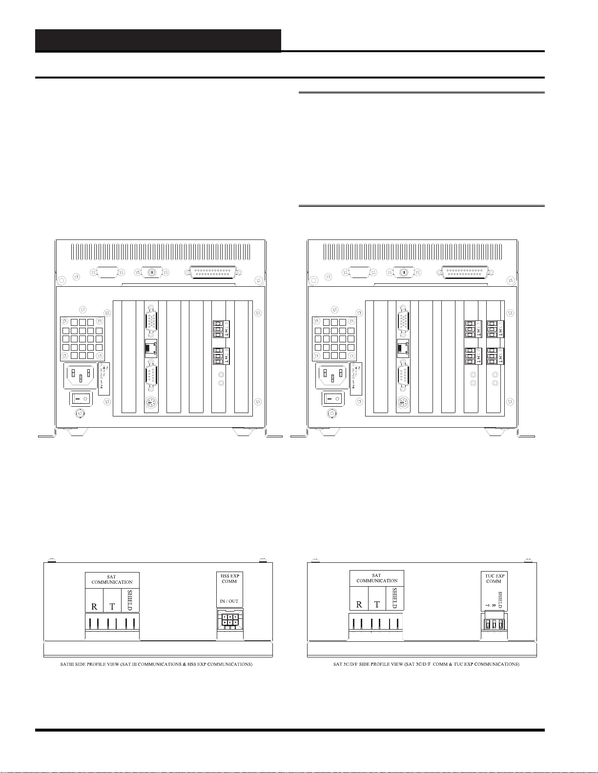
REAR PROFILE VIEW WCC I II - MCD (STANDARD WITH TWO SAT III COMMUNICATIONS CONNECTI ONS) REAR PROFILE VIEW WCC II I - MCD (WITH OPTIONAL TWO MORE SAT III COMMUNICATIONS CONNE CTIONS)
SA T 3C/D/F TUC Loop Communications
The SAT 3C/D/F TUC Loop
Communications
The software that is in the “old” existing TUC Controllers that
were connected to the “old” SAT 2c/d Controllers does not need
to be changed. WattMaster Controls decided to use the same
communications protocol to ease the replacement of the SA T 2C/D
controllers. Do not connect this loop to the SAT III “network”
communications loop as communication-related problems will
result.
PLEASE NOTE: Normally, all of the RS-485 wiring is
wired “R ” to “R,” “T” to “T, ” and “SHLD” to “SHLD” or
“SH.” This method of connection works for the wiring from
TUC Controller to TUC Controller. But, on the SA T 3C/D/F
Controller, the wire from the TUC “R” connection must
be wired to the SA T 3C/D/F “T” connection, and the SAT
3C/D/F Controller “R” connection must be wired to the TUC
“T” connecti on.
Figure 10-1: Rear Views of the WCC III – MCD showing SAT III RS-485 Communication Connections
Figure 10-2: Profi le of SAT III and SAT 3C/D/F showing the SAT III and TUC RS-485 Communication Connections
10-2
WCC III Technical Guide
Page 5
10. RS-485 COMMUNICATIONS
<<<LOCAL LOOP>>> AZWR-LL-WG-18>>> E76191 CL2P 18AWG (UL) 012112 FT
<<<NETWORK LOOP>>> AZWR-NL-WR-18>>> E76191 CL2P 18AWG (UL) 012112 FT
WATTMASTER LOCAL LOOP WIRE
WATTMASTER NETWORK LOOP WIRE
RS-485 Wire & P ower and Switchable RS-485 Communications Board
RS-485 Wire Considerations
The RS-485 wire specifi cations are generally a stranded 18-
gauge, 2-wire twisted pair with shield. 18-gauge stranded wire is
mandatory to ensure a good connection with the ¼-inch Sta-Con
connectors which are used to terminate the wires at the WCC III MCD and at the satellite controllers.
The old SAT II Manchester communications loop was supposed to
have used a 2-wire twisted pair with shield, but this was not used
in every installation. This old SAT II communications loop should
not be used for the new SAT III communications loop. A new RS485 communications loop should be run to each new replacement
SAT III Controller. The shield wire must be used on the new SAT
III Controller as it provides a “ground” reference for the RS-485
communication loop.
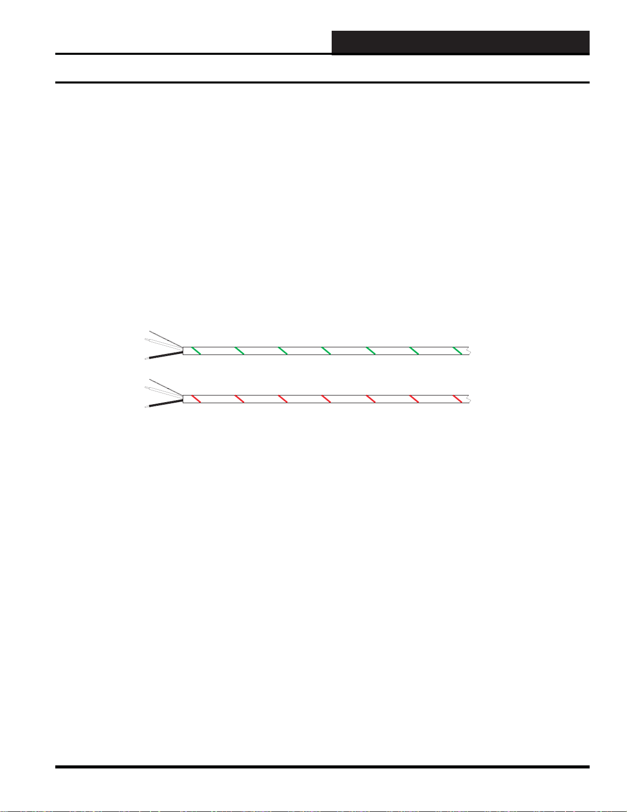
W attMaster Controls sells two versions of 18-gauge, 2-wire twisted
pair with shield communications wire:
• W attMaster part #WR-NL-WR-18 - marked “Network
Loop” with a red stripe for rapid identifi cation. This
wire should be run from the WCC III - MCD to the
SAT III, SAT 3C/D/F, SAT 3P, and then to the next
SAT 3-type controllers.
• W attMaster part #WR-LL-WG-18 - marked “Local
Loop” with a green stripe for rapid identifi cation for the
TUC loops that run from the SAT 3C/D/F controllers to
the TUC controllers.
Figure 10-3: WattMaster Controls various communications loop wire
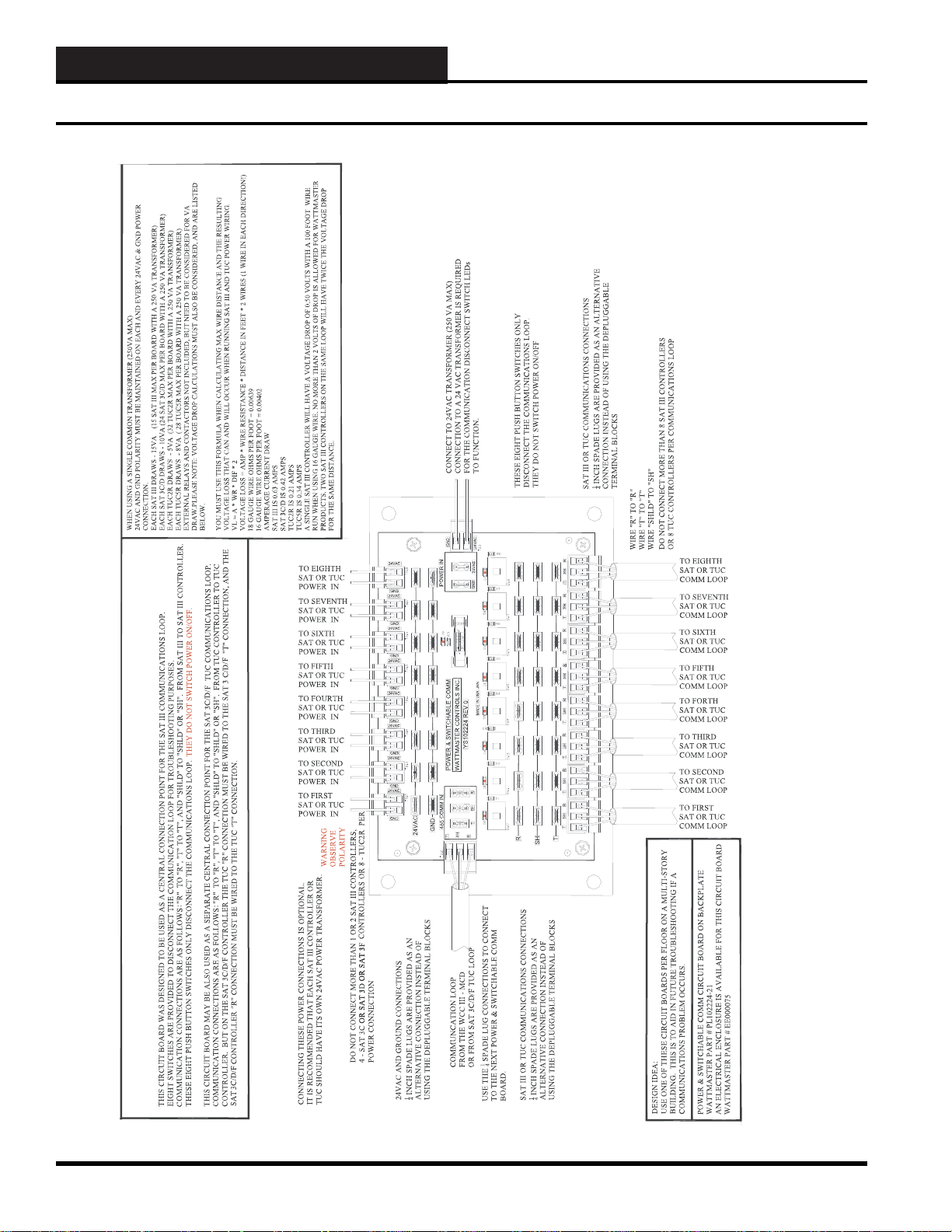
Power and Switc hable RS-485
Communications Board
“Wire Nuts” on the RS-485 communications loop should be avoided
at all costs. As an alternative to the “Wire Nuts”, WattMaster
Controls has a Power and Switchable RS-485 Communications
Board - WattMaster part #PL102224. The Power and Switchable
RS-485 Communications Board can be thought of as a 24-VAC
power and communication distribution system for the SAT III
communications loop that will aid in initial startup and future
troubleshooting of the SAT III communications loop. The Power
and Switch Boards should be used on a fl oor-by-fl oor basis. The
board is sold alone or in a small metal electrical enclosure. See
Figure 10-4.
This circuit board was designed to be used as a central connection
point for the SAT III communications loop. The eight switches are
provided only to disconnect the RS-485 communications loop for
troubleshooting purposes.
Wiring for the communication connections are as follows: “R”
to “R,” “T” to “T,” and “SHLD” to “SHLD” or “SH.” Connect
the wiring from the SAT III to a SAT III, SAT 3C/D/F, or SAT 3P
Controller. These eight push-button switches only disconnect the
communications loop. THEY DO NOT SWITCH POWER ON/
OFF .
This circuit board may be also used as a separate central connection
point for the SAT 3C/D/F - TUC communications loop.
Wiring for the communications connections are as follows: “R” to
“R,” “T” to “T,” and “SHLD” to “SHLD” or “SH.” Connect the
wiring from TUC controller to TUC controller. But on the SAT
3C/D/F controller, the TUC “R” connection must be wired to the
SAT 3C/D/F “T” connection, and the SAT 3C/D/F controller “R”
connection must be wired to the TUC “T” connection.
WCC III Technical Guide
10-3
Page 6
10. RS-485 COMMUNICATIONS
Pow er and Switchable RS-485 Communications Board
10-4
Figure 10-4: Power and Switchable RS-485 Communications Board Application Drawing
WCC III Technical Guide
Page 7

10. RS-485 COMMUNICATIONS
24V AC Pow er Wiring
24V AC P o wer Wiring Considerations
You do not have to use the 24VAC connections on the Power
and Switchable RS-485 Communications Board, as each SAT
III panel should have its own 120VAC-to-24VAC transformer.
However, WattMaster Controls included the 24VAC connections
on the Power and Switchable RS-485 Communications Board as a
convenience option for 24VAC power distribution wiring.
When using the Power and Switchable RS-485 Communications
Board with a common 24VAC (250VA MAX) transformer,
the24VAC and GND polarity must be maintained on each and
every 24VAC & GND power connection.
• Each SAT III draws - 15VA (No more than 15
SAT III max per board with a 250 VA - 24 VAC
transformer)
• Each SAT 3C/D/F draws - 10VA (No more than
24 SAT 3C/D/F max per board with a 250 VA - 24
VAC transformer)
• Each TUC-2R draws - 5VA (No more than 32
TUC-2R max per board with a 250 VA - 24 VAC
transformer)
WIRE RESISTANCE STANDARDS
• 18-Gauge WIRE OHMS PER FOOT = 0.00639
• 16-Gauge WIRE OHMS PER FOOT = 0.00402
AMPERAGE CURRENT DRAW for WattMaster Controls
products
• SAT III controller is 0.63 AMPS
• SAT 3C/D/F controller is 0.42 AMPS
• TUC-2R controller is 0.21 AMPS with actuator
• TUC5-R controller is 0.34 AMPS
Example 1:
A single SAT III controller will have a voltage drop of 0.50 volts
with 100 feet of wire run when using 16-gauge wire. No more than
2 volts of drop is allowed for any WattMaster product. Two SAT
III controllers on the same loop will have twice the voltage drop
for the same distance.
0.506 Volts of loss = “0.63” x “0.00402” x “100 feet” x “2”
• Each TUC-5R draws - 8VA (No more than 28
TUC-R max per board with a 250 VA - 24 VAC
transformer)
• External relays and contactors are not included, but
need to be considered for total VA draw.
PLEASE NOTE: Vol tage loss in wire calculations must also
be considered and are listed below .
You must use the formula below when calculating max wire
distance and the resulting voltage loss that can and will occur
when running SAT III and TUC power wiring.
The formula is as follows: “VL” = “A” x “WR” x “DIF” x “2”
VL = Voltage Loss, A = AMP Draw , WR = Wire Resistance, DIF =
Distance In Feet, 2 = 2 Wires (1 Wire in each direction!)
Example 2:
A single TUC-2R controller will have a voltage drop of 0.671 volts
with 250 feet of wire run when using 18-gauge wire. No more than
2 volts of drop is allowed for any WattMaster product. Two TUC2R controllers on the same loop will have twice the voltage drop
for the same distance.
0.671 Volts of loss = “0.21” x “0.00639” x “250 feet” x “2”
Example 3:
A single SAT 3C/D/F controller will have a voltage drop of 1.69
volts with 500 feet of wire run when using 16-gauge wire. No
more than 2 volts of drop is allowed for any WattMaster product.
Two SAT III controllers on the same loop will have twice the
voltage drop for the same distance.
1.689 Volts of loss = “0.42” x “0.00402” x “500 feet” x “2”
WCC III Technical Guide
10-5
Page 8
10. RS-485 COMMUNICATIONS
8
7
SATADDRESS
2
1
4
8
A3WIREROOMSENSORWILLNOT
REQUIREALOADRESISTORWHENSET
FORA1VOLTINPUT.
WattMasterControlsInc.
BINARY
INPUTS
BINARY
INPUTS
L8
ONOFF
128
32
16
64
L4
L3
L2
L1
L6
L5
L7
L11
L12
ONOFF
L10
L9
ONOFF
L15
L16
L14
L13
CH
4
3
5
6
2
1
LOCALSET
STATUS2
STATUS3
STATUS1
HSSXMIT
LOCALSET
LOCALSETDISABLE
BATTON/OFF
PULSEINPUT
OPTION1
TEST
OPTION3
OPTION2
ONOFF
STATUS
HSSREC
SATXMIT
SATREC
ANALOGINPUT
JUMPERSELECTION
A2WIREROOMSENSORWILLREQUIRE
A300OHMLOADRESISTORWHENSET
FORA1VOLTINPUT.
A4TO20mASENSORWILLREQUIREA
50OHMLOADRESISTORWHENSETFOR
A1VOLTINPUT,ORA250OHMLOAD
RESISTORWHENSETFORA5VOLTINPUT.
CURRENT
INPUT
THERMISTOR
INPUT
0-1V
0-5V
0-10V
THERM
0-1V
0-5V
0-10V
THERM
0TO10V
INPUT
0TO5V
INPUT
0TO1V
INPUT
0-10V
0-1V
0-5V
0-10V
THERM
0-1V
0-5V
THERM
0-1V
0-5V
0-10V
THERM
PROGRAMMABLECONTROLLER
SATIII
100VA
TRANSFORMER
SWITCH
DISCONNECT
INTERPANEL
100VA
TRANSFORMER
SWITCH
DISCONNECT
INTERPANEL
D
8
7
SATADDRESS
2
1
4
8
A3WIREROOMSENSORWILLNOT
REQUIREALOADRESISTORWHENSET
FORA1VOLTINPUT.
WattMasterControlsInc.
BINARY
INPUTS
BINARY
INPUTS
L8
ONOFF
128
32
16
64
L4
L3
L2
L1
L6
L5
L7
L11
L12
ONOFF
L10
L9
ONOFF
L15
L16
L14
L13
CH
4
3
5
6
2
1
LOCALSET
STATUS2
STATUS3
STATUS1
HSSXMIT
LOCALSET
LOCALSETDISABLE
BATTON/OFF
PULSEINPUT
OPTION1
TEST
OPTION3
OPTION2
ONOFF
STATUS
HSSREC
SATXMIT
SATREC
ANALOGINPUT
JUMPERSELECTION
A2WIREROOMSENSORWILLREQUIRE
A300OHMLOADRESISTORWHENSET
FORA1VOLTINPUT.
A4TO20mASENSORWILLREQUIREA
50OHMLOADRESISTORWHENSETFOR
A1VOLTINPUT,ORA250OHMLOAD
RESISTORWHENSETFORA5VOLTINPUT.
CURRENT
INPUT
THERMISTOR
INPUT
0-1V
0-5V
0-10V
THERM
0-1V
0-5V
0-10V
THERM
0TO10V
INPUT
0TO5V
INPUT
0TO1V
INPUT
0-10V
0-1V
0-5V
0-10V
THERM
0-1V
0-5V
THERM
0-1V
0-5V
0-10V
THERM
PROGRAMMABLECONTROLLER
SATIII
100VA
TRANSFORMER
SWITCH
DISCONNECT
INTERPANEL
100VA
TRANSFORMER
SWITCH
DISCONNECT
INTERPANEL
D
100VA
TRANSFORMER
SWITCH
DISCONNECT
INTERPANEL
D
8
7
SATADDRESS
2
1
4
8
A3WIREROOMSENSORWILLNOT
REQUIREALOADRESISTORWHENSET
FORA1VOLTINPUT.
WattMasterControlsInc.
BINARY
INPUTS
BINARY
INPUTS
L8
ONOFF
128
32
16
64
L4
L3
L2
L1
L6
L5
L7
L11
L12
ONOFF
L10
L9
ONOFF
L15
L16
L14
L13
CH
4
3
5
6
2
1
LOCALSET
STATUS2
STATUS3
STATUS1
HSSXMIT
LOCALSET
LOCALSETDISABLE
BATTON/OFF
PULSEINPUT
OPTION1
TEST
OPTION3
OPTION2
ONOFF
STATUS
HSSREC
SATXMIT
SATREC
ANALOGINPUT
JUMPERSELECTION
A2WIREROOMSENSORWILLREQUIRE
A300OHMLOADRESISTORWHENSET
FORA1VOLTINPUT.
A4TO20mASENSORWILLREQUIREA
50OHMLOADRESISTORWHENSETFOR
A1VOLTINPUT,ORA250OHMLOAD
RESISTORWHENSETFORA5VOLTINPUT.
CURRENT
INPUT
THERMISTOR
INPUT
0-1V
0-5V
0-10V
THERM
0-1V
0-5V
0-10V
THERM
0TO10V
INPUT
0TO5V
INPUT
0TO1V
INPUT
0-10V
0-1V
0-5V
0-10V
THERM
0-1V
0-5V
THERM
0-1V
0-5V
0-10V
THERM
PROGRAMMABLECONTROLLER
SATIII
100VA
TRANSFORMER
SWITCH
DISCONNECT
INTERPANEL
BASEMENT
1st Floor
2nd Floor
8
7
SATADDRESS
2
1
4
8
A3WIREROOMSENSORWILLNOT
REQUIREALOADRESISTORWHENSET
FORA1VOLTINPUT.
WattMasterControlsInc.
BINARY
INPUTS
BINARY
INPUTS
L8
ONOFF
128
32
16
64
L4
L3
L2
L1
L6
L5
L7
L11
L12
ONOFF
L10
L9
ONOFF
L15
L16
L14
L13
CH
4
3
5
6
2
1
LOCALSET
STATUS2
STATUS3
STATUS1
HSSXMIT
LOCALSET
LOCALSETDISABLE
BATTON/OFF
PULSEINPUT
OPTION1
TEST
OPTION3
OPTION2
ONOFF
STATUS
HSSREC
SATXMIT
SATREC
ANALOGINPUT
JUMPERSELECTION
A2WIREROOMSENSORWILLREQUIRE
A300OHMLOADRESISTORWHENSET
FORA1VOLTINPUT.
A4TO20mASENSORWILLREQUIREA
50OHMLOADRESISTORWHENSETFOR
A1VOLTINPUT,ORA250OHMLOAD
RESISTORWHENSETFORA5VOLTINPUT.
CURRENT
INPUT
THERMISTOR
INPUT
0-1V
0-5V
0-10V
THERM
0-1V
0-5V
0-10V
THERM
0TO10V
INPUT
0TO5V
INPUT
0TO1V
INPUT
0-10V
0-1V
0-5V
0-10V
THERM
0-1V
0-5V
THERM
0-1V
0-5V
0-10V
THERM
PROGRAMMABLECONTROLLER
SATIII
100VA
TRANSFORMER
SWITCH
DISCONNECT
8
7
SATADDRESS
2
1
4
8
A3WIREROOMSENSORWILLNOT
REQUIREALOADRESISTORWHENSET
FORA1VOLTINPUT.
WattMasterControlsInc.
BINARY
INPUTS
BINARY
INPUTS
L8
ONOFF
128
32
16
64
L4
L3
L2
L1
L6
L5
L7
L11
L12
ONOFF
L10
L9
ONOFF
L15
L16
L14
L13
CH
4
3
5
6
2
1
LOCALSET
STATUS2
STATUS3
STATUS1
HSSXMIT
LOCALSET
LOCALSETDISABLE
BATTON/OFF
PULSEINPUT
OPTION1
TEST
OPTION3
OPTION2
ONOFF
STATUS
HSSREC
SATXMIT
SATREC
ANALOGINPUT
JUMPERSELECTION
A2WIREROOMSENSORWILLREQUIRE
A300OHMLOADRESISTORWHENSET
FORA1VOLTINPUT.
A4TO20mASENSORWILLREQUIREA
50OHMLOADRESISTORWHENSETFOR
A1VOLTINPUT,ORA250OHMLOAD
RESISTORWHENSETFORA5VOLTINPUT.
CURRENT
INPUT
THERMISTOR
INPUT
0-1V
0-5V
0-10V
THERM
0-1V
0-5V
0-10V
THERM
0TO10V
INPUT
0TO5V
INPUT
0TO1V
INPUT
0-10V
0-1V
0-5V
0-10V
THERM
0-1V
0-5V
THERM
0-1V
0-5V
0-10V
THERM
PROGRAMMABLECONTROLLER
SATIII
INTERPANEL
100VA
TRANSFORMER
8
7
SATADDRESS
2
1
4
8
A3WIREROOMSENSORWILLNOT
REQUIREALOADRESISTORWHENSET
FORA1VOLTINPUT.
WattMasterControlsInc.
BINARY
INPUTS
BINARY
INPUTS
L8
ONOFF
128
32
16
64
L4
L3
L2
L1
L6
L5
L7
L11
L12
ONOFF
L10
L9
ONOFF
L15
L16
L14
L13
CH
4
3
5
6
2
1
LOCALSET
STATUS2
STATUS3
STATUS1
HSSXMIT
LOCALSET
LOCALSETDISABLE
BATTON/OFF
PULSEINPUT
OPTION1
TEST
OPTION3
OPTION2
ONOFF
STATUS
HSSREC
SATXMIT
SATREC
ANALOGINPUT
JUMPERSELECTION
A2WIREROOMSENSORWILLREQUIRE
A300OHMLOADRESISTORWHENSET
FORA1VOLTINPUT.
A4TO20mASENSORWILLREQUIREA
50OHMLOADRESISTORWHENSETFOR
A1VOLTINPUT,ORA250OHMLOAD
RESISTORWHENSETFORA5VOLTINPUT.
CURRENT
INPUT
THERMISTOR
INPUT
0-1V
0-5V
0-10V
THERM
0-1V
0-5V
0-10V
THERM
0TO10V
INPUT
0TO5V
INPUT
0TO1V
INPUT
0-10V
0-1V
0-5V
0-10V
THERM
0-1V
0-5V
THERM
0-1V
0-5V
0-10V
THERM
PROGRAMMABLECONTROLLER
SATIII
100VA
TRANSFORMER
SWITCH
DISCONNECT
INTERPANEL
8
7
SATADDRESS
2
1
4
8
A3WIREROOMSENSORWILLNOT
REQUIREALOADRESISTORWHENSET
FORA1VOLTINPUT.
WattMasterControlsInc.
BINARY
INPUTS
BINARY
INPUTS
L8
ONOFF
128
32
16
64
L4
L3
L2
L1
L6
L5
L7
L11
L12
ONOFF
L10
L9
ONOFF
L15
L16
L14
L13
CH
4
3
5
6
2
1
LOCALSET
STATUS2
STATUS3
STATUS1
HSSXMIT
LOCALSET
LOCALSETDISABLE
BATTON/OFF
PULSEINPUT
OPTION1
TEST
OPTION3
OPTION2
ONOFF
STATUS
HSSREC
SATXMIT
SATREC
ANALOGINPUT
JUMPERSELECTION
A2WIREROOMSENSORWILLREQUIRE
A300OHMLOADRESISTORWHENSET
FORA1VOLTINPUT.
A4TO20mASENSORWILLREQUIREA
50OHMLOADRESISTORWHENSETFOR
A1VOLTINPUT,ORA250OHMLOAD
RESISTORWHENSETFORA5VOLTINPUT.
CURRENT
INPUT
THERMISTOR
INPUT
0-1V
0-5V
0-10V
THERM
0-1V
0-5V
0-10V
THERM
0TO10V
INPUT
0TO5V
INPUT
0TO1V
INPUT
0-10V
0-1V
0-5V
0-10V
THERM
0-1V
0-5V
THERM
0-1V
0-5V
0-10V
THERM
PROGRAMMABLECONTROLLER
SATIII
100VA
TRANSFORMER
SWITCH
DISCONNECT
INTERPANEL
3rd Floor
8
7
SATADDRESS
2
1
4
8
A3WIREROOMSENSORWILLNOT
REQUIREALOADRESISTORWHENSET
FORA1VOLTINPUT.
WattMasterControlsInc.
BINARY
INPUTS
BINARY
INPUTS
L8
ONOFF
128
32
16
64
L4
L3
L2
L1
L6
L5
L7
L11
L12
ONOFF
L10
L9
ONOFF
L15
L16
L14
L13
CH
4
3
5
6
2
1
LOCALSET
STATUS2
STATUS3
STATUS1
HSSXMIT
LOCALSET
LOCALSETDISABLE
BATTON/OFF
PULSEINPUT
OPTION1
TEST
OPTION3
OPTION2
ONOFF
STATUS
HSSREC
SATXMIT
SATREC
ANALOGINPUT
JUMPERSELECTION
A2WIREROOMSENSORWILLREQUIRE
A300OHMLOADRESISTORWHENSET
FORA1VOLTINPUT.
A4TO20mASENSORWILLREQUIREA
50OHMLOADRESISTORWHENSETFOR
A1VOLTINPUT,ORA250OHMLOAD
RESISTORWHENSETFORA5VOLTINPUT.
CURRENT
INPUT
THERMISTOR
INPUT
0-1V
0-5V
0-10V
THERM
0-1V
0-5V
0-10V
THERM
0TO10V
INPUT
0TO5V
INPUT
0TO1V
INPUT
0-10V
0-1V
0-5V
0-10V
THERM
0-1V
0-5V
THERM
0-1V
0-5V
0-10V
THERM
PROGRAMMABLECONTROLLER
SATIII
100VA
TRANSFORMER
SWITCH
DISCONNECT
INTERPANEL
100VA
TRANSFORMER
SWITCH
DISCONNECT
INTERPANEL
D
100VA
TRANSFORMER
SWITCH
DISCONNECT
INTERPANEL
D
4th Floor
4X4
HANDY BOX
WIRE
NUTS
WIRE
NUTS
TO
WCCIII - MCD
SAT III IN A ENCLOSURESAT3D INAENCLOSURE
2 - SAT III I N A DUAL ENCLOSURE
SAT III IN A ENCLOSURESAT3D INAENCLOSURE
SAT III IN A ENCLOSURESAT3D INAENCLOSURE
SAT III IN A ENCLOSURE
SAT III IN A ENCLOSURESAT3D INAENCLOSURESAT3D IN A ENCLOSURE
SAT III IN A ENCL OSURESAT III IN A ENCLOSURE
SAT 3D IN A ENCL OSURE
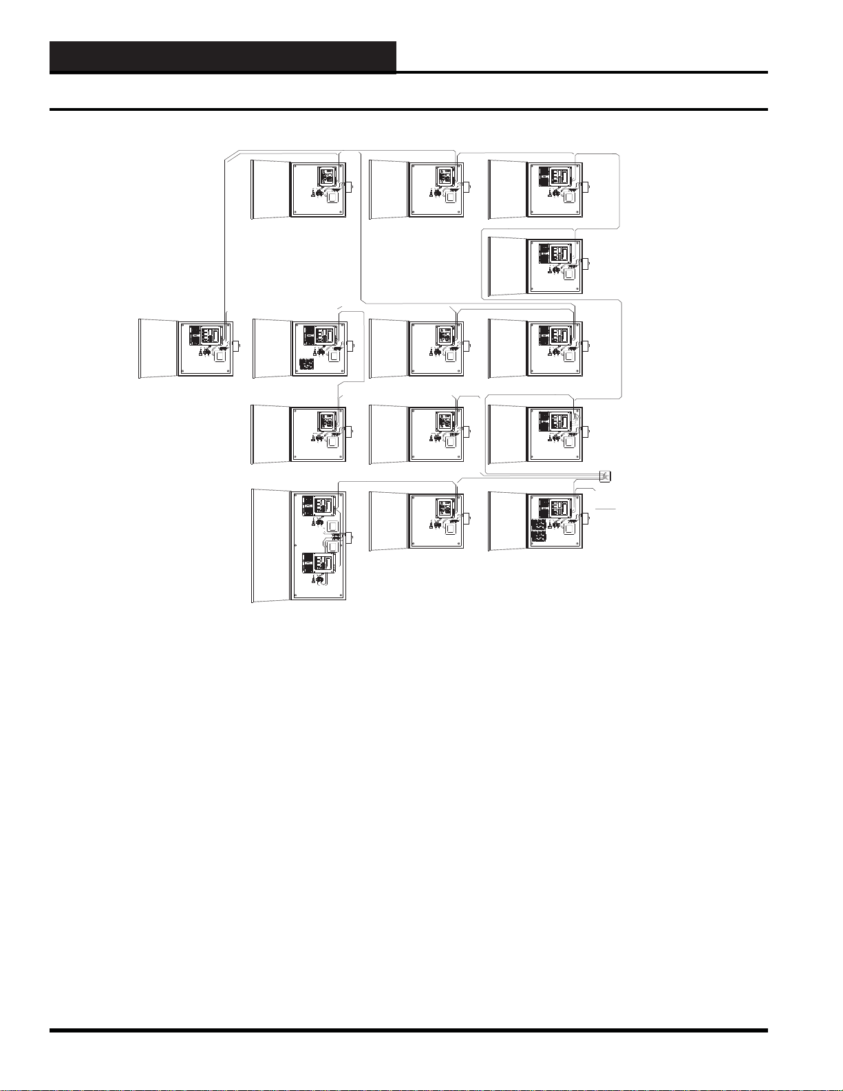
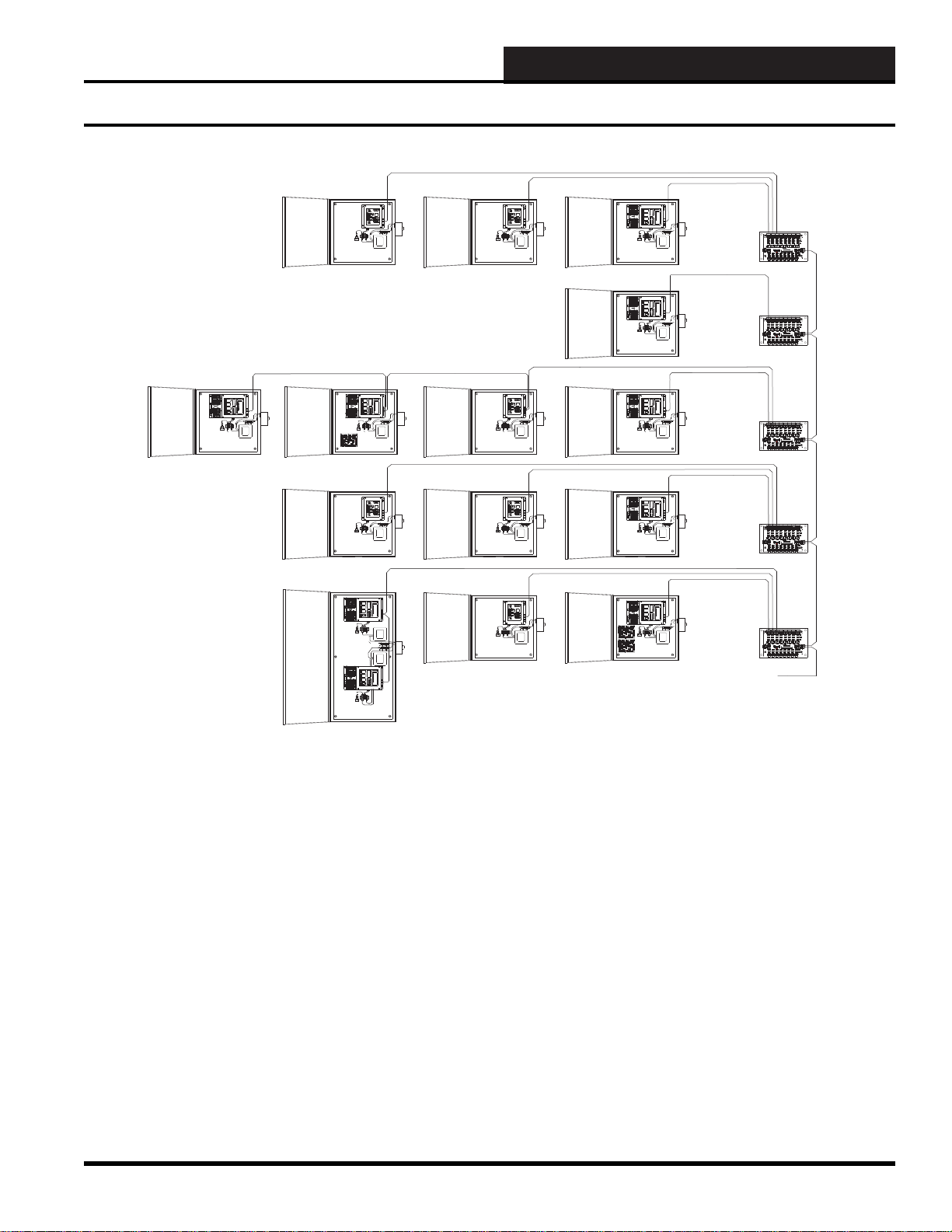
Wrong Communications Wiring
Figure 10-5: Typical WCC III System Communications Wiring – Not the recommended and preferred way
Wiring of the WCC III RS-485 communications loop as represented
in Figure 10-5 is not recommend for the following reasons:
1. The use of “Wire Nuts” to connect the communications wire at
a central hub (the 4x4 handy box) and inside of a SA T III enclosure
is not a good idea. The connections will oxidize over time and the
resistance of the “Wire-Nutted” connections will increase over
time. Generally speaking, the use of “Wire Nuts” can and will
cause a problem with the WCC III communication loop at some
point. Also, tugging or pulling on the WCC III communications
wiring during troubleshooting or during routine maintenance can
and generally will cause these “Wire Nuts” connections to break
apart.
10-6
2. The haphazard way the WCC III communications wiring was
run in Figure 10-5 is also not recommended. In this example,
wiring was run from the 2nd fl oor to the 4th fl oor and then back
to the 2nd fl oor and then back to the 4th fl oor again. The WCC III
communications wiring should make sense and never jump fl oors
or go back down a fl oor and then go back up a fl oor. See Figure
10-6 which shows a diagram of how the WCC III communications
wiring should be run and to use for troubleshooting purposes.
3. A Power and Switchable RS-485 communication board
(PL102224) was not used on a fl oor-by-fl oor basis. Use of this
board will aid in initial startup and in future troubleshooting.
WCC III Technical Guide
Page 9
10. RS-485 COMMUNICATIONS
8
7
SATADDRESS21
4
8
A3WIREROOMSENSORWILLNOT
REQUIREALOADRESISTORWHENSET
FORA1VOLTINPUT.
WattMasterControlsInc.
BINARY
INPUTS
BINARY
INPUTS
L8
ONOFF
128
32
16
64
L4
L3
L2
L1
L6
L5
L7
L11
L12
ONOFF
L10
L9
ONOFF
L15
L16
L14
L13
CH
4
3
5
6
2
1
LOCALSET
STATUS2
STATUS3
STATUS1
HSSXMIT
LOCALSET
LOCALSETDISABLE
BATTON/OFF
PULSEINPUT
OPTION1
TEST
OPTION3
OPTION2
ONOFF
STATUS
HSSREC
SATXMIT
SATREC
ANALOGINPUT
JUMPERSELECTION
A2WIREROOMSENSORWILLREQUIRE
A300OHMLOADRESISTORWHENSET
FORA1VOLTINPUT.
A4TO20mASENSORWILLREQUIREA
50OHMLOADRESISTORWHENSETFOR
A1VOLTINPUT,ORA250OHMLOAD
RESISTORWHENSETFORA5VOLTINPUT.
CURRENT
INPUT
THERMISTOR
INPUT
0-1V
0-5V
0-10V
THERM
0-1V
0-5V
0-10V
THERM
0TO10V
INPUT
0TO5V
INPUT
0TO1V
INPUT
0-10V
0-1V
0-5V
0-10V
THERM
0-1V
0-5V
THERM
0-1V
0-5V
0-10V
THERM
PROGRAMMABLECONTROLLER
SATIII
100VA
TRANSFORMER
SWITCH
DISCONNECT
INTERPANEL
100VA
TRANSFORMER
SWITCH
DISCONNECT
INTERPANEL
D
8
7
SATADDRESS
2
1
4
8
A3WIREROOMSENSORWILLNOT
REQUIREALOADRESISTORWHENSET
FORA1VOLTINPUT.
WattMasterControlsInc.
BINARY
INPUTS
BINARY
INPUTS
L8
ONOFF
128
32
16
64
L4
L3
L2
L1
L6
L5
L7
L11
L12
ONOFF
L10
L9
ONOFF
L15
L16
L14
L13
CH
4
3
5
6
2
1
LOCALSET
STATUS2
STATUS3
STATUS1
HSSXMIT
LOCALSET
LOCALSETDISABLE
BATTON/OFF
PULSEINPUT
OPTION1
TEST
OPTION3
OPTION2
ONOFF
STATUS
HSSREC
SATXMIT
SATREC
ANALOGINPUT
JUMPERSELECTION
A2WIREROOMSENSORWILLREQUIRE
A300OHMLOADRESISTORWHENSET
FORA1VOLTINPUT.
A4TO20mASENSORWILLREQUIREA
50OHMLOADRESISTORWHENSETFOR
A1VOLTINPUT,ORA250OHMLOAD
RESISTORWHENSETFORA5VOLTINPUT.
CURRENT
INPUT
THERMISTOR
INPUT
0-1V
0-5V
0-10V
THERM
0-1V
0-5V
0-10V
THERM
0TO10V
INPUT
0TO5V
INPUT
0TO1V
INPUT
0-10V
0-1V
0-5V
0-10V
THERM
0-1V
0-5V
THERM
0-1V
0-5V
0-10V
THERM
PROGRAMMABLECONTROLLER
SATIII
100VA
TRANSFORMER
SWITCH
DISCONNECT
INTERPANEL
100VA
TRANSFORMER
SWITCH
DISCONNECT
INTERPANEL
D
100VA
TRANSFORMER
SWITCH
DISCONNECT
INTERPANEL
D
8
7
SATADDRESS
2
1
4
8
A3WIREROOMSENSORWILLNOT
REQUIREALOADRESISTORWHENSET
FORA1VOLTINPUT.
WattMasterControlsInc.
BINARY
INPUTS
BINARY
INPUTS
L8
ONOFF
128
32
16
64
L4
L3
L2
L1
L6
L5
L7
L11
L12
ONOFF
L10
L9
ONOFF
L15
L16
L14
L13
CH
4
3
5
6
2
1
LOCALSET
STATUS2
STATUS3
STATUS1
HSSXMIT
LOCALSET
LOCALSETDISABLE
BATTON/OFF
PULSEINPUT
OPTION1
TEST
OPTION3
OPTION2
ONOFF
STATUS
HSSREC
SATXMIT
SATREC
ANALOGINPUT
JUMPERSELECTION
A2WIREROOMSENSORWILLREQUIRE
A300OHMLOADRESISTORWHENSET
FORA1VOLTINPUT.
A4TO20mASENSORWILLREQUIREA
50OHMLOADRESISTORWHENSETFOR
A1VOLTINPUT,ORA250OHMLOAD
RESISTORWHENSETFORA5VOLTINPUT.
CURRENT
INPUT
THERMISTOR
INPUT
0-1V
0-5V
0-10V
THERM
0-1V
0-5V
0-10V
THERM
0TO10V
INPUT
0TO5V
INPUT
0TO1V
INPUT
0-10V
0-1V
0-5V
0-10V
THERM
0-1V
0-5V
THERM
0-1V
0-5V
0-10V
THERM
PROGRAMMABLE CONTROLLER
SATIII
100VA
TRANSFORMER
SWITCH
DISCONNECT
INTERPANEL
BASEMENT
1st Floor
2nd Floor
8
7
SATADDRESS21
4
8
A3WIREROOMSENSORWILLNOT
REQUIREALOADRESISTORWHENSET
FORA1VOLTINPUT.
WattMasterControlsInc.
BINARY
INPUTS
BINARY
INPUTS
L8
ONOFF
128
32
16
64
L4
L3
L2
L1
L6
L5
L7
L11
L12
ONOFF
L10
L9
ONOFF
L15
L16
L14
L13
CH
4
3
5
6
2
1
LOCALSET
STATUS2
STATUS3
STATUS1
HSSXMIT
LOCALSET
LOCALSETDISABLE
BATTON/OFF
PULSEINPUT
OPTION1
TEST
OPTION3
OPTION2
ONOFF
STATUS
HSSREC
SATXMIT
SATREC
ANALOGINPUT
JUMPERSELECTION
A2WIREROOMSENSORWILLREQUIRE
A300OHMLOADRESISTORWHENSET
FORA1VOLTINPUT.
A4TO20mASENSORWILLREQUIREA
50OHMLOADRESISTORWHENSET FOR
A1VOLTINPUT,ORA250OHMLOAD
RESISTORWHENSETFORA5VOLTINPUT.
CURRENT
INPUT
THERMISTOR
INPUT
0-1V
0-5V
0-10V
THERM
0-1V
0-5V
0-10V
THERM
0TO10V
INPUT
0TO5V
INPUT
0TO1V
INPUT
0-10V
0-1V
0-5V
0-10V
THERM
0-1V
0-5V
THERM
0-1V
0-5V
0-10V
THERM
PROGRAMMABLECONTROLLER
SATIII
100VA
TRANSFORMER
SWITCH
DISCONNECT
8
7
SATADDRESS
2
1
4
8
A3WIREROOMSENSORWILLNOT
REQUIREALOADRESISTORWHENSET
FORA1VOLTINPUT.
WattMasterControlsInc.
BINARY
INPUTS
BINARY
INPUTS
L8
ONOFF
128
32
16
64
L4
L3
L2
L1
L6
L5
L7
L11
L12
ONOFF
L10
L9
ONOFF
L15
L16
L14
L13
CH
4
3
5
6
2
1
LOCALSET
STATUS2
STATUS3
STATUS1
HSSXMIT
LOCALSET
LOCALSETDISABLE
BATTON/OFF
PULSEINPUT
OPTION1
TEST
OPTION3
OPTION2
ONOFF
STATUS
HSSREC
SATXMIT
SATREC
ANALOGINPUT
JUMPERSELECTION
A2WIREROOMSENSORWILLREQUIRE
A300OHMLOADRESISTORWHENSET
FORA1VOLTINPUT.
A4TO20mASENSORWILLREQUIREA
50OHMLOADRESISTORWHENSET FOR
A1VOLTINPUT,ORA250OHMLOAD
RESISTORWHENSETFORA5VOLTINPUT.
CURRENT
INPUT
THERMISTOR
INPUT
0-1V
0-5V
0-10V
THERM
0-1V
0-5V
0-10V
THERM
0TO10V
INPUT
0TO5V
INPUT
0TO1V
INPUT
0-10V
0-1V
0-5V
0-10V
THERM
0-1V
0-5V
THERM
0-1V
0-5V
0-10V
THERM
PROGRAMMABLECONTROLLER
SATIII
INTERPANEL
100VA
TRANSFORMER
8
7
SATADDRESS
2
1
4
8
A3WIREROOMSENSORWILLNOT
REQUIREALOADRESISTORWHENSET
FORA1VOLTINPUT.
WattMasterControlsInc.
BINARY
INPUTS
BINARY
INPUTS
L8
ONOFF
128
32
16
64
L4
L3
L2
L1
L6
L5
L7
L11
L12
ONOFF
L10
L9
ONOFF
L15
L16
L14
L13
CH
4
3
5
6
2
1
LOCALSET
STATUS2
STATUS3
STATUS1
HSSXMIT
LOCALSET
LOCALSETDISABLE
BATTON/OFF
PULSEINPUT
OPTION1
TEST
OPTION3
OPTION2
ONOFF
STATUS
HSSREC
SATXMIT
SATREC
ANALOGINPUT
JUMPERSELECTION
A2WIREROOMSENSORWILLREQUIRE
A300OHMLOADRESISTORWHENSET
FORA1VOLTINPUT.
A4TO20mASENSORWILLREQUIREA
50OHMLOADRESISTORW HE NSETFOR
A1VOLTINPUT,ORA250OHMLOAD
RESISTORWHENSETFORA5VOLTINPUT.
CURRENT
INPUT
THERMISTOR
INPUT
0-1V
0-5V
0-10V
THERM
0-1V
0-5V
0-10V
THERM
0TO10V
INPUT
0TO5V
INPUT
0TO1V
INPUT
0-10V
0-1V
0-5V
0-10V
THERM
0-1V
0-5V
THERM
0-1V
0-5V
0-10V
THERM
PROGRAMMABLECONTROLLER
SATIII
100VA
TRANSFORMER
SWITCH
DISCONNECT
INTERPANEL
8
7
SATADDRESS21
4
8
A3WIREROOMSENSORWILLNOT
REQUIREALOADRESISTORWHENSET
FORA1VOLTINPUT.
WattMasterControlsInc.
BINARY
INPUTS
BINARY
INPUTS
L8
ONOFF
128
32
16
64
L4
L3
L2
L1
L6
L5
L7
L11
L12
ONOFF
L10
L9
ONOFF
L15
L16
L14
L13
CH
4
3
5
6
2
1
LOCALSET
STATUS2
STATUS3
STATUS1
HSSXMIT
LOCALSET
LOCALSETDISABLE
BATTON/OFF
PULSEINPUT
OPTION1
TEST
OPTION3
OPTION2
ONOFF
STATUS
HSSREC
SATXMIT
SATREC
ANALOGINPUT
JUMPERSELECTION
A2WIREROOMSENSORWILLREQUIRE
A300OHMLOADRESISTORWHENSET
FORA1VOLTINPUT.
A4TO20mASENSORWILLREQUIREA
50OHMLOADRESISTORWHENSETFOR
A1VOLTINPUT,ORA250OHMLOAD
RESISTORWHENSETFORA5VOLTINPUT.
CURRENT
INPUT
THERMISTOR
INPUT
0-1V
0-5V
0-10V
THERM
0-1V
0-5V
0-10V
THERM
0TO10V
INPUT
0TO5V
INPUT
0TO1V
INPUT
0-10V
0-1V
0-5V
0-10V
THERM
0-1V
0-5V
THERM
0-1V
0-5V
0-10V
THERM
PROGRAMMABLECONTROLLER
SATIII
100VA
TRANSFORMER
SWITCH
DISCONNECT
INTERPANEL
3rd Floor
8
7
SATADDRESS
2
1
4
8
A3WIREROOMSENSORWILLNOT
REQUIREALOADRESISTORWHENSET
FORA1VOLTINPUT.
WattMasterControlsInc.
BINARY
INPUTS
BINARY
INPUTS
L8
ONOFF
128
32
16
64
L4
L3
L2
L1
L6
L5
L7
L11
L12
ONOFF
L10
L9
ONOFF
L15
L16
L14
L13
CH
4
3
5
6
2
1
LOCALSET
STATUS2
STATUS3
STATUS1
HSSXMIT
LOCALSET
LOCALSETDISABLE
BATTON/OFF
PULSEINPUT
OPTION1
TEST
OPTION3
OPTION2
ONOFF
STATUS
HSSREC
SATXMIT
SATREC
ANALOGINPUT
JUMPERSELECTION
A2WIREROOMSENSORWILLREQUIRE
A300OHMLOADRESISTORWHENSET
FORA1VOLTINPUT.
A4TO20mASENSORWILLREQUIREA
50OHMLOADRESISTORWHENSETFOR
A1VOLTINPUT,ORA250OHMLOAD
RESISTORWHENSETFORA5VOLTINPUT.
CURRENT
INPUT
THERMISTOR
INPUT
0-1V
0-5V
0-10V
THERM
0-1V
0-5V
0-10V
THERM
0TO10V
INPUT
0TO5V
INPUT
0TO1V
INPUT
0-10V
0-1V
0-5V
0-10V
THERM
0-1V
0-5V
THERM
0-1V
0-5V
0-10V
THERM
PROGRAMMABLECONTROLLER
SATIII
100VA
TRANSFORMER
SWITCH
DISCONNECT
INTERPANEL
100VA
TRANSFORMER
SWITCH
DISCONNECT
INTERPANEL
D
100VA
TRANSFORMER
SWITCH
DISCONNECT
INTERPANEL
D
4th Floor
GND
24VAC
GND
24VAC
24VAC
24VAC
24VAC
24VAC
24VAC
24VAC
24VAC
GND
GND
GND
GND
GND
GND
GND
24VAC
GND
24VAC
GND
485COMMIN
POWERIN
POWER&SWITCHABLECOMM
WATTMASTERCONTROLSINC.
YS102224REV0
MADEINUSAJRN
T
R
SH
TSHR
R
SH
T
TSHRTSHRTSHRTSHRTSHR TSHRTSHRTSHR
GND
24VAC
GND
24VAC
24VAC
24VAC
24VAC
24VAC
24VAC
24VAC
24VAC
GND
GND
GND
GND
GND
GND
GND
24VACGND
24VAC
GND
485COMMIN POWERIN
POWER&SWITCHABLECOMM
WATTMASTERCONTROLSINC.
YS102224REV0
MADEINUSAJRN
T
R
SH
TSHR
R
SH
T
TSHRTSHRTSHRTSHRTSHR TSHRTSHRTSHR
GND
24VAC
GND
24VAC
24VAC
24VAC
24VAC
24VAC
24VAC
24VAC
24VAC
GND
GND
GND
GND
GND
GND
GND
24VACGND
24VAC
GND
485COMMIN
POWERIN
POWER&SWITCHABLECOMM
WATTMASTERCONTROLSINC.
YS102224REV0
MADEINUSAJRN
T
R
SH
TSHR
R
SH
T
TSHRTSHRTSHRTSHRTSHR TSHRTSHRTSHR
GND
24VAC
GND
24VAC
24VAC
24VAC
24VAC
24VAC
24VAC
24VAC
24VAC
GND
GND
GND
GND
GND
GND
GND
24VACGND
24VAC
GND
485COMMIN
POWERIN
POWER&SWITCHABLECOMM
WATTMASTERCONTROLSINC.
YS102224REV0
MADEINUSAJRN
T
R
SH
TSHR
R
SH
T
TSHRTSHRTSHRTSHRTSHR TSHRTSHRTSHR
GND
24VAC
GND
24VAC
24VAC
24VAC
24VAC
24VAC
24VAC
24VAC
24VAC
GND
GND
GND
GND
GND
GND
GND
24VACGND
24VAC
GND
485COMMIN
POWERIN
POWER&SWITCHABLECOMM
WATTMASTERCONTROLSINC.
YS102224REV0
MADEINUSAJRN
T
R
SH
TSHR
R
SH
T
TSHRTSHRTSHRTSHRTSHR TSHRTSHRTSHR
TO
WCCIII - MCD
SATIIIINAENCLOSURESAT 3D IN A ENCL OSURE
2-SATIIIINADUALENCLOSURE
SATIIIINAENCLOSURESAT 3D IN A ENCL OSURE
SATIIIINAENCLOSURESAT 3D IN A ENCL OSURE
SATIIIINAENCLOSURE
SATIIIINAENCLOSURESAT 3D IN A ENCL OSURESAT 3D IN A ENC LOSURE
SAT III IN A ENCLOSURESAT III IN A ENCLOSURE
SAT 3D IN A ENCL OSURE
POWER & SWITCHABLE
COMMBOARD (PL102224)
POWER & SWITCHABLE
COMMBOARD (PL102224)
POWER & SWITCHABLE
COMMBOARD (PL102224)
POWER & SWITCHABLE
COMMBOARD (PL102224)
POWER & SWITCHABLE
COMMBOARD (PL102224)
Recommended Communications Wiring
Figure 10-6: Typical WCC III System Communications Wiring – The recommended and preferred way
Wiring of the WCC III RS-485 communications loop as represented
in Figure 10-6 is recommended for the following reasons:
1. “Wire Nuts” were not used.
2. The way the WCC III communications wiring was run is also
recommended. Making a main WCC III communications trunk
line and wiring from the basement to the 1st fl oor, then to the 2nd
fl oor, then 3rd fl oor, and then to the 4th fl oor, makes logical sense.
The location of the WCC III - MCD is not shown, but it could be
3. A Power and Switchable RS-485 Communication Board
(PL102224) was used on a fl oor-by-fl oor basis. Use of this board
will aid in initial startup and in future troubleshooting. This Power
and Switchable RS-485 Communication Board (PL102224) has
push buttons on each of the 8 communications connections going
out from it. You can connect as many SAT III / SAT 3C/D/F
controllers as you wish to each switchable connection, but
remember that you can only isolate down to that loop of X number
of SAT III controllers.
anywhere in the building as long as it is connected to the main
trunk line. Also, lighting protection devices should be added on
every fl oor as a preventive measure.
WCC III Technical Guide
10-7
Page 10

10. RS-485 COMMUNICATIONS
Lightning Suppression
Lightning Suppression
Lightning is an act of nature and as such cannot be predicted or
controlled. There is NOTHING that will COMPLETELY protect
any electronic equipment from the massive effects of a direct or
near hit from lightning. WattMaster Controls has taken a number
of steps to protect the electronic components and the incoming
pathways of its equipment from voltage surges that may enter
them. These incoming pathways are defi ned as: 24VAC power,
RS-232 data communications, RS-485 data communications, input
wiring, and relay control circuits. All of these pathways have been
protected using a variety of devices, including varistors, diodes,
transorbs, and excessive ground planes on all of our circuit boards.
There are several “General Rules” that can be applied towards
lightning protection:
General Rule Number One: Any time the WCC III /Satellite
RS-485 communication’s loop enters or leaves a building, there
needs to be a properly installed and grounded lightning protection
device or lightning suppressor device.
General Rule Number Two: No lightning protection devices
or lightning suppressor devices will protect against a direct
lightning hit.
At some point you have to ask the question: “What
exactly are you trying to protect?”
Lightning could enter the building via an analog input on a TUC-2R,
and then it could cause problems with the RS-485 communications
loop on the SAT 3C/D/F TUC communications loop along with
more problems on the SAT RS-485 communications loop. You
could have your entire building’s control system go down due to a
close lightning strike. The most likely path that lightning would take
to do the most damage would be on the RS-485 communications
loop that connects the Satellite controllers to each other. You may
decide to put multiple lightning protection devices or lightning
suppressor devices on every RS-485 communications loop as a
preventive safety measure.
WattMaster Controls sells an RS-485 communications loop
lightning protection device. The WattMaster part number is
OE437-03.
General Rule Number Three: For a lightning protection
device or lightning suppressor device to work properly, there needs
to be an actual earth-ground connection point as near as possible
to the lightning protection device or lightning suppressor device.
Being feet away from the actual earth-ground connection does not
work, Being inches away is always the best possible connection
point for this actual ground connection.
10-8
WCC III Technical Guide
Page 11

10. RS-485 COMMUNICATIONS
MCD Troubleshooting with a Digital V oltmeter
MCD Communications T roubleshooting with a Digital Voltmeter
Troubleshooting of the WCC III system RS-485 satellite communications loop is possible with a digital voltmeter.
Figure 10-7: Typical WCC III - MCD RS-485 Satellite Communications DC V oltage Measurements with the Loop
Connected
The voltage measurements in Figure 10-7 are approximate voltages. These voltage measurements are taken when the power to the
WCC III - MCD is “ON” and the RS-485 communications loop is connected. These two voltages will fl uctuate slightly and also will
momentarily “fl ip” to the other meter reading’s value. The voltage measurement from “T” to “SHIELD” should be around 2.7 VDC. The
voltage measurement from “R” to “SHIELD” should be around 3.00 VDC. Typical bad voltage measurement values would be anything
above 3.8 VDC and anything below 1.5 VDC. This voltage measurement applies to both top and bottom RS-485 loop communications
connections.
Figure 10-8: Typical WCC III - MCD RS-485 Satellite Communications DC V oltage Measurements with the Loop
Disconnected
The voltage measurements in Figure 10-8 are approximate voltages. These voltage measurements are taken when the power to the
WCC III - MCD is “ON” and the RS-485 communications loop is disconnected. These two voltages will fl uctuate slightly and also will
momentarily “fl ip” to the other meter reading’s value. The voltage measurement from “T” to “SHIELD” should be around 2.7 VDC. The
voltage measurement from “R” to “SHIELD” should be around 3.00 VDC. Typical bad voltage measurement values would be anything
above 3.8 VDC and anything below 1.5 VDC. This voltage measurement applies to both top and bottom RS-485 loop communications
connections.
WCC III Technical Guide
10-9
Page 12

10. RS-485 COMMUNICATIONS
SA T III Troubleshooting with a Digital V oltmeter
SA T III Communications T roubleshooting with a Digital Voltmeter
Figure 10-9: Typical SAT III RS-485 Sa tellite Communications DC Voltage Measurements with the Loop
Connected
The voltage measurements in Figure 10-9 are approximate voltages. These voltage measurements are taken when the power to the SAT
III Controller is “ON” and the RS-485 SAT communications loop is connected. These two voltages will fl uctuate slightly and also will
momentarily “fl ip” to the other meter reading’s value. The voltage measurement from “T” to “SHIELD” should be around 2.7 VDC. The
voltage measurement from “R” to “SHIELD” should be around 3.00 VDC. Typical bad voltage measurement values would be anything
above 3.8 VDC and anything below 1.5 VDC. Helpful hint: Removal of the SAT III cover may aid in measuring the communication loop
voltages.
Figure 10-10: Typical SAT III RS-485 Sa tellite Communications DC Voltage Measurements with the Loop
Disconnected
The voltage measurements in Figure 10-10 are approximate voltages. These voltage measurements are taken when the power to the SAT
III Controller is “ON” and the RS-485 SAT communications loop is disconnected. These two voltages will not fl uctuate. The voltage
measurement from “T” to “SHIELD” should be around 3.25 VDC. The voltage measurement from “R” to “SHIELD” should be around
3.25 VDC. Typical bad voltage measurement values would be anything above 3.8 VDC and anything below 1.5 VDC. Helpful hint:
Removal of the SAT III cover may aid in measuring the communication loop voltages.
10-10
WCC III Technical Guide
Page 13

10. RS-485 COMMUNICATIONS
SA T 3C/D/F Troubleshooting with a Digital V oltmeter
SA T 3C/D/F Communications T roubleshooting with a Digital Voltmeter
Figure 10-11: Typical SAT 3C/D/F RS-485 Sa tellite Communications DC Voltage Measurements with the SAT
COMM Loop Connected
The voltage measurements in Figure 10-1 1 are approximate voltages. These voltage measurements are taken when the power to the SAT
3C/D/F Controller is “ON” and the RS-485 SA T communications loop is connected. These two voltages will fl uctuate slightly and also will
momentarily “fl ip” to the other meter reading’s value. The voltage measurement from “T” to “SHIELD” should be around 2.7 VDC. The
voltage measurement from “R” to “SHIELD” should be around 3.00 VDC. Typical bad voltage measurement values would be anything
above 3.8 VDC and anything below 1.5 VDC. Helpful hint: Removal of the SAT 3C/D/F cover may aid in measuring the communication
loop voltages.
Figure 10-12: Typical SAT 3C/D/F RS-485 Sa tellite Communications DC Voltage Measurements with the SAT
COMM Loop Disconnected
The voltage measurements in Figure 10-12 are approximate voltages. These voltage measurements are taken when the power to the SAT
3C/D/F controller is “ON” and the RS-485 SAT communications loop is disconnected. These two voltages will not fl uctuate. The voltage
measurement from “T” to “SHIELD” should be around 3.25 VDC. The voltage measurement from “R” to “SHIELD” should be around
3.25 VDC. Typical bad voltage measurement values would be anything above 3.8 VDC and anything below 1.5 VDC. Helpful hint:
Removal of the SAT 3C/D/F cover may aid in measuring the communication loop voltages.
WCC III Technical Guide
10-11
Page 14

10. RS-485 COMMUNICATIONS
SA T 3C/D/F Troubleshooting with a Digital V oltmeter
Figure 10-13: Typical SAT 3C/D/F TUC RS-485 Sa tellite Communications DC Voltage Measurements with the
TUC COMM Loop Connected
The voltage measurements in Figure 10-13 are approximate voltages. These voltage measurements are taken when the power to the SAT
3C/D/F Controller is “ON” and the RS-485 TUC EXP communications loop is connected. These two voltages will fl uctuate slightly and
also will momentarily “fl ip” to the other meter reading’s value. The voltage measurement from “T” to “SHIELD” should be around 2.7
VDC. The voltage measurement from “R” to “SHIELD” should be around 3.00 VDC. Typical bad voltage measurement values would
be anything above 3.8 VDC and anything below 1.5 VDC. Helpful hint: Removal of the SAT 3C/D/F cover may aid in measuring the
communication loop voltages.
Figure 10-14: Typical SAT 3C/D/F TUC RS-485 Sa tellite Communications DC Voltage Measurements with the
TUC COMM Loop Disconnected
The voltage measurements in Figure 10-14 are approximate voltages. These voltage measurements are taken when the power to the SAT
3C/D/F Controller is “ON” and the RS-485 TUC EXP communications loop is disconnected. These two voltages will not fl uctuate. The
voltage measurement from “T” to “SHIELD” should be around 3.25 VDC. The voltage measurement from “R” to “SHIELD” should be
around 3.25 VDC. T ypical bad voltage measurement values would be anything above 3.8 VDC and anything below 1.5 VDC. Helpful hint:
Removal of the SAT 3C/D/F cover may aid in measuring the communication loop voltages.
10-12
WCC III Technical Guide
Page 15

10. RS-485 COMMUNICATIONS
SA T 3P Troubleshooting with a Digital V oltmeter
Figure 10-15: Typical SAT 3P TUC RS-485 Sa tellite Communications DC Voltage Measurements with the SAT
COMM Loop Connected
The voltage measurements in Figure 10-15 are approximate voltages. All SAT 3P controllers should use the LT1785 driver chip. These
voltages are taken when the SAT 3P controller is “ON” and the RS-485 SAT communications loop is connected. These two voltages will
fl uctuate slightly and also will momentarily “fl ip” to the other meter reading’s value. The voltage measurements from “T” to “SHLD” should
be around 2.70 VDC. The voltage measurements from “R” to “SHLD” should be around 3.00 VDC. Typical bad voltages measurements
values would be anything above 3.8 VDC and anything below 1.5 VDC.
Figure 10-16: Typical SAT 3P TUC RS-485 Sa tellite Communications DC Voltage Measurements with the SAT
COMM Loop Disconnected
The voltage measurements in Figure 10-16 are approximate voltages. All SAT 3P controllers should use the LT1785 driver chip. These
voltages are taken when the SAT 3P controller is “ON” and the RS-485 SAT communications loop is disconnected. These two voltages
will not fl uctuate. The voltage measurements from “T” to “SHLD” should be around 3.25 VDC. The voltage measurements from “R” to
“SHLD” should be around 3.25 VDC. Typical bad voltages measurements values would be anything above 3.8 VDC and anything below
1.5 VDC.
WCC III Technical Guide
10-13
Page 16

10. RS-485 COMMUNICATIONS
TUC-2R Troubleshooting with a Digital V oltmeter
TUC-2R Communications T roubleshooting with a Digital Voltmeter
Figure 10-17: Typical TUC-2R RS-485 TUC Communications DC Voltage Measurements with the TUC COMM
Loop Disconnected – LT1785 Driv er
The voltage measurements in Figure 10-17 are approximate voltages. Newer TUC-2R Controllers use a different RS-485 driver chip.
These voltage measurements are taken when the power to the TUC-2R Controller is “ON” and the RS-485 TUC communications loop is
disconnected. These two voltages will not fl uctuate. The voltage measurement from “T” to “SHIELD” should be around 3.25 VDC. The
voltage measurement from “R” to “SHIELD” should be around 3.25 VDC. Typical bad voltage measurement values would be anything
above 3.8 VDC and anything below 1.5 VDC.
Figure 10-18: Typical TUC-2R RS-485 TUC Communications DC Voltage Measurements with the TUC COMM
Loop Disconnected – 75176 Driver
The voltage measurements in Figure 10-18 are approximate voltages. Older TUC-2R Controllers used a different RS-485 driver chip.
These voltage measurements are taken when the power to the TUC-2R Controller is “ON” and the RS-485 TUC communications loop is
disconnected. These two voltages will not fl uctuate. The voltage measurement from “T” to “SHIELD” should be around 2.50 VDC. The
voltage measurement from “R” to “SHIELD” should be around 2.50 VDC. Typical bad voltage measurement values would be anything
above 3.8 VDC and anything below 1.5 VDC.
10-14
WCC III Technical Guide
Page 17

10. RS-485 COMMUNICATIONS
TUC-2R Troubleshooting with a Digital V oltmeter
Figure 10-19: Typical TUC-2R RS-485 TUC Communications DC Voltage Measurements with the TUC COMM
Loop Connected – LT1785 Driv er
The voltage measurements in Figure 10-19 are approximate voltages. These voltages are taken when the TUC2R controller is “ON” and
the RS-485 TUC communications loop is connected. These two voltages will fl uctuate slightly and also will momentarily “fl ip” to the
other meter reading’s value. The voltage measurements from “T” to “SHLD” should be around 2.70 VDC. The voltage measurements
from “R” to “SHLD” should be around 3.00 VDC. Typical bad voltage measurement values would be anything above 3.8 VDC and
anything below 1.5 VDC.
Figure 10-20: Typical TUC-2R RS-485 TUC Communications DC Voltage Measurements with the TUC COMM
Loop Connected – 75176 Driver
The voltage measurements in Figure 10-20 are approximate voltages. These voltages are taken when the TUC2R controller is “ON” and
the RS-485 TUC communications loop is connected. These two voltages will fl uctuate slightly and also will momentarily “fl ip” to the
other meter reading’s value. The voltage measurements from “T” to “SHLD” should be around 2.70 VDC. The voltage measurements
from “R” to “SHLD” should be around 3.00 VDC. Typical bad voltage measurement values would be anything above 3.8 VDC and
anything below 1.5 VDC.
WCC III Technical Guide
10-15
Page 18

10. RS-485 COMMUNICATIONS
V AVZ II T roubleshooting with a Digital Voltmeter
Figure 10-21: Typical VAVZ II RS-485 TUC Communications DC Voltage Measurements with the TUC COMM
Loop Connected – LT1785 Driv er
The voltage measurements in Figure 10-21 are approximate voltages. All VAVZ II controllers should use the LT1785 driver chip. These
voltages are taken when the VAVZ II controller is “ON” and the RS-485 TUC communications loop is connected. These two voltages will
fl uctuate slightly and also will momentarily “fl ip” to the other meter reading’s value. The voltage measurements from “T” to “SHLD” should
be around 2.70 VDC. The voltage measurements from “R” to “SHLD” should be around 3.00 VDC. Typical bad voltages measurements
values would be anything above 3.8 VDC and anything below 1.5 VDC.
Figure 10-22: Typical VAVZ II RS-485 TUC Communications DC Voltage Measurements with the TUC COMM
Loop Disconnected – LT1785 Driv er
The voltage measurements in Figure 10-22 are approximate voltages. All VAVZ II controllers should use the LT1785 driver chip. These
voltages are taken when the VAVZ II controller is “ON” and the RS-485 TUC communications loop is disconnected. These two voltages
will not fl uctuate. The voltage measurements from “T” to “SHLD” should be around 3.25 VDC. The voltage measurements from “R” to
“SHLD” should be around 3.25 VDC. Typical bad voltages measurements values would be anything above 3.8 VDC and anything below
1.5 VDC.
10-16
WCC III Technical Guide
Page 19

10. RS-485 COMMUNICATIONS
TUC-5R Troubleshooting with a Digital V oltmeter
TUC-5R Communications T roubleshooting with a Digital Voltmeter
Figure 10-23: Typical TUC-5R RS-485 TUC Communications DC Voltage Measurements with the TUC COMM
Loop Disconnected – 75176 Driver
The voltage measurements in Figure 10-23 are approximate voltages. Older TUC-5R Controllers used a different RS-485 driver chip.
These voltage measurements are taken when the power to the TUC-5R Controller is “ON” and the RS-485 TUC communications loop is
disconnected. These two voltages will not fl uctuate. The voltage measurement from “T” to “SHIELD” should be around 2.50 VDC. The
voltage measurement from “R” to “SHIELD” should be around 2.50 VDC. Typical bad voltage measurement values would be anything
above 3.8 VDC and anything below 1.5 VDC.
Figure 10-24: Typical TUC-5R RS-485 TUC Communications DC Voltage Measurements with the TUC COMM
Loop Disconnected – LT1785 Driv er
The voltage measurements in Figure 10-24 are approximate voltages. Older TUC-5R Controllers used a different RS-485 driver chip.
These voltage measurements are taken when the power to the TUC-5R Controller is “ON” and the RS-485 TUC communications loop is
disconnected. These two voltages will not fl uctuate. The voltage measurement from “T” to “SHIELD” should be around 3.25 VDC. The
voltage measurement from “R” to “SHIELD” should be around 3.25 VDC. Typical bad voltage measurement values would be anything
above 3.8 VDC and anything below 1.5 VDC.
WCC III Technical Guide
10-17
Page 20

10. RS-485 COMMUNICATIONS
TUC-5R Troubleshooting with a Digital V oltmeter
Figure 10-25: Typical TUC-5R RS-485 TUC Communications DC Voltage Measurements with the TUC COMM
Loop Connected – 75176 Driver
The voltage measurements in Figure 10-25 are approximate voltages. Older TUC-5R Controllers used a different RS-485 driver chip.
These voltages are taken when the TUC5R controller is “ON” and the RS-485 TUC communications loop is connected. These two
voltages will fl uctuate slightly and also will momentarily “fl ip” to the other meter reading’ s value. The voltage measurements from “T” to
“SHLD” should be around 2.70 VDC. The voltage measurements from “R” to “SHLD” should be around 3.00 VDC. T ypical bad voltages
measurements values would be anything above 3.8 VDC and anything below 1.5 VDC.
Figure 10-26: Typical TUC-5R RS-485 TUC Communications DC Voltage Measurements with the TUC COMM
Loop Connected – LT1785 Driv er
The voltage measurements in Figure 10-26 are approximate voltages. Older TUC-5R Controllers used a different RS-485 driver chip.
These voltages are taken when the TUC5R controller is “ON” and the RS-485 TUC communications loop is connected. These two
voltages will fl uctuate slightly and also will momentarily “fl ip” to the other meter reading’ s value. The voltage measurements from “T” to
“SHLD” should be around 2.70 VDC. The voltage measurements from “R” to “SHLD” should be around 3.00 VDC. T ypical bad voltages
measurements values would be anything above 3.8 VDC and anything below 1.5 VDC.
10-18
WCC III Technical Guide
Page 21

10. RS-485 COMMUNICATIONS
RTU-17 T roubleshooting with a Digital Voltmeter
RTU-17 Communications T roubleshooting with a Digital Voltmeter
Figure 10-27: Typical RTU-17 RS-485 TUC Communications DC V oltage Measurements with the TUC COMM
Loop Disconnected – 75176 Driver
The voltage measurements in Figure 10-27 are approximate voltages. Older RTU-17 Controllers used a different RS-485 driver chip.
These voltage measurements are taken when the power to the TUC-5R Controller is “ON” and the RS-485 TUC communications loop is
disconnected. These two voltages will not fl uctuate. The voltage measurement from “T” to “SHIELD” should be around 2.50 VDC. The
voltage measurement from “R” to “SHIELD” should be around 2.50 VDC. Typical bad voltage measurement values would be anything
above 3.8 VDC and anything below 1.5 VDC.
Figure 10-28: Typical RTU-17 RS-485 TUC Communications DC V oltage Measurements with the TUC COMM
Loop Disconnected – LT1785 Driv er
The voltage measurements in Figure 10-28 are approximate voltages. Older RTU-17 Controllers used a different RS-485 driver chip.
These voltage measurements are taken when the power to the RTU-17 Controller is “ON” and the RS-485 TUC communications loop is
disconnected. These two voltages will not fl uctuate. The voltage measurement from “T” to “SHIELD” should be around 3.25 VDC. The
voltage measurement from “R” to “SHIELD” should be around 3.25 VDC. Typical bad voltage measurement values would be anything
above 3.8 VDC and anything below 1.5 VDC.
WCC III Technical Guide
10-19
Page 22

10. RS-485 COMMUNICATIONS
RTU-17 T roubleshooting with a Digital Voltmeter
Figure 10-29: Typical RTU-17 RS-485 TUC Communications DC V oltage Measurements with the TUC COMM
Loop Connected – 75176 Driver
The voltage measurements in Figure 10-29 are approximate voltages. Older RTU-17 Controllers used a different RS-485 driver chip.
These voltages are taken when the RTU-17 controller is “ON” and the RS-485 TUC communications loop is connected. These two
voltages will fl uctuate slightly and also will momentarily “fl ip” to the other meter reading’ s value. The voltage measurements from “T” to
“SHLD” should be around 2.70 VDC. The voltage measurements from “R” to “SHLD” should be around 3.00 VDC. T ypical bad voltages
measurements values would be anything above 3.8 VDC and anything below 1.5 VDC.
Figure 10-30: Typical RTU-17 RS-485 TUC Communications DC V oltage Measurements with the TUC COMM
Loop Connected – LT1785 Driv er
The voltage measurements in Figure 10-30 are approximate voltages. Older RTU-17 Controllers used a different RS-485 driver chip.
These voltages are taken when the RTU-17 controller is “ON” and the RS-485 TUC communications loop is connected. These two
voltages will fl uctuate slightly and also will momentarily “fl ip” to the other meter reading’ s value. The voltage measurements from “T” to
“SHLD” should be around 2.70 VDC. The voltage measurements from “R” to “SHLD” should be around 3.00 VDC. T ypical bad voltages
measurements values would be anything above 3.8 VDC and anything below 1.5 VDC.
10-20
WCC III Technical Guide
Page 23

10. RS-485 COMMUNICATIONS
Global Bridge Troubleshooting with a Digital V oltmeter
Global Bridge Communications T roubleshooting with a Digital Voltmeter
Figure 10-31: Typical Global Bridge RS-485 TUC Communications DC Voltage Measurements with the SAT
COMM Loop Connected
The voltage measurements in Figure 10-31 are approximate voltages. These voltage measurements are taken when the power to the
Global Bridge Controller is “ON” and the RS-485 SAT III communications loop is connected. These two voltages will fl uctuate slightly
and also will momentary “fl ip” to the other meter reading’s value. The voltage measurement from “T” to “SHIELD” should be around 2.7
VDC. The voltage measurement from “R” to “SHIELD” should be around 3.00 VDC. Typical bad voltage measurement values would be
anything above 3.8 VDC and anything below 1.5 VDC.
Figure 10-32: Typical Global Bridge RS-485 TUC Communications DC Voltage Measurements with the SAT
COMM Loop Disconnected
The voltage measurements in Figure 10-32 are approximate voltages. These voltage measurements are taken when the power to the
Global Bridge Controller is “ON” and the RS-485 SAT III communications loop is disconnected. These two voltages will not fl uctuate.
The voltage measurement from “T” to “SHIELD” should be around 3.25 VDC. The voltage measurement from “R” to “SHIELD” should
be around 3.25 VDC. Typical bad voltage measurement values would be anything above 3.8 VDC and anything below 1.5 VDC.
WCC III Technical Guide
10-21
Page 24

10. RS-485 COMMUNICATIONS
Replacing RS-485 Driv er Chip(s) on SAT III
Replacing RS-485 Driv er Chips
Y ou must fi rst disconnect the 24V AC power and then disconnect the three-wire RS-485 communications loop connections before you can
attempt to remove or replace a RS-485 communications driver chip. Failure to do so may result in a damaged driver chip and/or damaged
circuit board(s).
Figure 10-33: Replacing the RS-485 Driver Chip(s) on the SA T III Controller
10-22
WCC III Technical Guide
Page 25

10. RS-485 COMMUNICATIONS
Replacing RS-485 Driv er Chip(s) on SAT 3P and TUC-5R
Y ou must fi rst disconnect the 24V AC power and then disconnect the three-wire RS-485 communications loop connections before you can
attempt to remove or replace a RS-485 communications driver chip. Failure to do so may result in a damaged driver chip and/or damaged
circuit board(s).
Figure 10-34: Replacing the RS-485 Driver Chip(s) on the SA T 3P Controller
Figure 10-35: Replacing the RS-485 Driver Chip(s) on the TUC-5R / TUC-5R+ Controller
WCC III Technical Guide
10-23
Page 26

10. RS-485 COMMUNICATIONS
Replacing RS-485 Driv er Chips on RTU17, TUC-2R, and VA VZ II
Y ou must fi rst disconnect the 24V AC power and then disconnect the three-wire RS-485 communications loop connections before you can
attempt to remove or replace a RS-485 communications driver chip. Failure to do so may result in a damaged driver chip and/or damaged
circuit board(s).
Figure 10-36: Replacing the RS-485 Driver Chip(s) on the RTU-17 and TUC-2R Controller
Figure 10-37: Replacing the RS-485 Driver Chip(s) on the V AVZ II Controller
10-24
WCC III Technical Guide
Page 27

10. RS-485 COMMUNICATIONS
Replacing RS-485 Driv er Chips on Global Bridge
Figure 10-38: Replacing the RS-485 Driver Chip(s) on the Global Bridge Controller
WCC III Technical Guide
10-25
Page 28

10. RS-485 COMMUNICATIONS
Replacing RS-485 Driv er Chips on the SAT 3C/D/F
SAT C/D/F REV 3 TUC RS485 DRIVER
LOCATION "U16"
REPLACE THE 75176 CHIP WITH THE
LT1785 CHIP
74HC04
34063A
34063A
SAT 3C/D REV3 RS485 DRIVER LOCATION "U5"
THIS RS485 DRIVER IS FOR "SAT" COMM
REPLACE THE 75176 CHIP WITH THE
LT1785 CHIP
Figure 10-39: Replacing the RS-485 Driver Chip(s) on the SA T 3C/D/F
10-26
WCC III Technical Guide
Page 29

10. RS-485 COMMUNICATIONS
Replacing RS-485 Driv er Chips on the WCC3 Binary Input Board
WCC3 BINARYIN W/ TIME DELAY
WATTMASTER CONTROLS, INC
YS102072 REV 2
WCC3 BINARY INPUT
RS485 DRIVER LOCATION
REPLACE THE 75176 CHIP
WITH THE LT1785 CHIP
Figure 10-40: Replacing the RS-485 Driver Chip(s) on the WCC3 Binary Input Board
WCC III Technical Guide
10-27
Page 30

10. RS-485 COMMUNICATIONS
Replacing RS-485 Driv er Chips on the WCC3 V-Out R elay Board
OMRON
OMRON
OMRON
OMRON
OMRON
OMRON
OMRON
OMRON
G5Q-14
DC24V
SA
VDE
5A30VDC
CHINA
10A250VAC ~
G5Q-14
G5Q-14
DC24V
DC24V
5A30VDC
CHINA
10A250VAC ~
VDE
VDE
5A30VDC
CHINA
10A250VAC ~
G5Q-14
G5Q-14
DC24V
DC24V
5A30VDC
CHINA
10A250VAC ~
VDE
VDE
5A30VDC
CHINA
10A250VAC ~
G5Q-14
G5Q-14
DC24V
DC24V
VDE
5A30VDC
CHINA
CHINA
10A250VAC ~
SA
SA
SA
SA
SA
SA
5A30VDC
10A250VAC ~
SA
G5Q-14
DC24V
VDE
VDE
5A30VDC
CHINA
10A250VAC ~
V-OUT RELAY REV3 RS485
DRIVER LOCATION "U5"
REPLACE THE 75176 CHIP
WITH THE LT1785 CHIP
Figure 10-41: Replacing the RS-485 Driver Chip(s) on the WCC3 V -Out R elay Board
10-28
WCC III Technical Guide
 Loading...