

Page 1

13A. WCC III - MCD
Installation Guide
WCC III
13A. WCC III - MCD
Installation Guide
Page 2

T ABLE OF CONTENTS
SECTION 13A: WCC III - MCD
INST ALLA TION GUIDE
WCC III System Requirements ...............13A-1
The WCC III – MCD Basic Operating
Conditions ...............................................13A-2
Uninterruptable Power Supply ...............................13A-2
MCD (Master Communications Device) ................13A-2
Software Updates .................................................. 13A-2
WCC III – MCD Internet Access ..............13A-3
Wall Mounting of the WCC III – MCD .......13A-4
System Setup ..........................................13A-6
WCC III - MCD Display .............................13A-7
The WCC III – MCD ................................13A-15
Using the MCD-Menu Program ...........................13A-16
BIOS Screen Setup Information for the
Advantech SBC Model PCI-6881
(V1.20 & V1.21) .....................................13A-23
WCCIII – MCD Linux Base System
Install ...................................................13A-25
The WCC III System RS-485
Communication Wiring .........................13A-12
WCC III - MCD Typical System Architecture .......13A-13
Initiating the System ............................13A-14
MCD System Files ...............................................13A-14
Page 3

13. WCC III - MCD INSTALLATION GUIDE
System Requirements
SECTION 13A:
WCC III - MCD INST ALLA TION GUIDE
__________________________________________
WCC III System Requirements
To accomplish remote communications via the internet, the
following items are needed in addition to the WCC III system in
order to control the building mechanical systems. The WCC III
system is not to be used in any application where Fire/Life/Safety
is an issue.
WCC III – MCD System Requirements
(On-Site WCC III – MCD Computer):
• DSL or a Cable router/switch that connects to the
internet. Or, as an alternative, an internal jobsite
IP network that does not connect to the internet,
but when using this internal jobsite IP network, the
external internet Email of alarms from the WCC
III-MCD will not be possible. Also, external access
via the internet may not be possible. An ethernet
crossover cable is supplied for stand alone nonnetwork applications.
Front End Software Requirements
(Operator Console Software):
• A Microsoft Windows XP /Vista/Windows 7-based
computer.
• Minimum hardware specifi cation for the Microsoft
Windows XP / Vista based computer is a Pentium
IV running at 2.4 Giga Hertz with at least 1 GB
of RAM, and 10 GB of spare hard drive space. A
CDROM/DVD drive is also required for software
installation.
• WCC III software package – Provided on a
CDROM, or is available via a download on the
WCC Controls website: www.wcc-controls.com.
The installation CDROM contains the following
programs:
WCC III.exe (SS5021)
WCCUTILITY.exe (SS5023)
SCUSCR.exe (SS5026)
WCC3Trendlog.exe (SS5028)
TenantReport.exe (SS5025)
TenantOverride.exe* (SS5024)
WCC3Download.exe (SS5030)
WCC3Guest.exe (SS5022)
• A fi xed static IP address or a fi xed IP domain host
name from the ISP along with a provisioning sheet
that contains other pertinent IP setup information.
• Minimum hardware specifi cation for the Microsoft
Windows XP / Vista / 7 based computer is a
Pentium IV running at 2.4 Giga Hertz with at least
1 GB of RAM, and 10 GB of spare hard drive
space. A CDROM/DVD drive is also required for
software installation.
• Enabled port forwarding on the Firewall of the
router/switch. This is only if a fi rewall is used.
• An Email address that supports a SMTP
server for SENDING with a pop server for
RECEIVING Emails, and it must have “auth
login” authentication. TLS or SSL modes are not
supported. WattMaster Controls can provide an
Email address with these requirements.
• An Uninterruptible Power Supply (UPS) – 750-
Watt minimum
• A wall mounting surface is preferred.
• A dedicated 120VAC power circuit is required.
• WCC III Controls website: www.wcc-controls.com
• The CDROM part number (WattMaster Part #
DM1WC011-01X, were “X” = revision level)
• A DSL or Cable router/switch that connects to the
internet, or access to the internet via some other
method. Or, as an alternative, an internal jobsite
IP network that does not connect to the internet,
but when using this internal jobsite IP network, the
external internet Email of alarms from the WCC III
- MCD may not be possible.
* NOTE: The TenantOverride.exe program is also available
as a single program installation for the end users that are using
the simplistic graphical interface of the TenantOverride.exe
screen to locally turn on and off specifi c control points that are
applicable to the end user.
WCC III Technical Guide
13A-1
Page 4

13. WCC III - MCD INSTALLATION GUIDE
Basic Operating Conditions
The WCC III – MCD Basic Operating
Conditions
The WCC III - MCD must be kept in a clean and dry area in the
building. The ambient temperature must be between 50 and 100 °F,
and the relative humidity must be kept between 0 and 90% (noncondensing). The interior components are cooled by ventilation
fans within the WCC III – MCD unit, and therefore the unit should
not be kept in tightly confi ned or enclosed areas. The WCC III -
MCD is primarily designed to mount on a wall with the supplied
brackets.
The WCC III – MCD computer requires 115 VAC power and must
remain powered at all times for proper operation and control. The
115 VAC power circuit must be separate and dedicated exclusively
to the WCC III – MCD computer.
A dedicated Network IP Address or Domain Name is required.
Uninterruptable Power Supply
The WCC III - MCD system is designed to automatically restart
after a power failure. However, the industrial computer which
acts as the WCC III Master Communications Device will not
automatically reboot unless the power is shut off cleanly and
then restored cleanly. During most power outages, the incoming
115 AC voltage could have great fl uctuations before the power
fi nally fails. In a like manner, brownouts will usually cause the
industrial computer to “lock-up.” That is to say, the screen will
continue to display on the monitor, but the cursor will not respond
to the keyboard commands. To prevent this “lock-up” issue from
happening to the WCC III – MCD, an Uninterruptible Power
Supply (UPS) is required on each and every WCC III – MCD
computer.
An Uninterruptible Power Supply (UPS) provides emergency
power to keep the WCC III Master Communications Device
(personal computer) on-line for several minutes after a primary
power failure. The UPS regulates the incoming power to the
computer and shuts the power off cleanly several seconds after the
power outage, or brownout. When the primary power is restored,
the UPS brings the MCD back on-line automatically. The WCC
III system does not lose any information since all of the programs
and user entered data are stored on either a disk in the MCD, on
fi rmware, or on battery backed memory in the satellite controllers.
MCD (Master Communications
Device)
The MCD has the following specifi cations:
• A PCI Slot type Single Board Computer in a wall
mounted case
• Processor - Pentium M processor running at 1.3
Ghz
• Memory – 1 GB SODIMM
• Hard Drive – Solid State 8 GB Hard Drive.
• 2 line by 20 character Dot Matrix LCD display
• Backplane – A passive 5 slot PCI backplane
• Required I/O
1 - External RS232 port (9 Pin connector)
2 - External USB ports
2 - Internal USB ports
1 - Ethernet Port
Software Updates
WCC III-MCD program updates will be made available using
USB “jump” drives and/or internet uploading.
NOTE: As of September 1, 2009 all WCC III - MCDs will
only be shipped with the Linux operating system installed.
Older Windows XP-based WCC III - MCDs should be
upgraded for any future support issues from WattMaster.
The Windows XP operating system is at the end of long
term support with Microsoft. Microsoft’s main issues are
with continuous updates, and the multitude of viruses that
are written for Windows XP are also of concern. The Linux
operating system software on the WCC III - MCD must be
maintained and updated periodically. WattMaster Controls,
Inc. can do these software updates and upgrades remotely
via the internet only if the WCC III - MCD is connected
to the internet. This is why internet access to the WCC
III - MCD is so important. Failure to keep the operating
system updated could result in a WCC III - MCD system
malfunction. WattMaster Controls, Inc. is not responsible for
a system failure that is so generated due to lack of upgrading
or updating because the end customer does not provide a
static IP connection for the WCC III - MCD to the internet for
WattMaster Controls to connect to.
13A-2
WCC III Technical Guide
Page 5

13. WCC III - MCD INSTALLATION GUIDE
NOTE: For Windows users, the end users are responsible
for maintaining their system’s antivirus software. The
discontinued use or non-renewal of the antivirus software that
is furnished with the WCC III system may result in system
malfunction. WattMaster Controls, Inc. is not responsible for a
system failure so generated.
WCC III – MCD Internet Access
The most common question asked is: Why does the WCC III –
MCD computer need to have Internet access?
If WattMaster Controls factory assistance or troubleshooting is
required for a WCC III system, a representative from the factory
can access the system with a remote computer and view the same
WCC III Screens as the end user or contractor in the building. This
allows the end user or the contractor for the building installation to
talk to the factory representative while they are both viewing the
same screens.
The Emailing of important alarm notifi cations for up to 60 Email
Addresses is provided for from the WCC III – MCD.
The ability to send alarm notifi cation via a text message to a
cellular phone.
Secure Remote communications package (WCC III software) is
provided for FREE. A CD-ROM is supplied for installation.
World-wide, multiple remote connections (up to 255 simultaneous
connections possible)
On earlier versions, antivirus software is initially provided by
WattMaster Controls, with Norton antivirus software for a period
of 1 year. The customer must maintain the antivirus software after
this 1-year period. Later versions are shipped with Linux as the
operating system and do not require anti-virus software.
The ability for internet based tenant override requires internet
access.
WCC III - MCD Internet Access
Custom remote WCC III system programming or analyzing of the
existing WCC III program is also available for a nominal charge.
Some cable modem devices may incorporate a router along with
the cable modem functionality, to provide the LAN with its own IP
network addressing. From a data forwarding and network topology
perspective, this router functionality is typically kept distinct from
the cable modem functionality (at least logically) even though
the two may share a single enclosure and appear as one unit. So,
the cable modem function will have its own IP address and MAC
address as will the router.
WCC III – MCD Cable Modem/Router
T echnical Considerations
The WCC III-MCD uses internet access to e-mail alarms and to
provide remote IP access for multiple remote WCC III operator
programs.
The DSL / Cable modem USB connection should not be connected
to any of the USB ports on the WCC III – MCD. The DSL / Cable
modem Ethernet connection should only be connected to the
Ethernet port on the WCC III – MCD if the DSL / Cable modem
has a built-in internal router with Ethernet switch.
The use of a DSL / Cable modem with an external router that is
then connected to the WCC III - MCD is also a recommended way
to connect the internet to the WCC III – MCD. The use of only a
plain DSL / Cable modem without an internal router with a built-in
switch is not currently recommended by WattMaster Controls.
It is recommended that the WCC III-MCD computer be connected
to the internet via a high-speed cable modem or NAT enabled
router.
This is best accomplished by what is called Port Forwarding (also
sometimes referred to as tunneling) and is the act of forwarding a
network port (located External on the internet) to another network
node (located Internal on the LAN). This technique can allow an
external user (The WCC III program) to reach a port that is on
a private LAN (Local Area Network) IP address (The WCC III MCD) from the outside via a NAT enabled router. This external
port number that is used for the WCC III – MCD computer is port
39289.
Figure 1: Typical small business type routers—a Broadband Firewall Router, and a Cable/DSL VPN Router
WCC III Technical Guide
13A-3
Page 6
13. WCC III - MCD INSTALLATION GUIDE
WCC III - MCD Internet Access
In a typical WCC III - MCD networking setup, internet access
is through a DSL or Cable modem. This modem may then be
connected to a router with a built in switch, (or typically the router
with switch is also built-in to the modem) which is then connected
to the internal LAN of networked computers by Ethernet cabling.
The NAT enabled router is the only device that the Internet sees
as it holds the public IP address. On the other hand, the WCC III
– MCD, located behind the NAT enabled router, is invisible to the
Internet as it holds a local IP address on the NAT enabled router.
Port forwarding is necessary in the NAT enabled router because
computers that are running the WCC III program will send
information that is directed to the public IP address and the NAT
enabled router needs to know where to send and then redirect that
information to the WCC III – MCD.
Supported Networks
Only IP-based networks are currently supported by the WCC
III system. The slower the network, the slower the data returned
from the WCC III - MCD will be displayed, and the faster speed
is always better.
Also, network “hub” devices are not recommended because “hub”
devices increase the chances of dropped data packets. A 10/100
base T network switch is the recommended connection to the
WCC III - MCD device.
5. Setup and maintenance of e-mail accounts would be easier,
because they would be automatically provided by the Internet
Service Provider.
Wall Mounting of the WCC III – MCD
It is strongly suggested that the WCC III – MCD is mounted on the
wall. General guidelines are as follows:
Always install the supplied six screws for the two supplied wall
mounting brackets for the WCC III – MCD Computer as shown
in Figure 2. Be sure to tighten the six screws so that they do not
loosen over time.
Benefi ts of Using a Separate DSL /
Cable Modem Internet connection for
the WCC III-MCD
1. It provides a layer of network isolation. A connection to the
building’s internal computer network may not be desirable to the IT
department. If the WCC III – MCD is connected to the building’s
internal computer network an additional fi rewall into the building’s
internal computer network may be required.
2. A dedicated high speed internet connection is a faster connection.
WCC III displayed data will be displayed quicker and updated
faster.
3. Network outages should be less frequent, due to the fact that
there is no overhead of a pre-existing internal computer network.
A pre-existing internal computer network will always require
periodic “downing of the network servers” to do maintenance
work to the existing computer network regardless of having the
WCC III-MCD connected to the pre-existing internal computer
network.
4. The need for having an onsite IT person to setup, and then
administer the WCC III-MCD will be reduced.
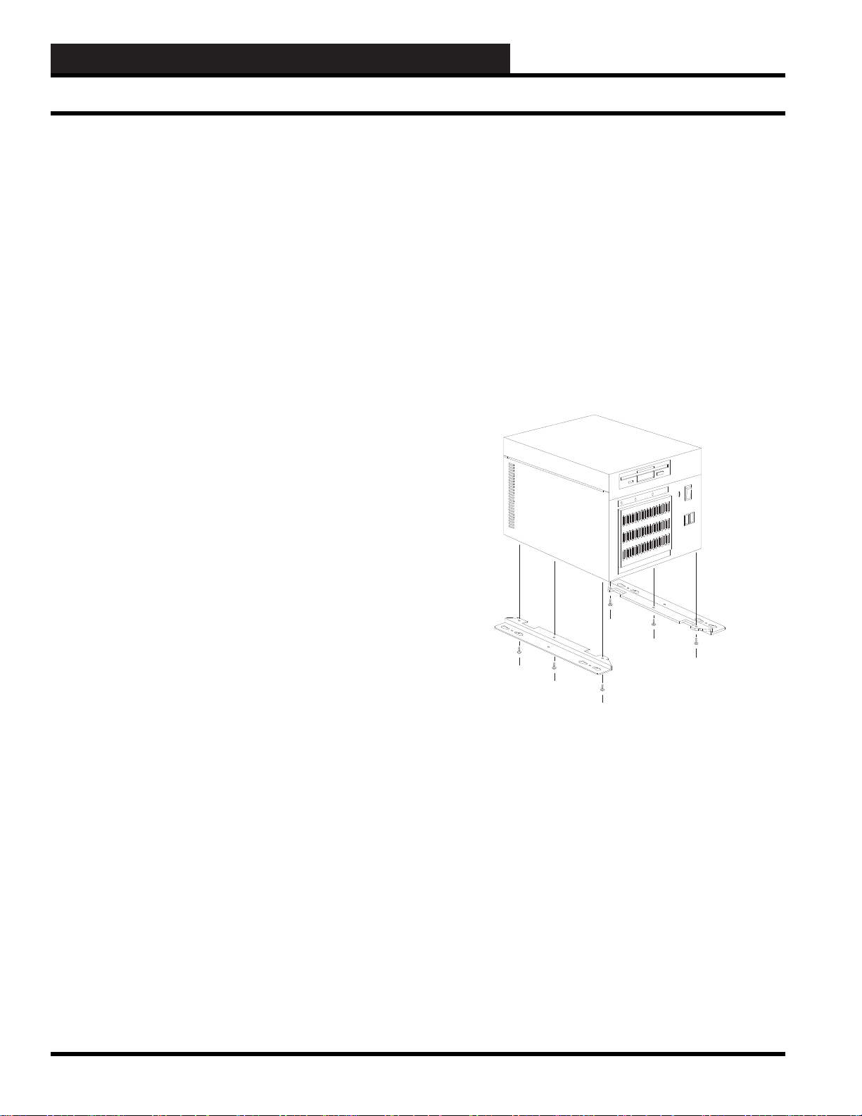
Figure 2: Installing the six screws for the two wall
mounting brackets of the WCC III – MCD Computer
Do not mount the WCC III – MCD computer straight into the
drywall. The use of a ¾-inch plywood “Backer Plate Board” is
required. You may want to paint this plywood “Backer Plate
Board” to match the color of the wall before mounting to the wall.
See Figure 3 for further application.
Backer Plate Mounting Notes:
Use correct type of wall mounting anchors for mounting on a
concrete wall for the mounting of the “Backer Plate Board” if and
when mounting the Backer Plate Board to a concrete wall. Use
at least 2-inch dry wall type screws if mounting the Backer Plate
Board to a “Dry-Wall” type wall. Mount the “Backer Plate Board”
so that the screws that are holding the “Backer Plate Board” are on
the 16-inch centers of the wall studs where applicable.
13A-4
WCC III Technical Guide
Page 7
13. WCC III - MCD INSTALLATION GUIDE
Mount the WCC III - MCD 4-½ to 5-½ feet off of the ground on a
suitable wall, in an air conditioned space. This area should not have
any radio transmitting or telephone switching gear in the space, or
near the space, or located on the back side of the adjacent wall.
Do not block the airfl ow vents that are coming out of the WCC III-
MCD. Do not apply paint to the WCC III-MCD enclosure. Do not
cover the WCC III-MCD with any protective plastic while painting
with the WCC III-MCD turned on. The UPS battery backup unit
should be located within 3 or 4 feet of this WCC III – MCD.
Wall Mounting of the WCC III - MCD
Front view with wall mounting brackets
Wall Mounting of the WCC III - MCD
Use 3/4 inch plywood for the backer plate board
(supplied by others)
Figure 3: Wall mounting instructions for the WCC III – MCD
WCC III Technical Guide
13A-5
Page 8

13. WCC III - MCD INSTALLATION GUIDE
WCC III - MCD Internet Access
System Setup
You must follow the directions in the order they are given.
Set-Up Cable Modem/Router
The WCC III-MCD uses internet access to e-mail alarms and
to provide remote access for multiple remote WCC III operator
programs. It is recommended that the WCC III-MCD computer be
connected to the internet via a high-speed cable modem router.
Step 1: You will need a high-speed cable or DSL modem/router
that is NAT enabled and it must be setup by the ISP, or by IT
(Information Technology) knowledgeable personnel, and it must
also be connected to the Internet.
Step 2: The following items are needed from your ISP (Internet
Service Provider) in order to set up the Cable / DSL modem/router
for stand alone internet access. The ISP should have already
supplied a sheet of paper that has this important information on it.
WCC III-MCD IP Address: _______._______._______._______
WCC III-MCD Subnet Mask: _______._______._______.______
WCC III-MCD Default Gateway: _______.______.______._____
The default IP addresses that the WCC III – MCD is shipped with
are:
WCC III-MCD IP Address: 192.168.100.100
WCC III-MCD Subnet Mask: 255.255.255.0
WCC III-MCD Default Gateway: 192.168.100.1
WCC III-MCD Preferred DNS Server: 208.67.222.222
WCC III-MCD Alternate DNS Server: 208.67.220.220
WCC III-MCD Preferred DNS Server:
_________._________.________._______
WCC III-MCD Alternate DNS Server:
_________._________.________._______
13A-6
WCC III Technical Guide
Page 9
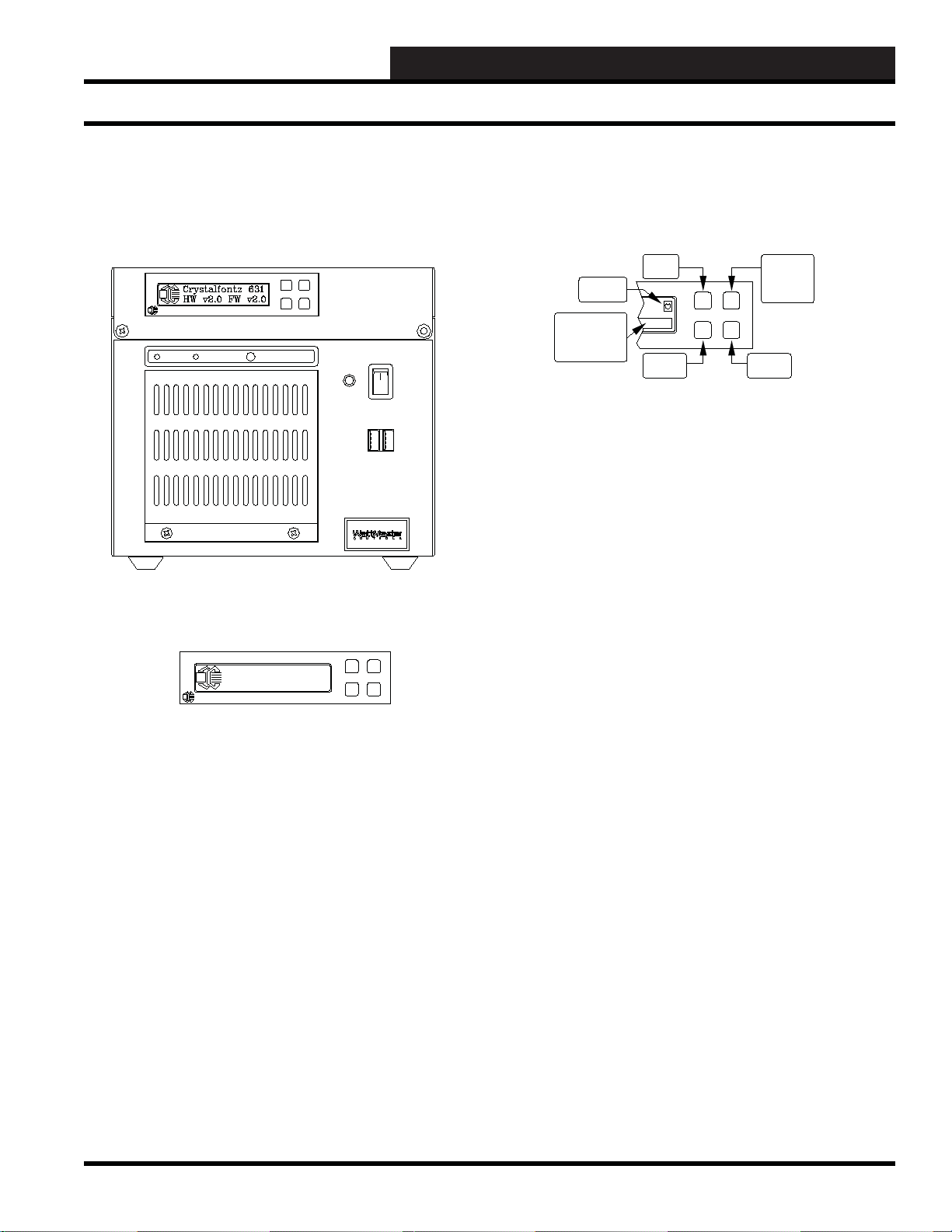
WCC III - MCD Display
13. WCC III - MCD INSTALLATION GUIDE
WCCIII - MCD Local 2 by 20 Line Display
WCC III - MCD Front View
Crystalfontz
POWER H.D.D RESET
Crystalfontz 631
HW v2.0 FW v2.0
Crystalfontz
HeartBeat
Location
Button Message
Area
| Hold
| Rotate
"UP"
Button
"DOWN"
Button
"SELECT"
"HOLD"
"ROTATE"
Button
"MENU"
Button
The LCD Display Buttons
There are four buttons on the front of the LCD display on the WCC
III - MCD.
The Upper Left button is the “UP” menu navigation button.
The Lower Left button is the “DOWN” menu navigation button.
The Upper Right button works as a “SELECT” button under the
MENU option or else it operates as a “HOLD” or “ROTATE”
button for the information screens.
The WCC III – MCD now has a 2 line by 20 character dot matrix
liquid crystal display. This LCD displays the following information:
IP ADDRESS, MCD UPTIME, RX, TX, Down, Up, User %,
System %, Nice %, Idle %.
This display is very helpful to determine if the WCC III – MCD is
functioning correctly.
WCC III Technical Guide
Also the “BUTTON MESSAGE” area will momentarily display
either “HOLD” or “ROTATE” when the Upper Right button is
depressed.
The Lower Right button is the “MENU” button. It also serves as
a “HOME” button to return to the main menu when in any of the
sub-menus.
13A-7
Page 10

13. WCC III - MCD INSTALLATION GUIDE
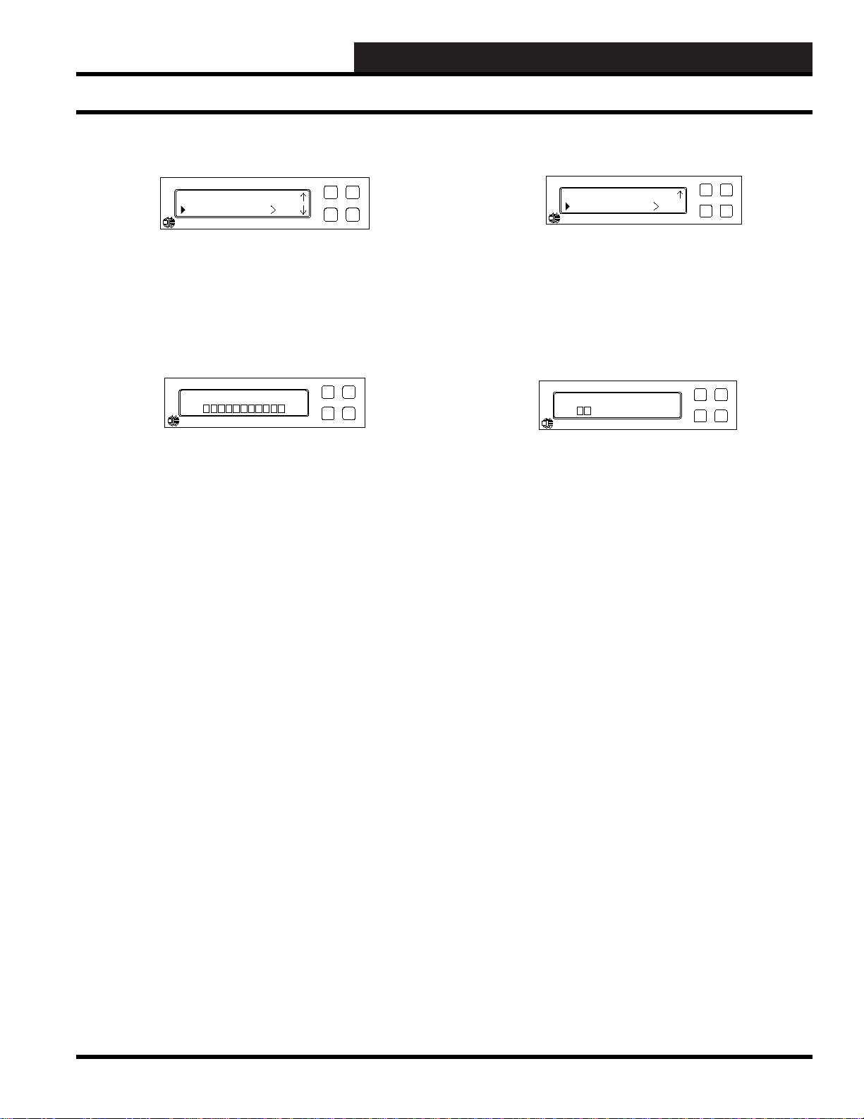
WCCIII - MCD Local 2 by 20 Line Display
SELECT
CHECK
DESELECT
HEART BEAT
UP/DOWN ITEM SELECT
SUBMENU UP SELECT
SUBMENU DOWN SELECT
The LCD Character Boxes
The Select box, Check box, and Deselect-box icons are displayed
on the LCD as a visual aid to selecting or deselecting an item.
The difference between the Select box and the Check box is that
the Select box icon is the default setting and the Check box icon is
a change to the setpoint that the user has initiated.
The Deselect box turns the selected item “OFF”.
The Heart Beat icon is to be used as a watchdog to make sure that
this Linux-based LCD program is still running and is not “Locked
Up”.
The Up/Down Item Select icon is used to display which of the
currently selected menu items is currently selected for viewing
and/or change.
WCC III MCD IPADDRESS
XXX.XXX.XXX.XXX
Crystalfontz
WCC III - MCD IP Address
This screen shows the actual IP address of the WCC III – MCD.
An Internet Protocol (IP) address is a numerical identifi cation
and logical address that is assigned to the WCC III – MCD that is
participating in a computer network that is then utilizing the Internet
Protocol for communication between its nodes. The WCC III MCD is confi gured to use the same IP address each time it powers
up - this is known as a Static IP address. In contrast, in situations
when the other computer’s IP address is assigned automatically,
it is known as a Dynamic IP address. The Static IP addresses are
manually assigned to the WCC III - MCD by an administrator.
MCD UPTIME
D.Days H.Hours m.Min
Crystalfontz
The submenu Up/Down icons are a reminder to use the Upper Left
or Lower Left buttons (UP/DOWN) to affect the changes to the
user-desired “Adjustable” settings and are used for “CONTRAST”,
“ON BRIGHTNESS”, and “OFF BRIGHTNESS” adjustments.
MCD UPTIME
D - Days, H - Hours, m - Min
This is the displayed run time total since the last reset or startup
of the WCC III – MCD. It is often used as a measure of computer
operating system reliability and stability, in that this time represents
the time that a computer can be left unattended without crashing
or needing to be rebooted for any administrative or maintenance
purposes.
13A-8
WCC III Technical Guide
Page 11

13. WCC III - MCD INSTALLATION GUIDE
Rx: 0.0 Down l
Tx: 0.0 UP 0
Crystalfontz
IP Packet
An IP packet is the formatted unit of data that is carried by a
packet mode computer network. When the data is formatted into
IP packets, the bit rate of the communication medium (Ethernet)
can better be shared among users than if the network were circuit
switched.
Rx: Displays the number of IP Packets that are currently being
received on the network card right now.
Tx: Displays the number of IP Packets that are currently being
transmitted on the network card right now.
Down: Total IP Packets that have been received on the network
card since the last bootup.
Up: Total IP Packets that have been transmitted on the network
card since the last bootup.
WCCIII - MCD Local 2 by 20 Line Display
Nice becomes useful when there are several processes that are
demanding more resources than the WCC III – MCD CPU can
provide. In this state, a higher priority process will get a larger
chunk of the WCC III – MCD CPU time than a lower priority
process. If the WCC III – MCD CPU can deliver more resources
than the processes are requesting, then even the lowest priority
process can get up to 99% of the WCC III - MCD CPU. Only the
superuser (root) may set the niceness to a smaller (higher priority)
value. On Linux it is possible to change ”/etc/security/limits.conf “
to allow other users or groups to set a low nice value.
Idle: Percentage of the WCC III – MCD CPU’s time that the CPU
were idle and the system did not do an outstanding disk I/O request.
A computer processor is described as idle when it is not being used
by any program.
Programs which make little use of the CPU Idle Time mean that
they run at a low priority so as not to impact programs that run at
normal priority like BackTask.exe. Many programs that use the
WCC III – MCD CPU idle time can cause the WCC III - MCD CPU
to always be 100% utilized, so that the time spent where the WCC
III – MCD CPU would have been idle is instead spent performing
useful computations. This generally causes the WCC III – MCD
CPU to consume more power as most modern computer’s CPUs
can enter power-save modes when they are idle.
Usr: 0.0% Nice 0.0%
Sys: 0.0% Idle100.0%
Crystalfontz
CPU Usage Percentages
Usr: Percentage of the WCC III – MCD CPU’s utilization that
occurred while executing at the user level (application). BackTask.
exe is an application.
Sys: Percentage of the WCC III – MCD CPU’s utilization that
occurred while executing at the system level (kernel). The Linux
operating system is system level.
Nice: Percentage of the WCC III – MCD CPU’s utilization that
occurred while executing at the user level.
Nice (pronounced /na is/) is a program that’s found within Linux.
Nice directly maps to a kernel call of the same name. For any
given process, it changes the priority in the kernel’s scheduler. A
niceness of −20 is the highest priority and 19 is the lowest priority.
The default niceness for any process is inherited from its parent
process, usually 0.
LCDproc Menu
Options
Crystalfontz
Options Menu
Press the Lower Right button (MENU) to select the “LCDproc
Menu” selection.
Press the Upper Right button (SELECT) to select the “Option”
selection.
WCC III Technical Guide
13A-9
Page 12

13. WCC III - MCD INSTALLATION GUIDE
WCCIII - MCD Local 2 by 20 Line Display
OPTIONS
Heartbeat
Crystalfontz
Options Menu – Heart Beat Selection
Press either the Upper Left or Lower Left buttons (UP/DOWN)
to select the following user settable options: “Heart Beat”,
“Backlight”, or “CFontzPacket”.
Press the Upper Right button (SELECT) to select or toggle the
“Heartbeat” selection setting ON or OFF with either the X box,
Check box or No box icon.
Or press the Lower Left button (DOWN) to select the “Backlight”
selection.
Or press the Lower Left button (DOWN) twice to select the
“CFontzPacket” selection.
Heartbeat
Backlight
Crystalfontz
Options Menu – Backlight Selection
Press the Upper Right button (SELECT) to select or toggle the
“Backlight” selection setting ON or OFF with either the X box,
Check box or No box icon.
Heartbeat
CFontxPacket
Crystalfontz
Options Menu – CfontzPack et Submenu
Press either the Upper Left or Lower Left buttons (UP/DOWN)
to select the following user settable options: “Contrast”, “On
Brightness”, or “Off Brightness”.
Or press the Upper Left button (UP) to select the “HEART BEAT”
selection.
Or press the Upper Left button (UP) twice to select the
“BACKLIGHT” selection.
CFontzPacket
Contrast
Crystalfontz
Options Menu – CfontzPack et Submenu – Contrast
Selection
Press the Upper Right button (SELECT) to select the “Contrast”
selection setting.
Or press the Upper Left button (UP) to select the “Heartbeat”
selection.
Or press the Lower Left button (DOWN) to select the
“CFontzPacket” selection.
13A-10
Contrast
min max
Crystalfontz
Options Menu – CfontzPack et Submenu – Contrast
Selection – Contrast Setting
Press either the Upper Left or Lower Left buttons (UP/DOWN) to
affect the change to the user desired “Contrast” setting.
WCC III Technical Guide
Page 13
13. WCC III - MCD INSTALLATION GUIDE
WCCIII - MCD Local 2 by 20 Line Display
Contrast
On Brightness
Crystalfontz
Options Menu – CfontzPack et Submenu – On
Brightness Selection
Press the Upper Right button (SELECT) to select the “On
Brightness” selection setting.
On Brightness
min max
Crystalfontz
Options Menu – CfontzPack et Submenu – On
Brightness Selection – On Brightness Setting
Press either the Upper Left or Lower Left buttons (UP/DOWN) to
affect the change to the user desired “On Brightness” setting.
On Brightness
Off Brightness
Crystalfontz
Options Menu – CfontzPack et Submenu – Off
Brightness Selection
Press the Upper Right button (SELECT) to select the “Off
Brightness” selection setting.
Off Brightness
min max
Crystalfontz
Options Menu – CfontzPack et Submenu – Off
Brightness Selection – Off Brightness Setting
Press either the Upper Left or Lower Left buttons (UP/DOWN) to
affect the change to the user desired “Off Brightness” setting.
WCC III Technical Guide
13A-11
Page 14

13. WCC III - MCD INSTALLATION GUIDE
<<<LOCAL LOOP>>> AZWR-LL-WG-18>>> E76191 CL2P 18AWG (UL) 012112 FT
<<<NETWORK LOOP>>> AZWR-NL-WR-18>>> E76191 CL2P 18AWG (UL) 012112 FT
WATTMASTER LOCAL LOOP WIRE
WATTMASTER NETWORK LOOP WIRE
RS-485 Communication Wiring
The WCC III System RS-485
Communication Wiring
The WCC III - MCD can communicate with up to 239 satellite
controllers via a two-wire RS-485 communication loop. On the
back of the WCC III – MCD there are two RS-485 communication
loop ports that come as standard. Each one of these communications
loop ports can communicate with up to 60 satellites for a total of
120 satellites.
Two more additional RS-485 communication loop ports can be
added at an additional cost for any WCC III system that has more
than 120 satellites. The two-wire RS-485 communication loop
should be stranded 2 wire twisted pair of 18-gauge wire with a
shield wire, and it also must be plenum rated were applicable.
The use of stranded wire is mandatory to ensure a good connection
with the ¼ inch Sta-Con connectors which are used to terminate
the wires at the satellite controllers. The RS-485 communication
wire does not have to be run from each satellite controller back to
the WCC III – MCD, but rather the RS-485 communication wire
can be “daisy-chained,” which means that only one twisted pair of
wires is connected to each of the WCC III - MCD communications
loops. The maximum allowable length of wire from the WCC
III - MCD to the farthest satellite is 4000 feet per RS-485
communications loop.
NOTE: A length greater than 4000 feet is allowed under
certain circumstances. Consult the factory for assistance if the
communications loop required for your application will exceed
4000 feet.
The RS-485 wire specifi cations are generally a stranded 18-
gauge - 2 wire twisted pair with shield. 18-gauge stranded wire is
mandatory to ensure a good connection with the ¼ inch Sta-Con
connectors, which are used to terminate the wires at the WCC III
- MCD and at the satellite controllers. The old SAT II Manchester
communications loop was supposed to have used a 2-wire twisted
pair with shield, but this was not used in every installation. This
old SAT II communications loop should not be used for the new
SAT III communications loop. A new RS-485 communications
loop should be ran to each new replacement SAT III controller.
The shield wire must be used on the new SAT III controller, as
it provides a “ground” reference for the RS-485 communication
loop. WattMaster Controls sells two versions of 18-gauge - 2-wire
twisted pair with shield communications wire— (1) WattMaster
part #WR-NL-WR-18 which is marked “Network Loop” with a
red stripe for rapid identifi cation. This connection is intended to
run from the WCC III – MCD to the SAT III, SAT 3C/D/F, SAT
3P, and then to the next SAT 3 type controllers. (2) WattMaster part
# WR-LL-WG-18 which is marked “Local Loop” with a green
stripe for rapid identifi cation for the TUC loops that run from the
SAT 3C/D/F controllers out to the TUC controllers.
“Wire Nuts” on the RS-485 communications loop should be avoided
at all costs. As an alternative to the “Wire Nuts”, WattMaster
Controls has a Power and Switchable RS-485 communications
board, and the WattMaster part number is PL102224. This Power
and Switchable RS-485 communications board can be thought of
as a 24-VAC power and communication distribution system for
the SAT III communications loop, and this board will aid in initial
startup and future troubleshooting of the SAT III communications
loop. These boards should be used on a fl oor-by-fl oor basis. This
Power and Switchable RS-485 communications board is also
available in a small metal electrical enclosure.
The wire that makes up the communication loop should be
shielded. Shielded cable has an aluminum jacket over the wires
that could act as an “antenna” to carry away any “stray” electrical
signals that could interfere with the communication process. The
shield should be grounded throughout the SAT Loop.
Figure 4 WattMaster Controls various communications loop wire
13A-12
WCC III Technical Guide
Page 15

13. WCC III - MCD INSTALLATION GUIDE
WCC III - MCD Typical System Architecture
Figure 5: The WCC III typical system architecture with POWER and SWITCHABLE COMM boards
Figure 6: WCC III typical system architecture without the POWER and SWITCHABLE COMM boards
WCC III Technical Guide
13A-13
Page 16

13. WCC III - MCD INSTALLATION GUIDE
Initiating the System
The SAT RS-485 communication loop wires are connected to the
“R” and “T” and shield terminals on the satellite controllers using
¼-inch Sta-Con connectors. Make sure the polarity is correct.
That is to say, the wire connected to the “R” and “T” terminal on
the MCD must be connected to the “R” and “T” terminal on the
satellite controllers. If the “R” and “T” and shield wires are crossed,
the WCC III system will not communicate. The shield should be
connected together when the cable is cut in order to terminate the
wires at the satellite controller.
The communication loop wire from the WCC III - MCD is
connected to one of the “R” and one of the “T” terminals on the
satellite controller, which is physically located nearest the WCC
III - MCD. The other “R” and “T” terminals located on the satellite
controller can be used to extend the two-wire loop to the next
satellite controller, or the wires can branch off of a two-wire loop
running through the center of a building as shown in Figure 6.
NOTE: The shield wire must be connected at each and every
Satellite Controller also.
INITIA TING THE SYSTEM
After the satellite controllers have been installed and powered
up, the WCC III - MCD set up, and the 2-wire communications
line connected between all of the satellite controllers and also
connected to the WCC III - MCD, then the WCC III data fi les need
to be loaded into the WCC III - MCD. This is best accomplished by
using the WCC “mcd-menu” batch fi le, remotely with the Webmin
program, or by directly using the Linux command prompt on the
WCC III - MCD.
NOTE: When converting the WCC II data fi les to WCC III
type data fi les. The WCC II data fi les have to be converted
to the new WCC III type data fi les using the WCCUtilities.
exe program. Then these new WCC III data fi les need to be
installed on the WCC III - MCD. This is best accomplished
by using the WCC “mcd-menu” batch fi le, remotely with the
Webmin program, or by directly using the Linux command
prompt on the WCC III - MCD.
The WCC III – MCD has two solid state hard drives, one that has
the Linux operating system along with the backtask program, and
one that has the daily/monthly WCC III backup data fi les on it.
A USB thumb drive can be used to shuffl e the data in and out of the
WCC III – MCD. Another program called “Webmin” is primarily
used to administer the more advanced setup features on the WCC
III –MCD. This “Webmin” program requires an internet browser,
such as Mozilla, or Microsoft Internet Explorer to function. This
“Webmin” program can be used over the internet/intranet or
locally with a network crossover cable. The “Webmin” program is
pre-installed on the Linux OS hard drive on the WCC III – MCD.
There are three password levels for the “Webmin” program, one
for the simple user, one for the contractor level, and one for the
WattMaster factory administrator.
MCD System Files
The Backtask program on the MCD is stored on the solid state
hard disk, so after boot-up, the system start up fi les will cause the
Backtask Program to run.
CAUTION: The MCD will not communicate with the satellite
controllers while it is going through the “re-boot” process. If
the satellite controllers do not communicate with the MCD for
approximately three minutes, they will go into local set. The
time it takes for the system to “re-boot” should not cause the
satellite controllers to go into local set.
The hard disk can hold a vast amount of data which can accidentally
be erased or lost due to system malfunction, operator error, etc.
Therefore it is extremely important to make a back-up copy of
the data on the hard disk. As you program a system to control a
building, information is written on the disks. Therefore, back-up
copies of programming data fi les on the hard disk should be made
after the system has been programmed to control the building. This
can be done remotely through the WCC Utility program.
13A-14
WCC III Technical Guide
Page 17

13. WCC III - MCD INSTALLATION GUIDE
The WCC III - MCD
The WCC III - MCD
Overview
The WCC III – MCD was converted from the Windows XP
operating system over to the Ubuntu version of Linux using the
command line interface only and was then released by WattMaster
Controls in October of 2009. The main function of the WCC
III – MCD is to provide a hardware and software platform for a
program that WattMaster Controls has developed that is called
“BACKTASK.exe”. The BACKTASK.exe program is a multiple
BACKground TASKing application program.
BACKTASK.EXE (SS5009)
The BACKTASK.exe program performs many functions such
as:
• USB communications to the internal MCOMM board
• Time clock functions
• Analog/binary global processing
• Overrides of control points
• Holiday scheduling
• Optimal starts
• PID programs
• Shed /Restore programs
• Duty cycle programs
• Proportional Programs
• Tenant Overrides
• Emailing of alarms
The BACKTASK.exe program also provides for remote IP
connection to a set of windows-based programs generally referred
to as the WCC III programs. This WCC III – MCD also has
hardware (WCCIII MCOMM board) that interfaces to a RS-485
communications loop that connects to SAT III type controllers for
building automation controls.
be plugged into a (NON – UPS) 120VAC outlet. The power cord
for the WCC III – MCD is to be connected to a dedicated UPS
(Uninterruptible Power Supply) outlet so that the MCD will keep
running during a minor power outage. The Cable/DSL modem/
router should also be plugged into one of these dedicated UPS
(Uninterruptible Power Supply) outlets.
MCD-Menu Program Overview
WattMaster Controls has developed a simple setup installation
program for the Linux command line interface, and this program
is called mcd-menu. Prior knowledge of Linux is not required, but
would be helpful. This mcd-menu program has eleven subprograms
incorporated into it that will allow for the following operations to
be preformed:
• The setup of the Network IP Confi guration of the
WCC III – MCD network card interface
• Copying of the BackTask specifi c data fi les to the root
of the USB Drive
• Restoring of the BackTask specifi c data fi les from the
root of the USB Drive
• The resetting of the WCC III - MCD IP address back
to the WattMaster factory Default IP Address settings
• The resetting of the WCC III - MCD DNS settings
back to the WattMaster factory default DNS settings
• The restarting of the 2 by 20 line LCD Driver that is
located on the front of the WCC III - MCD
• The restarting of the 2 by 20 line LCD Display that is
located on the front of the WCC III - MCD
• The testing of the Internet Connection, from the WCC
III - MCD to the internet
• The testing of DNS Settings, from the WCCIII - MCD
to the internet
• The shutdown of the WCC III - MCD – properly
closing down
• The shutdown and restart of the WCC III - MCD
Watchdog Circuit/P ow er F ail
If the BACKTASK.exe program is not running on the WCCIII
- MCD, there is a watchdog circuit that will restart the WCCIII
– MCD. This watchdog circuit may interfere with the installation
of new BACKTASK.exe software. There is a way to disable this
watchdog circuit. Please contact WattMaster Controls for further
information on temporarily disabling this watchdog circuit. In
addition to this watchdog circuit, there is a small wall wart 24vac
transformer that must be connected to 120VAC or else the WCCIII
- MCD will restart every two minutes. This is part of the power fail
design circuit of the WCC III – MCD. This transformer is meant to
WCC III Technical Guide
The Webmin access method can also accomplish all of these same
tasks, but is a little bit harder to use and is meant to be more of an
“off site” management tool for the WCC III - MCD. The mcdmenu program is meant to be used as the initial IP setting tool and
BACKTASK data fi le loading tool for the WCC III - MCD. For
this a monitor and keyboard needs to be connected temporarily just
for the initial IP setup and BACKTASK data fi le loading.
13A-15
Page 18

13. WCC III - MCD INSTALLATION GUIDE
Using the MCD-Menu Program
Using the MCD-Menu Program
Overview
The default administration username is wcciii and the password is
wt@@58 This user name and password are both CAP sensitive,
and should be entered in lower case letters only.
1. Type “mcd-menu” at the wcciii@wcciii-mcd:~$ prompt (view
only – restricted access). You can perform very few functions
as “View only restricted access”, such as Copy/restore WCCIII
data fi les.
2. To do the root level tasks like confi gure IP address,
shutdown the WCC III - MCD, reboot the WCC III - MCD,
reset the WCC III – MCD IP addresses and DNS settings
to DEFAULT confi gurations, and of course, copy/restore
WCCIII data fi les, you must be signed in as a “root” user.
You must be very careful signed in as a root user, because
you can render your WCC III - MCD system unable to
communicate with the outside world if improperly used.
If you have selected a command and you are not signed in as a
root user, it will give you a warning message as listed below:
**************************************************
* *
* Warning: The program is not running as root. *
* Interface confi gurations or saving may fail! *
* *
**************************************************
NOTE: DO NOT run the mcd-menu program from inside
WebMin’s Command Shell. It will not work there. This mcdmenu program is meant to work only from the telnet/ssh
session or from the actual console (i.e. keyboard and monitor
that is connected to the WCC III - MCD).
Running the mcd-menu program
Step 1:
and the password is wt@@58. Type mcd-menu at the prompt
(view only – restricted access).
Step 2: The following fi rst main menu screen should appear:
Please Pick a Function:
1. Setup Network Confi guration
2. Copy BackTask Files to USB Drive
3. Restore BackTask Files from USB Drive
4. Reset MCD to Default IP Address
5. Reset MCD to Default DNS Settings
6. Restart LCD Driver
7. Restart LCD Display
8. Test Internet Connection
9. Test DNS Settings
10. Shutdown MCD
11 Total Choices
Using the default low level, the username is wcciii
The mcd-menu is straight forward. You can select the desired
function by number (1 to 11) and hit the enter key to execute
the desire function. You can quit this mcd-menu program at any
time by hitting the “q” and then the enter key to quit. Then type
“exit” at the wcciii-mcd:~$prompt.
Helpful hint: While at the wcciii@wcciii-mcd:~$ prompt you
can select/toggle through previously entered commands with
the “UP” arrow key.
The new fi les are rolled into the installation fi les so they will
be available on new systems. They can also be pushed or
updated to older systems via secure ftp and then run from the
shell. Alternatively, they can also be upload to the WCC III
– MCD from inside the WebMin program and then run from
the command line from within the browser. This mcd-menu
program may be run remotely from PuTTY which is a terminal
emulator application program, provided that this program is
installed and properly setup on your computer.
13A-16
Press ENTER (or “d”) to scroll downward
OR “u” to scroll upward (Press “q” to quit)
PLEASE ENTER A CHOICE: ___
WCC III Technical Guide
Page 19

13. WCC III - MCD INSTALLATION GUIDE
Using the MCD-Menu Program
Step 3: Pressing the “enter” key or the “d” key will result
in the next (second) menu screen appearing. The following
second main menu screen should appear:
Please Pick a Function:
11. Shutdown and Reboot MCD
11 Total Choices
Press ENTER (or “d”) to scroll downward
OR “u” to scroll upward (Press “q” to quit)
PLEASE ENTER A CHOICE: ___
Helpful hint: You do not have to use the “u” or “d” keys and then
the “enter” to toggle between the fi rst and second menus. By using
the just “enter” key you can toggle between the fi rst menu screen
with selections of 1 to 10 and the second menu screen that has
selection 11 only.
Setup Network Confi guration (Choice #1)
This sub program will allow you to set the IP confi guration of the
WCC III – MCD. You will be prompted to enter a IP Address in
the XXX.XXX.XXX.XXX format. If you do not have all of the
following information, then you should not proceed any further.
The values should be written below for future reference.
Static IP address ___ ___ ___ . ___ ___ ___ . ___ ___
___ . ___ ___ ___ Must be static.
You will be now be prompted to enter the following data, and if you
do not want to change the address listed within the listed brackets
[ ] then just press the enter key and the value in the brackets [ ]
will not change.
Enter interface confi guration data:
Interface to confi gure: [eth0] __
IP address: [192.168.100.100] __
Netmask: [255.255.255.0] __
Gateway (none for no gateway): [192.168.100.1] __
Nameservers (blank separate list):
[208.67.222.222_208.67.220.220] __
Interface to confi gure: [eth0] __ There are two possible
entries here “eth0” and “eth0:0”
eth0 is the default main IP address for the WCC III – MCD.
eth0:0 is the secondary IP address for the WCC III – MCD and
it is meant for direct connection from the WCC III – MCD to a
local computer (Laptop) via a Ethernet crossover cable.
IP address: [192.168.100.100] __ This IP address must be
supplied by your internet provider or by your network IT
personnel. It must be a “static” as in not changing.
Netmask: [255.255.255.0] __ This IP address must be
supplied by your internet provider or by your network IT
personnel.
Gateway (none for no gateway): [192.168.100.1] __ This IP
address must be supplied by your internet provider or by your
network IT personnel.
Subnet mask ___ ___ ___ . ___ ___ ___ . ___ ___
___ . ___ ___ ___
Gateway ___ ___ ___ . ___ ___ ___ . ___ ___ ___ .
___ ___ ___
Nameserver ___ ___ ___ . ___ ___ ___ . ___ ___ ___
. ___ ___ ___
Nameserver ___ ___ ___ . ___ ___ ___ . ___ ___ ___
. ___ ___ ___ Optional
Nameserver ___ ___ ___ . ___ ___ ___ . ___ ___ ___
. ___ ___ ___ Optional
WCC III Technical Guide
Nameservers (blank separate list):
[208.67.222.222_208.67.220.220] __
address for a DNS server.
Some internet service providers do not have a static IP
address. They use what is called static host names, which
correspond to a actual static IP address. You can enter more
than one IP address here, a primary and a secondary,
and please note that they must be separated by a space.
For example, on the Internet there exists a special case of
nameservers lookup sites, the so called Domain Name System
(DNS) servers, which are used to translate a static hostname or
a domain name (for example, ‘WCC-CONTROLS.com’) to its
corresponding binary identifi er (the IP address 76.12.37.232),
or vice versa.
This is the actual IP
13A-17
Page 20

13. WCC III - MCD INSTALLATION GUIDE
Using the MCD-Menu Program
After you have entered in all of the required IP addresses, subnet
masks, Gateways, and/or Nameservers, the program will now
change the internal IP network confi guration fi les within the Linux
operating system of the WCC III – MCD. It will take a few seconds
to do this function, and will display the following messages:
Confi guring interface:
/sbin/ifconfi g eth0 192.168.100.100 netmask 255.255.255.0
broadcast 192.168.100.255
Deleting old interface route:
/sbin/route del -net 192.168.100.0 netmask 255.255.255.0 eth0
Setting interface route:
/sbin/route add -net 192.168.100.0 netmask 255.255.255.0
eth0
Deleting old default route:
/sbin/route del default
Setting default route:
/sbin/route add default gw 192.168.100.1
Writing /etc/network/interfaces:
Copy BackT ask da ta Files to USB Drive (Choice #2)
This sub program will copy all of the useful WCC III data fi les to
a USB drive (User / Contractor provided), assuming that there is a
USB drive plugged into the USB port on the WCC III – MCD. It
will copy all of these fi les to the root of the USB drive.
If there is not a USB hard drive in the USB port on the front of the
WCCIII – MCD, this program assumes that there is a USB drive
there even if it is not there. It will not report that there is a drive
reading or writing error or any other errors. So when backing up,
make sure that there is a USB hard drive in the USB socket port on
the front of the WCCIII – MCD, and also there should be a LED
on this USB hard drive that should light up when data is written or
read from it. Please verify that this LED operates when backing up
data to this USB hard drive.
All WCC III jobsites have multiple specifi c custom data fi les that
are the responsibility of the end user and/or mechanical contractor.
Any loss or the retention of these jobsite specifi c custom data fi les
are not within WattMaster Controls Inc. liabilities.
The following will be displayed on the screen:
Selecting Copy BackTask Files to USB Drive.
Writing /etc/resolv.conf:
When completed the following information will be displayed:
New netstat settings:
192.168.100.100 0.0.0.0 255.255.255.0 U 0 0 0 eth0
192.168.200.0 0.0.0.0 255.255.255.0 U 0 0 0 eth0
0.0.0.0 192.168.100.1 0.0.0.0 UG 0 0 0 eth0
Network Confi guration Done.
**************************************************
* Exiting Program. *
**************************************************
wcciii@wcciii-mcd:~$
The mcd-menu program, as part of the setup process for the
IP connections, has on purpose exited the mcd-menu program.
This is normal operation.
Copying fi le: /home/wcciii/.wine/drive_c/Backtask/
AlarmBits.dat
Copying fi le: /home/wcciii/.wine/drive_c/Backtask/
AlarmMessage.dat
Copying fi le: /home/wcciii/.wine/drive_c/Backtask/
DutyCycleSchedule.dat
Copying fi le: /home/wcciii/.wine/drive_c/Backtask/
EnergyConsumption.dat
Copying fi le: /home/wcciii/.wine/drive_c/Backtask/
GeneralMessage.dat
Copying fi le: /home/wcciii/.wine/drive_c/Backtask/
GlobalAnalog.dat
Copying fi le: /home/wcciii/.wine/drive_c/Backtask/
GlobalBinary.dat
Copying fi le: /home/wcciii/.wine/drive_c/Backtask/
HolidaySchedule.dat
Copying fi le: /home/wcciii/.wine/drive_c/Backtask/
LookUpTable.dat
Copying fi le: /home/wcciii/.wine/drive_c/Backtask/
NetworkInformation.dat
Copying fi le: /home/wcciii/.wine/drive_c/Backtask/
OperatorCode.dat
Copying fi le: /home/wcciii/.wine/drive_c/Backtask/
OptimalSchedule.dat
Copying fi le: /home/wcciii/.wine/drive_c/Backtask/
OverrideSchedule.dat
Copying fi le: /home/wcciii/.wine/drive_c/Backtask/
PidProgram.dat
13A-18
WCC III Technical Guide
Page 21

13. WCC III - MCD INSTALLATION GUIDE
Using the MCD-Menu Program
Copying fi le: /home/wcciii/.wine/drive_c/Backtask/
ProportionalReset.dat
Copying fi le: /home/wcciii/.wine/drive_c/Backtask/
ShedRestoreSchedule.dat
Copying fi le: /home/wcciii/.wine/drive_c/Backtask/
StatusMessage.dat
Copying fi le: /home/wcciii/.wine/drive_c/Backtask/
SystemParameter.dat
Copying fi le: /home/wcciii/.wine/drive_c/Backtask/table.dat
Copying fi le: /home/wcciii/.wine/drive_c/Backtask/
TenantEvent_001_2009_09.dat
Copying fi le: /home/wcciii/.wine/drive_c/Backtask/
TenantEvent_004_2009_10.dat
Copying fi le: /home/wcciii/.wine/drive_c/Backtask/
TenantOverride.dat
Copying fi le: /home/wcciii/.wine/drive_c/Backtask/
TenantOverrideRecord.dat
Copying fi le: /home/wcciii/.wine/drive_c/Backtask/
UnitMessage.dat
Copying fi le: /home/wcciii/.wine/drive_c/Backtask/
WeekSchedule.dat
Done copying .dat fi les.
Returning to Main Menu.
The screen should now take you back to the mcd-menu main
screen after about a second or two.
Restore BackT ask data Files to USB Driv e (Choice
#3)
This sub program will copy all of the useful WCC III data fi les
from a USB drive (User/Contractor provided), assuming that
there is a USB drive plugged into the USB port on the WCC
III – MCD. It will copy all of these fi les to the //home/wcciii/.
wine/drive_c/Backtask/ subdirectory of the WCC III – MCD
solid state hard drive.
If there is not a USB hard drive in the USB port on the front of
the WCCIII – MCD, this program assumes that there is a USB
drive there even if it is not there. It will not report that there is
a drive reading or writing error or any other errors. So when
backing up, make sure that there is a USB hard drive in the USB
socket port on the front of the WCCIII – MCD, and also there
should be a LED on this USB hard drive that should light up
when data is written or read from it. Please verify that this LED
operates when restoring data from this USB hard drive.
All WCC III jobsites have multiple specifi c custom data fi les
that are the responsibility of the end user and or mechanical
contractor. Any loss or the retention of these jobsite specifi c
custom data fi les are not with in WattMaster Controls Inc.
liabilities.
The following will be displayed on the screen:
Selecting Restore BackTask Files from USB Drive.
Copying fi le: /home/wcciii/.wine/dosdevices/d:/AlarmBits.dat
Copying fi le: /home/wcciii/.wine/dosdevices/d:/
AlarmMessage.dat
Copying fi le: /home/wcciii/.wine/dosdevices/d:/
DutyCycleSchedule.dat
Copying fi le: /home/wcciii/.wine/dosdevices/d:/
EnergyConsumption.dat
Copying fi le: /home/wcciii/.wine/dosdevices/d:/
GeneralMessage.dat
Copying fi le: /home/wcciii/.wine/dosdevices/d:/GlobalAnalog.
dat
Copying fi le: /home/wcciii/.wine/dosdevices/d:/GlobalBinary.
dat
Copying fi le: /home/wcciii/.wine/dosdevices/d:/
HolidaySchedule.dat
Copying fi le: /home/wcciii/.wine/dosdevices/d:/LookUpTable.
dat
Copying fi le: /home/wcciii/.wine/dosdevices/d:/
NetworkInformation.dat
Copying fi le: /home/wcciii/.wine/dosdevices/d:/OperatorCode.
dat
Copying fi le: /home/wcciii/.wine/dosdevices/d:/
OptimalSchedule.dat
Copying fi le: /home/wcciii/.wine/dosdevices/d:/
OverrideSchedule.dat
Copying fi le: /home/wcciii/.wine/dosdevices/d:/PidProgram.
dat
Copying fi le: /home/wcciii/.wine/dosdevices/d:/
ProportionalReset.dat
Copying fi le: /home/wcciii/.wine/dosdevices/d:/
ShedRestoreSchedule.dat
Copying fi le: /home/wcciii/.wine/dosdevices/d:/
StatusMessage.dat
Copying fi le: /home/wcciii/.wine/dosdevices/d:/
SystemParameter.dat
Copying fi le: /home/wcciii/.wine/dosdevices/d:/table.dat
Copying fi le: /home/wcciii/.wine/dosdevices/d:/
TenantEvent_001_2009_09.dat
Copying fi le: /home/wcciii/.wine/dosdevices/d:/
TenantEvent_004_2009_10.dat
Copying fi le: /home/wcciii/.wine/dosdevices/d:/
TenantOverride.dat
WCC III Technical Guide
13A-19
Page 22

13. WCC III - MCD INSTALLATION GUIDE
Using the MCD-Menu Program
Copying fi le: /home/wcciii/.wine/dosdevices/d:/
TenantOverrideRecord.dat
Copying fi le: /home/wcciii/.wine/dosdevices/d:/UnitMessage.
dat
Copying fi le: /home/wcciii/.wine/dosdevices/d:/
WeekSchedule.dat
Done copying .dat fi les.
Returning to Main Menu.
The screen should now take you back to the mcd-menu main
screen after about a second or two.
Reset MCD to Default IP Address (Choice #4)
There are times when you may want to reset the IP address
back to WattMaster Control’s factory default settings. This
is primarily done at WattMaster on new systems before they
are sent out to the end user/contractor/customer. It is a base
known starting point. Please note that this choice will reset both
of the eth0 and eth0:0 ethernet confi gurations. The following
information will be displayed on the screen:
Selecting Reset MCD to Default IP Address.
IP Address restored to Default.
IP Address Confi guration is:
# This fi le describes the network interfaces available on your
system
# and how to activate them. For more information, see
interfaces(5).
iface eth0:0 inet static
address 192.168.200.200
netmask 255.255.255.0
broadcast 192.168.200.255
network 192.168.200.0 * Reconfi guring network
interfaces... SIOCSIFFLAGS: Cannot assign requested
address
* Stopping NTP server ntpd
...done.
* Stopping NTP server ntpd
[ OK ]
...done.
* Starting NTP server ntpd
...done.
* Starting NTP server ntpd
...done.
The screen should now take you back to the mcd-menu main
screen after about a second or two.
Reset MCD to Default DNS Settings (Choice #5)
There are times when you may want to reset the DNS settings
back to WattMaster Control’s factory default settings. This is
primarily done at WattMaster on new systems before they are
sent out to the end user /contractor/customer. It is a base known
starting point. The following information will be displayed on
the screen:
Selecting Reset MCD to Default DNS Settings.
DNS Settings restored to Default.
Contents of /etc/resolv.conf are:
# The loopback network interface
auto lo eth0 eth0:0
iface lo inet loopback
# The primary network interface
iface eth0 inet static
address 192.168.100.100
netmask 255.255.255.0
network 192.168.100.0
broadcast 192.168.100.255
gateway 192.168.100.1
post-up iptables-restore < /etc/iptables.up.rules
# dns-* options are implemented by the resolvconf
package, if installed
13A-20
search parkville.wattmaster.com
nameserver 208.67.222.222
nameserver 208.67.220.220
* Reconfi guring network interfaces...
SIOCSIFFLAGS: Cannot assign requested address
* Stopping NTP server ntpd
...done.
[ OK ]
* Stopping NTP server ntpd
...done.
* Starting NTP server ntpd
...done.
* Starting NTP server ntpd
...done.
The screen should now take you back to the mcd-menu main
screen after about a second or two.
WCC III Technical Guide
Page 23

13. WCC III - MCD INSTALLATION GUIDE
Using the MCD-Menu Program
Restart LCD Driver (Choice #6)
On the front of the WCC III – MCD, there is a 2 by 20 line
LCD display. This 2 by 20 line LCD display will display the
following information:
WCCIII - MCD IP ADDRESS
WCCIII - MCD UPTIME
WCCIII - MCD IP RECEIVE AND TRANSMIT PACKETS
WCCIII - MCD CPU UTILIZATION
This will stop the LCD driver and then restart it. The reasons
why you might want to restart the 2 by 20 line LCD driver are:
There may have been a issue with a stuck or blanked out screen,
or the USB connection to the 2 by 20 line LCD display might
have been disconnected or locked up.
If you have selected to restart the LCD driver, then the following
will be displayed on the screen:
Selecting Restart LCD Driver.
Restarting LCD Driver...
Restarting LCDd: Stopping LCDd: LCDd.
Starting LCDd: LCDd.
Stopping LCD Display...
kill: 74: Usage: kill [-s sigspec | -signum | -sigspec] [pid |
job]... or
kill -l [exitstatus]
LCD Display is stopped
Starting LCD Display...
LCD Display is now started.
The screen should now take you back to the mcd-menu main
screen after about a second or two.
Test Internet Connection (Choice 8)
If you have selected to Test the Internet Connection, then the
following will be displayed on the screen:
Selecting Test Internet Connection.
**************************************************
* *
* Internet is online. *
* *
**************************************************
The screen should now take you back to the mcd-menu main
screen after about a second or two.
Restart LCD Display (Choice #7)
On the front of the WCC III – MCD, there is a 2 by 20 line LCD
display. This display will display the following information:
WCCIII - MCD IP ADDRESS
WCCIII - MCD UPTIME
WCCIII - MCD IP RECEIVE AND TRANSMIT PACKETS
WCCIII - MCD CPU UTILIZATION
This will stop the LCD display program and then restart it.
The reasons why you might want to restart the 2 by 20 line
LCD display are: There may have been a issue with a stuck or
blanked out screen, or the USB connection to the 2 by 20 line
LCD display might have been disconnected or locked up.
If you have selected to restart the LCD display, then the
following will be displayed on the screen:
Selecting Restart LCD Display.
Restarting LCD Display...
Test DNS Settings (Choice 9)
If you have selected to Test DNS Settings, then the following
will be displayed on the screen:
Selecting Test DNS Settings.
Testing DNS Setting in /etc/resolv.conf...
www.google.com is online.
www.yahoo.com is online.
www.wcc-controls.com is online.
DNS is resolving correctly.
The screen should now take you back to the mcd-menu main
screen after about a second or two.
WCC III Technical Guide
13A-21
Page 24

13. WCC III - MCD INSTALLATION GUIDE
Using the MCD-Menu Program
Shutdown MCD (Choice 10)
There are times that occur when you would need to shutdown
the WCC III – MCD. This is generally done when servicing the
WCC III – MCD or when you perform software updates on the
WCC III – MCD.
If you have selected to shutdown the MCD, then the following
will be displayed on the screen:
Selecting Shutdown MCD.
**************************************************
* *
* Shutdown MCD *
* *
**************************************************
Broadcast message from wcciii@wcciii-mcd
(/dev/pts/0) at 9:01 ...
The system is going down for halt in 3 minutes!
You may cancel this shutdown command with a “Ctrl” “C” key
sequence anytime during this 3 minute shutdown time. And you
will also get the following shutdown cancelled confi rming message
on the display:
Shutdown and Restart the MCD (Choice 11)
There are times that occur when you would need to shutdown and
then restart the WCCIII – MCD. This is generally done when
servicing the WCCIII – MCD, or when you software updates to
the WCCIII – MCD.
If you have selected to shutdown the MCD, then the following
will be displayed on the screen:
**************************************************
* *
* Shutdown and Reboot MCD *
* *
**************************************************
Broadcast message from wcciii@wcciii-mcd
(/dev/pts/0) at 9:01 ...11
The system is going down for reboot NOW!
This is an immediate shutdown and reboot of the WCC III – MCD.
You may not cancel this shutdown command with a “Ctrl” “C” key
sequence .
shutdown: Shutdown cancelled
13A-22
WCC III Technical Guide
Page 25

13. WCC III - MCD INSTALLATION GUIDE
BIOS Screen Setup Information
BIOS Screen Setup Information for the
Advantech SBC Model PCI-6881 (V1.20
& V1.21)
Standard CMOS Features
IDE Primary Master [TRANSCEND]
IDE Primary Slave [ NONE ]
IDE Secondary Master [TRANSCEND]
IDE Secondary Slave [ NONE ]
Drive A [ NONE ]
Drive B [ NONE ]
Video [EGA/VGA]
Halt On [No Errors]
Base Memory 640K
Extended Memory 1014784K
Total Memory 1015808K
Advanced BIOS Features
CPU Feature [Press Enter]
Virus Warning [Disabled]
CPU L1 & L2 Cache [Enabled]
CPU L3 Cache [Enabled]
Quick Power On Self Test [Enabled]
First Boot Device [USB-HDD]
Second Boot Device [USB-CDROM]
Third Boot Device [HDD-0]
Boot Other Device [Disabled]
Swap Floppy Drive [Disabled]
Boot Up Floppy Seek [Disabled]
Boot Up NumLock Status [Off]
Gate A20 Option [Fast]
Typematic Rate Setting [Disabled]
Typematic Rate (Chars/Sec) 6
Typematic Delay (Msec) 250
Security Option [Setup]
APIC Mode [Enabled]
MPS Version Control For OS [1.4]
OS Select For DRAM > 64MB [Non-OS2]
Report No FDD For WIN95 [No]
Small Logo (EPA) Show [Disabled]
Advanced Chipset Features
DRAM Timing Selectable [By SPD]
CAS Latency Time 2.5
Active to Precharge Delay 7
DRAM RAS# to CAS# Delay 3
DRAM RAS# 3
DRAN Data Integrity Mode Non-ECC
MGM Core Frequency [Auto Max 266MHz]
System BIOS Cacheable [Enabled]
Video BIOS Cacheable [Disable]
Memory Hole At 15M-16M [Disable]
Delayed Transaction [Enabled]
Delay Prior to Thermal [16 Min]
APG Aperture Size (MB) [64]
** On-Chip VGA Setting **
On-Chip VGA [Enabled]
On-Chip Frame Buffer Size [32MB]
Boot Display [VBIOS Default]
Panel Number [1024X768]
Integrated Peripherals
OnChip IDE Device [Press Enter]
OnBoard Device [Press Enter]
SuperIO Device [Press Enter]
OnBoard serial Port 1 [3F8]
Serial Port 1 Use IRQ [IRQ4]
OnBoard serial Port 2 [Disbaled]
Serial Port 2 Use IRQ IRQ3
OnBoard serial Port 3 [Disabled]
Serial Port 3 Use IRQ IRQ5
OnBoard serial Port 4 [Disabled]
Serial Port 4 Use IRQ IRQ10
Watch Dog mode Select [trigger reset]
WCC III Technical Guide
13A-23
Page 26

13. WCC III - MCD INSTALLATION GUIDE
BIOS Screen Setup Information
Power Management Setup
ACPI Function [Enabled]
Power Management [User Defi ne]
Video Off Method [DPMS]
Video Off In Suspend [No]
Suspend Type [Stop Grant]
Modem Use IRQ [NA]
Suspend Mode [Disabled]
HDD Power Down [Disabled]
Soft-Off by PWR-BTTN [Instant-Off]
CPU THRM-Throttling [50.0%]
Wake-Up by lan card [Enabled]
Power On By Ring [Enabled]
Resume by Alarm [Disabled]
Date (of Month) Alarm 0
Time (hh:mm:ss) Alarm 0: 0: 0
** Reload Global Timer Events **
Primary IDE 0 [Disabled]
Primary IDE 1 [Disabled]
Secondary IDE 0 [Disabled]
Secondary IDE 1 [Disabled]
FDD, COM, LPT Port [Disabled]
PCI PirQ[A-D]# [Disabled]
PWRON After PWR-Fail [On]
PnP/PCI Confi gurations
PNP OS Installed [Yes]
Reset Confi guration Data [Disabled]
Resources Controlled by [Auto(ESCD)]
IRQ Resources Press Enter
DMA Resources Press Enter
PCI/VGA Palette Snoop [Disabled]
PC Health Status
CPU Fan Off When S1 [Disabled]
Current CPU Temperature 44C/113F
Current CPUFAN Speed 0 RPM
VCCcore 1.31 V
VDDR 2.49 V
+3.3V 3.26 V
+ 5 V 5.02 V
VBAT(V) 3.15 V
5VSB(V) 4.67 V
Frequency/V oltage Control
Auto Detect PCI Clk [Enabled]
Spread Spectrum [Disabled]
CPU Host/3V66/PCI Clock [Default]
13A-24
WCC III Technical Guide
Page 27

13. WCC III - MCD INSTALLATION GUIDE
WCC III - MCD Linux Base System Installation
WCCIII – MCD Linux Base System
Install (SS5019)
Install the Software
Step 1: Insert the WCCIII – MCD Ubuntu install CD (WM part
# DM1WC014-XX ) into your external USB CDROM drive and
boot from it. (BIOs must be set to boot from USB device.)
Step 2: Select “English.”
Step 4: You need to determine the end jobsite location where
the WCC III -MCD is going to be shipped to. For the WCC
III - MCD, it is usually one of fi ve selections—Eastern, Central,
Mountain, Pacifi c, or Arizona.
Step 5: Now you need to partition your solid state hard disk.
You want to create one big partition (with the mount point /), so
select Guided - use entire disk.
Step 3: The main WCC III MCD Installation Screen will display
and you will have the following options—Install WCCIII MCD,
Rescue a broken system, Test memory, and Boot from fi rst hard
drive.
Normally, on a new installation, you would select Install WCCIII
MCD and proceed through the rest of the installation software.
This option will install all of the necessary software onto the WCC
III MCD’s solid state hard drive.
Step 6: Select the disk to partition. You should select the SCSII
(0,0,0) sda - 8.0GB ATA Transcend (image may be different, but
select sda).
WCC III Technical Guide
13A-25
Page 28

13. WCC III - MCD INSTALLATION GUIDE
WCC III - MCD Linux Base System Installation
Step 7: When prompted, you should highlight and select Yes
when you’re asked, “Write the changes to the disks?” Your
new solid state hard disk partitions are now being created and
formatted.
Step 8: Now the base Linux Ubuntu operating system is being
installed, and the installation screen should be displaying the
various different fi les’ information in the middle of this screen. The
installation process has been automated and there should not be
any prompting for further information unless a problem occurs.
Step 10: At this point, the Linux operating system for the WCC
III - MCD is installed and is now creating the wcciii user account
information, installing the backtask program, and installing other
minor assorted fi les that are needed for proper operation of the
WCC III - MCD.
Step 11: The base Linux operating system installation is now
fi nished. You must now remove the USB key and press
to reboot the WCC III - MCD system.
<Continue>
Step 9: The Linux operating system installation continues for 3-5
minutes at which point other non Linux operating system software
is also installed such as the webmin interface.
:
13A-26
WCC III Technical Guide
 Loading...