

Page 1

3. WCC3.EXE Screen
Descriptions
WCC III
3. WCC3.EXE Screen
Descriptions
Page 2

T ABLE OF CONTENTS
SECTION 3: WCC3.EXE SCREEN
DESCRIPTIONS
How to Start or Run the WCC3.exe Program.......3-1
WCC III Main Menu Tool Bar ............................... 3-3
Special Purpose Keys ......................................... 3-8
Main Menu Screen ………………………………………3-10
Analog Input Summary Screen …………….………3-12
Analog Input General Screen .............................................3-14
Analog Input Pulse Screen .................................................3-18
Analog Input Thermistor Screen .........................................3-20
Analog Inputs......................................................................3-24
Analog Input Resistor Screen .............................................3-35
Analog Input Resistor+ Screen ...........................................3-38
Analog Input RawCount Screen .........................................3-41
Analog Input Thermistor+ Screen .......................................3-44
Logic Switch Summary Screen ........................3-76
Logic Switch Screen ...........................................................3-77
Binary Output Summary Screen ....................... 3-81
WCC III Binary Output Board / V-Out Board ..... 3-83
Binary Output Screen .........................................................3-85
Alarm Summary Screen .................................... 3-87
Satellite Summary Screen ................................ 3-88
Rebuild Satellite Tables ....................................3-90
Override Screen ................................................ 3-91
Holiday Schedule Screen ................................. 3-92
System Parameters Screen .............................. 3-94
Operator Codes Screen......................................................3-98
Control Output Screens …….…………………….….3-51
Control Output Summary Screen .......................................3-52
EA Driver Screen ................................................................3-54
Dual Limit Screen ...............................................................3-56
Time Clock Screen .............................................................3-59
Control Outputs ..................................................................3-61
Analog Output Summary Screen ...................... 3-63
Analog Output Screen ........................................................3-65
WCC III System Logging ................................... 3-68
SAT Trend Log Summary Screen .......................................3-69
SAT Change of State Trend Log Screen ............................3-70
SAT Run Time Trend Log Screen .......................................3-71
SA T Analog Trend Trend Log Screen .................................3-73
SAT Analog Peak Trend Log Screen ..................................3-75
On/Off and Units of Measure
Messages Screen ..............................................3-99
Alarm Messages Screen ................................. 3-100
Secure the System ......................................... 3-101
Energy Consumption Screen .......................... 3-102
Custom Screens ..............................................3-105
Bitmap Screens .............................................. 3-109
Network Information Screen .......................... 3-112
Page 3

T ABLE OF CONTENTS
PID Programs .................................................. 3-113
Simple PID Programs Screen...........................................3-114
Modifi ed PID Programs Screen ........................................3-116
Digital PID Programs Screen............................................3-117
PID Tuning Screen ...........................................................3-118
Week Schedule Summary Screen .................. 3-120
Week Schedule Screen ....................................................3-121
Optimal Start Screen ...................................... 3-122
Analog Globals ................................................ 3-125
Analog Global Summary Screen ......................................3-126
Analog Global Screen.......................................................3-127
Analog Global Averaged List Screen ................................3-129
Analog Global Sorted List Screen ....................................3-130
Analog Global Integral Mode ............................................3-131
Analog Global Integral Mode Accumulation Mode............3-132
Analog Global Integral Mode Average Mode ....................3-134
Analog Global Integral Mode Sliding Window Mode ........3-137
Analog Global Math Function Mode Screen .....................3-140
Analog Global Look Up Table Mode .................................3-142
Analog Global External Mode Screen ..............................3-146
Useful Analog Actuator/V alve Control Information ............3-147
Analog Global Dual Valve Mode .......................................3-148
Analog Global Proportional Mode Screen ........................3-152
Analog Global Dual Ramp Mode Screen …………………3-154
Analog Global Multi-Proportion Mode Screen …………...3-156
Analog Global Pulse Start Mode Screen …………………3-158
Binary Global Summary Screen .....................3-160
Binary Global Screen........................................................3-162
Binary Global Combinatorial Mode Screen ......................3-163
Binary Global Compare Mode Screen ..............................3-165
Binary Global External Mode Screen ...............................3-167
Binary Global Alarm Mode Screen ...................................3-169
Binary Global Alarm-By-Class Mode Screen ....................3-171
Binary Global One Shot Mode Screen .............................3-173
Binary Global Clock Mode Screen....................................3-175
Binary Global Delay Mode Screen ...................................3-177
Binary Global PWM Mode Screen ....................................3-179
Binary Global Lead Lag Mode Screen..............................3-181
Shed/Restore Screen ...................................... 3-184
Duty Cycle Screen ..........................................3-186
Proportional Reset Screen .............................3-188
Proportional Reset Graph .................................................3-190
Tenant Override Utility List ............................ 3-191
General Message Screen................................ 3-193
Page 4

Page 5
WCC3.EXE SCREEN DESCRIPTIONS
Running the WCC3 Program
SECTION 3:
WCC3.EXE SCREEN DESCRIPTIONS
____________________________________________________
How to Start or Run the WCC3.exe
Program (SS5021)
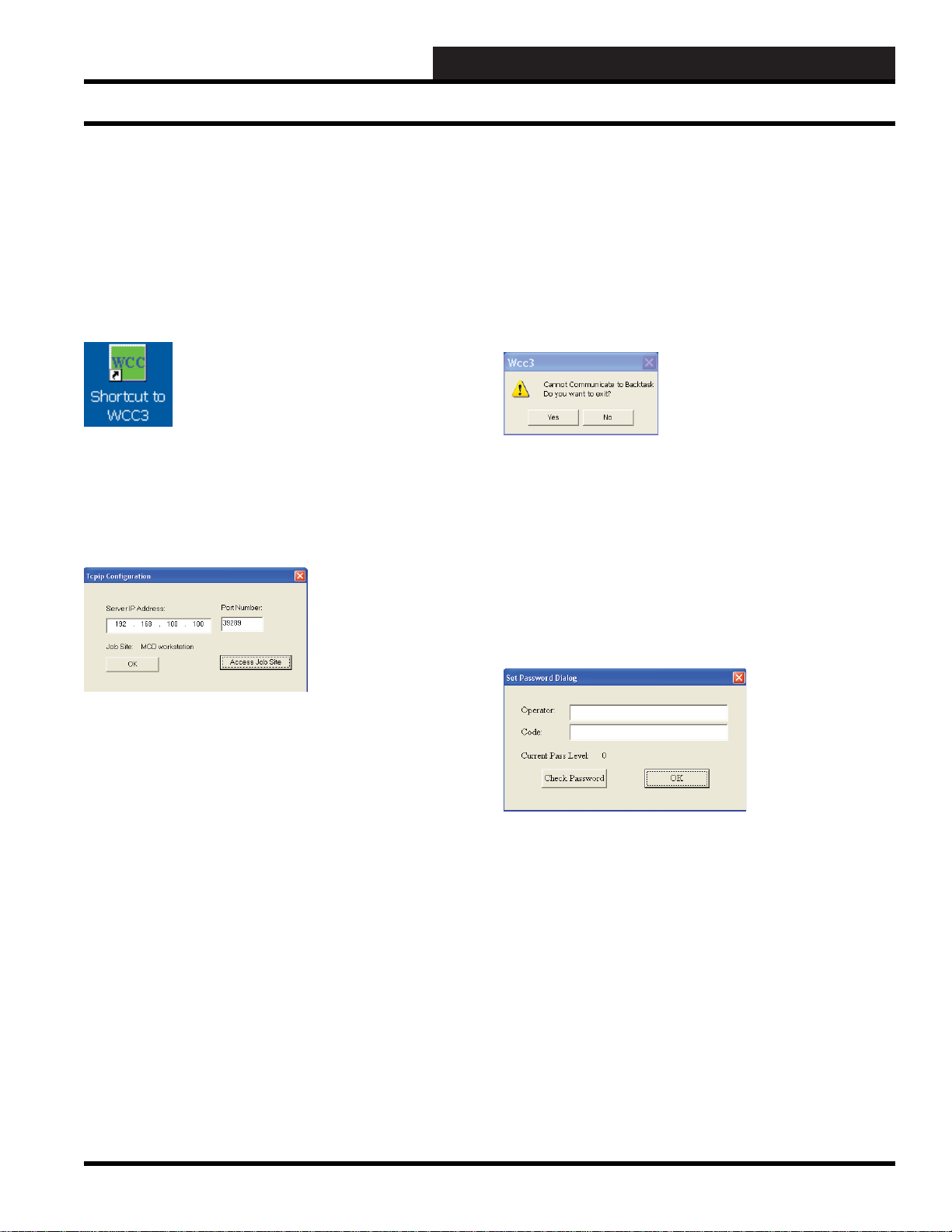
The WCC3.exe shortcut icon should have been
installed on your WCC III front end computer
desktop with the WCC III Installation Software
CD. The WCC III Installation Software CD is
W attMaster Controls Part # DM1WC011-01X.
T o start the WCC3.exe program, double-click the left mouse button
on the Shortcut Icon located on the Windows desktop.
After a short period of time, dependent upon the CPU speed of your
Windows based computer and the speed of your IP connection to
the internet, the WCC III T ype Connection Dialog Box will appear .
Using your mouse, left-click on the
The Remote Access Dialog Window will appear.
By selecting <OK>, the WCC3.exe program will now start to
connect to the selected WCC III – MCD via this selected IP address
connection. It should bring up the WCC III Set Password Dialog
screen within a new window. If the IP address connection fails to
connect to the WCC III – MCD, then another small dialog box
window will appear. This is the Cannot Communicate to Backtask
Dialog Box.
If you click <Yes>, you will exit the WCC3.exe program. You will
have to fi gure out why you cannot connect to the WCC III – MCD
via the IP address connection.
If you click
but instead you will be connected to the WCC III Main Menu.
This connection to the WCC III Main Menu is not an actual IP
connection, but rather a “dummy” WCC III main menu screen
window with no values. This “dummy” WCC III main menu
screen window will allow you to view and see what the actual
WCC3.exe screens will look like – minus any data.
<No>, you will not exit the WCC3.exe program,
<Access Job Site> button.
Server IP Address:
This is the static IP address of the WCC III – MCD. An IP Address
is like a phone number on the world wide web. The IP address for
the WCC III – MCD must be Static (does not change) as opposed
to Dynamic (constantly changing). This static IP address must be
provided by your internet service provider. (A static IP address
is the preferred IP connection method for the WCC III system to
function.) If you actually know the static IP address of the WCC
III – MCD that you wish to connect to, please enter it here in the
Server IP Address fi eld, or better yet, continue to the Remote Access
Dialog Window by selecting the
You can use a Dynamic IP Address with the WCC III – MCD,
but you must then have what is called a static “Host Name”. This
static “Host name” must then be provided by your internet service
provider and is limited to 58 total characters.
Port Number:
The WCC3.exe program opens a two-way , secure communications
port that then allows for communication between the WCC III –
MCD and the WCC3.exe program that is running on the WCC
III Front end computer. This IP Address connection is done on a
higher address port number than normal (WCC III connection is
port number 39289) to help reduce the risk of computer hacking.
<Access Job Site> button.
In the Set Password Dialog Screen enter an “Operator:”
identifi cation and a “Code:” or password equal to at least a pass
level 0 that has been previously set up on the WCCIII System
Parameter – Operator Code Screen. (See the Operator Code
Screen of the System Parameter Scr een in Section 3 for information
on setting up Operator Codes) Click
“Current Pass Level:” stays at 0 or higher (1, 2, or 3) then click
<OK>. By selecting <OK>, the WCC3.exe program will now start
to connect to the selected WCC III – MCD via this selected IP
address connection. It should bring up the WCC III Main Menu
within a new window. If the “Current Pass Level:” changes to
–1 then you do not have access to the WCCIII – MCD. If you
do not have access to the WCCIII – MCD and you click
then this connection to the WCC III Main Menu is not an actual IP
connection, but rather a “dummy” WCC III Main Menu window
with no values. This “dummy” WCC III Main Menu window will
allow you to view and see what the actual WCC3.exe screens will
look like – minus any data.
<Check Password>, if the
<OK>
WCC III Technical Guide
3-1
Page 6
WCC3.EXE SCREEN DESCRIPTIONS
Running the WCC3 Program
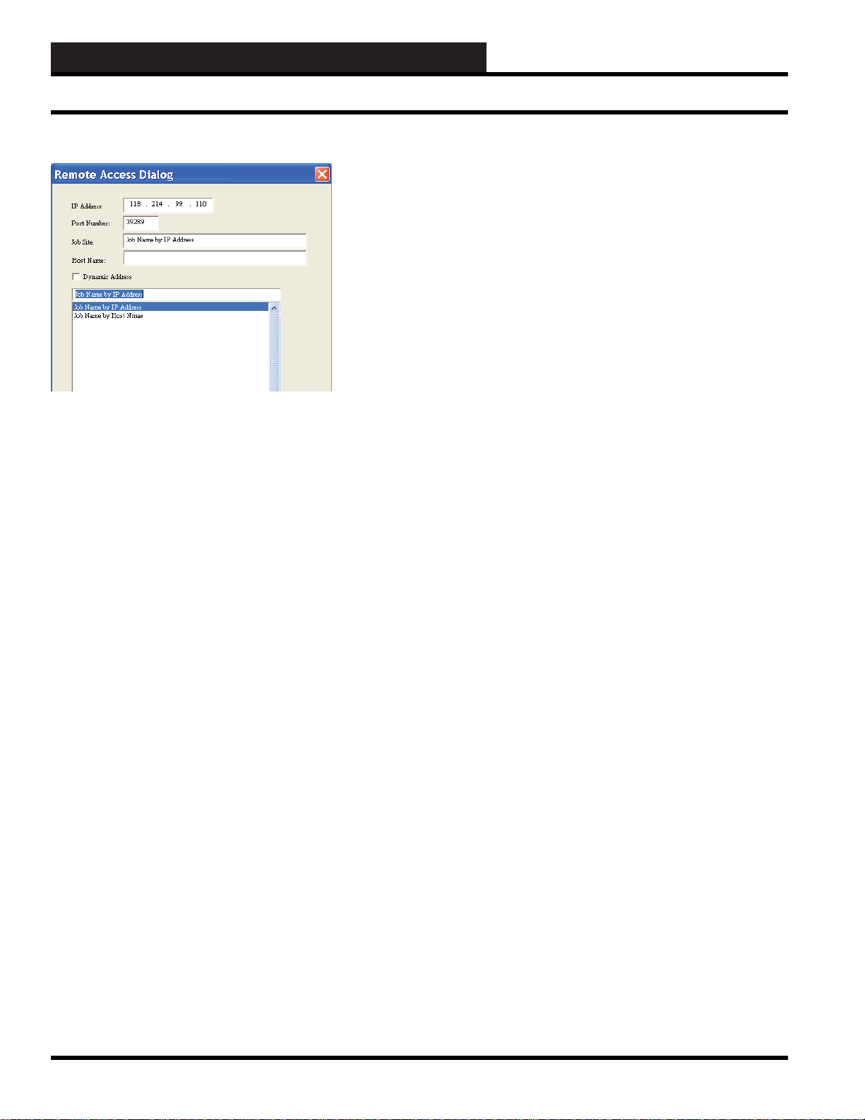
The Remote Access Dialog Box will allow you to enter multiple
WCC III – MCD IP addresses based upon “Job Site” names. This
is done by typing in the name of the jobsite you wish to call your
system.
First you must select a “BLANK” line in the bottom box area
with your left mouse button. (This line will then be highlighted
in “Blue”.) You must then enter a Job Site name in the “Job Site”
fi eld, along with the static IP address and Port number (39289) for
the WCC III – MCD that you wish to connect to with the WCC3.
exe program.
If you are using a static “Host Name” instead of a static IP address
please make sure that the Dynamic Address check box has been
selected, along with the static “Host Name” in the space provided.
As mentioned previously, you must get this static “Host Name”
from your internet service provider, and it is limited to 58 characters
total.
Please note that this “Job Site” name will also be the name of a
subdirectory that will automatically be created in the Local disk
C:\ProgramFiles\WCCIII\WCC3 subdirectory on the WCC III
Front end computer. The Remote Access Dialog Box also creates
a JobSite.dat data fi le in the C:\ProgramFiles\WCCIII\WCC3
subdirectory. This data fi le is not a viewable type of fi le. The
JobSite.dat fi le can be copied and then can be used on other WCC
III front end computers. This reused JobSite.dat will then recreate
the needed “Job Site” subdirectories on the other WCC III front
end computers upon the reselection of the Job Site IP address.
In an already fi lled out Remote Access Dialog Box, you can simply
select from the list of previously entered Job Sites that are displayed
in the bottom box fi eld. Then left-click
back to the Connection Dialog Box that was fi rst displayed. This
Connection Dialog Box now should have the desired IP address in
the Server IP Address location fi eld and the port number (39289)
in the Port Number location fi eld for the WCC III – MCD that you
wish to connect to with the WCC3.exe program.
<OK>. This will take you
IP Address:
This is the static IP address where the WCC III – MCD is located.
An IP Address is like a phone number on the world wide web.
The IP address for the WCC III – MCD must be static (does not
change) as opposed to Dynamic (constantly changing). This static
IP Address must be provided by your internet service provider.
(A static IP address is the preferred IP connection method for the
WCC III system to function.)
Port Number:
The WCC3.exe program opens a two-way , secure communications
port that then allows for communication between the WCC III –
MCD and the WCC3.exe program that is running on the WCC
III front end computer. This IP Address connection is done on a
higher address port number than normal (WCC III connection is
port number 39289) to help reduce the risk of computer hacking.
Job Site:
This is the name of the jobsite you wish to call your system. Please
note that this name will also be the name of a subdirectory that
will automatically be created in the Local disk C:\ProgramFiles\
WCCIII\WCC3 subdirectory.
Host Name:
You can use a Dynamic IP Address with the WCC III – MCD,
but you must then have what is called a static “Host Name”. This
static “Host name” must then be provided by your internet service
provider and is limited to 58 total characters.
When you have fi lled out all necessary fi elds, left-click
This will take you back to the Connection Dialog Box that was
fi rst displayed. This Connection Dialog Box now should have the
desired IP address in the Server IP Address location fi eld and the
port number (39289) in the Port Number location fi eld for the
WCC III – MCD that you wish to connect to with the WCC3.exe
program.
Left-click
was fi rst displayed. The Connection Dialog Box will have the
same IP address as listed originally before in the Server IP Address
location fi eld and the port number (39289) in the Port Number
location fi eld.
Left-click
Dialog Box to your Windows system default printer on the WCC
III front end computer. This print function is provided to give you
a hard paper backup copy of these IP address for the various WCC
III – MCD that you may have. This print function also creates a
Printscreen.dat data fi le in the C:\ProgramFiles\WCCIII\WCC3
subdirectory. This data fi le is not a viewable type of fi le.
<Cancel> to return to the Connection Dialog Box that
<Print> to send all of this data in this Remote Access
<OK>.
3-2
WCC III Technical Guide
Page 7
WCC III Main Menu T ool Bar
WCC3.EXE SCREEN DESCRIPTIONS
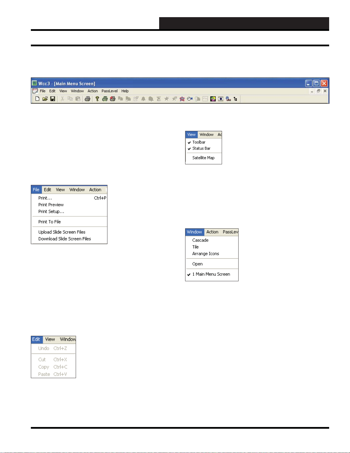
WCC III Main Menu T ool Bar
When you open the WCC III program and each of its available
screens, you will notice that the name of the screen will appear in
brackets at the top of the window, for example WCC III - [Main
Menu Screen]. Under that is what is referred to as the Top Menu
Bar. In the Top Menu Bar are the menus
<Window>, <Action>, <PassLevel>, and <Help>.
<File>, <Edit>, <View>,
File Menu
The <File> menu contains the functions <Print>, <Print Preview>
- preview your print job before printing, <Print Setup> - setup
your printer and printing options, <Print To File> - print to a fi le in
order to print the fi le at a later date, <Upload Slide Screen Files>
- saves all information for the Custom Screens and Bitmap Screens
on this WCCIII front end to the WCCIII – MCD,
Slide Screen Files> - downloads all information for the Custom
Screens and Bitmap Screens to this WCCIII front end from the
WCCIII – MCD.
<Download
Edit Menu
View Menu
The <View> menu gives you the option to show or hide the T oolbar
and Status Bar. A checkmark indicates Show. No checkmark
indicates Hide. You can also view the Satellite Map. If you choose
this option, the Satellite Map will appear on the screen. Press
<Esc> to return to the WCC III Main Menu.
Window Menu
The <Window> menu allows you to open more than one screen at
a time. Each screen is contained in its own window.
<Cascade> will arrange all windows into a stack, with each
window offset slightly. <Tile> will display all windows equally
without overlapping.
<Arrange Icons> - This function is not available at this time.
The <Edit> menu contains four functions; however, only <Copy>
and <Paste> are available for use. These functions work the same
as <Set Current Screen for Copying> and <Copy Screen From
Previous Screen>
located in the <Action> menu.
WCC III Technical Guide
<Open> - This function is not available at this time.
To activate a window, click the window title bar or choose the
name of the window in the
are numbered in the order they were opened.
<Window> menu. Multiple windows
3-3
Page 8
WCC3.EXE SCREEN DESCRIPTIONS
WCC III Main Menu T ool Bar
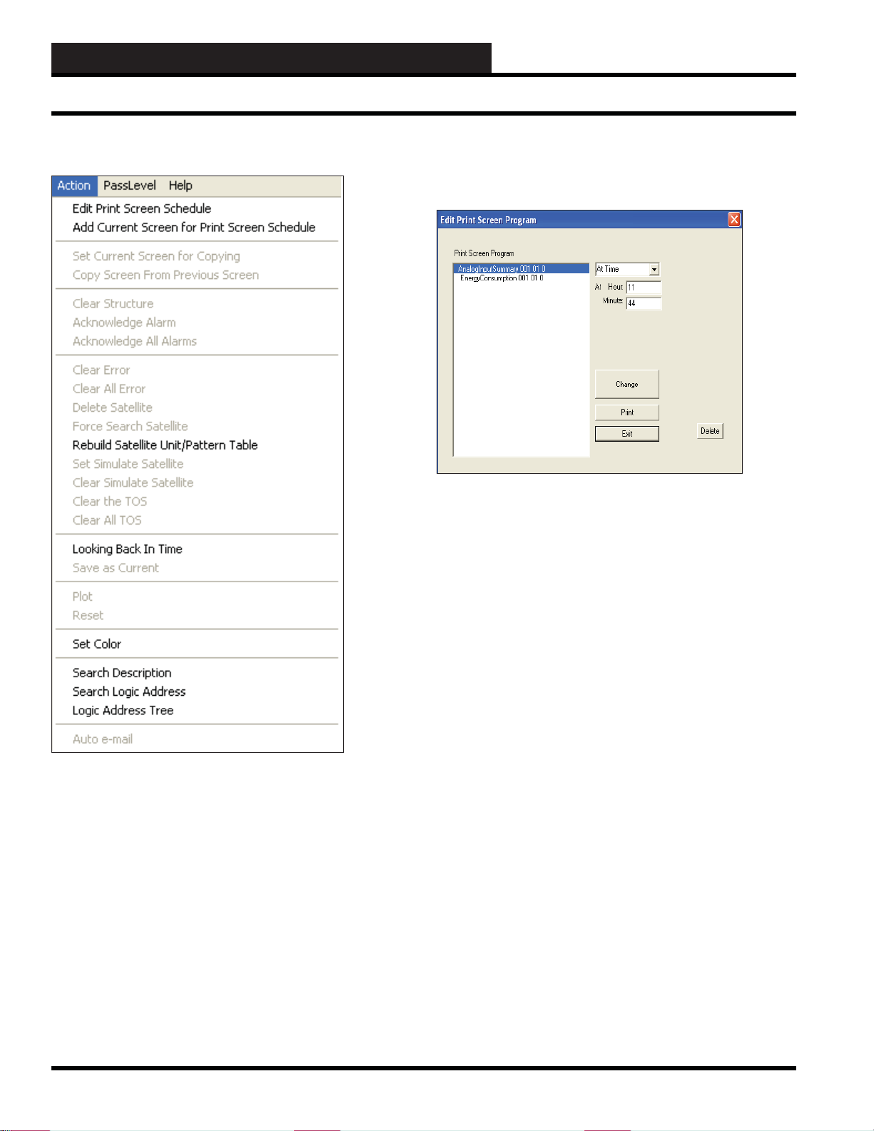
Action Menu
To set up the printing schedule for each screen, you must then
<Action>, <Edit Print Screen Schedule>. The Edit Print
select
Screen Pr ogram Window will pop-up.
You can select the printing schedule by time, interval, or global
binary.
If you select <At Time>, the At Hour: and Minute: fi elds will
appear. Enter the time of day with a two-digit hour value (military
time) and a two-digit minute value. The hour value should be less
than 24, and the minute value should be less than 60.
The <Action> menu has many functions. These functions’
availability are tied to individual screens. Available menu items
will be bolded.
Edit Print Screen Schedule/ Add Current
Screen
The fi rst two menu items <Edit Print Screen Schedule> and
<Add Current Scr een for Print Screen Schedule> are used to
automatically generate screen prints based on the schedule you set
up for each screen.
While in a screen, if you select
to Print Screen Schedule>, the screen will be immediately added
<Action>, <Add Current Screen
to the Print Screen Schedule Pr ogram.
If you select
<With Interval>, the Interval: fi eld will appear. Enter
the interval and select minutes, hours, or days from the drop down
menu. The interval should be less than 256 and greater than 0.
If you select
<Global Binary>, the Global Binary Number: fi eld
will appear. Enter a global binary number . If you wish to temporarily
remove the screen from the print schedule, select
<None> from the
drop down menu. The global binary value should be less than or
equal to 512 and greater than 0.
You must click
<Change> to have the system accept the assigned
schedule. If you wish to remove a screen from the schedule,
highlight the screen name and then click <Delete>. To print a
screen immediately, highlight the screen name and then click
<Print>
. Click <Exit> to exit the program.
Set Current Screen for Copying
To copy a set of data points from one satellite to the next, while
at the point you wish to copy from the current screen or within
the same satellite, select
Copying>.
<Action>,<Set Current Screen for
A message similar to the following will appear at the bottom of
the screen:
3-4
Point __ of Satellite __ was tagged for copy!
WCC III Technical Guide
Page 9
WCC3.EXE SCREEN DESCRIPTIONS
WCC III Main Menu T ool Bar
Copy Screen From Previous Screen
While at the Home position at the screen you wish to copy the data
to, select <Action>,<Copy Screen From Previous Screen>. The
data point will be copied from the previous screen to the current
screen.
Clear Structure
While at the Home position on the screen, select <Action>, <Clear
Structure> to clear/remove the data from the screen. This works
the same as pressing <Ctrl><Home>.
Acknowledge Alarm/Acknowledge All Alarms
Select <Action>,<Acknowledge Alarm> to acknowledge a
single alarm. Select
<Action>,<Acknowledge All Alarms> to
acknowledge all alarms on the Alarm Summary Screen.
NOTE: Acknowledge All Alarms only works with the Alarm
Summary Sc ree n.
Clear Error/Clear All Errors
While at the Satellite Summary Screen, select <Action>,<Clear
Error>
to clear an error located in the ERR column. You must
have the desired row highlighted in order to do this. Select
<Action>,<Clear All Errors> to clear all errors.
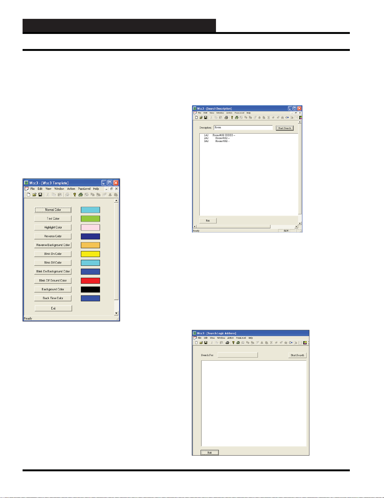
To rebuild all tables, type a zero in the Satellite Number fi eld
and select <Rebuild All Tables>. To rebuild one table, enter the
satellite number and then select
<Rebuild One T able>.
Set Simulate Satellite/Clear Simulate Sa tellite
While at the Satellite Summary Screen, highlight an empty satellite
entry and then select <Action>,<Set Simulate Satellite> to
create a simulated satellite. Select <Action>,<Clear Simulate
Satellite>
to reverse this process.
Clear the TOS/Clear all T OS
TOS stands for TUC off the system which means the satellite is no
longer communicating with the Wcc3 system. To clear the alarm
once communications are reestablished, do the following: While at
the Satellite Summary Screen, select
<Action>,<Clear the TOS>
or <Clear all TOS> to clear one or more TUCs that are off the
system.
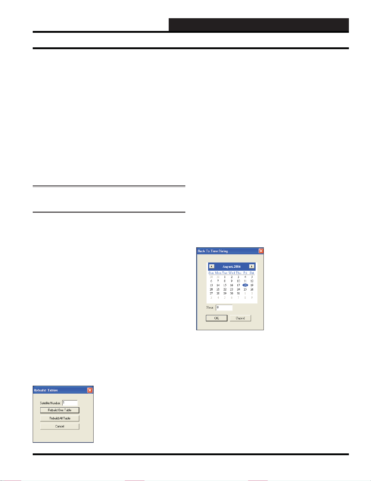
Looking Back in Time
You have the ability to view information for any month, day, and
year and time of day. The data is saved in the BACKTASK folder
on the hard drive. Select <Action>, <Looking Back in Time>.
The Back to Time Dialog Window will pop-up.
Delete Satellite
While at the Satellite Summary Screen, you can delete a satellite by
placing the cursor on the satellite you wish to delete and selecting
<Action>,<Delete Satellite>.
Force Search Satellite
While at the Satellite Summary Screen, you can search for a satellite
by placing the cursor at a satellite number you know to exist but is
lacking data, by selecting
<Action>,<Force Search Satellite>.
Rebuild Satellite Unit/P attern Table
While at the Satellite Summary Screen, you can rebuild satellite
tables by selecting
Table>. The following window will appear:
<Action>, <Rebuild Satellite Unit/Pattern
Use the arrow buttons at the top to move through months and years.
Select the day of the month by clicking on it. Type in the hour of
the day in two-digit military format. Then select <OK>.
The WCC III system will retrieve the data from the entered date
and time. To return to the current date and time, simply select
<Action>,<Looking Back in Time> again.
Save As Current
Once you retrieve data from the hard disk, you can save the data
to the satellite. This may be necessary if someone entered the
wrong data for a satellite, for example. To save the retrieved data
to the satellite as the current data, select
Current>.
<Action>, <Save As
WCC III Technical Guide
3-5
Page 10
WCC3.EXE SCREEN DESCRIPTIONS
WCC III Main Menu T ool Bar
Plot
When data is available to graph, for example, in the Trend Logs
screens, you can select <Action>,<Plot> and the data will be
plotted on a graph. This works the same as pressing
<Ctrl><G>.
Reset
While in the Trend Log screens, you can select <Action>,<Reset>
to reset the screen. This works the same as pressing <Ctrl><R>
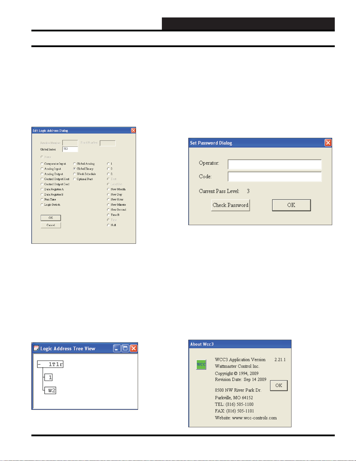
Set Color
At any time when running WCC III, you can change your screen
colors. Select
will appear:
<Action>,<Set Color> and the following window
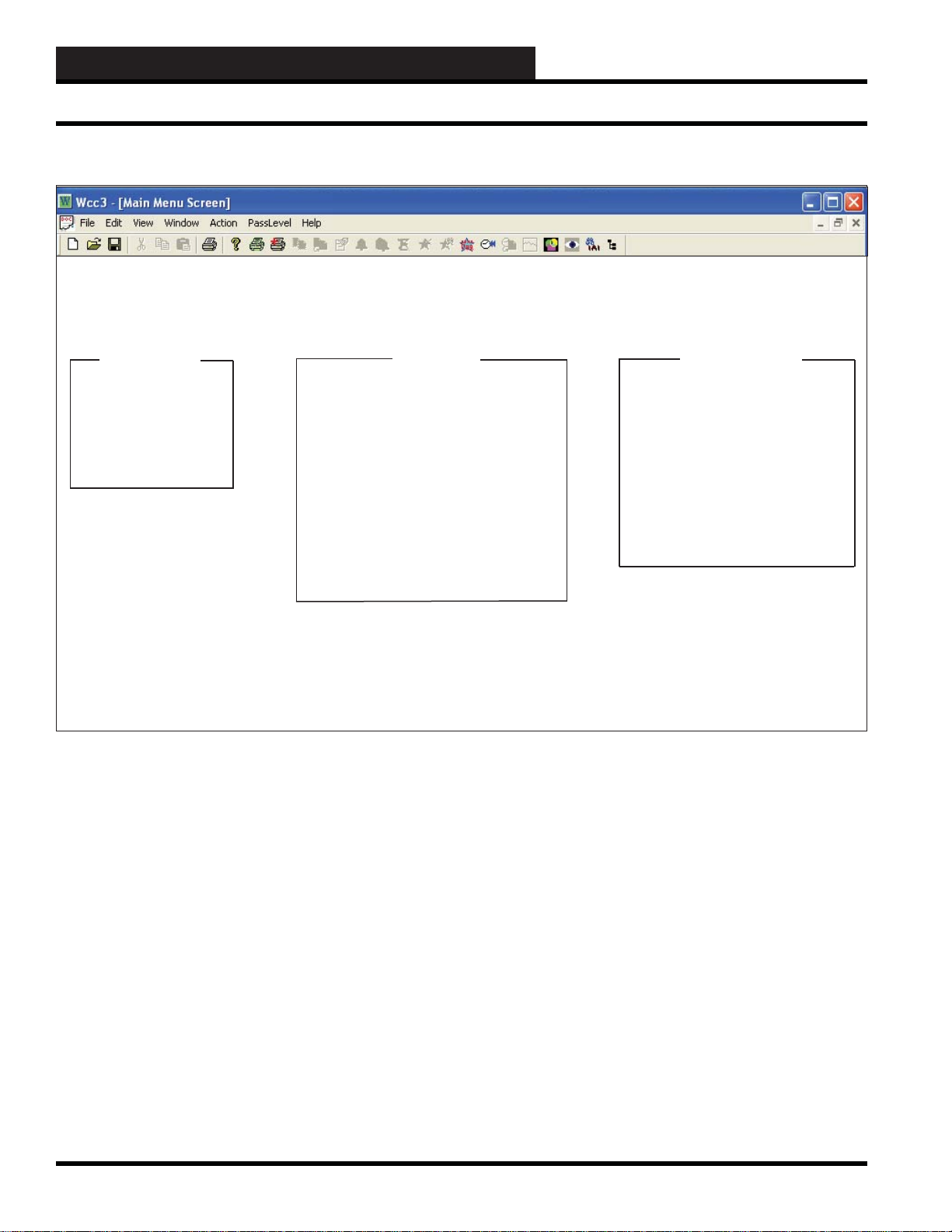
Search Description
At any time while running WCC III, you can search for a description.
Select
<Action>,<Search Description>. The following window
will appear:
Enter your description in the Description fi eld and then select
<Start Search>. The example in the window shows a search for
Room. When the Search is complete, double click on the result you
want to look at and its screen will appear. To return to the Sear ch
Description Screen, pr ess <Home>.
Search Logic Address
At any time while running WCC III, you can search for a logic
address. Select
Logic Address W indow will appear:
<Action>,<Search Logic Address>. The Search
3-6
WCC III Technical Guide
Page 11
WCC3.EXE SCREEN DESCRIPTIONS
WCC III Main Menu T ool Bar
When you click inside the Search For fi eld, the Edit Logic Address
Dialog Window will appear:
Y ou can select by Satellite Number and Point Number or by Global
Index and then select
Search For fi eld in the Search Logic Address Window. Then click
<Start Search>. When the Search is complete, double click on
the result you want to look at, and its screen will appear. To return
to the Search Logic Address Screen, press
<OK>. Your selection should appear in the
<Home>.
Auto E-mail
Auto e-mail enables/disables emails in the Backtask program. You
must be a Level 4 user to access this option.
PassLev el
The PassLevel is a quick way to change a person’s passcode
level. Select <PassLevel> from the Main Menu Toolbar. The Set
Password Dialog Box will appear:
Logic Address Tree
The Logic Address Tree allows you to see how the system
connects together. At any time while running WCC III, you can
select <Action>,<Logic Address Tree>. The Edit Logic Address
Dialog Window will appear. See window above.
You can select by Satellite Number and Point Number or by
Global Index and then select
the Logic Address Tree View Window.
Double-click the left mouse button to expand and collapse the tree.
Click the right mouse button to go to that data point’s screen.
<OK>. Your selection will appear in
Enter the Operator ID and Code. They will appear as asterisks
for security purposes. Click
password and display the designated level access.
You can also access this operation in the System Parameters
Screen.
<Check Password> to verify the
Help
The <Help> menu displays the About Wcc3 window which
contains the version number of the software along with W attMaster
Control’s company information. It is important to know the version
number when calling WattMaster Control’s Technical Support.
Select
<OK> to exit the window.
WCC III Technical Guide
3-7
Page 12

WCC3.EXE SCREEN DESCRIPTIONS
Special Purpose Keys
Special Purpose Keys
The special purpose keys are a very powerful and necessary part of
the WCC III system, but they can also be very dangerous if you are
not sure how to use them. Therefore, most of the special purpose
keys require that the operator have a Level 3 passcode.
<Ctrl><A>: Acknowledge Alarms—Used at the Analog
Input Summary Screen, Trend Log Run Time Scr een, Alarm
Summary Screen, and Global Analog/Binary Summary Screen.
<Ctrl><G>: Display Graphs—Used at the Analog T rend
Screen, Pr oportional Reset Screen, and the Look-up T able
Screen to plot data.
<Ctrl><K>: Clear Communication Errors—Used at
Satellite Summary Screen for troubleshooting, clears
communication errors on a single satellite.
<Ctrl><R>: Manually Reset (Clear) Data—Used at the
Trend Log Screen, Global Analog Integral Mode to reset
accumulated consumption, Energy Consumption Screen to
reset consumption.
< Ctrl><Home>: Clear Input Data from Present Screen
(clear structure)—Cursor must be in the Home position on the
screen.
<Ctrl><U> Toggle Updating—Used on Custom Screens and
Bitmap Screens to “freeze/unfreeze” the data being displayed.
<Ctrl><A>: Acknowledge Alarms
When an alarm occurs within the system, the alarm condition
appears on its respective summary screen as a fl ashing display
generally on the right side of the screen. Once the alarm has been
acknowledged, one of two possible conditions will be displayed.
The fi rst condition is when an alarm is acknowledged, but the
alarm remains outside of the alarm limits. When this happens, the
alarm information is still displayed on the screen, but it appears
solid instead of blinking. The second condition is when an alarm
is acknowledged AND the alarm is inside the alarm limits. In
this case, all alarm information for that point is cleared from the
screen.
To acknowledge new (blinking) alarms, position the cursor (>)
at the point for which you wish to acknowledge alarms. Once
positioned, press and hold
<Ctrl>, then press <A>, and then release
both keys at the same time.
<Ctrl><G>: Display Graphs
The WCC III system has graphs for the Analog Trend Screen, the
Proportional Reset Scr een, and the Look-Up Table Scr een that can
be displayed on the screen and can be printed on the printer using
the
<File>, <Print> command.
The graph for the Analog Trend - T rend Logging Scr een is accessed
while the cursor is at the Home position of an Analog Trend Scr een.
Press <Ctrl><G>. Press the <Home> key to return to the Analog
Trend Screen.
<Ctrl><F> Find Logic Address—Used on Custom Screens
and Bitmap Screens to fi nd the exact location where a point
was placed on the screen.
<Ctrl><D> Delete Logic Address—Used on Custom
Screens and Bitmap Screens to delete the location where a
point was placed on the screen.
3-8
The Proportional Reset Screen also has a graph that can be
accessed by pressing
<Ctrl><G> while the cursor is anywhere on
the Proportional Reset Screen. Press the <Home> key to return to
the Proportional Reset Scr een.
To access the graph for the Look-Up Tables (GA 121-128), while
the cursor is at any position on a Global Analog Look-Up Table,
press
<Ctrl><G> to display the Look-Up Table graph. Press the
<Home> key to return to the Global Analog Look-Up Table.
WCC III Technical Guide
Page 13

WCC3.EXE SCREEN DESCRIPTIONS
Special Purpose Keys
<Ctrl><K>: Clear Communication Errors
The WCC III system keeps track of the transmission and receive
errors between the MCD Internet appliance and the satellite
controllers on the Satellite Summary Screen. The <Ctrl><K>
feature clears the existing number of errors and is used for troubleshooting purposes.
<Ctrl><R>: Reset Trend Logs or Global Analog
Accumulation Screens
When you are at a Trend Logging Screen and wish to reset (clear)
the existing trend log data on the particular screen, simply press
<Ctrl><R>. This should automatically reset (clear) the data on the
Trend Log Scr een. On new systems, the Trend Log Screens should
be reset before they have been programmed to clear out any “bad
data” that might be in the satellite controller.
The
<Ctrl><R> feature is also used to reset the global analogs
using the integral mode and the Energy Consumption Scr een.
If the system is trying to e-mail-out an alarm and it cannot report
its information for some reason, the system will continue to try and
e-mail the call-out forever unless you press
<Ctrl><R> while the
cursor is at the “Disabled by” position for that alarm type on the
System Parameters Screen.
<Ctrl><Home>: Clear Input Data from Present Screen
You must be a Level 3 user for <Ctrl><Home> to work. <Each
screen (or point) has data which is saved in the memory of the
MCD or the satellite controller. Before any processing of the data
entered on a screen is performed, the system checks the point’s
“structure valid” indicator to insure that the data it contains is valid
and properly formed. If the point is not valid, then that point is
skipped and processing continues with the next point. In addition,
all summary data is removed from that point’s summary screen.
T o clear a screen (invalidate it), the cursor must be in the “Home”
position on the individual screen that is to be cleared. Once there,
press
<Ctrl><Home>. The data on the screen should be cleared
away. Once you have cleared a point, the data for that point is lost,
and it cannot be recovered. Therefore, make sure you have the
right point before using
<Ctrl-U>: Toggle Updating
<Ctrl><Home>.
The values of the WCC III points on the Custom Screen are
“dynamic.” That is, the values on the screen will change as the
value of the point changes. However, you have the option of
“freezing” the points at their present value by pressing
<Ctrl>
and <U> while the Custom Screen is displayed on the monitor. To
return to “live” data, press
<Ctrl> and <U> again.
<Ctrl-F> and <Ctrl-D>: Delete a Point Address on the
Custom Screen
To delete a point on the Custom Screen, fi rst you must have the
cursor in the exact location it was when the point was placed
on the screen. To simplify fi nding this location, you may move
the cursor near the existing point and then press <Ctrl> and <F>
simultaneously to cause the cursor to move to the exact position
where the point was created. You may delete the point by pr essing
<Ctrl> and <D> simultaneously, and then pr essing <Enter>. The
four slashes (////) will then appear. You may enter a new point, or to
remove the slashes, leave the screen by pressing <Home> twice,
and then re-access the screen.
WCC III Technical Guide
3-9
Page 14
WCC3.EXE SCREEN DESCRIPTIONS
Main Menu Screen
MAIN MENU SCREEN
----------------------------------------------------------------------------------------------------------------------------------------------------------------------
08:11 1/20
WATTMASTER CONTROL CENTER III
WCC III
Sat #____ Overview Central Unit
Analog Input Alarm Summary PID Programs
Control Output Satellite Summary Week Schedules
Analog Output Overrides Optimal Starts
Trend Logs Holidays Analog Globals
Logic Switches System Parameters Binary Globals
Binary Output On/Off/Units Messages Shed/Restore Programs
Alarm Messages Duty Cycle Programs
Secure the System Proportional Programs
Energy Consumption Tenant Override
Custom Screens General Message
Bitmap Screens
Network Information
Active alarms in classes: 16
WCC III Version 2.21
BACKTASK Version 2.18 L
The Main Menu Screen allows you to view the available screens
within the WCC III system. To get to a screen listed on the Main
Menu, use the arrow keys to position the cursor over the name of
the screen you want to access and press <Enter>.
The Main Menu is divided into three categories: Sat #, Overview,
and Central Unit.
Sat #____
The information associated with the screens within this category is
stored in the satellite controllers and IS NOT stored in the MCD.
It is a very good idea to save this information on a back-up disk
by using the Satellite Save/Restore program located in the WCC
Utility Program.
Overview
This section allows the operator to perform operations and view
screens which affect all of the satellite controllers on the system.
The information associated with the screens located in this
category is stored in the MCD. When the screens in this category
are programmed for the fi rst time, or when a change is made to
these screens, the system automatically stores the information on
the data disk.
Central Unit
The screens located in this category are GLOBAL commands.
Global commands “travel” along the two-wire communication
loop and are used by any or all of the satellite controllers. All of
the satellites are constantly monitoring this information but only
certain satellites will react to the information depending on how
they have been programmed. The information associated with the
screens located in this category is stored in the MCD. When the
screens in this category are programmed for the fi rst time or when
a change is made to these screens, the system automatically stores
the information on the hard drive disk.
3-10
WCC III Technical Guide
Page 15

WCC3.EXE SCREEN DESCRIPTIONS
Active alarms in classes:
If an alarm is active within the system, the alarm type number will
appear at this location. You will need to go to the Alarm Summary
Screen to locate the specifi c alarm.
If the alarm is highlighted, it has not been acknowledged. If the
number is not highlighted, all of the alarms in that class have been
acknowledged.
WCC III Version _.__
BACKTASK Version _.__
The version number of the software presently being used by the
WCC III system will appear at these locations. Backtask is a
portion of the WCC III software. Each version of the WCC III
software operates with a specifi c version of Backtask. This has
been added to insure that the right version of Backtask is operating
with the WCC III software.
Main Menu Screen
WCC III Technical Guide
3-11
Page 16

WCC3.EXE SCREEN DESCRIPTIONS
Analog Input Summary Screen
Analog Input Screen’s WCC III Logical Address is XXXAY, where XXX = Satellite Address, A = Analog Input, and Y = 1-8
ANALOG INPUT SUMMAR Y SCREEN
-----------------------------------------------------------------------------------------
Analog Inputs Satellite 1 S1-KC Time Date
Analog Inputs 08:22 01/20
Description Current Value Alarm Limits Stat Mode Alarm Details
A1: S1-A1 50.0 Deg F 65.0 80.0 ON
A2: S1-A2 0 Deg F 45.0 65.0 OFF
A3: S1-A3 0 Deg F -10.0 100.0 ON
A4: S1-A4 0 Deg F 45.0 100.0 ON
A5: S1-A5
A6: S1-A6
A7: S1-A7 9.0 Deg F
A8: S1-A8 99.0 Deg F
C1: OFF
C2: OFF
C3: OFF
C4: OFF
C5: OFF
C6: OFF
C7: OFF
C8: OFF
HOME for menu
An analog input is a signal sent to the satellite controller that can
be represented by a number such as temperature, pressure, etc.
The Analog Input Screen is used to “tell” the WCC III system the
characteristics of the sensor and to set alarm limits. The “Binary
Setpoint” option at the bottom of the Analog Input Screen can be
used to convert the analog input to a binary (On/Off) input.
Analog Inputs
Specifi es the summary type to be displayed. Because this is a
“choice” fi eld, the list of available choices will be displayed at the
bottom of the screen:
<Analog Input, Control Output, Analog Output,
Trend Logging, Logic Switch, Binary Output>
Y ou can access one of the screens which appear in this choice fi eld
without returning to the Main Menu by pressing the
until the desired summary type has been selected and then pressing
<Enter>.
<space bar>
Satellite______
Specifi es the number of the satellite which you are currently
communicating with. If you would like to view the analog input
summary data for a different satellite, use the arrow keys to move
the cursor to this fi eld, enter the desired satellite number, and press
<Enter>. 1 to 239.
T o view or edit a specifi c analog input, use the arrow keys to move
the cursor (shown as “>” along the left-hand side of the screen) to
the desired point and press <Enter>. The Analog Input Screen for
the specifi ed point will now appear.
Time / Date
The present time and date will automatically appear at these
locations.
Description:_______________
The description message which was entered on the Analog Input
Screen is displayed here to help you identify the different analog
inputs within the system.
3-12
WCC III Technical Guide
Page 17

WCC3.EXE SCREEN DESCRIPTIONS
Analog Input Summary Screen
Current Value
The current value of the analog input is automatically displayed
here.
Alarm Limits
The alarm limits which were input on the Analog Input Screens
will automatically be displayed here.
Stat
The present “ON” or “OFF” status of the binary input which is
controlling the schedule for the alarm limits is shown here. For
example, if week schedule #1 (W1) has been input to control
the schedule of the alarm limits, the message “ON” will appear
here when week schedule #1 is “ON” and “OFF” will appear
when week schedule #1 is “OFF”. When W1 is “ON” the “On
Schedule” alarm limits will be active, and when W1 if “OFF” the
Off Schedule” alarm limits will be active.
Mode
The “alt” message will appear here when the alternate alarm limits
are active. When the input value which has been entered on the
Analog Input Screen to select the alternate alarm limits is “ON,”
the WCC III system will use the “Alternate Alarm Limits” and the
“alt” message will be displayed here.
Alarm Details
This location will automatically display the alarm message, the
high or low value of the analog input, and the time and date of the
occurrence of the peak value.
When an alarm occurs, the alarm message will blink on the screen.
To acknowledge an alarm, position the cursor at the point for
which you wish to acknowledge the alarm. Then press
or left-click on <Action> to bring up the <Action> menu at which
point you can select <Acknowledge Alarm> or <Acknowledge
All Alarms>.
NOTE: The <Acknowledge All Alarms> option will
only work on the Alarm Summary Screen.
<Alt><A>
At this point, one of two things should happen. If the value of
the analog input is presently within the alarm limits, the message
will disappear. If the value of the analog input is not within the
alarm limits, the message will stay on the screen, but it will quit
blinking.
WCC III Technical Guide
3-13
Page 18

WCC3.EXE SCREEN DESCRIPTIONS
Analog Input General Screen
Analog Input Screen’s WCC III Logical Address is XXXAY, where XXX = Satellite Address, A = Analog Input, and Y = 1-8
ANALOG INPUT GENERAL SCREEN
Satellite # 1 ANALOG INPUT # 1
Description: RM101 Type: Analog General
Pattern for values associated with this input: xxx.x
Units @ 0% scale: 0.0 DEG. Units of Measure message #: 1
@ full scale: 100.0 DEG. Filter time constant: 8 seconds
ALARMS
Controlled by: W1 Limits Low High
Alarm Type: 1 On 65.0 80.0 DEG.
Alarm Message #’s: Low 2 High 1 Off 50.0 100.0 DEG.
Alternate limits selected by: .... On (alt) 0.0 0.0 DEG.
Off (alt) 0.0 0.0 DEG.
Limit overlap time
after control change: 20 minutes Local set 55.0 90.0 DEG.
BINARY SETPOINT
OFF Above 0.0 DEG. On Message #: 0
OFF Below 0.0 DEG. Off Message #: 0
HOME for menu
Satellite # _______
Specifi es the number of the satellite which you are currently
editing. If you would like to edit a different satellite, use the arrow
keys to move the cursor to this fi eld, type in the desired satellite
number, and press
Analog Input # ________
This “fi eld” actually contains two separate fi elds. The fi rst fi eld
specifi es the point “type” (i.e., analog input, control output, analog
output, etc.) and displays the current type in textual form. Because
this is a “choice” fi eld, the list of available choices will be displayed
at the bottom of the screen:
<ANALOG INPUT, CONTROL OUTPUT, ANALOG OUTPUT,
TREND LOGGING, LOGIC SWITCH, BINARY OUTPUT>
You may make your selection by pressing the <space bar> until
the desired choice appears and then pressing <Enter>. (If you select
a point type that is different than that currently being displayed, the
screen will be rewritten with the appropriate screen and data.)
<Enter>.
Additionally, this fi eld specifi es the point number to edit. For the
Analog Input Screen, this number can range from one to eight,
corresponding from A1 to A8, respectively. If you would like to
edit a different point, move the cursor to this fi eld by using the
arrow keys, enter the desired point number, and press
Description:
A short message is entered here which is displayed on Summary
Screens to help you remember points within the system. You may
enter up to ten characters (control codes, ALT codes, and the double
quote character are not allowed).
Type: Analog General
This fi eld is automatically fi lled in by the system. On screens 2-8,
this will always read “ANALOG.” On screen number 1, it will
read either “ANALOG” or “PULSE” depending on the position of
the pulse switch on the satellite controller.
<Enter>.
3-14
WCC III Technical Guide
Page 19

WCC3.EXE SCREEN DESCRIPTIONS
Analog Input General Screen
Sensor Type
This is a choice fi eld for Analog types only. A list of available
choices will be displayed at the bottom of the screen:
<General, Thermistor, Resistor,
Resistor+, RawCount, Thermistor+>
You may make your selection by pressing the <space bar> until
the desired Analog Type has been selected and then pressing
<Enter>.
General = A general use user programmable analog input screen.
Pulse = Specifi es the calibration information for the pulse meter
connected to channel 1 of the satellite controller.
Thermistor = Used to setup WattMaster 10K type 3 curve
thermistors.
Resistor = Used to measure resistance of a variable potentiometer.
Resistor+ = Used to setup different types of thermistors.
WattMaster thermistors are 10K type 3 curve. You would enter
values on the screen to correspond to different values and type
curves of thermistors.
RawCount = Is the raw count value straight from the 12 bit A to D
converter. Used for testing and or calibrating to see if the analog
signal is linear, so that you may test the non-linear curve of any
sensor to determine if any offset is needed.
Thermistor+ = T o be used if you are using a thermistor type sensor
that WattMaster Controls has not provided. Other thermistor type
sensors can be connected to the Satellite controller’s analog inputs
with this screen. Please consult the WattMaster Controls factory
for all other thermistor type sensors that you wish to connect to the
Satellite Controller. WattMaster Controls can provide the correct
b0, b1, b3 values at our option.
Pattern for Values Associated With This Input:
Specifi es where you would like the decimal point to appear in the
value displayed by the system. Because this is a “choice” fi eld,
a list of available choices will be displayed at the bottom of the
screen:
< x,xxx , xxx.x , xx.xx , x.xxx >
You may make your selection by pressing the <space bar>
until the desired data pattern has been selected and then pressing
<Enter>.
Units @ 0% scale:
@ Full scale:
If the screen type is “ANALOG,” this specifi es the scaling
information used by the system to proportionally scale the input
value to the desired range. The raw input value to the satellite
controller ranges from zero to one volt. If the scaling information
has been set to 0 at 0% scale, and 100 at Full scale, a raw input
value of 0.6 volts would produce a scaled value of 60.
If the screen type is “PULSE,” this specifi es the calibration
information for the pulse meter connected to channel 1 of the
satellite controller. The fi rst input is a “choice” fi eld, and therefore
a list of available choices will be displayed at the bottom of the
screen.
_______ Pulses = _______ Hours
< 100, 1000 >
The second input is used to “scale” or “calibrate” the particular
sensor that is being used. For example, consider a pulse meter
which measures the kwh of a building. Electrical meters are
basically a small motor whose speed is proportional to power
being used. Let’s consider a meter where one revolution equals
one kwh, and the meter sends 5 pulses to the satellite controller for
every 6 revolutions. Therefore, we would enter “100 Pulses = 120
kwh Hours.” (NOTE: maximum pulse rate allowed = 4 pulses per
second.)
5 pulses = 6 revolutions
1 revolution = 1 kwh
5 pulses = 6 kwh
100 pulses = 120 kwh
Units of Measure Message #: 1
A number is entered here that references a message on the On/Off
Units Messages Screen. For example, if units-of-measure message
#1 is “Deg F,” entering “1” will cause “Deg F” to be displayed as
the units-of-measure for the analog input.
Filter Time Constant: ____ Seconds
Specifi es the sampling rate of the analog input. This is used by the
satellites to “fi lter” (or smooth) the analog input signal. This can be
used on inputs that “jump around” to reduce sporadic load control.
Because this is a “choice” fi eld, the list of available choices will be
displayed at the bottom of the screen:
< 0, 1, 2, 4, 8, 16, 32, 64 >
You may make your selection by pressing the <space bar> until
the desired fi lter time constant has been selected and then pressing
<Enter>.
WCC III Technical Guide
3-15
Page 20

WCC3.EXE SCREEN DESCRIPTIONS
Analog Input General Screen
------ALARMS------
Controlled by:
Specifi es the binary value that selects the ON or OFF alarm limits.
When this value is OFF , the OFF alarm limits are selected; when it
is ON, the ON alarm limits are selected.
Alarm Type:
Specifi es the priority (or “importance”) level for any alarms
generated by this input. Alarm types range from one (highest
priority) to eight (lowest priority). The system displays and e-mails
higher priority alarms fi rst. (The fi rst fi ve alarm priorities (1-5)
have e-mail-out-on-alarm capabilities.)
Alarm Message # Low: ___ High: ___
Specifi es a pair of message numbers, one for LOW alarms and
the second for any HIGH alarms. These numbers are used by
the system to reference a message which is entered on the Alarm
Message Screen.
Alternate Limits Selected By:
Specifi es the point that initiates the Alternate mode. When this
address is zero (or OFF), the Normal alarm limits are selected;
when it is one (or ON), the Alternate alarm limits are selected.
Limits Low High
On _____ _____ °. F
Off _____ _____ °. F
On (alt) _____ _____ °. F
Off (alt) _____ _____ °. F
Local Set _____ _____ °. F
There are two fi elds on this screen that determine which set of
limits are active—the status of the “Controlled by” fi eld and the
status of the “Alternate Limits selected by” fi eld. When the value
that has been input in the “Controlled by” fi eld is ON, either the
“On” limits or the “On (Alt)” limits are active depending on the
status of the value input in the “Alternate Limits selected by” fi eld.
If the value in the “Alternate” fi eld is On, the “On (Alt)” limits are
used, and when the “Alternate” value is OFF, the “On” limits are
used.
Alternate Limits Active Alarm
Controlled by: Selected by: Limits:
On Off On
On On On (Alt)
Off Off Off
Off On Off (Alt)
The local set alarm limits become active if the MCD quits
communicating with the satellite controller. After communications
are re-established, any alarms that occurred while the satellite was
in local set will be reported.
Limit overlap time after control change:
This specifi es the amount of time the WCC software will wait after
a control change (i.e., on/off schedule, alternate mode, local set
mode) before deciding to generate an alarm. The fi rst input is a
user-entered number from 1 to 60, and the second input is either
seconds or minutes. This second input is a “choice” fi eld; the list
of available choices will be displayed at the bottom of the screen:
<Seconds, Minutes>
This group of inputs specifi es the alarm limits for the “Normal,”
“Alternate,” and “Local Set” modes. Each mode has a LOW and
HIGH limit. When the value of the analog input goes out of these
limits, an alarm is generated, and the alarm will automatically
display and e-mail out.
3-16
WCC III Technical Guide
Page 21

WCC3.EXE SCREEN DESCRIPTIONS
Analog Input General Screen
------ BINARY SETPOINTS ------
____Above:____
____Below:____
These inputs are used to convert the analog signal to a binary (On/
Off) signal. The value that is going ON and OFF is a software point
referred to as a comparator. Each analog input has a comparator
associated with it named “Cn.” The comparator for analog input #1
is “C1,” analog input number 2 is “C2,” and so on. The status of the
comparator can be seen on the Analog Input Summary Screen.
When the
user has
selected:
OFF Above &
OFF Below:
OFF Above &
ON Below:
ON Above &
OFF Below:
ON Above &
ON Below:
The value of the comparator is:
OFF when the Analog Input value is greater than the
ABOVE setpoint or less than the BELOW setpoint,
and ON when the Analog Input value is equal to
either one or between the two setpoints.
OFF when the Analog Input value is greater than
or equal to the ABOVE setpoint or until the Analog
Input value becomes less than the BELOW setpoint,
and ON when the Analog Input value is less than or
equal to BELOW setpoint or until the Analog Input
value becomes greater than the ABOVE setpoint.
OFF when the Analog Input value is less than or
equal to the BELOW setpoint or until the Analog
Input value becomes greater than the ABOVE
setpoint, and ON when the Analog Input value is
greater than or equal to the ABOVE setpoint or
until the Analog Input value becomes less than the
BELOW setpoint.
OFF when the Analog input value is equal to either
one or between the two setpoints, and ON when
the Analog Input value is greater than the ABOVE
setpoint or less than the BELOW setpoint.
Because this is a “choice” fi eld, a list of available choices will be
displayed at the bottom of the screen:
<ON, OFF>
You may make your selection by pressing the <space bar> until
the desired choice is selected and then pressing <Enter>.
On Message #:
Off Message #:
Specifi es a pair of message numbers, the fi rst for the ON state and
the second for the OFF state of the comparator. These numbers
are used by the system to reference a message on the ON/OFF
Units Message Screen. For example, the comparator might be set
up to come on when the outside air temperature is below 55 °F for
economizer operation. Set up the On/Off Message Screen so that
message #3 is “ECON” and message #4 is “REFRIG.” The “On
Message” number would be “3” (ECON), and the “OFF Message”
number would be “4” (REFRIG).
WCC III Technical Guide
3-17
Page 22
WCC3.EXE SCREEN DESCRIPTIONS
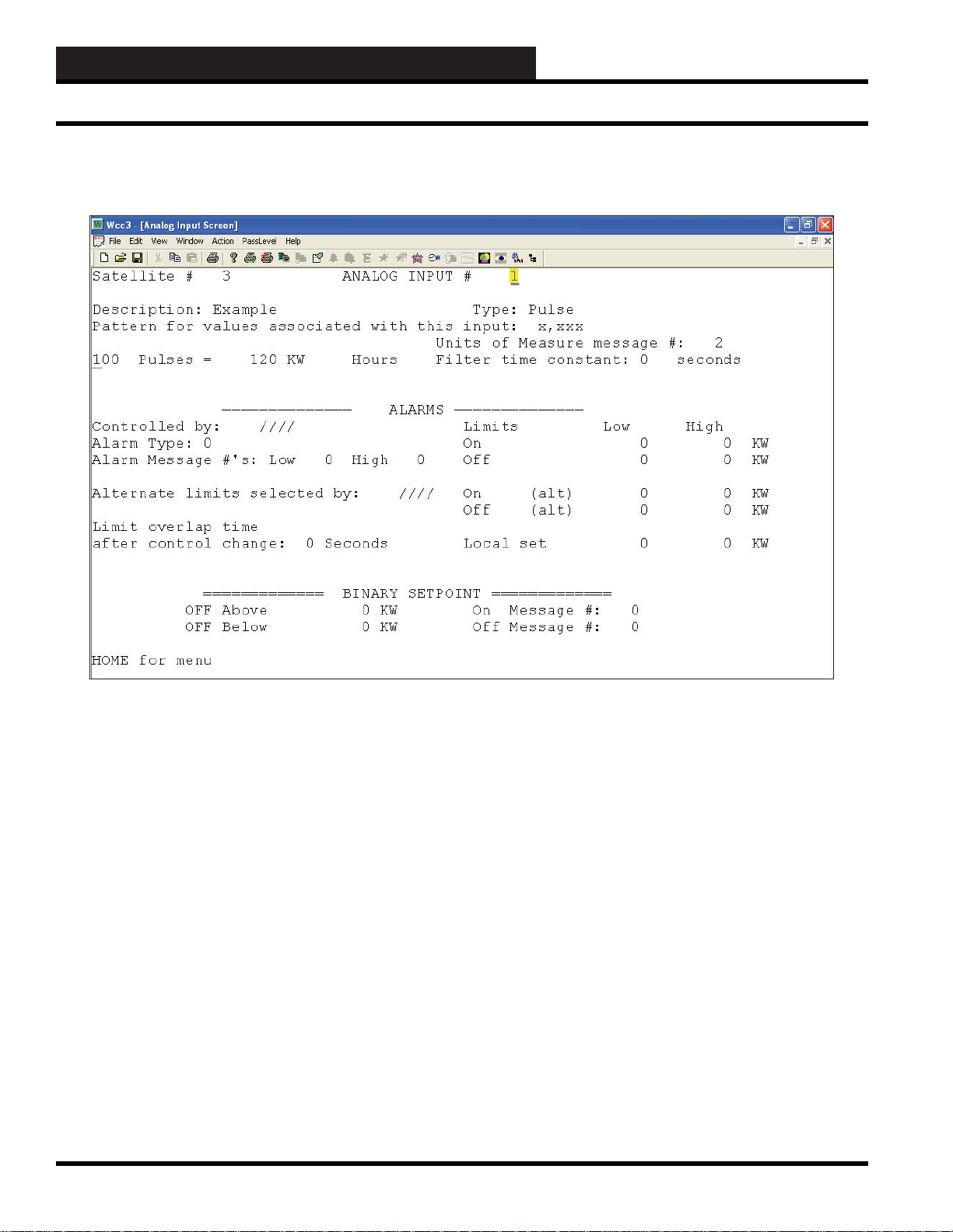
Analog Input Pulse Screen
Analog Input Screen’s WCC III Logical Address is XXXAY, where XXX = Satellite Address, A = Analog Input, and Y = 1-8
ANALOG INPUT PULSE SCREEN
Satellite # _______
Specifi es the number of the satellite which you are currently
editing. If you would like to edit a different satellite, use the arrow
keys to move the cursor to this fi eld, type in the desired satellite
number, and press
Analog Input # ________
This “fi eld” actually contains two separate fi elds. The fi rst fi eld
specifi es the point “type” (i.e., analog input, control output, analog
output, etc.) and displays the current type in textual form. Because
this is a “choice” fi eld, the list of available choices will be displayed
at the bottom of the screen:
<ANALOG INPUT, CONTROL OUTPUT, ANALOG OUTPUT,
TREND LOGGING, LOGIC SWITCH, BINARY OUTPUT>
You may make your selection by pressing the <space bar> until
the desired choice appears and then pressing <Enter>. (If you select
a point type that is different than that currently being displayed, the
screen will be rewritten with the appropriate screen and data.)
<Enter>.
Additionally, this fi eld specifi es the point number to edit. For the
Analog Input Screen, this number can range from one to eight,
corresponding from A1 to A8, respectively. If you would like to
edit a different point, move the cursor to this fi eld by using the
arrow keys, enter the desired point number, and press
Description:
A short message is entered here which is displayed on Summary
Screens to help you remember points within the system. You
may enter up to ten characters (control codes, ALT codes, and the
double quote character are not allowed).
Type: Pulse
This fi eld is automatically fi lled in by the system. On screens 2-8,
this will always read “ANALOG.” On screen number 1, it will
read either “ANALOG” or “PULSE” depending on the position
of the pulse switch on the satellite controller.
Pulse specifi es the calibration information for the pulse meter
connected to channel 1 of the satellite controller.
<Enter>.
3-18
WCC III Technical Guide
Page 23

WCC3.EXE SCREEN DESCRIPTIONS
Analog Input Pulse Screen
Pattern for Values Associated With This Input:
Specifi es where you would like the decimal point to appear in the
value displayed by the system. Because this is a “choice” fi eld,
a list of available choices will be displayed at the bottom of the
screen:
< x,xxx , xxx.x , xx.xx , x.xxx >
You may make your selection by pressing the <space bar>
until the desired data pattern has been selected and then pressing
<Enter>.
Units of Measure Message #: 2
A number is entered here that references a message on the On/Off
Units Messages Screen. For example, if units-of-measure message
#2 is “Deg F,” entering “2” will cause “Deg F” to be displayed as
the units-of-measure for the analog input.
100 Pulses = 120 KW Hours
If the screen type is “ANALOG,” this specifi es the scaling
information used by the system to proportionally scale the input
value to the desired range. The raw input value to the satellite
controller ranges from zero to one volt. If the scaling information
has been set to 0 at 0% scale, and 100 at Full scale, a raw input
value of 0.6 volts would produce a scaled value of 60.
If the screen type is “PULSE,” this specifi es the calibration
information for the pulse meter connected to channel 1 of the
satellite controller.
_______ Pulses = _______ Hours
The fi rst input is a “choice” fi eld, and therefore a list of available
choices will be displayed at the bottom of the screen.
Filter Time Constant: ____ Seconds
Specifi es the sampling rate of the analog input. This is used by the
satellites to “fi lter” (or smooth) the analog input signal. This can be
used on inputs that “jump around” to reduce sporadic load control.
Because this is a “choice” fi eld, the list of available choices will be
displayed at the bottom of the screen:
< 0, 1, 2, 4, 8, 16, 32, 64 >
You may make your selection by pressing the <space bar> until
the desired fi lter time constant has been selected and then pressing
<Enter>.
------ALARMS------
Controlled by:
Specifi es the binary value that selects the ON or OFF alarm limits.
When this value is OFF , the OFF alarm limits are selected; when it
is ON, the ON alarm limits are selected.
Alarm Type:
Specifi es the priority (or “importance”) level for any alarms
generated by this input. Alarm types range from one (highest
priority) to eight (lowest priority). The system displays and e-mails
higher priority alarms fi rst. (The fi rst fi ve alarm priorities (1-5)
have e-mail-out-on-alarm capabilities.)
Alarm Message # Low: ___ High: ___
Specifi es a pair of message numbers, one for LOW alarms and
the second for any HIGH alarms. These numbers are used by
the system to reference a message which is entered on the Alarm
Message Screen.
< 100, 1000 >
You may make your selection by pressing the <space bar> until
the desired amount of pulses has been selected and then pressing
<Enter>.
The second input is used to “scale” or “calibrate” the particular
sensor that is being used. For example, consider a pulse meter
which measures the kwh of a building. Electrical meters are
basically a small motor whose speed is proportional to power
being used. Let’s consider a meter where one revolution equals
one kwh, and the meter sends 5 pulses to the satellite controller for
every 6 revolutions. Therefore, we would enter “100 Pulses = 120
kwh Hours.” (NOTE: maximum pulse rate allowed = 4 pulses per
second.)
5 pulses = 6 revolutions
1 revolution = 1 kwh
5 pulses = 6 kwh
100 pulses = 120 kwh
WCC III Technical Guide
Alternate Limits Selected By:
Specifi es the point that initiates the Alternate mode. When this
address is zero (or OFF), the Normal alarm limits are selected;
when it is one (or ON), the Alternate alarm limits are selected.
Limits Low High
On _____ _____ °. F
Off _____ _____ °. F
On (alt) _____ _____ °. F
Off (alt) _____ _____ °. F
Local Set _____ _____ °. F
This group of inputs specifi es the alarm limits for the “Normal,”
“Alternate,” and “Local Set” modes. Each mode has a LOW and
HIGH limit. When the value of the analog input goes out of these
limits, an alarm is generated, and the alarm will automatically
display and e-mail out.
3-19
Page 24

WCC3.EXE SCREEN DESCRIPTIONS
Analog Input Pulse Screen
There are two fi elds on this screen that determine which set of
limits are active—the status of the “Controlled by” fi eld and the
status of the “Alternate Limits selected by” fi eld. When the value
that has been input in the “Controlled by” fi eld is ON, either the
“On” limits or the “On (Alt)” limits are active depending on the
status of the value input in the “Alternate Limits selected by” fi eld.
If the value in the “Alternate” fi eld is On, the “On (Alt)” limits are
used, and when the “Alternate” value is OFF, the “On” limits are
used.
Alternate Limits Active Alarm
Controlled by: Selected by: Limits:
On Off On
On On On (Alt)
Off Off Off
Off On Off (Alt)
The local set alarm limits become active if the MCD quits
communicating with the satellite controller. After communications
are re-established, any alarms that occurred while the satellite was
in local set will be reported.
Limit overlap time after control change:
This specifi es the amount of time the WCC software will wait after
a control change (i.e., on/off schedule, alternate mode, local set
mode) before deciding to generate an alarm. The fi rst input is a
user-entered number from 1 to 60, and the second input is either
seconds or minutes. This second input is a “choice” fi eld; the list
of available choices will be displayed at the bottom of the screen:
<Seconds, Minutes>
------ BINARY SETPOINTS ------
____Above:____
____Below:____
These inputs are used to convert the analog signal to a binary (On/
Off) signal. The value that is going ON and OFF is a software point
referred to as a comparator. Each analog input has a comparator
associated with it named “Cn.” The comparator for analog input
#1 is “C1,” analog input number 2 is “C2,” and so on. The status of
the comparator can be seen on the Analog Input Summary Screen.
When the
user has
selected:
OFF Above &
OFF Below:
OFF Above &
ON Below:
ON Above &
OFF Below:
ON Above &
ON Below:
The value of the comparator is:
OFF when the Analog Input value is greater than the
ABOVE setpoint or less than the BELOW setpoint,
and ON when the Analog Input value is equal to
either one or between the two setpoints.
OFF when the Analog Input value is greater than
or equal to the ABOVE setpoint or until the Analog
Input value becomes less than the BELOW setpoint,
and ON when the Analog Input value is less than or
equal to BELOW setpoint or until the Analog Input
value becomes greater than the ABOVE setpoint.
OFF when the Analog Input value is less than or
equal to the BELOW setpoint or until the Analog
Input value becomes greater than the ABOVE
setpoint, and ON when the Analog Input value is
greater than or equal to the ABOVE setpoint or
until the Analog Input value becomes less than the
BELOW setpoint.
OFF when the Analog input value is equal to either
one or between the two setpoints, and ON when
the Analog Input value is greater than the ABOVE
setpoint or less than the BELOW setpoint.
3-20
Because this is a “choice” fi eld, a list of available choices will be
displayed at the bottom of the screen:
<ON, OFF>
You may make your selection by pressing the <space bar> until
the desired choice is selected and then pressing
On Message #:
Off Message #:
<Enter>.
Specifi es a pair of message numbers, the fi rst for the ON state and
the second for the OFF state of the comparator. These numbers
are used by the system to reference a message on the ON/OFF
Units Message Screen. For example, the comparator might be set
up to come on when the outside air temperature is below 55 °F for
economizer operation. Set up the On/Off Message Screen so that
message #3 is “ECON” and message #4 is “REFRIG.” The “On
Message” number would be “3” (ECON), and the “OFF Message”
number would be “4” (REFRIG).
WCC III Technical Guide
Page 25
WCC3.EXE SCREEN DESCRIPTIONS
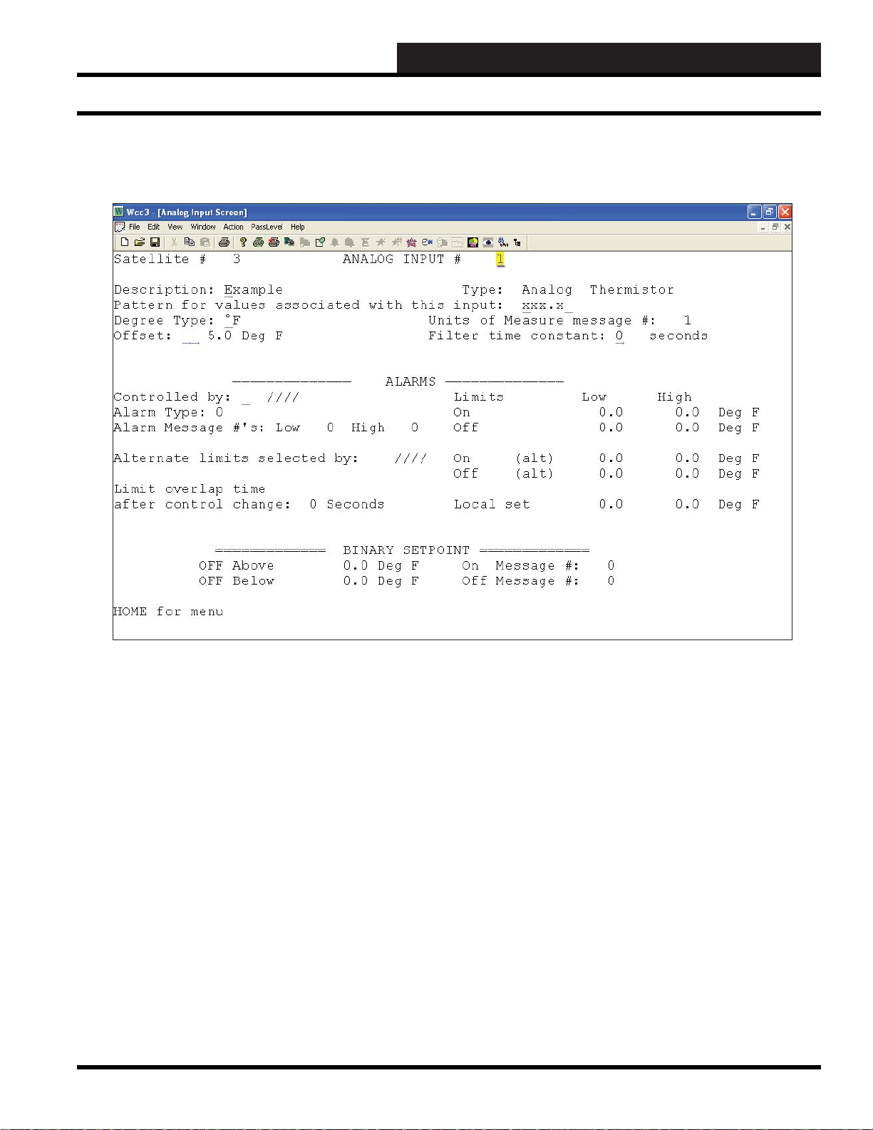
Analog Input Thermistor Screen
Analog Input Screen’s WCC III Logical Address is XXXAY, where XXX = Satellite Address, A = Analog Input, and Y = 1-8
ANALOG INPUT THERMIST OR SCREEN
Satellite # _______
Specifi es the number of the satellite which you are currently
editing. If you would like to edit a different satellite, use the arrow
keys to move the cursor to this fi eld, type in the desired satellite
number, and press
Analog Input # ________
This “fi eld” actually contains two separate fi elds. The fi rst fi eld
specifi es the point “type” (i.e., analog input, control output, analog
output, etc.) and displays the current type in textual form. Because
this is a “choice” fi eld, the list of available choices will be displayed
at the bottom of the screen:
<ANALOG INPUT, CONTROL OUTPUT, ANALOG OUTPUT,
TREND LOGGING, LOGIC SWITCH, BINARY OUTPUT>
You may make your selection by pressing the <space bar> until
the desired choice appears and then pressing <Enter>. (If you select
a point type that is different than that currently being displayed, the
screen will be rewritten with the appropriate screen and data.)
<Enter>.
Additionally, this fi eld specifi es the point number to edit. For the
Analog Input Screen, this number can range from one to eight,
corresponding from A1 to A8, respectively. If you would like to
edit a different point, move the cursor to this fi eld by using the
arrow keys, enter the desired point number, and press
Description:
A short message is entered here which is displayed on Summary
Screens to help you remember points within the system. You
may enter up to ten characters (control codes, ALT codes, and the
double quote character are not allowed).
Type: Analog Thermistor
This fi eld is automatically fi lled in by the system. On screens 2-8,
this will always read “ANALOG.” On screen number 1, it will
read either “ANALOG” or “PULSE” depending on the position
of the pulse switch on the satellite controller.
<Enter>.
WCC III Technical Guide
3-21
Page 26

WCC3.EXE SCREEN DESCRIPTIONS
Analog Input Thermistor Screen
Sensor Type
This is a choice fi eld for Analog types only. A list of available
choices will be displayed at the bottom of the screen:
<General, Thermistor, Resistor,
Resistor+, RawCount, Thermistor+>
You may make your selection by pressing the <space bar> until
the desired Analog Type has been selected and then pressing
<Enter>.
Thermistor = Used to setup WattMaster 10K type 3 curve
thermistors.
NOTE: The associated analog input jumper on the satellite
controller must also be set to “THERM” in order for this
screen to display the proper temperature value.
Pattern for Values Associated With This Input:
Specifi es where you would like the decimal point to appear in the
value displayed by the system. Because this is a “choice” fi eld,
a list of available choices will be displayed at the bottom of the
screen:
< x,xxx , xxx.x , xx.xx , x.xxx >
You may make your selection by pressing the <space bar>
until the desired data pattern has been selected and then pressing
<Enter>.
Degree Type:
Specifi es how you would like the temperature displayed, in
Fahrenheit or Celsius. Because this is a “choice” fi eld, a list of
available choices will be displayed at the bottom of the screen:
< ºF, ºC >
You may make your selection by pressing the <space bar> until
the desired temperature choice has been selected and then pressing
<Enter>.
Offset:
There is an option to change the calibration of a thermistor sensor
(Usually due to the position or location of the thermistor sensor)
a few degrees plus or minus from the actual temperature that the
thermistor sensor is actually reading. Acceptable values in this
fi eld are numerical with both positive and negative (+/-) values.
Units of Measure Message #: 1
A number is entered here that references a message on the On/Off
Units Messages Screen. For example, if units-of-measure message
#1 is “Deg F,” entering “1” will cause “Deg F” to be displayed as
the units-of-measure for the analog input.
Filter Time Constant: ____ Seconds
Specifi es the sampling rate of the analog input. This is used by the
satellites to “fi lter” (or smooth) the analog input signal. This can be
used on inputs that “jump around” to reduce sporadic load control.
Because this is a “choice” fi eld, the list of available choices will be
displayed at the bottom of the screen:
< 0, 1, 2, 4, 8, 16, 32, 64 >
You may make your selection by pressing the <space bar> until
the desired fi lter time constant has been selected and then pressing
<Enter>.
------ALARMS------
Controlled by:
Specifi es the binary value that selects the ON or OFF alarm limits.
When this value is OFF , the OFF alarm limits are selected; when it
is ON, the ON alarm limits are selected.
Alarm Type:
Specifi es the priority (or “importance”) level for any alarms
generated by this input. Alarm types range from one (highest
priority) to eight (lowest priority). The system displays and e-mails
higher priority alarms fi rst. (The fi rst fi ve alarm priorities (1-5)
have e-mail-out-on-alarm capabilities.)
Alarm Message # Low: ___ High: ___
Specifi es a pair of message numbers, one for LOW alarms and
the second for any HIGH alarms. These numbers are used by
the system to reference a message which is entered on the Alarm
Message Screen.
3-22
Alternate Limits Selected By:
Specifi es the point that initiates the Alternate mode. When this
address is zero (or OFF), the Normal alarm limits are selected;
when it is one (or ON), the Alternate alarm limits are selected.
WCC III Technical Guide
Page 27

WCC3.EXE SCREEN DESCRIPTIONS
Analog Input Thermistor Screen
Limits Low High
On _____ _____ °. F
Off _____ _____ °. F
On (alt) _____ _____ °. F
Off (alt) _____ _____ °. F
Local Set _____ _____ °. F
This group of inputs specifi es the alarm limits for the “Normal,”
“Alternate,” and “Local Set” modes. Each mode has a LOW and
HIGH limit. When the value of the analog input goes out of these
limits, an alarm is generated, and the alarm will automatically
display and e-mail out.
There are two fi elds on this screen that determine which set of
limits are active—the status of the “Controlled by” fi eld and the
status of the “Alternate Limits selected by” fi eld. When the value
that has been input in the “Controlled by” fi eld is ON, either the
“On” limits or the “On (Alt)” limits are active depending on the
status of the value input in the “Alternate Limits selected by” fi eld.
If the value in the “Alternate” fi eld is On, the “On (Alt)” limits are
used, and when the “Alternate” value is OFF, the “On” limits are
used.
Alternate Limits Active Alarm
Controlled by: Selected by: Limits:
On Off On
On On On (Alt)
Off Off Off
Off On Off (Alt)
The local set alarm limits become active if the MCD quits
communicating with the satellite controller. After communications
are re-established, any alarms that occurred while the satellite was
in local set will be reported.
Limit overlap time after control change:
This specifi es the amount of time the WCC software will wait after
a control change (i.e., on/off schedule, alternate mode, local set
mode) before deciding to generate an alarm. The fi rst input is a
user-entered number from 1 to 60, and the second input is either
seconds or minutes. This second input is a “choice” fi eld; the list
of available choices will be displayed at the bottom of the screen:
<Seconds, Minutes>
------ BINARY SETPOINTS ------
____Above:____
____Below:____
These inputs are used to convert the analog signal to a binary (On/
Off) signal. The value that is going ON and OFF is a software point
referred to as a comparator. Each analog input has a comparator
associated with it named “Cn.” The comparator for analog input
#1 is “C1,” analog input number 2 is “C2,” and so on. The status of
the comparator can be seen on the Analog Input Summary Screen.
When the
user has
selected:
OFF Above &
OFF Below:
OFF Above &
ON Below:
ON Above &
OFF Below:
ON Above &
ON Below:
Because this is a “choice” fi eld, a list of available choices will be
displayed at the bottom of the screen:
You may make your selection by pressing the <space bar> until
the desired choice is selected and then pressing
On Message #:
Off Message #:
Specifi es a pair of message numbers, the fi rst for the ON state and
the second for the OFF state of the comparator. These numbers
are used by the system to reference a message on the ON/OFF
Units Message Screen. For example, the comparator might be set
up to come on when the outside air temperature is below 55 °F for
economizer operation. Set up the On/Off Message Screen so that
message #3 is “ECON” and message #4 is “REFRIG.” The “On
Message” number would be “3” (ECON), and the “OFF Message”
number would be “4” (REFRIG).
The value of the comparator is:
OFF when the Analog Input value is greater than the
ABOVE setpoint or less than the BELOW setpoint,
and ON when the Analog Input value is equal to
either one or between the two setpoints.
OFF when the Analog Input value is greater than
or equal to the ABOVE setpoint or until the Analog
Input value becomes less than the BELOW setpoint,
and ON when the Analog Input value is less than or
equal to BELOW setpoint or until the Analog Input
value becomes greater than the ABOVE setpoint.
OFF when the Analog Input value is less than or
equal to the BELOW setpoint or until the Analog
Input value becomes greater than the ABOVE
setpoint, and ON when the Analog Input value is
greater than or equal to the ABOVE setpoint or
until the Analog Input value becomes less than the
BELOW setpoint.
OFF when the Analog input value is equal to either
one or between the two setpoints, and ON when
the Analog Input value is greater than the ABOVE
setpoint or less than the BELOW setpoint.
<ON, OFF>
<Enter>.
WCC III Technical Guide
3-23
Page 28
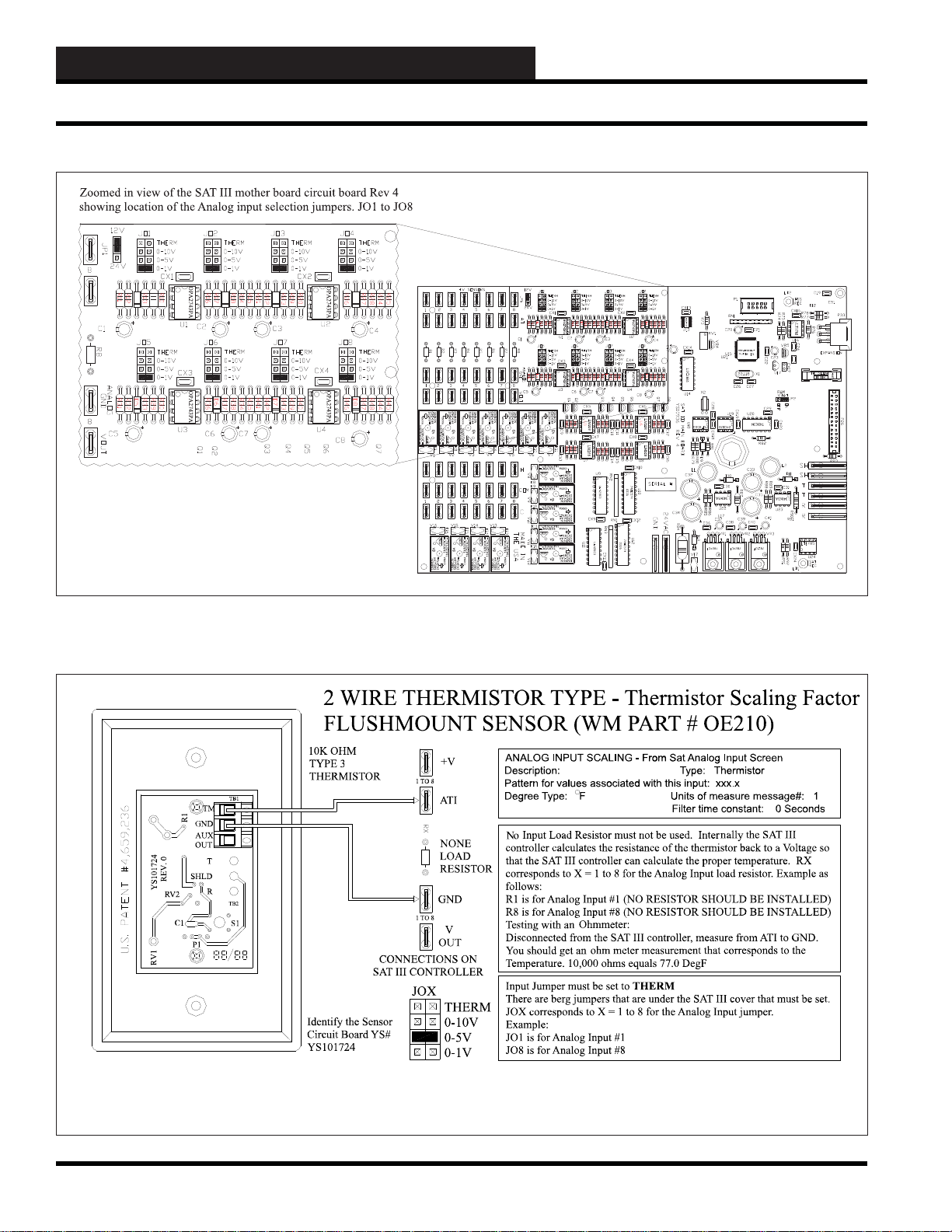
WCC3.EXE SCREEN DESCRIPTIONS
Analog Input Screen
3-24
WCC III Technical Guide
Page 29
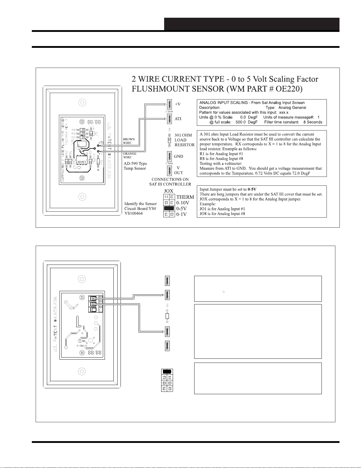
WCC3.EXE SCREEN DESCRIPTIONS
Analog Input Screen
REV. 0
YS101724
RV2
RV1
2 WIRE THERMISTOR TYPE - Thermistor Scaling Factor
FLUSHMOUNT SENSOR (WM PART # OE210)
10K OHM
TYPE 3
THERMISTOR
TB1
TM
R1
GND
AUX
OUT
T
SHLD
R
TB2
C1
S1
P1
CONNECTIONS ON
SAT III CONTROLLER
1TO 8
1TO 8
+V
AT I
NONE
LOAD
RESISTOR
GND
V
OUT
JOX
THERM
Identify the Sensor
Circuit Board YS#
YS101724
0-10V
0-5V
0-1V
ANALOG INPUT SCALING - From Sat Analog Input Screen
Description: Type: Thermistor
Pattern for values associated with this input: xxx.x
Degree Type: F Units of measure message#: 1
An Input Load Resistor must not be used. Internally, the SAT III
controller calculates the resistance of the thermistor back to a Voltage so
that the SAT III controller can calculate the proper temperature. RX
corresponds to X = 1 to 8 for the Analog Input load resistor. Example as
follows:
R1 is for Analog Input #1 (NO RESISTOR SHOULD BE INSTALLED)
R8 is for Analog Input #8 (NO RESISTOR SHOULD BE INSTALLED)
Testing with an Ohmmeter:
Disconnected from the SAT III controller, measure from TMP to GND
on the sensor. You should get an ohm meter measurement that
corresponds to the Temperature. 10,000 ohms equals 77.0 DegF
Input Jumper must be set to THERM
There are berg jumpers that are under the SAT III cover that must be set.
JOX corresponds to X = 1 to 8 for the Analog Input jumper.
Example:
JO1 is for Analog Input #1
JO8 is for Analog Input #8
Filter time constant: 0 Seconds
WCC III Technical Guide
3-25
Page 30
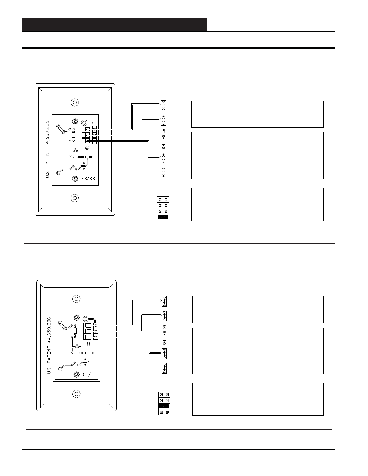
WCC3.EXE SCREEN DESCRIPTIONS
Analog Input Screen
3 WIRE VOLTAGE TYPE - 0 to 1 Volt Scaling Factor
FLUSHMOUNT SENSOR (WM PART # OE222)
YS101545
RV1
+V
TB1
C1
R3
R2
TMP
ATI
GND
AUX
OUT
TB1
U1
R1
C2
REV. 2
RV2
S1
ORANGE
WIRE
BROWN
WIRE
VIOLET
WIRE
LM-34 Type
Temp Sensor
1 TO 8
AT I
NONE
LOAD
RESISTOR
GND
1 TO 8
V
OUT
ANALOG INPUT SCALING - From Sat Analog Input Screen
Description: Type: Analog General
Pattern for values associated with this input: xxx.x
Units @ 0 % Scale 0.0 DegF Units of measure message #: 1
@ full scale: 100.0 DegF Filter time constant: 8 Seconds
An Input Load Resistor must not be used to convert the Voltage so that the
SAT III controller can calculate the proper temperature. RX
corresponds to X = 1 to 8 for the Analog Input load resistor. Example as
follows:
R1 is for Analog Input #1 (NO RESISTOR SHOULD BE INSTALLED)
R8 is for Analog Input #8 (NO RESISTOR SHOULD BE INSTALLED)
Testing with a voltmeter:
Measure from ATI to GND. You should get a voltage measurement that
corresponds to the Temperature. 0.72 Volts DC equals 72.0 Deg F
CONNECTIONS ON
SAT III CONTROLLER
Input Jumper must be set to 0-1V
There are berg jumpers that are under the SAT III cover that must be set.
JOX corresponds to X = 1 to 8 for the Analog Input jumper.
Example:
JO1 is for Analog Input #1
JO8 is for Analog Input #8
Identify the Sensor
Circuit Board YS#
YS101545
JOX
THERM
0-10V
0-5V
0-1V
3 WIRE VOLTAGE TYPE - 0 to 5 Volt Scaling Factor
FLUSHMOUNT SENSOR (WM PART # OE222)
3-26
+V
TB1
C1
R3
R2
TMP
ATI
GND
AUX
OUT
RV1
REV. 2
YS101545
RV2
TB1
U1
R1
C2
S1
ORANGE
WIRE
BROWN
WIRE
VIOLET
WIRE
LM-34 Type
Temp Sensor
1TO 8
AT I
NONE
LOAD
RESISTOR
GND
1TO 8
V
OUT
ANALOG INPUT SCALING - From Sat Analog Input Screen
Description: Type: Analog General
Pattern for values associated with this input: xxx.x
Units @ 0 % Scale 0.0 Deg F Units of measure message #: 1
@ full scale: 500.0 Deg F Filter time constant: 8 Seconds
An Input Load Resistor must not be used to convert the Voltage so that the
SAT III controller can calculate the proper temperature. RX
corresponds to X = 1 to 8 for the Analog Input load resistor. Example as
follows:
R1 is for Analog Input #1 (NO RESISTOR SHOULD BE INSTALLED)
R8 is for Analog Input #8 (NO RESISTOR SHOULD BE INSTALLED)
Testing with a voltmeter:
Measure from ATI to GND. You should get a voltage measurement that
corresponds to the Temperature. 0.72 Volts DC equals 72.0 Deg F
CONNECTIONS ON
SAT III CONTROLLER
Identify the Sensor
Circuit Board YS#
YS101545
JOX
THERM
0-10V
0-5V
0-1V
Input Jumper must be set to 0-5V
There are berg jumpers that are under the SAT III cover that must be set.
JOX corresponds to X = 1 to 8 for the Analog Input jumper.
Example:
JO1 is for Analog Input #1
JO8 is for Analog Input #8
WCC III Technical Guide
Page 31
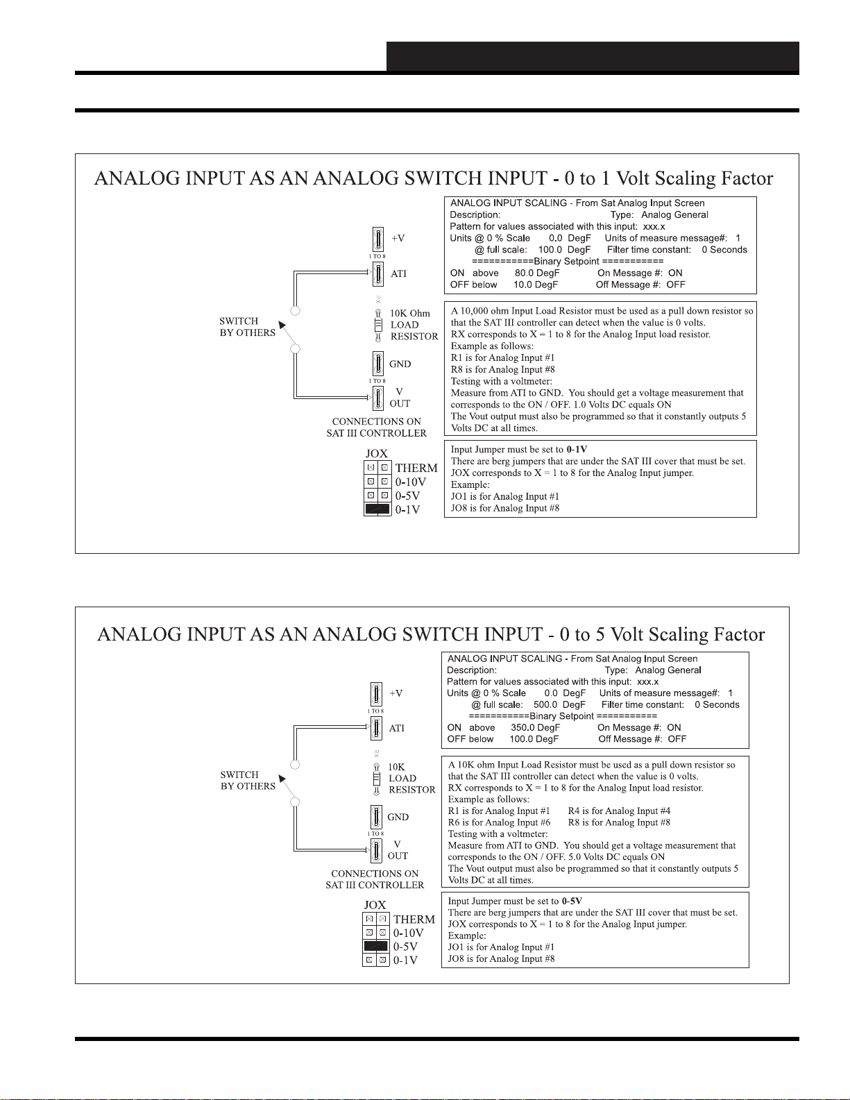
WCC3.EXE SCREEN DESCRIPTIONS
Analog Input Screen
WCC III Technical Guide
3-27
Page 32

WCC3.EXE SCREEN DESCRIPTIONS
Analog Input Screen
3-28
WCC III Technical Guide
Page 33

WCC3.EXE SCREEN DESCRIPTIONS
Analog Input Screen
WCC III Technical Guide
3-29
Page 34

WCC3.EXE SCREEN DESCRIPTIONS
Analog Input Screen
3-30
not
WCC III Technical Guide
Page 35

WCC3.EXE SCREEN DESCRIPTIONS
Analog Input Screen
WCC III Technical Guide
3-31
Page 36
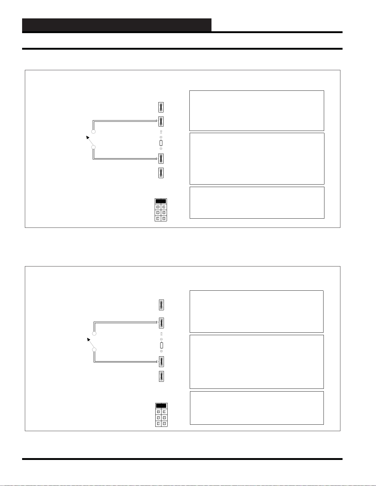
WCC3.EXE SCREEN DESCRIPTIONS
Analog Input Screen
ANALOG INPUT AS AN ANALOG SWITCH INPUT - Thermistor Scaling Factor
0-1V INPUT
SWITCH
BY OTHERS
+V
1TO 8
AT I
NO
LOAD
RESISTOR
GND
1TO 8
V
OUT
CONNECTIONS ON
SAT III CONTROLLER
JOX
THERM
0-10V
0-5V
0-1V
ANALOG INPUT SCALING - From Sat Analog Input Screen
Description: Type: Analog General
Pattern for values associated with this input: xxx.x
Units @ 0 % Scale 0.0 Deg F Units of measure message #: 1
@ full scale: 100.0 Deg F Filter time constant: 0 Seconds
===========Binary Setpoint ===========
OFF above 80.0 Deg F On Message #: ON
ON below 50.0 Deg F Off Message #: OFF
An Input Load Resistor must not be used as a pull down resistor, because
the required 5 volts comes from the Thermistor pull up resistor.
RX corresponds to X = 1 to 8 for the Analog Input load resistor.
Example as follows:
R1 is for Analog Input #1 R4 is for Analog Input #4
R6 is for Analog Input #6 R8 is for Analog Input #8
Testing with a voltmeter:
Measure from ATI to GND. You should get a voltage measurement that
corresponds to the ON / OFF. 5.0 Volts DC equals OFF
The V-Out output is not used for this application.
Input Jumper must be set to THERM
There are berg jumpers that are under the SAT III cover that must be set.
JOX corresponds to X = 1 to 8 for the Analog Input jumper.
Example:
JO1 is for Analog Input #1
JO8 is for Analog Input #8
ANALOG INPUT AS AN ANALOG SWITCH INPUT - Thermistor Scaling Factor
0-5V INPUT
SWITCH
BY OTHERS
+V
1 TO 8
AT I
NO
LOAD
RESISTOR
GND
1 TO 8
V
OUT
CONNECTIONS ON
SAT III CONTROLLER
JOX
THERM
0-10V
0-5V
0-1V
ANALOG INPUT SCALING - From Sat Analog Input Screen
Description: Type: Analog General
Pattern for values associated with this input: xxx.x
Units @ 0 % Scale 0.0 Deg F Units of measure message #: 1
@ full scale: 500.0 Deg F Filter time constant: 0 Seconds
===========Binary Setpoint ===========
OFF above 400.0 Deg F On Message #: ON
ON below 100.0 Deg F Off Message #: OFF
An Input Load Resistor must not be used as a pull down resistor, because
the required 5 volts comes from the Thermistor pull up resistor.
RX corresponds to X = 1 to 8 for the Analog Input load resistor.
Example as follows:
R1 is for Analog Input #1 R4 is for Analog Input #4
R6 is for Analog Input #6 R8 is for Analog Input #8
Testing with a voltmeter:
Measure from ATI to GND. You should get a voltage measurement that
corresponds to the ON / OFF. 5.0 Volts DC equals OFF
The V-Out output is not used for this application.
Input Jumper must be set to THERM
There are berg jumpers that are under the SAT III cover that must be set.
JOX corresponds to X = 1 to 8 for the Analog Input jumper.
Example:
JO1 is for Analog Input #1
JO8 is for Analog Input #8
3-32
WCC III Technical Guide
Page 37
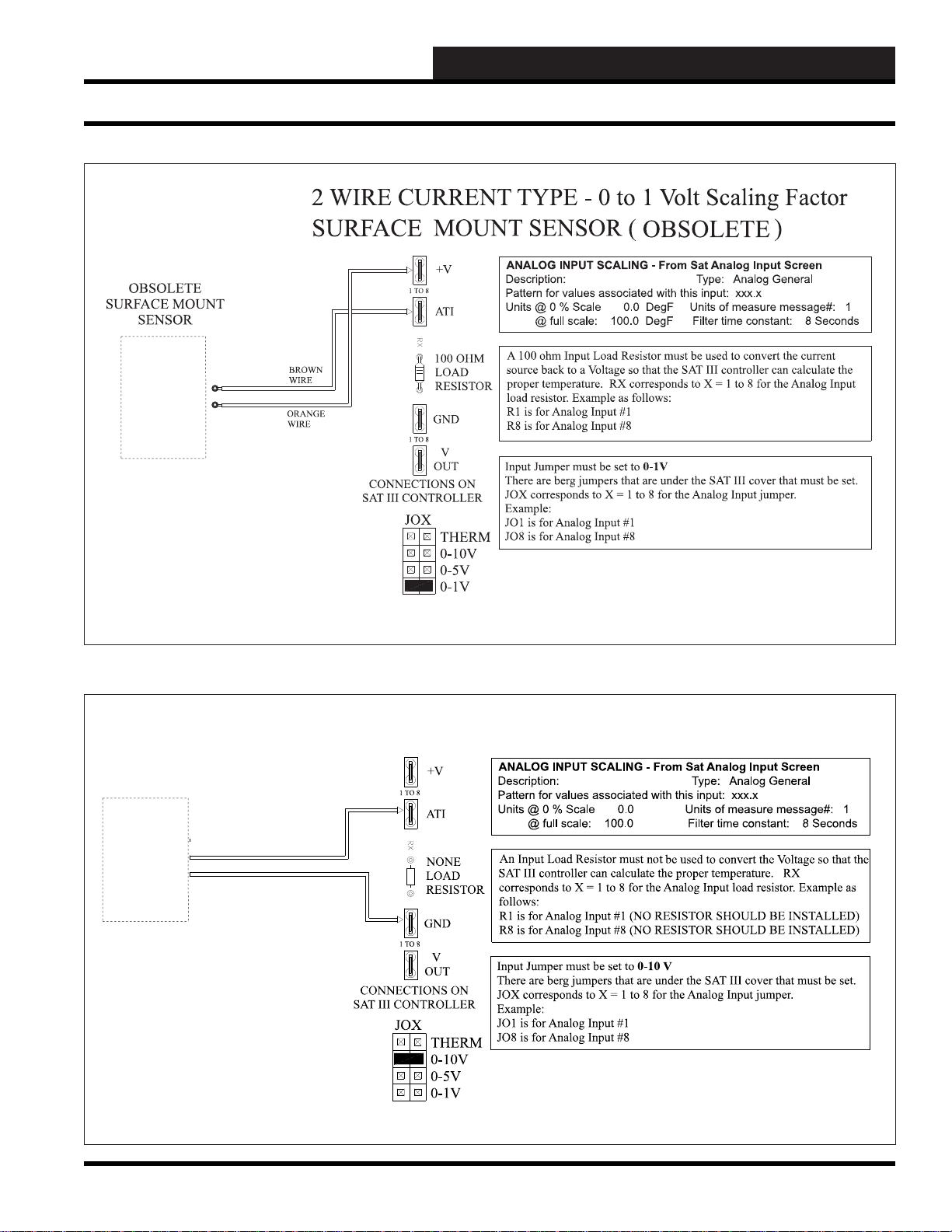
WCC3.EXE SCREEN DESCRIPTIONS
Analog Input Screen
FOR 0-10 VOLT INPUTS
WCC III Technical Guide
3-33
Page 38
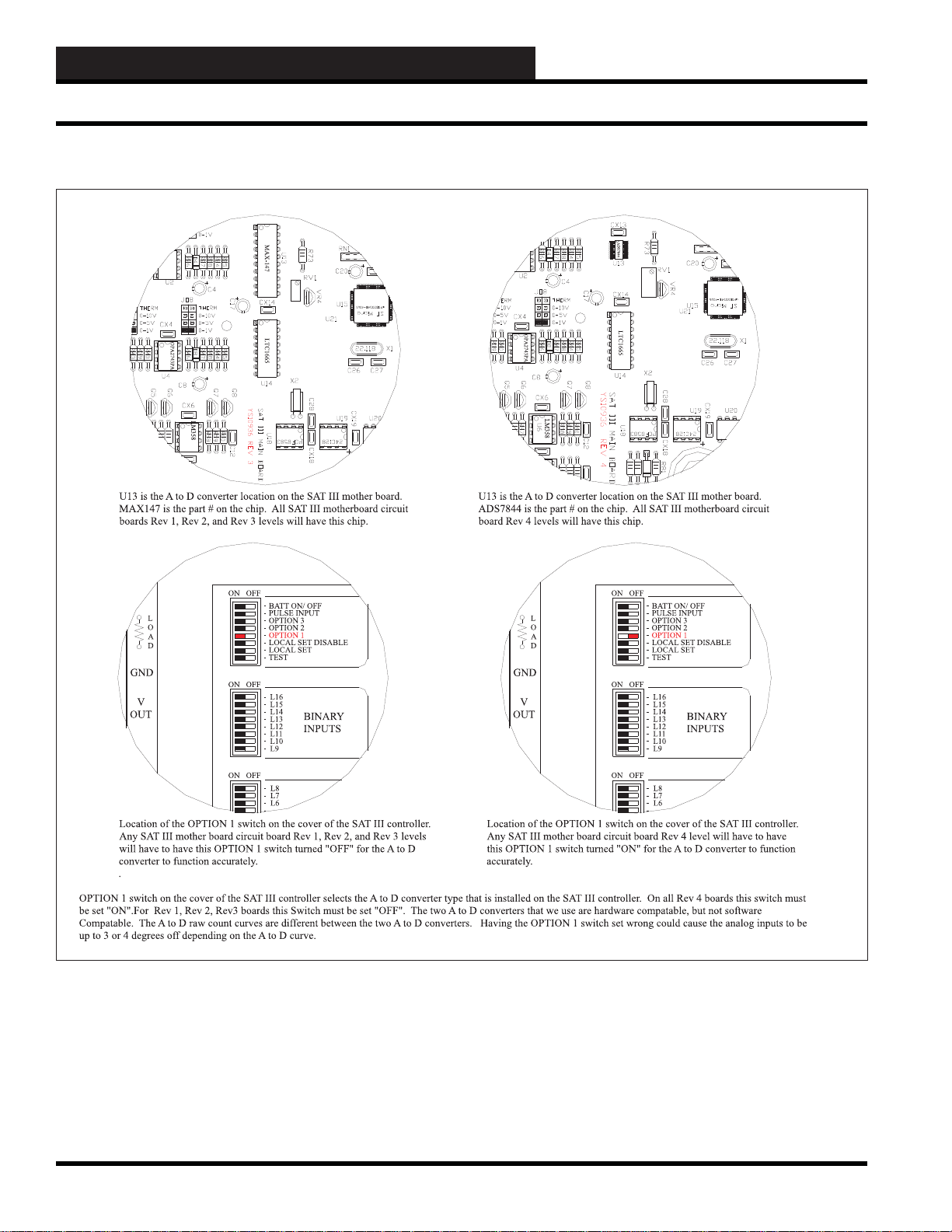
WCC3.EXE SCREEN DESCRIPTIONS
Analog Input Screen
3-34
WCC III Technical Guide
Page 39
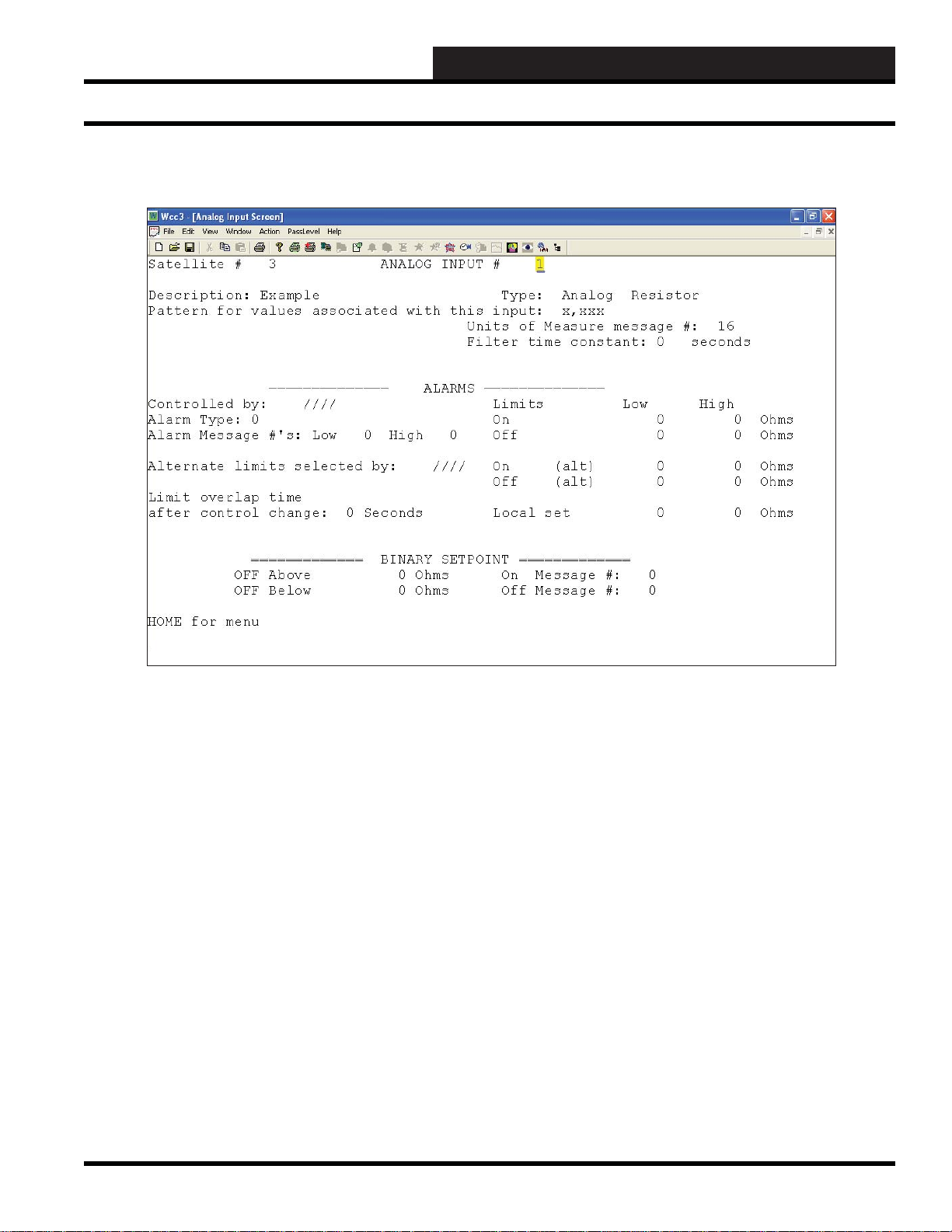
WCC3.EXE SCREEN DESCRIPTIONS
Analog Input Resistor Screen
Analog Input Screen’s WCC III Logical Address is XXXAY, where XXX = Satellite Address, A = Analog Input, and Y = 1-8
ANALOG INPUT RESIST OR SCREEN
Satellite # _______
Specifi es the number of the satellite which you are currently
editing. If you would like to edit a different satellite, use the arrow
keys to move the cursor to this fi eld, type in the desired satellite
number, and press
Analog Input # ________
This “fi eld” actually contains two separate fi elds. The fi rst fi eld
specifi es the point “type” (i.e., analog input, control output, analog
output, etc.) and displays the current type in textual form. Because
this is a “choice” fi eld, the list of available choices will be displayed
at the bottom of the screen:
<ANALOG INPUT, CONTROL OUTPUT, ANALOG OUTPUT,
TREND LOGGING, LOGIC SWITCH, BINARY OUTPUT>
You may make your selection by pressing the <space bar> until
the desired choice appears and then pressing <Enter>. (If you select
a point type that is different than that currently being displayed, the
screen will be rewritten with the appropriate screen and data.)
<Enter>.
Additionally, this fi eld specifi es the point number to edit. For the
Analog Input Screen, this number can range from one to eight,
corresponding from A1 to A8, respectively. If you would like to
edit a different point, move the cursor to this fi eld by using the
arrow keys, enter the desired point number, and press
Description:
A short message is entered here which is displayed on Summary
Screens to help you remember points within the system. You
may enter up to ten characters (control codes, ALT codes, and the
double quote character are not allowed).
Type: Analog Resistor
This fi eld is automatically fi lled in by the system. On screens 2-8,
this will always read “ANALOG.” On screen number 1, it will
read either “ANALOG” or “PULSE” depending on the position of
the pulse switch on the satellite controller.
<Enter>.
WCC III Technical Guide
3-35
Page 40

WCC3.EXE SCREEN DESCRIPTIONS
Analog Input Resistor Screen
Sensor Type
This is a choice fi eld for Analog types only. A list of available
choices will be displayed at the bottom of the screen:
<General, Thermistor, Resistor,
Resistor+, RawCount, Thermistor+>
You may make your selection by pressing the <space bar> until
the desired Analog Type has been selected and then pressing
<Enter>.
Resistor is used to measure resistace of a variable potentiometer.
A vailable inputs are 0 to 9999 ohms,
NOTE: The associated analog input jumper on the satellite
controller must also be set to “THERM” in order for this
screen to display the proper temperature value.
Pattern for Values Associated With This Input:
Specifi es where you would like the decimal point to appear in the
value displayed by the system. Because this is a “choice” fi eld,
a list of available choices will be displayed at the bottom of the
screen:
------ALARMS------
Controlled by:
Specifi es the binary value that selects the ON or OFF alarm limits.
When this value is OFF , the OFF alarm limits are selected; when it
is ON, the ON alarm limits are selected.
Alarm Type:
Specifi es the priority (or “importance”) level for any alarms
generated by this input. Alarm types range from one (highest
priority) to eight (lowest priority). The system displays and e-mails
higher priority alarms fi rst. (The fi rst fi ve alarm priorities (1-5)
have e-mail-out-on-alarm capabilities.)
Alarm Message # Low: ___ High: ___
Specifi es a pair of message numbers, one for LOW alarms and
the second for any HIGH alarms. These numbers are used by
the system to reference a message which is entered on the Alarm
Message Screen.
Alternate Limits Selected By:
Specifi es the point that initiates the Alternate mode. When this
address is zero (or OFF), the Normal alarm limits are selected;
when it is one (or ON), the Alternate alarm limits are selected.
< x,xxx , xxx.x , xx.xx , x.xxx >
You may make your selection by pressing the <space bar>
until the desired data pattern has been selected and then pressing
<Enter>.
Units of Measure Message #: 16
A number is entered here that references a message on the On/Off
Units Messages Screen. For example, if units-of-measure message
#16 is “Ohms,” entering “16” will cause “Ohms” to be displayed
as the units-of-measure for the analog input.
Filter Time Constant: ____ Seconds
Specifi es the sampling rate of the analog input. This is used by the
satellites to “fi lter” (or smooth) the analog input signal. This can be
used on inputs that “jump around” to reduce sporadic load control.
Because this is a “choice” fi eld, the list of available choices will be
displayed at the bottom of the screen:
< 0, 1, 2, 4, 8, 16, 32, 64 >
You may make your selection by pressing the <space bar> until
the desired fi lter time constant has been selected and then pressing
<Enter>.
Limits Low High
On _____ _____ °. F
Off _____ _____ °. F
On (alt) _____ _____ °. F
Off (alt) _____ _____ °. F
Local Set _____ _____ °. F
This group of inputs specifi es the alarm limits for the “Normal,”
“Alternate,” and “Local Set” modes. Each mode has a LOW and
HIGH limit. When the value of the analog input goes out of these
limits, an alarm is generated, and the alarm will automatically
display and e-mail out.
3-36
WCC III Technical Guide
Page 41

WCC3.EXE SCREEN DESCRIPTIONS
Analog Input Resistor Screen
There are two fi elds on this screen that determine which set of
limits are active—the status of the “Controlled by” fi eld and the
status of the “Alternate Limits selected by” fi eld. When the value
that has been input in the “Controlled by” fi eld is ON, either the
“On” limits or the “On (Alt)” limits are active depending on the
status of the value input in the “Alternate Limits selected by” fi eld.
If the value in the “Alternate” fi eld is On, the “On (Alt)” limits are
used, and when the “Alternate” value is OFF, the “On” limits are
used.
Alternate Limits Active Alarm
Controlled by: Selected by: Limits:
On Off On
On On On (Alt)
Off Off Off
Off On Off (Alt)
The local set alarm limits become active if the MCD quits
communicating with the satellite controller. After communications
are re-established, any alarms that occurred while the satellite was
in local set will be reported.
Limit overlap time after control change:
This specifi es the amount of time the WCC software will wait after
a control change (i.e., on/off schedule, alternate mode, local set
mode) before deciding to generate an alarm. The fi rst input is a
user-entered number from 1 to 60, and the second input is either
seconds or minutes. This second input is a “choice” fi eld; the list
of available choices will be displayed at the bottom of the screen:
<Seconds, Minutes>
------ BINARY SETPOINTS ------
____Above:____
____Below:____
These inputs are used to convert the analog signal to a binary (On/
Off) signal. The value that is going ON and OFF is a software point
referred to as a comparator. Each analog input has a comparator
associated with it named “Cn.” The comparator for analog input
#1 is “C1,” analog input number 2 is “C2,” and so on. The status of
the comparator can be seen on the Analog Input Summary Screen.
When the
user has
selected:
OFF Above &
OFF Below:
OFF Above &
ON Below:
ON Above &
OFF Below:
ON Above &
ON Below:
The value of the comparator is:
OFF when the Analog Input value is greater than the
ABOVE setpoint or less than the BELOW setpoint,
and ON when the Analog Input value is equal to
either one or between the two setpoints.
OFF when the Analog Input value is greater than
or equal to the ABOVE setpoint or until the Analog
Input value becomes less than the BELOW setpoint,
and ON when the Analog Input value is less than or
equal to BELOW setpoint or until the Analog Input
value becomes greater than the ABOVE setpoint.
OFF when the Analog Input value is less than or
equal to the BELOW setpoint or until the Analog
Input value becomes greater than the ABOVE
setpoint, and ON when the Analog Input value is
greater than or equal to the ABOVE setpoint or
until the Analog Input value becomes less than the
BELOW setpoint.
OFF when the Analog input value is equal to either
one or between the two setpoints, and ON when
the Analog Input value is greater than the ABOVE
setpoint or less than the BELOW setpoint.
WCC III Technical Guide
Because this is a “choice” fi eld, a list of available choices will be
displayed at the bottom of the screen:
<ON, OFF>
You may make your selection by pressing the <space bar> until
the desired choice is selected and then pressing
On Message #:
Off Message #:
<Enter>.
Specifi es a pair of message numbers, the fi rst for the ON state and
the second for the OFF state of the comparator. These numbers
are used by the system to reference a message on the ON/OFF
Units Message Screen. For example, the comparator might be set
up to come on when the outside air temperature is below 55 °F for
economizer operation. Set up the On/Off Message Screen so that
message #3 is “ECON” and message #4 is “REFRIG.” The “On
Message” number would be “3” (ECON), and the “OFF Message”
number would be “4” (REFRIG).
3-37
Page 42

WCC3.EXE SCREEN DESCRIPTIONS
Analog Input Resistor+ Screen
Analog Input Screen’s WCC III Logical Address is XXXAY, where XXX = Satellite Address, A = Analog Input, and Y = 1-8
ANALOG INPUT RESIST OR+ SCREEN
Satellite # _______
Specifi es the number of the satellite which you are currently
editing. If you would like to edit a different satellite, use the arrow
keys to move the cursor to this fi eld, type in the desired satellite
number, and press
Analog Input # ________
This “fi eld” actually contains two separate fi elds. The fi rst fi eld
specifi es the point “type” (i.e., analog input, control output, analog
output, etc.) and displays the current type in textual form. Because
this is a “choice” fi eld, the list of available choices will be displayed
at the bottom of the screen:
<ANALOG INPUT, CONTROL OUTPUT, ANALOG OUTPUT,
TREND LOGGING, LOGIC SWITCH, BINARY OUTPUT>
You may make your selection by pressing the <space bar> until
the desired choice appears and then pressing <Enter>. (If you select
a point type that is different than that currently being displayed, the
screen will be rewritten with the appropriate screen and data.)
<Enter>.
Additionally, this fi eld specifi es the point number to edit. For the
Analog Input Screen, this number can range from one to eight,
corresponding from A1 to A8, respectively. If you would like to
edit a different point, move the cursor to this fi eld by using the
arrow keys, enter the desired point number, and press
Description:
A short message is entered here which is displayed on Summary
Screens to help you remember points within the system. You
may enter up to ten characters (control codes, ALT codes, and the
double quote character are not allowed).
Type: Analog Resistor+
This fi eld is automatically fi lled in by the system. On screens 2-8,
this will always read “ANALOG.” On screen number 1, it will
read either “ANALOG” or “PULSE” depending on the position of
the pulse switch on the satellite controller.
<Enter>.
3-38
WCC III Technical Guide
Page 43

WCC3.EXE SCREEN DESCRIPTIONS
Analog Input Resistor+ Screen
Sensor Type
This is a choice fi eld for Analog types only. A list of available
choices will be displayed at the bottom of the screen:
<General, Thermistor, Resistor,
Resistor+, RawCount, Thermistor+>
You may make your selection by pressing the <space bar> until
the desired Analog Type has been selected and then pressing
<Enter>.
Resistor+ is used to set up different types of thermistors.
WattMaster thermistors are 10K type 3 curve. You would enter
values on the screen to correspond to different values and type
curves of thermistors. Available inputs are 0 to 9999 ohms,
NOTE: The associated analog input jumper on the satellite
controller must also be set to “THERM” in order for this
screen to display the proper temperature value.
Pattern for Values Associated With This Input:
Specifi es where you would like the decimal point to appear in the
value displayed by the system. Because this is a “choice” fi eld,
a list of available choices will be displayed at the bottom of the
screen:
< x,xxx , xxx.x , xx.xx , x.xxx >
You may make your selection by pressing the <space bar>
until the desired data pattern has been selected and then pressing
<Enter>.
Resistor Bias:
This is the Bias resistor in the satellite. This is currently a 10 K
Ohm resistor and is soldered onto the satellite’s main circuit board.
This Bias resistor can be changed but will need to be specifi ed
when the satellite is ordered from WattMaster Controls.
Resistor to Ohms ratio: _______ / KOhm
This is the calibration for the scaling of the thermistor. There is
a value that is needed for correct thermistor Resistance to Ohms
calculations.
Units of Measure Message #: 16
A number is entered here that references a message on the On/Off
Units Messages Screen. For example, if units-of-measure message
#16 is “Ohms,” entering “16” will cause “Ohms” to be displayed
as the units-of-measure for the analog input.
Filter Time Constant: ____ Seconds
Specifi es the sampling rate of the analog input. This is used by the
satellites to “fi lter” (or smooth) the analog input signal. This can be
used on inputs that “jump around” to reduce sporadic load control.
Because this is a “choice” fi eld, the list of available choices will be
displayed at the bottom of the screen:
< 0, 1, 2, 4, 8, 16, 32, 64 >
You may make your selection by pressing the <space bar> until
the desired fi lter time constant has been selected and then pressing
<Enter>.
------ALARMS------
Controlled by:
Specifi es the binary value that selects the ON or OFF alarm limits.
When this value is OFF , the OFF alarm limits are selected; when it
is ON, the ON alarm limits are selected.
Alarm Type:
Specifi es the priority (or “importance”) level for any alarms
generated by this input. Alarm types range from one (highest
priority) to eight (lowest priority). The system displays and e-mails
higher priority alarms fi rst. (The fi rst fi ve alarm priorities (1-5)
have e-mail-out-on-alarm capabilities.)
Unit Offset:
There is an option to change the calibration of a thermistor sensor
(usually due to the position or location of the thermistor sensor) a
few Ohms plus or minus from the actual Ohms that the thermistor
sensor is actually reading. Acceptable values in this fi eld are
numerical with both positive and negative (+/-) values.
WCC III Technical Guide
Alarm Message # Low: ___ High: ___
Specifi es a pair of message numbers, one for LOW alarms and
the second for any HIGH alarms. These numbers are used by
the system to reference a message which is entered on the Alarm
Message Screen.
3-39
Page 44

WCC3.EXE SCREEN DESCRIPTIONS
Analog Input Resistor + Screen
Alternate Limits Selected By:
Specifi es the point that initiates the Alternate mode. When this
address is zero (or OFF), the Normal alarm limits are selected;
when it is one (or ON), the Alternate alarm limits are selected.
Limits Low High
On _____ _____ °. F
Off _____ _____ °. F
On (alt) _____ _____ °. F
Off (alt) _____ _____ °. F
Local Set _____ _____ °. F
This group of inputs specifi es the alarm limits for the “Normal,”
“Alternate,” and “Local Set” modes. Each mode has a LOW and
HIGH limit. When the value of the analog input goes out of these
limits, an alarm is generated, and the alarm will automatically
display and e-mail out.
There are two fi elds on this screen that determine which set of
limits are active—the status of the “Controlled by” fi eld and the
status of the “Alternate Limits selected by” fi eld. When the value
that has been input in the “Controlled by” fi eld is ON, either the
“On” limits or the “On (Alt)” limits are active depending on the
status of the value input in the “Alternate Limits selected by” fi eld.
If the value in the “Alternate” fi eld is On, the “On (Alt)” limits are
used, and when the “Alternate” value is OFF, the “On” limits are
used.
Alternate Limits Active Alarm
Controlled by: Selected by: Limits:
On Off On
On On On (Alt)
Off Off Off
Off On Off (Alt)
The local set alarm limits become active if the MCD quits
communicating with the satellite controller. After communications
are re-established, any alarms that occurred while the satellite was
in local set will be reported.
Limit overlap time after control change:
This specifi es the amount of time the WCC software will wait after
a control change (i.e., on/off schedule, alternate mode, local set
mode) before deciding to generate an alarm. The fi rst input is a
user-entered number from 1 to 60, and the second input is either
seconds or minutes. This second input is a “choice” fi eld; the list
of available choices will be displayed at the bottom of the screen:
<Seconds, Minutes>
------ BINARY SETPOINTS ------
____Above:____
____Below:____
These inputs are used to convert the analog signal to a binary (On/
Off) signal. The value that is going ON and OFF is a software point
referred to as a comparator. Each analog input has a comparator
associated with it named “Cn.” The comparator for analog input
#1 is “C1,” analog input number 2 is “C2,” and so on. The status of
the comparator can be seen on the Analog Input Summary Screen.
When the
user has
selected:
OFF Above &
OFF Below:
OFF Above &
ON Below:
ON Above &
OFF Below:
ON Above &
ON Below:
Because this is a “choice” fi eld, a list of available choices will be
displayed at the bottom of the screen:
You may make your selection by pressing the <space bar> until
the desired choice is selected and then pressing
On Message #:
Off Message #:
Specifi es a pair of message numbers, the fi rst for the ON state and
the second for the OFF state of the comparator. These numbers
are used by the system to reference a message on the ON/OFF
Units Message Screen. For example, the comparator might be set
up to come on when the outside air temperature is below 55 °F for
economizer operation. Set up the On/Off Message Screen so that
message #3 is “ECON” and message #4 is “REFRIG.” The “On
Message” number would be “3” (ECON), and the “OFF Message”
number would be “4” (REFRIG).
The value of the comparator is:
OFF when the Analog Input value is greater than the
ABOVE setpoint or less than the BELOW setpoint,
and ON when the Analog Input value is equal to
either one or between the two setpoints.
OFF when the Analog Input value is greater than
or equal to the ABOVE setpoint or until the Analog
Input value becomes less than the BELOW setpoint,
and ON when the Analog Input value is less than or
equal to BELOW setpoint or until the Analog Input
value becomes greater than the ABOVE setpoint.
OFF when the Analog Input value is less than or
equal to the BELOW setpoint or until the Analog
Input value becomes greater than the ABOVE
setpoint, and ON when the Analog Input value is
greater than or equal to the ABOVE setpoint or
until the Analog Input value becomes less than the
BELOW setpoint.
OFF when the Analog input value is equal to either
one or between the two setpoints, and ON when
the Analog Input value is greater than the ABOVE
setpoint or less than the BELOW setpoint.
<ON, OFF>
<Enter>.
3-40
WCC III Technical Guide
Page 45

WCC3.EXE SCREEN DESCRIPTIONS
Analog Input RawCount Screen
Analog Input Screen’s WCC III Logical Address is XXXAY, where XXX = Satellite Address, A = Analog Input, and Y = 1-8
ANALOG INPUT RAWCOUNT SCREEN
Satellite # _______
Specifi es the number of the satellite which you are currently
editing. If you would like to edit a different satellite, use the arrow
keys to move the cursor to this fi eld, type in the desired satellite
number, and press <Enter>.
Analog Input # ________
This “fi eld” actually contains two separate fi elds. The fi rst fi eld
specifi es the point “type” (i.e., analog input, control output, analog
output, etc.) and displays the current type in textual form. Because
this is a “choice” fi eld, the list of available choices will be displayed
at the bottom of the screen:
<ANALOG INPUT, CONTROL OUTPUT, ANALOG OUTPUT,
TREND LOGGING, LOGIC SWITCH, BINARY OUTPUT>
You may make your selection by pressing the <space bar> until
the desired choice appears and then pressing
a point type that is different than that currently being displayed, the
screen will be rewritten with the appropriate screen and data.)
<Enter>. (If you select
Additionally, this fi eld specifi es the point number to edit. For the
Analog Input Screen, this number can range from one to eight,
corresponding from A1 to A8, respectively. If you would like to
edit a different point, move the cursor to this fi eld by using the
arrow keys, enter the desired point number, and press
Description:
A short message is entered here which is displayed on Summary
Screens to help you remember points within the system. You
may enter up to ten characters (control codes, ALT codes, and the
double quote character are not allowed).
Type: RawCount
This fi eld is automatically fi lled in by the system. On screens 2-8,
this will always read “ANALOG.” On screen number 1, it will
read either “ANALOG” or “PULSE” depending on the position
of the pulse switch on the satellite controller.
<Enter>.
WCC III Technical Guide
3-41
Page 46

WCC3.EXE SCREEN DESCRIPTIONS
Analog Input RawCount Screen
Sensor Type
This is a choice fi eld for Analog types only. A list of available
choices will be displayed at the bottom of the screen:
<General, Thermistor, Resistor,
Resistor+, RawCount, Thermistor+>
You may make your selection by pressing the <space bar> until
the desired Analog Type has been selected and then pressing
<Enter>.
RawCount is the raw count value straight from the 12 bit A to D
converter. Used for testing and or calibrating to see if the analog
signal is linear, so that you may test the non-linear curve of any
sensor to determine if any offset is needed.
Units of Measure Message #: 1
A number is entered here that references a message on the On/Off
Units Messages Screen. For example, if units-of-measure message
#1 is “Data,” entering “1” will cause “Data” to be displayed as the
units-of-measure for the analog input.
Filter Time Constant: ____ Seconds
Specifi es the sampling rate of the analog input. This is used by the
satellites to “fi lter” (or smooth) the analog input signal. This can be
used on inputs that “jump around” to reduce sporadic load control.
Because this is a “choice” fi eld, the list of available choices will be
displayed at the bottom of the screen:
< 0, 1, 2, 4, 8, 16, 32, 64 >
You may make your selection by pressing the <space bar> until
the desired fi lter time constant has been selected and then pressing
<Enter>.
------ALARMS------
Controlled by:
Specifi es the binary value that selects the ON or OFF alarm limits.
When this value is OFF , the OFF alarm limits are selected; when it
is ON, the ON alarm limits are selected.
Alarm Type:
Specifi es the priority (or “importance”) level for any alarms
generated by this input. Alarm types range from one (highest
priority) to eight (lowest priority). The system displays and e-mails
higher priority alarms fi rst. (The fi rst fi ve alarm priorities (1-5)
have e-mail-out-on-alarm capabilities.)
Alarm Message # Low: ___ High: ___
Specifi es a pair of message numbers, one for LOW alarms and
the second for any HIGH alarms. These numbers are used by
the system to reference a message which is entered on the Alarm
Message Screen.
Alternate Limits Selected By:
Specifi es the point that initiates the Alternate mode. When this
address is zero (or OFF), the Normal alarm limits are selected;
when it is one (or ON), the Alternate alarm limits are selected.
Limits Low High
On _____ _____ °. F
Off _____ _____ °. F
On (alt) _____ _____ °. F
Off (alt) _____ _____ °. F
Local Set _____ _____ °. F
This group of inputs specifi es the alarm limits for the “Normal,”
“Alternate,” and “Local Set” modes. Each mode has a LOW and
HIGH limit. When the value of the analog input goes out of these
limits, an alarm is generated, and the alarm will automatically
display and e-mail out.
3-42
WCC III Technical Guide
Page 47

WCC3.EXE SCREEN DESCRIPTIONS
Analog Input RawCount Screen
There are two fi elds on this screen that determine which set of
limits are active—the status of the “Controlled by” fi eld and the
status of the “Alternate Limits selected by” fi eld. When the value
that has been input in the “Controlled by” fi eld is ON, either the
“On” limits or the “On (Alt)” limits are active depending on the
status of the value input in the “Alternate Limits selected by” fi eld.
If the value in the “Alternate” fi eld is On, the “On (Alt)” limits are
used, and when the “Alternate” value is OFF, the “On” limits are
used.
Alternate Limits Active Alarm
Controlled by: Selected by: Limits:
On Off On
On On On (Alt)
Off Off Off
Off On Off (Alt)
The local set alarm limits become active if the MCD quits
communicating with the satellite controller. After communications
are re-established, any alarms that occurred while the satellite was
in local set will be reported.
Limit overlap time after control change:
This specifi es the amount of time the WCC software will wait after
a control change (i.e., on/off schedule, alternate mode, local set
mode) before deciding to generate an alarm. The fi rst input is a
user-entered number from 1 to 60, and the second input is either
seconds or minutes. This second input is a “choice” fi eld; the list
of available choices will be displayed at the bottom of the screen:
<Seconds, Minutes>
------ BINARY SETPOINTS ------
____Above:____
____Below:____
These inputs are used to convert the analog signal to a binary (On/
Off) signal. The value that is going ON and OFF is a software point
referred to as a comparator. Each analog input has a comparator
associated with it named “Cn.” The comparator for analog input
#1 is “C1,” analog input number 2 is “C2,” and so on. The status of
the comparator can be seen on the Analog Input Summary Screen.
When the
user has
selected:
OFF Above &
OFF Below:
OFF Above &
ON Below:
ON Above &
OFF Below:
ON Above &
ON Below:
The value of the comparator is:
OFF when the Analog Input value is greater than the
ABOVE setpoint or less than the BELOW setpoint,
and ON when the Analog Input value is equal to
either one or between the two setpoints.
OFF when the Analog Input value is greater than
or equal to the ABOVE setpoint or until the Analog
Input value becomes less than the BELOW setpoint,
and ON when the Analog Input value is less than or
equal to BELOW setpoint or until the Analog Input
value becomes greater than the ABOVE setpoint.
OFF when the Analog Input value is less than or
equal to the BELOW setpoint or until the Analog
Input value becomes greater than the ABOVE
setpoint, and ON when the Analog Input value is
greater than or equal to the ABOVE setpoint or
until the Analog Input value becomes less than the
BELOW setpoint.
OFF when the Analog input value is equal to either
one or between the two setpoints, and ON when
the Analog Input value is greater than the ABOVE
setpoint or less than the BELOW setpoint.
WCC III Technical Guide
Because this is a “choice” fi eld, a list of available choices will be
displayed at the bottom of the screen:
<ON, OFF>
You may make your selection by pressing the <space bar> until
the desired choice is selected and then pressing
On Message #:
Off Message #:
<Enter>.
Specifi es a pair of message numbers, the fi rst for the ON state and
the second for the OFF state of the comparator. These numbers
are used by the system to reference a message on the ON/OFF
Units Message Screen. For example, the comparator might be set
up to come on when the outside air temperature is below 55 °F for
economizer operation. Set up the On/Off Message Screen so that
message #3 is “ECON” and message #4 is “REFRIG.” The “On
Message” number would be “3” (ECON), and the “OFF Message”
number would be “4” (REFRIG).
3-43
Page 48

WCC3.EXE SCREEN DESCRIPTIONS
Analog Input Thermistor+ Screen
Analog Input Screen’s WCC III Logical Address is XXXAY, where XXX = Satellite Address, A = Analog Input, and Y = 1-8
ANALOG INPUT THERMIST OR+ SCREEN
Satellite # 1 ANALOG INPUT # 2
Description: Room Type: Analog Thermistor+
Pattern for values associated with this input: xxx.x
Degree Type: ºF Units of Measure message #: 1
Offset: 0.0 Deg F Filter time constant: 0 seconds
b0: 0.0014062 b1: 0.00023671 b3: 0.0000001023
__________________ ALARMS _____________________
Controlled by: 0 Limits Low High
Alarm Type: 1 On 40.0 60.0 Deg F
Alarm Message #’s: Low 1 High 2 Off 40.0 60.0 Deg F
Alternate limits selected by: 0 On (alt) 40.0 60.0 Deg F
Off (alt) 40.0 60.0 Deg F
Limit overlap time
after control change: 0 Seconds Local set 40.0 60.0 Deg F
================= BINARY SETPOINT ===================
OFF Above 8.0 Deg F On Message #: 5 Flow
OFF Below 5.0 Deg F Off Message #: 6 No Flow
HOME for menu
Satellite # _______
Specifi es the number of the satellite which you are currently
editing. If you would like to edit a different satellite, use the arrow
keys to move the cursor to this fi eld, type in the desired satellite
number, and press <Enter>.
Analog Input # ________
This “fi eld” actually contains two separate fi elds. The fi rst fi eld
specifi es the point “type” (i.e., analog input, control output, analog
output, etc.) and displays the current type in textual form. Because
this is a “choice” fi eld, the list of available choices will be displayed
at the bottom of the screen:
<ANALOG INPUT, CONTROL OUTPUT, ANALOG OUTPUT,
TREND LOGGING, LOGIC SWITCH, BINARY OUTPUT>
You may make your selection by pressing the <space bar> until
the desired choice appears and then pressing <Enter>. (If you select
a point type that is different than that currently being displayed, the
screen will be rewritten with the appropriate screen and data.)
Additionally, this fi eld specifi es the point number to edit. For the
Analog Input Screen, this number can range from one to eight,
corresponding from A1 to A8, respectively. If you would like to
edit a different point, move the cursor to this fi eld by using the
arrow keys, enter the desired point number, and press
Description:
A short message is entered here which is displayed on Summary
Screens to help you remember points within the system. You
may enter up to ten characters (control codes, ALT codes, and the
double quote character are not allowed).
Type: Analog Thermistor+
This fi eld is automatically fi lled in by the system. On screens 2-8,
this will always read “ANALOG.” On screen number 1, it will
read either “ANALOG” or “PULSE” depending on the position
of the pulse switch on the satellite controller.
<Enter>.
3-44
WCC III Technical Guide
Page 49

WCC3.EXE SCREEN DESCRIPTIONS
Analog Input Thermistor+ Screen
Sensor Type
This is a choice fi eld for Analog types only. A list of available
choices will be displayed at the bottom of the screen:
<General, Thermistor, Resistor,
Resistor+, RawCount, Thermistor+>
You may make your selection by pressing the <space bar> until
the desired Analog Type has been selected and then pressing
<Enter>.
Thermistor+ is to be used if you are using a thermistor type sensor
that WattMaster Controls has not provided. Other thermistor type
sensors can be connected to the Satellite controller’s analog inputs
with this screen. Please consult the WattMaster Controls factory
for all other thermistor type sensors that you wish to connect to the
Satellite Controller. WattMaster Controls can provide the correct
b0, b1, b3 values at our option.
NOTE: The associated analog input jumper on the satellite
controller must also be set to “THERM” in order for this
screen to display the proper temperature value.
Pattern for Values Associated With This Input:
Specifi es where you would like the decimal point to appear in the
value displayed by the system. Because this is a “choice” fi eld,
a list of available choices will be displayed at the bottom of the
screen:
Offset:
There is an option to change the calibration of a thermistor sensor
(Usually due to the position or location of the thermistor sensor)
a few degrees plus or minus from the actual temperature that the
thermistor sensor is actually reading. Acceptable values in this
fi eld are numerical with both positive and negative (+/-) values.
Units of Measure Message #: 1
A number is entered here that references a message on the On/Off
Units Messages Screen. For example, if units-of-measure message
#1 is “Deg F,” entering “1” will cause “Deg F” to be displayed as
the units-of-measure for the analog input.
Filter Time Constant: ____ Seconds
Specifi es the sampling rate of the analog input. This is used by the
satellites to “fi lter” (or smooth) the analog input signal. This can be
used on inputs that “jump around” to reduce sporadic load control.
Because this is a “choice” fi eld, the list of available choices will be
displayed at the bottom of the screen:
< 0, 1, 2, 4, 8, 16, 32, 64 >
You may make your selection by pressing the <space bar> until
the desired fi lter time constant has been selected and then pressing
<Enter>.
------ALARMS------
< x,xxx , xxx.x , xx.xx , x.xxx >
You may make your selection by pressing the <space bar>
until the desired data pattern has been selected and then pressing
<Enter>.
Degree Type:
Specifi es how you would like the temperature displayed, in
Fahrenheit or Celsius. Because this is a “choice” fi eld, a list of
available choices will be displayed at the bottom of the screen:
< ºF, ºC >
You may make your selection by pressing the <space bar>
until the desired data pattern has been selected and then pressing
<Enter>.
WCC III Technical Guide
Controlled by:
Specifi es the binary value that selects the ON or OFF alarm limits.
When this value is OFF , the OFF alarm limits are selected; when it
is ON, the ON alarm limits are selected.
Alarm Type:
Specifi es the priority (or “importance”) level for any alarms
generated by this input. Alarm types range from one (highest
priority) to eight (lowest priority). The system displays and e-mails
higher priority alarms fi rst. (The fi rst fi ve alarm priorities (1-5)
have e-mail-out-on-alarm capabilities.)
Alarm Message # Low: ___ High: ___
Specifi es a pair of message numbers, one for LOW alarms and
the second for any HIGH alarms. These numbers are used by
the system to reference a message which is entered on the Alarm
Message Screen.
3-45
Page 50

WCC3.EXE SCREEN DESCRIPTIONS
Analog Input Thermistor+ Screen
Alternate Limits Selected By:
Specifi es the point that initiates the Alternate mode. When this
address is zero (or OFF), the Normal alarm limits are selected;
when it is one (or ON), the Alternate alarm limits are selected.
Limits Low High
On _____ _____ °. F
Off _____ _____ °. F
On (alt) _____ _____ °. F
Off (alt) _____ _____ °. F
Local Set _____ _____ °. F
This group of inputs specifi es the alarm limits for the “Normal,”
“Alternate,” and “Local Set” modes. Each mode has a LOW and
HIGH limit. When the value of the analog input goes out of these
limits, an alarm is generated, and the alarm will automatically
display and e-mail out.
There are two fi elds on this screen that determine which set of
limits are active—the status of the “Controlled by” fi eld and the
status of the “Alternate Limits selected by” fi eld. When the value
that has been input in the “Controlled by” fi eld is ON, either the
“On” limits or the “On (Alt)” limits are active depending on the
status of the value input in the “Alternate Limits selected by” fi eld.
If the value in the “Alternate” fi eld is On, the “On (Alt)” limits are
used, and when the “Alternate” value is OFF, the “On” limits are
used.
Alternate Limits Active Alarm
Controlled by: Selected by: Limits:
On Off On
On On On (Alt)
Off Off Off
Off On Off (Alt)
The local set alarm limits become active if the MCD quits
communicating with the satellite controller. After communications
are re-established, any alarms that occurred while the satellite was
in local set will be reported.
Limit overlap time after control change:
This specifi es the amount of time the WCC software will wait after
a control change (i.e., on/off schedule, alternate mode, local set
mode) before deciding to generate an alarm. The fi rst input is a
user-entered number from 1 to 60, and the second input is either
seconds or minutes. This second input is a “choice” fi eld; the list
of available choices will be displayed at the bottom of the screen:
<Seconds, Minutes>
------ BINARY SETPOINTS ------
____Above:____
____Below:____
These inputs are used to convert the analog signal to a binary (On/
Off) signal. The value that is going ON and OFF is a software point
referred to as a comparator. Each analog input has a comparator
associated with it named “Cn.” The comparator for analog input
#1 is “C1,” analog input number 2 is “C2,” and so on. The status of
the comparator can be seen on the Analog Input Summary Screen.
When the
user has
selected:
OFF Above &
OFF Below:
OFF Above &
ON Below:
ON Above &
OFF Below:
ON Above &
ON Below:
Because this is a “choice” fi eld, a list of available choices will be
displayed at the bottom of the screen:
You may make your selection by pressing the <space bar> until
the desired choice is selected and then pressing <Enter>.
On Message #:
Off Message #:
Specifi es a pair of message numbers, the fi rst for the ON state and
the second for the OFF state of the comparator. These numbers
are used by the system to reference a message on the ON/OFF
Units Message Screen. For example, the comparator might be set
up to come on when the outside air temperature is below 55 °F for
economizer operation. Set up the On/Off Message Screen so that
message #3 is “ECON” and message #4 is “REFRIG.” The “On
Message” number would be “3” (ECON), and the “OFF Message”
number would be “4” (REFRIG).
The value of the comparator is:
OFF when the Analog Input value is greater than the
ABOVE setpoint or less than the BELOW setpoint,
and ON when the Analog Input value is equal to
either one or between the two setpoints.
OFF when the Analog Input value is greater than
or equal to the ABOVE setpoint or until the Analog
Input value becomes less than the BELOW setpoint,
and ON when the Analog Input value is less than or
equal to BELOW setpoint or until the Analog Input
value becomes greater than the ABOVE setpoint.
OFF when the Analog Input value is less than or
equal to the BELOW setpoint or until the Analog
Input value becomes greater than the ABOVE
setpoint, and ON when the Analog Input value is
greater than or equal to the ABOVE setpoint or
until the Analog Input value becomes less than the
BELOW setpoint.
OFF when the Analog input value is equal to either
one or between the two setpoints, and ON when
the Analog Input value is greater than the ABOVE
setpoint or less than the BELOW setpoint.
<ON, OFF>
3-46
WCC III Technical Guide
Page 51

WCC3.EXE SCREEN DESCRIPTIONS
Analog Input Thermistor+ Screen
Thermistor+ Screen
The Thermistor+ Screen is to be used if you are using a thermistor
type sensor that WattMaster Controls has not provided. The
example provided here is for a BAPI™ compatible Alerton™
standard 3K @ 77 Deg F Thermistor Sensor. Other thermistor
type sensors can be connected to the Satellite controller’s analog
inputs with this screen. Please consult the WattMaster Controls
factory for all other thermistor type sensors that you wish to
connect to the Satellite Controller. WattMaster Controls can
provide the correct b0, b1, b3 values at our option. Also note that
the associated analog input jumper on the Satellite controller must
also be set to “THERM” in order for this screen to display the
proper temperature value.
A thermistor is a type of resistor whose resistance varies with
temperature. Thermistor sensors differ from resistance temperature
detectors (RTD) in that the material used in a thermistor sensor is
generally a ceramic or polymer type of material, while RTD type
sensors use pure metals.
Advantages of Using a Thermistor
Sensor
The typical interchangeability tolerance (Inherent Accuracy) for
any thermistor sensors are: ± 0.2 °C (0 to 70 °C)
Disadvantages of Using a Thermistor
Sensor
The only real disadvantage to using a thermistor type sensor is
that there are many different resistance types and corresponding
different temperature curves for different manufacturers of
thermistor temperature sensors. The temperature curve of a
thermistor is non-linear in nature.
To correctly calculate the temperature curve of a thermistor,
W attMaster Controls uses a formula based on the industry standard
Steinhart-Hart Equation. These formulas and resultant calculations
reside within the Satellite controller as the Satellite controller’s
CPU actually performs these resistance to temperature calculations
many times per second.
The Steinhart-Hart Equation
The three-term Steinhart-Hart equation (Equation 1) is the
most popular equation that is used for thermistor resistance to
temperature calculations. There are three coeffi cients values that
are needed for correct thermistor Resistance to T emperature sensor
calculations: b0, b1, and b3.
These three coeffi cients values should be provided by the thermistor
manufacturer for each possible type of thermistor sensor that is
used, but WattMaster Controls can also provide the correct b0, b1,
b3 values at our option.
Thermistor Stability (Drift)
Thermistor stability (drift) is the amount that the resistance
characteristics of a thermistor will change. WattMaster Controls
uses only the highest quality, “pre-aged” thermistor with very small
drift values. Over a ten-year span, WattMaster Controls thermistor
products will not change (drift) more than 0.1°C.
Operating ranges:
T ypical maximum operating ranges for thermistor type sensors are
-55 to 150 °C (-67 to 302 °F)
1
= A + Bln (R) + C(ln(R))
Where T is the temperature in Kelvins, R is the resistance at T in
ohms, and A, B, and C are the Steinhart-Hart coeffi cients which
vary depending on the type and model of thermistor and the
temperature range of interest. The temperature in Kelvins is then
converted to Fahrenheit or Celsius within the satellite controller.
T
3
WCC III Technical Guide
3-47
Page 52

WCC3.EXE SCREEN DESCRIPTIONS
Analog Input Thermistor+ Screen
Here are the three coeffi cients values for WattMaster Controls
standard 10K @ 77 Deg F type 4 Thermistor Sensor .
b0 = 0.001028340 (calculated as 0.0010283404
and rounded off to 0.001028340)
b1 = 0.000239398 (calculated as 0.00023939782
and rounded off to 0.000239398)
b3 = 0.0000001567 (calculated as 0.00000015669566
and rounded off to 0.0000001567)
Here are the three coeffi cients values for the BAPI™ compatible
Alerton™ standard 3K @ 77 Deg F Thermistor Sensor .
b0 = 0.0014062 (calculated as 0.00140628
and rounded off to 0.0014062)
b1 = 0.000236714 (calculated as 0.000236714
and rounded off to 0.00023671)
b3 = 0.0000001023 (calculated as 0.000000102331
and rounded off to 0.0000001023)
BAPI™ and Alerton™ are the trademarks of their respective
companies.
Temperature / Resistance / Voltage Chart
for the BAPI™ (Alerton™) Standard
3K @ 77 Deg F Thermistor Sensor
Temp
(ºF)
-39 -39.44 96,941 4.526
-37 -38.33 90,108 4.494
-35 -37.22 83,804 4.461
-33 -36.11 77,983 4.426
-31 -35.00 72,607 4.387
-29 -33.89 67,637 4.350
-27 -32.78 63,041 4.308
-25 -31.67 58,789 4.267
-23 -30.56 54,851 4.222
-21 -29.44 51,173 4.176
-19 -28.33 47,795 4.128
-17 -27.22 44,663 4.078
-15 -26.11 41,756 4.028
-13 -25.00 39,059 3.975
-11 -23.89 36,553 3.921
-9 -22.78 34,225 3.864
-7 -21.67 32,061 3.806
-5 -20.56 30,067 3.748
-3 -19.44 28,157 3.684
-1 -18.33 26,414 3.622
1 -17.22 24,790 3.557
3 -16.11 23,277 3.493
5 -15.00 21,865 3.427
7 -13.89 20,549 3.360
9 -12.78 19,320 3.293
11 -11.67 18,173 3.223
13 -10.56 17,101 3.154
15 -9.44 16,091 3.082
17 -8.33 15,155 3.012
19 -7.22 14,280 2.940
Temp
(ºC)
Resistance
(Ohms)
Voltage @
Input (VDC)
3-48
WCC III Technical Guide
Page 53

WCC3.EXE SCREEN DESCRIPTIONS
Analog Input Thermistor+ Screen
Temp
(ºF)
21 -6.11 13,461 2.869
23 -5.00 12,694 2.797
25 -3.89 11,975 2.727
27 -2.78 11,302 2.655
29 -1.67 10,671 2.583
31 -0.56 10,079 2.512
33 0.56 9,519 2.135
35 1.67 8,999 2.365
37 2.78 8,510 2.296
39 3.89 8,050 2.227
41 5.00 7,619 2.160
43 6.11 7,213 2.093
45 7.22 6,831 2.027
47 8.33 6,472 1.962
49 9.44 6,134 1.898
51 10.56 5,813 1.837
53 11.67 5,513 1.775
55 12.78 5,231 1.716
57 13.89 4,965 1.657
59 15.00 4,714 1.600
61 16.11 4,478 1.544
63 17.22 4,254 1.490
65 18.33 4,043 1.437
67 19.44 3,844 1.388
69 20.56 3,655 1.338
71 21.67 3,477 1.289
73 22.78 3,309 1.243
75 23.89 3,150 1.197
77 25.00 3,000 1.153
79 26.11 2,858 1.110
81 27.22 2,723 1.069
83 28.33 2,596 1.029
85 29.44 2,475 0.991
87 30.56 2,360 0.953
89 31.67 2,252 0.918
91 32.78 2,149 0.883
93 33.89 2,051 0.849
95 35.00 1,959 0.821
97 36.11 1,871 0.790
99 37.22 1,788 0.760
101 38.33 1,709 0.731
103 39.44 1,634 0.704
Temp
(ºC)
Resistance
(Ohms)
Voltage @
Input (VDC)
Temp
(ºF)
105 40.56 1,562 0.677
107 41.67 1,494 0.652
109 42.78 1,430 0.627
111 43.89 1,368 0.603
113 45.00 1,310 0.581
115 46.11 1,255 0.559
117 47.22 1,202 0.538
119 48.33 1,151 0.518
121 49.44 1,104 0.499
123 50.56 1,058 0.480
125 51.67 1,104 0.482
127 52.78 973 0.444
129 53.89 933 0.427
131 55.00 895 0.411
133 56.11 860 0.397
135 57.22 825 0.382
137 58.33 793 0.368
139 59.44 761 0.354
141 60.56 731 0.341
143 61.67 703 0.329
145 62.78 676 0.317
147 63.89 650 0.306
149 65.00 625 0.295
151 66.11 601 0.284
153 67.22 578 0.274
155 68.33 556 0.264
157 69.44 536 0.255
159 70.56 516 0.246
161 71.67 496 0.237
163 72.78 478 0.229
165 73.89 461 0.221
167 75.00 444 0.213
169 76.11 428 0.206
171 77.22 413 0.199
173 78.33 398 0.192
175 79.44 384 0.186
177 80.56 370 0.179
179 81.67 357 0.173
181 82.78 345 0.167
183 83.89 333 0.162
185 85.00 321 0.156
187 86.11 310 0.151
Temp
(ºC)
Resistance
(Ohms)
Voltage @
Input (VDC)
WCC III Technical Guide
3-49
Page 54

WCC3.EXE SCREEN DESCRIPTIONS
Analog Input Thermistor+ Screen
Temperature Sensor Testing
The following sensor voltage and resistance tables are provided
to aid in checking sensors that appear to be operating incorrectly.
Many system operating problems can be traced to incorrect sensor
wiring. Be sure all sensors are wired per the wiring diagrams in
this manual.
If the sensors still do not appear to be operating or reading
correctly, check voltage and/or resistance to con fi rm that the sensor
is operating correctly per the tables. Please follow the notes and
instructions below each chart when checking sensors.
Temperature – Resistance – Voltage for
Type III 10 K Ohm Thermistor Sensors
Temp
(ºF)
-10 93333 4.620
-5 80531 4.550
0 69822 4.474
5 60552 4.390
10 52500 4.297
15 45902 4.200
20 40147 4.095
25 35165 3.982
30 30805 3.862
35 27140 3.737
40 23874 3.605
45 21094 3.470
50 18655 3.330
52 17799 3.275
54 16956 3.217
56 16164 3.160
58 15385 3.100
60 14681 3.042
62 14014 2.985
64 13382 2.927
66 12758 2.867
68 12191 2.810
69 11906 2.780
70 11652 2.752
71 11379 2.722
72 11136 2.695
73 10878 2.665
Resistance
(Ohms)
Voltage @
Input (VDC)
Temperature – Resistance – Voltage for
Type III 10 K Ohm Thermistor Sensors
Temp
(ºF)
74 10625 2.635
75 10398 2.607
76 10158 2.577
78 9711 2.520
80 9302 2.465
82 8893 2.407
84 8514 2.352
86 8153 2.297
88 7805 2.242
90 7472 2.187
95 6716 2.055
100 6047 1.927
105 5453 1.805
110 4923 1.687
115 4449 1.575
120 4030 1.469
125 3656 1.369
130 3317 1.274
135 3015 1.185
140 2743 1.101
145 2502 1.024
150 2288 0.952
Resistance
(Ohms)
Voltage @
Input (VDC)
Thermistor Sensor Testing Instructions
Use the resistance column to check the thermistor sensor while
disconnected from the controllers (not powered).
Use the voltage column to check sensors while connected to
powered controllers. Read voltage with meter set on DC volts.
Place the “-” (minus) lead on GND terminal and the “+” (plus) lead
on the sensor input terminal being investigated.
If the voltage is above 5.08 VDC, then the sensor or wiring is
“open.” If the voltage is less than 0.05 VDC, then the sensor or
wiring is shorted.
3-50
WCC III Technical Guide
Page 55

WCC3.EXE SCREEN DESCRIPTIONS
Control Output Screens
CONTROL OUTPUT SCREENS
The Contr ol Output Screens are used to “tell” the satellite controller
when to open or close the binary output contacts. A binary output
contact may be “programmed” using one of the following screens:
1) EA Driver
2) Dual Limit
3) Time Clock
EA Driver Screen
The EA Driver Screen is generally used to control the electric
actuators on a variable air volume (VAV) box; however, it can be
used for other applications. The EA Driver Scr een uses two binary
outputs on the satellite controller—the “COM to H” contact closes
on a call for heating, and the “COM to C” contact closes on a call
for cooling. The generic term for the method of control provided
by the EA Driver Screen is “3 point fl oating control.” When the
analog input signal is within the deadband, both contacts open and
the actuator does not move. When the analog input signal falls
below the setpoint into the pulse band, the “COM to H” output
contact pulses at a preset rate to slowly move the actuator toward
the required position. If the analog input signal falls below the
pulse band, the “COM to H” contact closes and the actuator drives
full speed. When the analog input signal rises above the setpoint,
the same sequence occurs with the “COM to C” contact.
Dual Limit Screen
The Dual Limit Screen is used to “program” one binary output on
the satellite controller to open and close based on how the value
of an analog input compares to the setpoints. It is called dual limit
because you have the option of entering two setpoints if required.
For example, if you are using the SAT III to control a heat pump
compressor, the binary output should close if the space temperature
is below 72 °F for heating, close if the space temperature is above
76 °F for cooling, and be open when the space temperature is
between 72 °F and 76 °F .
Time Clock Screen
The Time Clock Screen is used to open and close a binary output
based on time only. For example, if you want the SAT III to run a
pump from 8:00 am to 6:00 pm, Monday through Friday, a Time
Clock Screen would be used to “program” the binary output for
the pump.
WCC III Technical Guide
3-51
Page 56

WCC3.EXE SCREEN DESCRIPTIONS
Control Output Summary Screen
Control Output Screen’s WCC III Logical Address is XXXKYh or c, where XXX = Satellite Address #, K = Control Output,
Y = Control Output #, h = Heat (General Purpose), and c = Cool (General Purpose)
CONTROL OUTPUT SUMMAR Y SCREEN
Control Output Satellite # __1 Satellite # __1 Time Date
Control Outputs 08:32 1/20
SCHED ANALOG CONTROL LIMIT
COMMENTS STATUS STATUS MODE CONTROL INPUT LOW HIGH
Klh: S1-K1h On + 1
c: S1-K1c On + 1 76.2 DEG. 74.0 200.0
K2h S1-K2h Off - 1L1 74.7 DEG. set = 74.0
c: S1-K2c - ////
K3h: S1-K3h - ////
c: S1-K3c - ////
K4h: S1-K4h - ////
c: S1-K4c - ////
K5h: S1-K5h - ////
c: S1-K5c - ////
K6h: S1-K6h Off - 0
c: S1-K6c Off - 0
K7h: S1-K7h - ////
c: S1-K7c - ////
K8h: S1-K8h - ////
c: S1-K8c - ////
HOME for menu
Control Out
Specifi es the summary type to be displayed. Because this is a
“choice” fi eld, the list of available choices will be displayed at the
bottom of the screen:
<Analog Input, Control Output, Analog Output,
Trend Logging, Logic Switch, Binary Output>
You may make your selection by pressing the <space bar> until
the desired summary type appears and then pressing
If you select a summary type that is different than that currently
being displayed, the screen will be rewritten with the new screen
information.
Satellite ______
Specifi es the number of the satellite which you are currently
communicating with. If you would like to view the control output
summary data for a different satellite, use the arrow keys to move
the cursor to this fi eld, enter the desired satellite number, and press
<Enter>.
<Enter>.
3-52
To view or edit a specifi c control output, use the arrow keys to
position the cursor (shown as “>” along the left hand side of the
screen) to the desired point and press <Enter>. The Control Output
Screen for the specifi c point will now appear.
Time / Date
The present time and date will automatically appear at these
locations.
COMMENTS
The description message which was entered on the control output
screen is displayed here to help you identify the different control
outputs within the system.
WCC III Technical Guide
Page 57

WCC3.EXE SCREEN DESCRIPTIONS
Control Output Summary Screen
STATUS
A message is displayed here to help you monitor the status of the
equipment being controlled. For items being controlled by the time
clock or dual limit modes, the on/off messages which were input
on the respective control output screens will automatically appear
here. For the EA driver mode you will see one of the following
symbols or messages:
idle: When this message appears, the value of the analog input
associated with the control output is within the setpoint
deadband. In the idle mode, both the “h” and “c” contacts
are open and the controlled device remains in its present
position.
->C When this symbol appears, the value of the analog input
associated with the control output is above the deadband
but within the pulse band. The “c” contact is pulsing at the
programmed time intervals.
-->C When this symbol appears, the value of the analog input
associated with the control output is above the pulse band.
The “c” contact is closed, and the controlled device is
moving full speed toward the cooling position.
->H When this symbol appears, the value of the analog input
associated with the control output is below the deadband
but within the pulse band. The “h” contact is pulsing at the
programmed time intervals.
-->H When this symbol appears, the value of the analog input
associated with the control output is below the pulse band.
The “h” contact is closed, and the controlled device is
moving full speed toward the heating position.
Schedule Status
The binary input which is controlling the schedule of the control
output is shown here along with a plus (+) or minus (-) sign.
The plus and minus signs indicate the present status (“ON” or
“OFF” state) of the input value which is controlling the schedule.
For example, if week schedule W1 has been input to control the
schedule on an EA Driver Screen, the message “+ W1” will appear
here when week schedule #1 is “ON,” and “- W1” will appear
when week schedule #1 is “OFF .”
Mode
One of the following messages may be displayed here:
altl: This message is to inform you that a control output using
the time clock mode is in the primary alternate mode. When
the status (“ON” or “OFF” state) of the [binary] input
value which has been entered on the Control Output Scr een
to select the primary alternate mode is “ON,” the “altl”
message will be displayed here.
alt2: This message is to inform you that a control output using
the time clock mode is in the secondary alternate mode.
When the status (“ON” or “OFF” state) of the [binary] input
value which has been entered on the Control Output Scr een
to select the secondary alternate mode is “ON,” the “alt2”
message will be displayed here.
loc: This message is to inform you that the control outputs are
in the local set mode. This message will appear if the small
toggle switch on the front of the satellite controller labeled
“local set” is in the on position. This message will also
appear when the satellite is going through a power up delay.
The power up delay allows the WCC III system to soft-start
the equipment after a power failure. When power is restored
to a satellite, the output contacts will remain open for an
adjustable amount of time. The delay time is entered for
each satellite controller on the satellite summary screen.
CAUTION: Note that the contact outputs in the satellite
controller will remain open during the power up delay time.
This should be taken into consideration when you are deciding
whether an open contact in the satellite should cause the
equipment to be ON or OFF .
revr: This message appears when the control output is in the
reverse acting mode (EA Driver Screen only.)
ovr:
Analog Control Input
When using the Dual Limit Screen, this message will appear
when the output has been overridden from the Override
Screen.
The value of the analog input associated with the EA Driver and
Dual Limit Screens will automatically be displayed here.
CONTROL LIMIT
LOW HIGH
The setpoints entered on the EA Driver and Dual Limit Screens
will automatically be displayed here.
alt:
This message is to inform you that the setpoints for the EA
Driver or Dual Limit Screens are in the alternate mode. When
the status (“ON” or “OFF” state) of the [binary] input value
which has been entered on the Control Output Scr een to
select the alternate setpoints is “ON,” the “alt” message will
be displayed here.
WCC III Technical Guide
3-53
Page 58
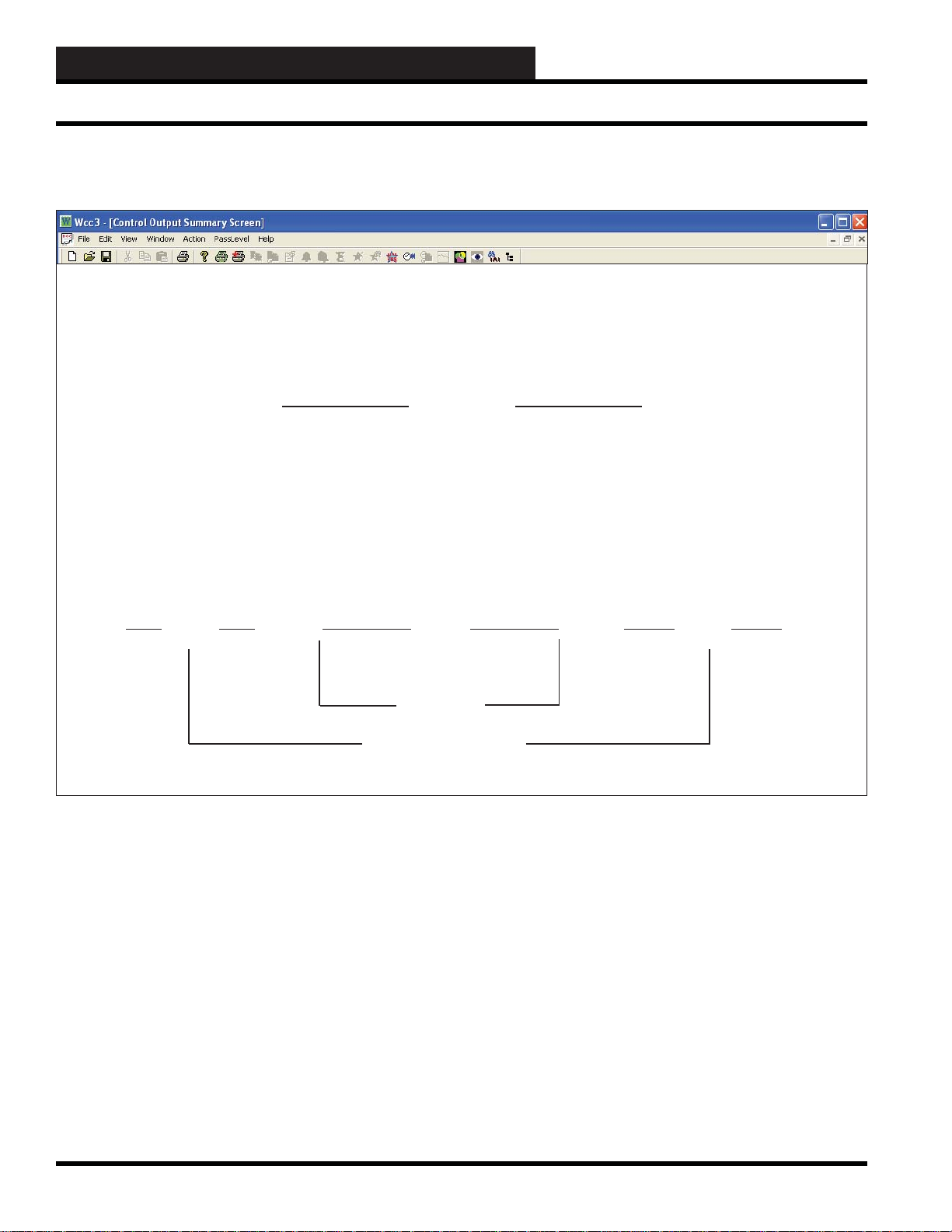
WCC3.EXE SCREEN DESCRIPTIONS
Control Output EA Driver Screen
Control Output Screen’s WCC III Logical Address is XXXKYh or c, where XXX = Satellite Address #, K = Control Output,
Y = Control Output #, h = Heat (General Purpose), and c = Cool (General Purpose)
EA DRIVER SCREEN
Satellite #:_____
Satellite # 1 CONTROL OUTPUT 2 Mode: EA Driver
Description: S1-K2h COM to H on decreasing control signal
Analog Control by: //// COM to C on increasing control signal
Schedule Control by: L1
Setpoints
On Schedule: 0 DEG. Alternate On: 0 Deg F.
Off Schedule: 1 DEG. Off: 0 Deg F
Local Set: 0 DEG. Selected by: ////
Dead Band width: +/- 0 DEG. Reverse Action Selc’d When //// is OFF
Pulse Band width: +/- 0 DEG.
“ “ Off Time: 0 Minutes
“ “ On Time: 3 Minutes
ACTION DIAGRAM
< COM-H > < ALL > < COM-C >
ON PULSED OFF PULSED ON
Setpoint
Dead Band
Pulse Band width
HOME for menu
Specifi es the number of the satellite you are currently editing. If
you would like to edit a different satellite, use the arrow keys to
move the cursor to this fi eld, enter the desired satellite number, and
press <Enter>. 1 to 240.
Control Output _____
This “fi eld” actually contains two separate fi elds. The fi rst fi eld
specifi es the point “type” (i.e., analog input, control output, analog
output, etc.) and displays the current type in textual form. Because
this is a “choice” fi eld, the list of available choices will be displayed
at the bottom of the screen:
<ANALOG INPUT, CONTROL OUTPUT, ANALOG OUTPUT,
TREND LOGGING, LOGIC SWITCH, BINARY OUTPUT>
You may make your selection by pressing the <space bar> until
the desired point type has been selected. If you select a point type
that is different than that currently being displayed, the screen will
be rewritten with the appropriate screen and data.
The second fi eld specifi es the point number to edit. For the Control
Output Screen, this number can range from one to eight. If you
would like to edit a different point, use the arrow keys to move
the cursor to this fi eld, enter the desired point number, and press
<Enter>.
Mode: __________
Specifi es the mode type of the output contact. Because this is a
“choice” fi eld, the list of available choices will be displayed at the
bottom of the screen:
3-54
<Undefi ned, EA Driver, Time Clock, Dual Limit>
WCC III Technical Guide
Page 59

WCC3.EXE SCREEN DESCRIPTIONS
Control Output EA Driver Screen
You make your selection by pressing the <space bar> until the
desired point type appears and then pressing <Enter>. If you select
a mode type that is different than that currently being displayed, the
screen will be rewritten with the appropriate screen information.
Description: ____________
A short message entered here will appear on summary screens to
help you remember points within the system. You may enter up
to ten characters (control codes, ALT codes, and the double quote
character are not allowed).
Analog Control by:
Specifi es the analog point address that acts as the input signal
source for this control output. Analog points within the satellite are
named A1-A8. Global analog values are GA1-GA256. (See Table
of Point Addresses in the General Instructions section on page 1-8
for more information.)
Schedule Control by: ____________
Specifi es the binary (On/Off) point address used to schedule
this control output. When this address is zero (or OFF), the OFF
schedule mode is selected; when it is one (or ON), the ON schedule
mode is selected.
COM to H on decreasing control signal
COM to C on increasing control signal
Displayed by the system as a reminder of the function of the output
contacts in the EA Driver mode. The EA Driver mode uses two of
the SAT III binary output contacts. The COM to H contact closes
when the value of the analog input is less than the setpoint. The
COM to C contact closes when the value of the analog input is
greater than the setpoint.
Schedule Alternate Limits
Control by: Selected by: Setpoint:
On Off On Schedule
On On Alternate On
Off Off Off Schedule
Off On Alternate Off
Dead Band Width (+/-): _______
Pulse Band Width (+/-):_______
Specifi es the width (plus or minus the setpoint) of the Dead and
Pulse bands. When the system is within the Pulse band, the EA
driver is pulsed, using the timing given below. When the system is
within the Dead band, both contacts open and the controlled device
will remain in its present position.
“ “ Off Time: ____ Seconds or Minutes
“ “ On Time: ____ Seconds or Minutes
Specifi es the length of time for the ON and OFF states of the
contact in the Pulse mode. The range is 0 to 60 seconds or minutes,
depending on the unit of time selected. These inputs also act as a
minimum On/Off time for the COM to H and COM to C contacts.
That is, if 10 seconds is entered as the Pulse ON and Pulse OFF
times, once either contact opens it will remain open for a minimum
of 10 seconds, and once a contact closes it will remain closed for a
minimum of 10 seconds.
Because this is a “choice” fi eld, the list of available choices will be
displayed at the bottom of the screen:
< Seconds, Minutes >
You may make your selection by pressing the <space bar> once
for each choice, and when the desired unit of time appears, press
<Enter>.
----------- Setpoints ---------On Schedule: ______ Alternate On: ______
Off Schedule: ______ Off: ______
Local Set: _______ Selected by: ______
Specifi es a set of analog setpoints (5 total) for the ON and OFF
normal mode schedule, ON and OFF alternate mode schedule, and
Local Set.
The value of the input in the Schedule Control by fi eld and the
Alternate Limits Selected by fi eld determine which setpoint will
be used as shown as follows:
WCC III Technical Guide
Rev erse Action Selected When _______is _______
Specifi es the binary point address along with the value that the point
address must have to select reverse action mode. When the reverse
action mode is enabled, the opposite contact closes. Normally, the
COM to C contact closes when the value of the analog input is
above the setpoint, but while the reverse action mode is in effect,
the COM to H contact closes and vice versa.
Because this is a “choice” fi eld, the list of available choices will be
displayed at the bottom of the screen:
<OFF, ON>
You may make your selection by pressing the <space bar> once
for each choice, and when the desired state has been selected, press
<Enter>.:
3-55
Page 60

WCC3.EXE SCREEN DESCRIPTIONS
Control Output Dual Limit Screen
Control Output Screen’s WCC III Logical Address is XXXKYh or c, where XXX = Satellite Address #, K = Control Output,
Y = Control Output #, h = Heat (General Purpose), and c = Cool (General Purpose)
DUAL LIMIT SCREEN
Satellite # 1 CONTROL OUTPUT 1 Mode: Dual Limit
“H” Contact
Description: S1-K1h Contact Open Message #: 2 Off
Analog Control by: //// Contact Closed Message #: 1 On
Schedule Control by: 1 Minimum Off Time: 0 Seconds
Alternate Mode selected by: //// Minimum On Time: 0 Seconds
Override OPEN when 0B2 is OFF Hysteresis: +/- 0 x 1 DEG.
Low Limit Hi Limit
Local Set: OPEN Between 0 & 0 DEG.
On Schedule: OPEN Between 0 & 0 DEG.
Off Schedule: OPEN Between 0 & 0 DEG.
On Schedule: (alt) OPEN Between 0 & 0 DEG.
Off Schedule:(alt) OPEN Between 0 & 0 DEG.
Data Register is measured from Midpoint and Refl ects Hysteresis
HOME for menu
Satellite #: _____
Specifi es the number of the satellite you are currently editing. If
you would like to edit a different satellite, use the arrow keys to
move the cursor to this fi eld, enter the desired satellite number,
and press
Control Output _____
This fi eld actually contains two separate fi elds. The fi rst fi eld
specifi es the point “type” (i.e., analog input, control output, analog
output, etc.) and displays the current type in textual form. Because
this is a “choice” fi eld, the list of available choices will be displayed
at the bottom of the screen:
<ANALOG INPUT, CONTROL OUTPUT, ANALOG OUTPUT,
You may make your selection by pressing the <space bar> once
for each choice, until the desired point type has been selected. (If
you select a point type that is different than that currently being
displayed, the screen will be rewritten with the appropriate screen
and data.) The second fi eld specifi es the point number to edit. For
the Control Output Screen, this number can range from one to
eight. If you would like to edit a different point, simply position
<Enter>.
TREND LOGGING, LOGIC SWITCH, BINARY OUTPUT>
the cursor to this fi eld by using the cursor positioning (arrow) keys,
enter the desired point number, and press
Mode: ____________
Specifi es the mode type of the output contact. Because this is a
“choice” fi eld, the list of available choices will be displayed at the
bottom of the screen:
<Undefi ned, EA Driver, Time Clock, Dual Limit>
You may make your selection by pressing the <space bar> once
for each choice, until the desired point type has been selected, and
then pressing
than that currently being displayed, the screen will be rewritten
with the appropriate screen information.)
_______ Contact
Specifi es which of the two available contacts per point (H or C)
to confi gure. Because this is a “choice” fi eld, the list of available
choices will be displayed at the bottom of the screen:
<Enter>. (If you select a mode type that is different
<Enter>.
<H,C>
3-56
WCC III Technical Guide
Page 61

WCC3.EXE SCREEN DESCRIPTIONS
Control Output Dual Limit Screen
You may make your selection by pressing the <space bar> once
for each choice until the desired point type has been selected and
then pressing <Enter>.
Note that the H and C contact designations do not mean that they
must be used to control heating or cooling loads respectively. They
are independent contacts.
Description: ______________
A short message is entered here which is displayed on Summary
and Data Entry/Editing Screens to help you to remember points
within the system. You may enter up to ten characters (control
codes, ALT codes, and the double quote character are not allowed).
Analog Control by: _______________
Specifi es the analog point address that acts as the input signal
source for this control output.
Schedule Control by: _________________
Specifi es the binary point address used to schedule this control
output. When this address is OFF, the OFF schedule setpoints are
used; when it is ON, the ON schedule setpoints are used.
Alternate Mode Selected by: _________________
Specifi es the binary point address that initiates the Alternate mode.
When this address is zero (or OFF), the Normal mode is selected;
when it is one (or ON), the Alternate mode is selected.
Override __________ when _________ is __________
This fi eld is used to override the satellite contact either open or
closed based on a binary value going ON or OFF . This has priority
over everything except the minimum on and off times.
Override ______
Because this is a “choice” fi eld, the list of available choices will be
displayed at the bottom of the screen:
< CLOSED, OPEN >
is _____
Because this is a “choice” fi eld, the list of available choices will be
displayed at the bottom of the screen:
<OFF, ON>
To make your selection, press the <space bar> once for each
choice until the desired override state has been selected, and then
press <Enter>.
The override is enabled when this statement is true. For example, if
you enter “Override Open When GB1 is ON,” the satellite contact
will be forced open when global binary #1 goes ON.
Contact Open Message #: ____
Contact Closed Message #: ____
Specifi es a pair of message numbers, one for the contact open state
and the second for the contact closed state. These numbers refer to
a message on the On/Off Message Screen. For example, message
#1 might be “Fan On” and message #2 “Fan Off.” If you want the
message on the Control Output Summary Screen to be “Fan On”
when the satellite contact is closed, enter “#1” as the contact closed
message etc.
Minimum Off Time: ____ seconds
Minimum On Time: ____ seconds
Specifi es the minimum ON and OFF times for switching a load
to its opposite state (i.e., ON to OFF or OFF to ON). That is, once
the satellite contact closes it will remain closed for the minimum
ON time, and once it opens it will remain open for the minimum
OFF time. The range is 0 to 60 seconds or minutes, depending on
the unit of time selected. Because this is a “choice” fi eld, the list of
available choices will be displayed at the bottom of the screen:
<Seconds, Minutes>
To make your selection, press the <space bar> once for each
choice, and when the desired unit of time appears, press <Enter>.
Note that the minimum ON and OFF time has precedence over
demand limiting, overrides, etc.
Closed means that the satellite contact will be forced closed when
the override statement is true. Open means the satellite contact
will be forced open. To make your selection, press the <space
bar> once for each choice until the desired override state has been
selected, and then press <Enter>.
When _____
This is where you enter a binary value.
WCC III Technical Guide
Hysteresis: = _____ x 0.1
Hysteresis is a software entry that allows an operator to specify
how much a measure variable, such as room temperature, has to
change before the switch changes state. For example, consider
a temperature setpoint of 72 °F with a +/-0.5 °F hysteresis. The
switch will change state (open/close) when the temperature rises
to 72.5 °F and will not switch back to its original state until the
temperature drops to 71.5 °F .
3-57
Page 62

WCC3.EXE SCREEN DESCRIPTIONS
Control Output Dual Limit Screen
The multiplier is automatically selected based on the data pattern
for the analog input associated with this screen. If the data pattern
is xxx.x, then 0.1 will appear as the multiplier. If a +/-0.5 hysteresis
is desired, input 5, and the system will multiply 5 by 0.1 to equal
0.5.
Low Limit High Limit
Local Set _______ Between_______ & _______
On Schedule _______ Between_______ & _______
Off Schedule _______ Between_______ & _______
On Schedule (Alt)____ Between_______ & _______
Off Schedule (Alt)_____Between_______ & _______
This group of inputs specifi es the setpoints for the “Local Set,”
“Normal,” and “Alternate” modes.
The “Local Set” setpoints are selected whenever the front end
computer quits communicating with the satellite controller.
The value of the input in the Schedule Control by fi eld and the
Alternate Mode Selected by fi eld determine which setpoints will
be used as shown below:
Schedule Alternate Mode
Control by: Selected by: Setpoint
On Off On Schedule
On On On Schedule (Alt)
Off Off Off Schedule
Off On Off Schedule (Alt)
In the fi rst fi eld you specify whether you want the satellite contact
to “Open” or “Close” when the value of the analog input is between
the limits. Because this is a “choice” fi eld, the list of available
choices will be displayed at the bottom of the screen:
<CLOSED, OPEN>
You may make your selection by pressing the <space bar> until
the desired contact state appears and then pressing <Enter>.
If you have an application where you want the low limit to be
negative infi nity, input the slash (/) for the low limit value. The
system will show a series of minus signs as the (-----) setpoint. In
the same manner, if you want the high limit to be positive infi nity,
input the slash (/) as the high limit value. The system will show a
series of plus signs (+++++) as the input value.
Data register is measured from ______ and ______
Hysteresis.
For the phrase: “Data register is measured from ...”
<Midpoint, Nearest Limit>
and for the phrase: “and __________ Hysteresis.”
<Ignores, Refl ects>
You may make your selection by pressing the <space bar> until
the desired defi nition appears and then pressing
<Enter>.
If “Midpoint” is selected, the value of the data register will be the
difference between the actual value of the analog input associated
with this screen, such as room temperature, and the midpoint
between the two setpoints.
If “Nearest Limit” is selected, the value of the data register will
be the difference between the actual value of the analog input
associated with this screen, such as room temperature, and the
nearest setpoint.
See the Data Register write-up in the General Instructions section
of this guide on page 1-9 for more information.
Logical Off is “ . . . . . “
This means that this value is Off and has no schedule control. This
value can be overridden on the Override Schedules Screen. Same
as “0”.
Null Value is “ / / / / “
This means that this value is neither On nor Off, but can also
be On or Off in certain circumstances. It is best not to leave the
Null Values in place. This value CANNOT be overridden on the
Override Schedules Screen. This value can also mean negative
infi nity.
3-58
WCC III Technical Guide
Page 63

WCC3.EXE SCREEN DESCRIPTIONS
Control Output Time Clock Screen
Control Output Screen’s WCC III Logical Address is XXXKYh or c, where XXX = Satellite Address #, K = Control Output,
Y = Control Output #, h = Heat (General Purpose), and c = Cool (General Purpose)
TIME CLOCK SCREEN
Satellite # 1 CONTROL OUTPUT #__1 Mode: Time Clock
“H” Contact
Description: S1-K1h Contact Open Message #: 2 Lght Off
Contact Closed Message #: 1 Lght On
Minimum Off Time: 0 Seconds
Minimum On Time: 0 Seconds
Contact is: CLOSED in “On” Schedule Selected by: 1
OPEN in Primary Alternate Mode Selected by: ////
OPEN in Secondary Alternate Mode Selected by: ////
OPEN in Local Set
HOME for menu
Satellite #: ____
Specifi es the number of the satellite you are currently editing.
If you would like to edit a different satellite, simply position the
cursor to this fi eld by using the cursor positioning (arrow) keys,
enter the desired satellite number, and press
Control Output ____
This fi eld actually contains two separate fi elds. The fi rst fi eld
specifi es the point “type” (i.e., analog input, control output, analog
output, etc.) and displays the current type in textual form. Because
this is a “choice” fi eld, the list of available choices will be displayed
at the bottom of the screen:
<ANALOG INPUT, CONTROL OUTPUT, ANALOG OUTPUT,
TREND LOGGING, LOGIC SWITCH, BINARY OUTPUT>
You may make your selection by pressing the <space bar> once
for each choice, until the desired point type has been selected. (If
you select a point type that is different than that currently being
displayed, the screen will be rewritten with the appropriate screen
and data.) The second fi eld specifi es the point number to edit. For
the Control Output Screen, this number can range from one to
eight. If you would like to edit a different point, simply position
the cursor to this fi eld by using the cursor positioning (arrow) keys,
enter the desired point number, and press
<Enter>.
<Enter>.
Mode: ______________
Specifi es the mode type of the currently specifi ed contact. Because
this is a “choice” fi eld, the list of available choices will be displayed
at the bottom of the screen:
<Undefi ned, EA Driver, Time Clock, Dual Limit>
To make your selection, press the <space bar> once for each
choice until the desired point type has been selected, and then
press
<Enter>. (If you select a mode type that is different than
that currently being displayed, the screen will be rewritten with the
appropriate screen information.)
______ Contact
Specifi es which of the two available contacts per point (H or C)
to confi gure. Because this is a “choice” fi eld, the list of available
choices will be displayed at the bottom of the screen:
< H,C >
Make your selection by pressing the <space bar> once for each
choice until the desired point type has been selected, and then press
<Enter>.
Note that the H and C contact designations do not mean that
the contacts must be used to control heating or cooling loads,
respectively. They are independent contacts.
WCC III Technical Guide
3-59
Page 64

WCC3.EXE SCREEN DESCRIPTIONS
Control Output Time Clock Screen
Description: _____________
A short message is entered here which will be displayed on Summary
and Data Entry/Editing Screens to aid you in remembering points
within the system. You may enter up to ten characters (control
codes, ALT codes, and the double quote character are not allowed).
Contact Open Message #: ____
Contact Closed Message #: ____
Specifi es a pair of message numbers, the fi rst for the contact open
state and the second for the contact closed state. These numbers
refer to a message on the On/Off Message Screen. For example,
message #1 might be “Fan On” and message #2 “Fan Off.” If
you want the message on the Control Output Summary Screen to
be “Fan On” when the satellite contact is closed, enter “#1” as the
contact closed message etc.
Minimum Off Time: _____ seconds
Minimum On Time: _____ seconds
Specifi es the minimum ON and OFF times for switching a load
to its opposite state (i.e., ON to OFF or OFF to ON). That is, once
the satellite contact closes it will remain closed for the minimum
ON time, and once it opens it will remain open for the minimum
OFF time. The range is 0 to 60 seconds or minutes, depending on
the unit of time selected. Because this is a “choice” fi eld, the list
of available choices will be displayed at the bottom of the screen:
<Seconds, Minutes>
Make your selection by pressing the <space bar> once for each
choice, and when the desired unit of time appears, press the
<Enter> key.
Contact is:
_________in “On” Schedule Selected by:________
_________in Primary Alt Mode Selected by:________
_________in Secondary Alt Mode Selected by:________
_________in Local Set Selected by:________
The fi rst fi eld specifi es whether the satellite contact is to Open or
Close when the binary value entered in its Selected by fi eld goes
On.
The Primary Alt mode has highest priority, followed by Secondary
Alternate, and then On Schedule.
Since the fi rst fi eld is a “choice” fi eld, the list of available choices
will be displayed at the bottom of the screen:
<OPEN, CLOSED>
On the “On” schedule
< OPEN, CLOSED, HOLD LAST >
On the Primary Alt Mode, Secondary Alt Mode, and Local Set
Make your selection by pressing the
<space bar> once for each
choice until the desired contact state has been selected, and then
press <Enter>.
Note that the HOLD LAST is available for Primary Alt,
Secondary Alt and Local Set modes only. If
HOLD LAST is
selected in the Local Set mode, the contact will stay closed if
it was closed at the time the satellite went into local set or will
stay open if it was open when the satellite went into local set.
Note that the minimum ON and OFF time has precedence over
demand limiting, overrides, etc.
3-60
WCC III Technical Guide
Page 65

WCC3.EXE SCREEN DESCRIPTIONS
Control Output Time Clock Screen
WCC III Technical Guide
3-61
Page 66

WCC3.EXE SCREEN DESCRIPTIONS
Control Output Time Clock Screen
3-62
WCC III Technical Guide
Page 67

WCC3.EXE SCREEN DESCRIPTIONS
Analog Output Summary Screen
Analog Output Screen’s WCC III Logical Address is XXXPY, where XXX = Satellite Address #,
P = Analog Output, Y = Analog Output #
ANALOG OUTPUT SUMMAR Y SCREEN
Analog Output Satellite # 1 Sat. #1 Time Date
08:53 1/20
Analog Outputs
COMMENTS STATUS MODE CURRENT INPUT INPUT RANGE OUTPUT RANGE
P1: P1 10.0 V alt 99.0 Deg F 20.0 - 80.0 5.0 - 10.0 V
P2: P1 10.0 V alt 99.0 Deg F 20.0 - 80.0 5.0 - 10.0 V
P3: P1 10.7 V alt 99.0 Deg F 20.0 - 80.0 5.0 - 10.0 V
P4: V alt
P5: V alt
P6: P1 5.0 V alt 9.0 Deg F 20.0 - 80.0 5.0 - 10.0 V
P7: P1 5.0 V alt 9.0 Deg F 20.0 - 80.0 5.0 - 10.0 V
P8: P1 5.0 V alt 9.0 Deg F 40.0 - 80.0 5.0 - 10.0 V
HOME for menu
An analog output is a proportional DC voltage supplied by the
SAT III with a maximum range of 0-15 VDC. The analog outputs
are proportional only, not proportional plus integral (PI), or
proportional plus integral plus derivative (PID).
Analog Out
Specifi es the summary type to be displayed. Because this is a
“choice” fi eld, the list of available choices will be displayed at the
bottom of the screen.
<Analog Input, Control Output, Analog Output,
Trend Logging, Logic Switch, Binary Output>
Make your selection by pressing the <space bar> until the desired
summary type has been selected, and then press
select a summary type that is different than that currently being
displayed, the screen will be rewritten with the new information.
Satellite ______
Specifi es the number of the satellite which you are currently
communicating with. If you would like to view the analog output
summary data for a different satellite, use the arrow keys to
move the cursor to this fi eld, enter the desired number, and press
<Enter>.
<Enter>. If you
T o view or edit a specifi c analog output, use the arrow keys to move
the cursor (shown as “>” along the left hand side of the screen) to
the desired point, and press
for the specifi ed point will appear.
Time / Date
The current time and date will automatically be displayed here.
COMMENTS
The description message which is entered on the individual Analog
Output Screens will automatically appear here to help you identify
the different analog outputs within the system.
STATUS
The amount of DC voltage supplied by the analog output is shown
here to help you monitor the status of the analog output.
<Enter>. The Analog Output Screen
WCC III Technical Guide
3-63
Page 68

WCC3.EXE SCREEN DESCRIPTIONS
Analog Output Summary Screen
MODE
An “alt” message may be displayed in this column to inform you
that analog output is in its alternate mode. When the status of the
binary input which has been entered on the analog output screen to
select the alternate mode is “ON,” the alternate control limits are
used, and the “alt” message is shown here.
CURRENT INPUT
The value of the analog input associated with the Analog Output
Screen is automatically displayed here. For example, if you are
controlling a chilled water valve based on supply air temperature,
the supply air temperature will be shown here.
INPUT RANGE OUTPUT RANGE
You specify an output voltage for a given analog input signal on
the Analog Output Screen. The values which are input on the
analog output screen are shown here. For example, if you input the
following ranges on the Analog Output Screen:
Output = 0.0 volts when input is 50.0 °F
Output = 15.0 volts when input is 60.0 °F
The Summary Screen would look like this:
INPUT RANGE OUTPUT RANGE
50.0 - 60.0 0.0 - 15.0 V
3-64
WCC III Technical Guide
Page 69

WCC3.EXE SCREEN DESCRIPTIONS
Analog Output Screen’s WCC III Logical Address is XXXPY, where XXX = Satellite Address #,
P = Analog Output, Y = Analog Output #
ANALOG OUTPUT SCREEN
Satellite # 1 ANALOG OUTPUT # 2
Description: P1
Filter time constant: 0 seconds
Controlled by input: A1
Output = 5.0 volts when input is 20.0 Deg F
Output = 10.0 volts when input is 80.0 Deg F
Alternate Mode selected by:
Analog Output Screen
Selected by: ....
Output = 0.0 volts when input is 0.0 Deg F
Output = 0.0 volts when input is 0.0 Deg F
When calculated output below 5.0 volts, set output to 5.0 volts
When calculated output above 10.0 volts, set output to 10.0 volts
HOME for menu
Satellite # _____
Specifi es the number of the satellite you are currently editing. If
you would like to edit a different satellite, move the cursor to this
fi eld using arrow keys, enter the desired satellite number, and press
<Enter>. 1 to 239.
Analog Output #_____
This fi eld actually contains two separate fi elds. The fi rst fi eld
specifi es the point “type” (i.e., analog input, control output, analog
output, etc.) and displays the current type in textual form. Because
this is a “choice” fi eld, the list of available choices will be displayed
at the bottom of the screen:
This second fi eld specifi es the point number to edit. For the
Analog Output Screen, this number can range from one to eight,
corresponding from P1 to P8, respectively. If you would like to
edit a different point, simply position the cursor to this fi eld by
using the cursor positioning (arrow) keys, enter the desired point
number, and press
Description
This is displayed on Summary and Data Entry/Editing Screens to
aid you in remembering points within the system. You may enter
up to ten characters (control codes, ALT codes, and the double
quote character are not allowed).
<Enter>.
<ANALOG INPUT, CONTROL OUTPUT, ANALOG OUTPUT,
TREND LOGGING, LOGIC SWITCH, BINARY OUTPUT>
Make your selection by pressing the <space bar> once for each
choice until the desired point type has been selected. (If you select
a point type that is different than that currently being displayed, the
screen will be rewritten with the appropriate screen and data.)
WCC III Technical Guide
Filter Time Constant: _____ seconds
Specifi es the reaction rate of the analog output. This is generally
used to slow down the rate at which the analog output changes
voltage to reduce “hunting.”
Because this is a “choice” fi eld, the list of available choices will be
displayed at the bottom of the screen:
< 0, 1, 2, 4, 8, 16, 32, 64 >
3-65
Page 70

WCC3.EXE SCREEN DESCRIPTIONS
Analog Output Screen
To make your selection, press the <space bar> once for each
choice until the desired fi lter time constant has been selected, and
then press <Enter>.
Controlled by input:
Specifi es the [analog] point address that acts as the input signal
source for the control range specifi ed. The output voltage is
proportional to the value of this input.
Output = ___._ volts when input is _____
Output = ___._ volts when input is _____
Specifi es the output voltage range for a given analog input signal.
The maximum output range is 0 to 15 volts D.C., and may be
specifi ed in such a way as to allow a proportional (direct acting)
or an inversely proportional (reverse acting) output voltage.
(Alternate and normal modes each have an output voltage range
specifi cation.)
For example, if
Output = 0.0 volts when input is 72 °F
Output = 15.0 volts when input is 76 °F
is used, the output will range from 0 to 15 volts when the input
signal is from 72 °F to 76 °F . If the input signal is less than 72 °F or
greater than 76 °F , the output will be 0 and 15 volts, respectively.
Selected by:
Specifi es the [binary] point address that initiates the Alternate
mode. When this address is zero (or OFF), the Normal output
range is selected; when it is one (or ON), the Alternate output range
is selected.
When calculated output below xx.x volts, set output
to xx.x volts
When calculated output above xx.x volts, set output
to xx.x volts
This fi eld allows you to enter a defi ned range for output voltage.
When the calculated output falls below a determined voltage, set
the output to a defi ned voltage. When the calculated output goes
past a determined voltage, set the output to a defi ned voltage.
3-66
WCC III Technical Guide
Page 71

WCC3.EXE SCREEN DESCRIPTIONS
Analog Output Screen
WCC III Technical Guide
3-67
Page 72

WCC3.EXE SCREEN DESCRIPTIONS
WCC III System Logging
WCC III SY STEM LOGGING
Additional WCC III system long-term trend logging is available
with the WCC3Trendlog.exe program. Any of the following point
addresses can be trend logged:
Satellite Binary Inputs
Satellite Analog Inputs
Satellite Analog Outputs
Satellite Binary Outputs
Satellite Control Outputs H Contact
Satellite Control Outputs C Contact
Satellite Data Register A
Satellite Data Register B
Satellite Run Times
Satellite Logic Switch
WCC Global Analog
WCC Global Binary
WCC W eek Schedule
WCC Optimal Start
SA T TREND LOGGING
The WCC III system SAT III Controller has four trend modes
described below. A SAT cannot trendlog another SAT Analog or
Binary Control Point. The Satellite Controller can only trendlog
its own inputs and output. Week Schedules, Global Binary, Global
Analog, and Optimal Starts can be trendlogged on any Satellite
Controller.
SA T Change of State
A trend logging mode which records any changes of state (i.e.
“OFF” going to “ON” or “ON” going to “OFF”) of a binary value
along with the time and date of the change. Acceptable values are
0, 1, GBXXX, KXh, KXc, WXX, SX, OXX, LXX, CX.
SAT Run Time Total
A trend logging feature which allows the WCC III to accumulate
the amount of time a binary value has been “ON” or “OFF.”
Acceptable values are 0, 1, GBXXX, KXh, KXc, WXX, SX,
OXX, LXX, CX.
SAT Analog T rend
A trend logging mode which records the value of a measured
variable, such as room temperature, at programmed time intervals.
Acceptable values are AX, PX, GAXXX, RXA, RXB.
The WCC3 Trendlog.exe program allows that any of these points
can be charted and graphed and saved. There is an additional option
to save this data fi le as an ODBC database type fi le structure for
viewing in MS Access, Excel, or any other third party database
program that uses ODBC formatting.
SA T Analog Peak
A trend logging mode which records the highest and lowest value
of a measured variable along with the time and the date that the
peak occurred. Acceptable values are AX, PX, GAXXX, RXA,
RXB.
3-68
WCC III Technical Guide
Page 73

WCC3.EXE SCREEN DESCRIPTIONS
SA T Trend Log Summary Screen
Satellite Trend Log Summary Screen’s WCC III Logical Address is XXXTYc, where XXX = Satellite Address #, T = Trend Log,
Y = Point Number, c = Change of State
SA T TREND LOG SUMMAR Y SCREEN
Trend Logging Satellite # 1 Sat.#1 Time Date
09:08 01/20
CHANGE OF STATE RUN TIME TOTAL
Point Description Last change Point Description Current Val Alarm Limit
T1c: S1-K1h 16:23 12/09 T1r: S1-K1h 1870 Hours 5000 Hours
T2c: S1-K2h 8:33 12/10 T2r: S1-K2h 868 Hours 5000 Hours
T3c: S1-K3h 16:23 12/09 T3r: S1-K3h 1870 Hours 5000 Hours
T4c: S1-K4h 16:23 12/09 T4r: S1-K4h 1870 Hours 5000 Hours
T5c: S1-K5h 16:23 12/09 T5r: S1-K5h 1870 Hours 5000 Hours
T6c: S1-K6h 08:59 01/12 T6r: S1-K6h 1678 Hours 5000 Hours
T7c: S1-K7h 16:23 12/09 T7r: S1-K7h 1870 Hours 5000 Hours
T8c: S1-K8h 16:23 12/09 T8r: S1-K8h 1870 Hours 5000 Hours
ANALOG TREND ANALOG PEAK
Point Description Last Sample Point Description Low High Units
T1a: S1-A1 50.0 Deg F T1p: S1-A1 0.0 50.0 Deg. F
T2a: S1-A2 0 Deg. F T2p: S1-A2 0.0 0.0 Deg. F
T3a: S1-A3 0 Deg. F T3p: S1-A3 0.0 0.0 Deg. F
T4a: S1-A4 0 Deg. F T4p: S1-A4 0.0 0.0 Deg. F
T5a: S1-A5 0 Deg. F T5p: S1-A5 0.0 0.0 Deg. F
T6a: S1-A6 0 Deg. F T6p: S1-A6 0.0 0.0 Deg. F
T7a: S1-A7 9.0 Deg. F T7p: S1-A7 0.0 9.0 Deg. F
T8a: S1-A8 99.0 Deg. F T8p: S1-A8 0.0 99.0 Deg. F
SAT Trend Log
Specifi es the summary type to be displayed. Because this is a
“choice” fi eld, the list of available choices will be displayed at the
bottom of the screen:
<Analog Input, Control Output, Analog Output,
Trend Logging, Logic Switch, Binary Output>
Time / Date
The present time and date will automatically appear at these
locations.
Point
The system automatically displays the “name” of each of the trend
log points.
Make your selection by pressing the <space bar> once for each
choice until the desired summary type has been selected, and then
press <Enter>. (If you select a summary type that is different
than that being displayed, the screen will be rewritten with the
appropriate information.)
T = Trend Log
1 - 8 = The number of the trend log
c = Change of State
r = Run T ime
a = Analog T rend
p = Analog Peak
Satellite ______
Description
Specifi es the number of the satellite which you are currently
communicating with. If you would like to view the trend log
summary data for a different satellite, simply position the cursor to
this fi eld using the arrow keys, enter the desired number, and press
<Enter>. To view or edit a specifi c trend log, simply position the
cursor (shown as “>“) using the arrow keys to the desired point,
and press <Enter>. The Trend Log Screen for the desired point
will appear.
The message which is entered on the specifi c Trend Logging
Screen is automatically displayed here to help you identify the
different trend logs within the system.
Each of the trend log modes have a heading such a “Last Change,”
“Current Value,” etc. The most recent value of the individual trend
logs will automatically be displayed here.
WCC III Technical Guide
3-69
Page 74

WCC3.EXE SCREEN DESCRIPTIONS
SA T Change of State T rend Log Screen
Satellite Trend Log Summary Screen’s WCC III Logical Address is XXXTYc, where XXX = Satellite Address #, T = Trend Log,
Y = Point Number, c = Change of State
SA T CHANGE OF STA TE TREND LOG SCREEN
Satellite # 1 TREND LOGGING # 1 of Type: CHANGE OF STATE
Records time & date of Starting at: *:* on */*
state changes on: K1h S1-K1h Reset by: //// being ON
Roll after 48 readings
Off --- 0. 10:01 12/01
On --- 1. 10:04 12/01
Off --- 2. 00:00 00/00
On --- 3. 10:55 12/09
Off --- 4. 00:00 00/00
Satellite #: _____
Specifi es the number of the satellite you are currently editing.
If you would like to edit a different satellite, simply position the
cursor to this fi eld by using the cursor positioning (arrow) keys,
enter the desired satellite number, and press
Trend Log #: ____
<Enter>.
This fi eld actually contains two separate fi elds. The fi rst fi eld
specifi es the point “type” (i.e., analog input, control output, analog
output, etc.) and displays the current type in textual form. Because
this is a “choice” fi eld, the list of available choices will be displayed
at the bottom of the screen:
<ANALOG INPUT, CONTROL OUTPUT, ANALOG OUTPUT,
TREND LOGGING, LOGIC SWITCH, BINARY OUTPUT>
Make your selection by pressing the <space bar> once for each
choice until the desired mode has been selected, and then press
<Enter>. (If you select a point type that is different than that
currently being displayed, the screen will be rewritten with the
appropriate screen and data.)
The second fi eld specifi es the point number to edit. For the Trend
Log Screen, this number can range from one to eight. If you would
like to edit a different point, simply position the cursor to this fi eld
by using the cursor positioning (arrow) keys, enter the desired
point number, and press
<Enter>.
Make your selection by pressing the <space bar> once for each
choice until the desired mode has been selected, and then press
<Enter>. (When you select a trend logging mode that is different
than that currently being displayed, the screen will be rewritten
with the appropriate screen and data.)
Record time & date of state change on: ________
Specifi es the [binary] point address for which the change-of-states
are to be recorded.
Starting at: 00:00 on 00/00
Specifi es the time and date that the trend log recording should
begin. (The time is represented in 24-hour format.) The system
considers *’s in these positions to be “wild cards.” Therefore, if
you want the system to always log the changes-of-state peaks
independent of the time and date, enter “*:* on */*.”
Reset by _________ being _____.
Specifi es the [binary] point address that will be used to reset (or
clear) the record trend log data. The fi rst fi eld specifi es the point
address, and the second specifi es the state or condition that the point
address needs to be in to clear the data. Because this second fi eld
is a “choice” fi eld, the list of available choices will be displayed at
the bottom of the screen:
<OFF, ON>
of Type
Specifi es which of the four available trend logging modes (analog
peak, analog trend, change-of-state, and run time) you wish to use.
Because this is a “choice” fi eld, the list of available choices will be
displayed at the bottom of the screen:
<ANALOG TREND, ANALOG PEAK,
CHANGE OF STATE, RUN TIME>
3-70
_________ after 48 readings
Specifi es whether the data logging process will stop after 48
readings have been taken or will continue (roll over). Because this
is a “choice” fi eld, the list of available choices will be displayed at
the bottom of the screen:
<Stop, Roll>
WCC III Technical Guide
Page 75

WCC3.EXE SCREEN DESCRIPTIONS
SA T Run Time T rend Log Screen
Satellite Trend Log Summary Screen’s WCC III Logical Address is XXXTYr, where XXX = Satellite Address #, T = Trend Log, Y
= Point Number, r = Run Time
SA T RUN TIME TREND LOG SCREEN
Satellite # 1 TREND LOGGING # 1 of Type: RUN TIME
Records total ON time Starting at : *:* on */*
for Klh S1-Kh Reset by: //// being ON
Alarm Type: 0
Alarm Message #: 0
Current run time: 1871 Hours Alarm Limit: 9999 Hours
HOME for menu
Satellite #: _____
Specifi es the number of the satellite you are currently editing.
If you would like to edit a different satellite, simply position the
cursor to this fi eld by using the cursor positioning (arrow) keys,
enter the desired satellite number, and press <Enter>.
Trend Log #: ____
This fi eld actually contains two separate fi elds. The fi rst fi eld
specifi es the point “type” (i.e., analog input, control output, analog
output, etc.) and displays the current type in textual form. Because
this is a “choice” fi eld, the list of available choices will be displayed
at the bottom of the screen:
<ANALOG INPUT, CONTROL OUTPUT, ANALOG OUTPUT,
TREND LOGGING, LOGIC SWITCH, BINARY OUTPUT>
Make your selection by pressing the <space bar> once for each
choice until the desired point type has been selected and then
press <Enter>. (If you select a point type that is different than that
currently being displayed, the screen will be rewritten with the
appropriate screen and data.)
The second fi eld specifi es the point number to edit. For the Trend
Log Screen, this number can range from one to eight. If you would
like to edit a different point, simply position the cursor to this fi eld
by using the cursor positioning (arrow) keys, enter the desired
point number, and press
<Enter>.
of Type
Specifi es which of the four available trend logging modes (analog
peak, analog trend, change-of-state, and run time) you wish to use.
Because this is a “choice” fi eld, the list of available choices will be
displayed at the bottom of the screen:
<ANALOG TREND, ANALOG PEAK, CHANGE OF STATE,
RUN TIME>
Make your selection by pressing the <space bar> once for each
choice until the desired mode has been selected, and then press
<Enter>. (When you select a trend logging mode that is different
than that currently being displayed, the screen will be rewritten
with the appropriate screen and data.)
Records total ____ time for: ______
Specifi es the state (ON or OFF) and the [binary] point address for
which the run time is to be recorded. Because the state fi eld is a
“choice” fi eld, the list of available choices will be displayed at the
bottom of the screen:
<OFF, ON>
Make your selection by pressing the <space bar> once for each
choice until the desired state has been selected, and then press
<Enter>.
WCC III Technical Guide
3-71
Page 76

WCC3.EXE SCREEN DESCRIPTIONS
SA T Run Time T rend Log Screen
Current run time: _____ seconds
This is the current accumulated run time. You may select the
units of time by positioning the cursor after the current run time.
Because this is a “choice” fi eld, the list of available choices will be
displayed at the bottom of the screen:
<Hours, Seconds, Minutes>
Make your selection by pressing the <space bar> once for each
choice until the desired state has been selected, and then press
<Enter>.
Starting at: 00:00 on 00/00
Specifi es the time and date that the trend log recording should
begin. (The time is represented in 24-hour format.) The system
considers *’s in these positions to be “wild cards.” Therefore, if
you want the system to log the run time independent of the time
and date, enter “*:* on */*.”
Reset by _______ being ____.
Specifi es the [binary] point address that will be used to reset (or
clear) the record trend log data. The fi rst fi eld specifi es the point
address, and the second specifi es the state or condition that the point
address needs to be in to clear the data. Because this second fi eld
is a “choice” fi eld, the list of available choices will be displayed at
the bottom of the screen:
<OFF, ON>
Make your selection by pressing the <space bar> once for each
choice until the desired state has been selected, and then press
<Enter>.
Alarm Type: _____
Specifi es the priority (or “importance level”) for any alarms
generated by this input. Alarm types range from one (high priority)
to eight (low priority). The system responds to higher priority
alarms fi rst.
Alarm Message #: _____
Specifi es a message number for the run time alarm condition. This
number is used by the system to reference a textual message which
is displayed on the Alarm Summary Screen.
Alarm Limit: ____ seconds
Specifi es a time limit at which point an alarm will be activated. That
is, when the total run time exceeds this limit, an alarm indication
will be sent from the satellite. The units of time will be the same as
that selected for the current run time.
3-72
WCC III Technical Guide
Page 77

WCC3.EXE SCREEN DESCRIPTIONS
SA T Analog Trend T rend Log Screen
Satellite Trend Log Summary Screen’s WCC III Logical Address is XXXTYa, where XXX = Satellite Address #, T = Trend Log,
Y = Point Number, a = Analog Trend
SA T ANALOG TREND TREND LOG SCREEN
Satellite # 1 TREND LOGGING # 1 of Type: ANALOG TREND
Records value of: A1 S1-A1 Starting at: *:* on */*
once every: 15 Minutes Reset by: .... being ON
Roll after 48 readings
21:53 1/19 50.0 01:53 1/20 50.0 06:08 1/20 50.0
22:08 1/19 50.0 02:08 1/20 50.0 06:23 1/20 50.0
22:23 1/19 50.0 02:23 1/20 50.0 06:38 1/20 50.0
22:38 1/19 50.0 02:38 1/20 50.0 06:53 1/20 50.0
22:53 1/19 50.0 02:53 1/20 50.0 07:08 1/20 50.0
23:08 1/19 50.0 03:08 1/20 50.0 07:23 1/20 50.0
23:23 1/19 50.0 03:23 1/20 50.0 07:38 1/20 50.0
23:38 1/19 50.0 03:38 1/20 50.0 07:53 1/20 50.0
23:53 1/19 50.0 03:53 1/20 50.0 08:08 1/20 50.0
00:08 1/19 50.0 04:08 1/20 50.0 08:23 1/20 50.0
00:23 1/19 50.0 04:23 1/20 50.0 08:38 1/20 50.0
00:38 1/19 50.0 04:38 1/20 50.0 08:53 1/20 50.0
00:53 1/19 50.0 04:53 1/20 50.0 09:08 1/20 50.0
01:08 1/19 50.0 05:08 1/20 50.0 09:23 1/20 50.0
01:23 1/19 50.0 05:23 1/20 50.0 09:38 1/20 50.0
01:38 1/19 50.0 05:38 1/20 50.0 09:53 1/20 50.0
HOME for menu
Satellite #: ____
Specifi es the number of the satellite you are currently editing.
If you would like to edit a different satellite, simply position the
cursor to this fi eld by using the cursor positioning (arrow) keys,
enter the desired satellite number, and press
Trend Log #: ____
This fi eld actually contains two separate fi elds. The fi rst fi eld
specifi es the point “type” (i.e., analog input, control output, analog
output, etc.) and displays the current type in textual form. Because
this is a “choice” fi eld, the list of available choices will be displayed
at the bottom of the screen:
<ANALOG INPUT, CONTROL OUTPUT, ANALOG OUTPUT,
TREND LOGGING, LOGIC SWITCH, BINARY OUTPUT>
Make your selection by pressing the <space bar> once for each
choice until the desired point type has been selected and then
press
<Enter>. (If you select a point type that is different than that
currently being displayed, the screen will be rewritten with the
appropriate screen and data.)
<Enter>.
WCC III Technical Guide
The second fi eld specifi es the point number to edit. For the Trend
Log Screen, this number can range from one to eight. If you would
like to edit a different point, simply position the cursor to this fi eld
by using the cursor positioning (arrow) keys, enter the desired
point number, and press
of Type:
Specifi es which of the four available trend logging modes (analog
peak, analog trend, change-of-state, and run time) you wish to use.
Because this is a “choice” fi eld, the list of available choices will be
displayed at the bottom of the screen:
<ANALOG TREND, ANALOG PEAK, CHANGE OF STATE,
Make your selection by pressing the <space bar> once for each
choice until the desired mode has been selected, and then press
<Enter>. (When you select a trend logging mode that is different
than that currently being displayed, the screen will be rewritten
with the appropriate screen and data.)
<Enter>.
RUN TIME>
3-73
Page 78

WCC3.EXE SCREEN DESCRIPTIONS
SA T Analog Trend T rend Log Screen
Record value of: ______once every _____ minutes
Specifi es the [analog] point address for which the analog trend is
to be recorded. Also specifi es the time interval between samples
in either minutes or hours. Because this is a “choice” fi eld, the list
of available choices will be displayed at the bottom of the screen:
<Minutes, Hours>
Make your selection by pressing the <space bar> once for each
choice until the desired units of time have been selected.
Starting at: 00:00 on 00/00
Specifi es the time and date that the trend log recording should
begin. (The time is represented in 24-hour format.) The system
considers *’s in these positions to be “wild cards.” Therefore, if you
want the system to always log the analog trend values independent
of the time, enter “*:* on */*.”
Reset by ___________ being _______
Specifi es the [binary] point address that will be used to reset (or
clear) the record trend log data. The fi rst fi eld specifi es the point
address, and the second specifi es the state or condition that the
point address needs to be in to clear the data. Because this second
fi eld is a “choice” fi eld, the list of available choices will be
displayed at the bottom of the screen:
_______ after 48 readings
Specifi es whether the data logging process will stop after 48
readings have been taken or will continue (roll over). Because this
is a “choice” fi eld, the list of available choices will be displayed at
the bottom of the screen:
<Stop, Roll>
Trend Log Graph
The Analog Trend Screen has a graph which can be accessed by
pressing
<Plot> or by pressing <Ctrl><G>. A graph which shows the value
<Alt> <A> to access the Action Menu and then selecting
of the analog global versus time should appear on the screen. If
the WCC III system is “re-painting” the screen at the moment you
access the graph, the full graph will not be displayed. To make
sure that you get a full graph on the screen, move the cursor to the
“Home” position on the screen. Press the
<Home> key to return to
the Analog Trend Screen.
<OFF, ON>
3-74
WCC III Technical Guide
Page 79

WCC3.EXE SCREEN DESCRIPTIONS
SA T Analog Peak T rend Log Screen
Satellite Trend Log Summary Screen’s WCC III Logical Address is XXXTYp, where XXX = Satellite Address #, T = Trend Log,
Y = Point Number, p= Analog Peak
SA T ANALOG PEAK TREND LOG SCREEN
Satellite # 1 TREND LOGGING # 1 of Type: ANALOG PEAK
Records time and date of high & low Starting at: *:* on */*
peaks for: A1 S1-A1 Reset by: //// being ON
Last Low Peak: 0.0 Deg F at 08:58:34 on 11/03
Last High Peak: 50.0 Deg F at 08:23 on 12/09
Satellite #: ____
Specifi es the number of the satellite you are currently editing. If
you would like to edit a different satellite, position the cursor to
this fi eld by using the cursor positioning (arrow) keys, enter the
desired satellite number, and press
Trend Log #: ____
<Enter>.
This fi eld actually contains two separate fi elds. The fi rst fi eld
specifi es the point “type” (i.e., analog input, control output, analog
output, etc.) and displays the current type in textual form. Because
this is a “choice” fi eld, the list of available choices will be displayed
at the bottom of the screen:
<ANALOG INPUT, CONTROL OUTPUT, ANALOG OUTPUT,
TREND LOGGING, LOGIC SWITCH, BINARY OUTPUT>
Make your selection by pressing the <space bar> once for each
choice until the desired point type has been selected and then
press
<Enter>. (If you select a point type that is different than that
currently being displayed, the screen will be rewritten with the
appropriate screen and data.)
The second fi eld specifi es the point number to edit. For the Trend
Log Screen, this number can range from one to eight. If you would
like to edit a different point, simply position the cursor to this fi eld
by using the cursor positioning (arrow) keys, enter the desired
point number, and press
of Type:
<Enter>.
Specifi es which of the four available trend logging modes (analog
peak, analog trend, change-of-state, and run time) you wish to use.
Because this is a “choice” fi eld, the list of available choices will be
displayed at the bottom of the screen:
< ANALOG TREND, ANALOG PEAK,
CHANGE OF STATE, RUN TIME >
Make your selection by pressing the <space bar> once for each
choice until the desired point type has been selected and then press
<Enter>. (When you select a trend logging mode that is different
than that currently being displayed, the screen will be rewritten
with the appropriate screen and data.)
Records time and date of high & low peaks for:
Specifi es the analog point address for which the analog peaks
(high and low) are to be recorded.
Starting at: 00:00 on 00/00
Specifi es the time and date that the trend log recording should
begin. (The time is represented in 24-hour format.) The system
considers *’s in these positions to be “wild cards.” Therefore, if you
want the system to always log the low and high peaks independent
of the time and dates, enter “*.* on */*.”
Reset by ______ being ____.
Specifi es the [binary] point address that will be used to reset (or
clear) the record trend log data. The fi rst fi eld specifi es the point
address, and the second specifi es the state or condition that the
point address needs to be in to clear the data. Because this second
fi eld is a “choice” fi eld, the list of available choices will be
displayed at the bottom of the screen:
<OFF, ON>
Last Low Peak: 00.0 at 00:00 on 00/00
Last High Peak: 00.0 at 00:00 on 00/00
This is the actual trend log data. It is displayed by the system from
information received by the satellite. It details the value of the high
and low peaks and the time and date of their occurrence.
Press <Ctrl><R> to Reset Data
If you want to reset (clear) the existing trend log data, you may do
so by pressing and holding <Ctrl> and then pressing <R>. After
several seconds this will automatically reset (clear) the data on the
Trend Log Screen (you must leave the screen and come back to it
for the screen to clear). On new systems, each Trend Log Screen
should be reset after it has been programmed to clear out any
“random data” that might be in the satellite controller.
WCC III Technical Guide
3-75
Page 80

WCC3.EXE SCREEN DESCRIPTIONS
Logic Switch Summary Screen
Logic Switch Screen’s WCC III Logical Address is XXXLYY, where XXX = Satellite Address #,
L = Logical Switch, YY = Logic Switch #
LOGIC SWIT CH SUMMARY SCREEN
Logic Switch __1 Sat. #1
10:14 1/20
Description: On Message #: Off Message #: Current Confi g Time Delay
L1: S1-L1 1 On 2 OFF OFF On Board 0
L2: S1-L2 1 On 2 OFF OFF On Board 0
L3: S1-L3 1 On 2 OFF OFF On Board 0
L4: S1-L4 1 On 2 OFF OFF On Board 0
L5: S1-L5 1 On 2 OFF OFF On Board 0
L6: S1-L6 1 On 2 OFF OFF On Board 0
L7: S1-L7 1 On 2 OFF OFF On Board 0
L8: S1-L8 1 On 2 OFF OFF On Board 0
L9: S1-L9 1 On 2 OFF OFF On Board 0
L10: S1-L10 1 On 2 OFF OFF On Board 0
L11: S1-L11 1 On 2 OFF OFF On Board 0
L12: S1-L12 1 On 2 OFF OFF On Board 0
L13: S1-L13 1 On 2 OFF OFF On Board 0
L14: S1-L14 1 On 2 OFF OFF On Board 0
L15: Sl-L15 1 On 2 OFF OFF On Board 0
L16: S1-L16 1 On 2 OFF OFF On Board 0
Logic Switch
Specifi es the summary type to be displayed. Because this is a
“choice” fi eld, a list of available choices will be displayed at the
bottom of the screen:
<Analog Input, Control Output, Analog Output,
Trend Logging, Logic Switch, Binary Output>
Make your selection by pressing the <space bar> once for each
choice until the desired point type has been selected, and then
press <Enter>. (If you select a point type that is different than that
currently being displayed, the screen will be rewritten with the
appropriate screen and data.)
Satellite #: ____
Specifi es the number of the satellite you are currently editing.
If you would like to edit a different satellite, simply position the
cursor to this fi eld by using the cursor positioning (arrow) keys,
enter the desired satellite number, and press
Time / Date
The present time and date will automatically appear in the upper
right corner of the screen.
<Enter>.
Description
This location displays the descriptive message of the address. The
information comes from the description area of the logic switch
screen.
On Message
The ON message for the logic switch is displayed here.
Off Message
The OFF message for the logic switch is displayed here.
Current Confi g
The current confi guration of the logic switch will be displayed in
this location. The value will either be ON [On Board], ON [Off
Board], OFF [On Board], or OFF [Off Board].
Time Delay
The Time Delay value will be displayed in this location.
To input data or to edit data on this screen, you need to access
the Logic Switch Screen by positioning the cursor (shown as “>”
along the left hand side of the screen) using the cursor positioning
(arrow) keys to the desired point, and press
Switch Screen will now appear.
<Enter>. The Logic
3-76
WCC III Technical Guide
Page 81

WCC3.EXE SCREEN DESCRIPTIONS
Logic Switch Screen
Logic Switch Screen’s WCC III Logical Address is XXXLYY, where XXX = Satellite Address #,
L = Logical Switch, YY = Logic Switch #
LOGIC SWIT CH SCREEN
Satellite #1 LOGIC SWITCH
Description: On Message: Off Message: Current Confi g Time Delay
L1: S1-L1 1 On 2 Off OFF On Board 0
L2: S1-L2 1 On 2 Off OFF On Board 0
L3: S1-L3 1 On 2 Off OFF On Board 0
L4: S1-L4 1 On 2 Off OFF On Board 0
L5: S1-L5 1 On 2 Off OFF On Board 0
L6: S1-L6 1 On 2 Off OFF On Board 0
L7: S1-L7 1 On 2 Off OFF On Board 0
L8: S1-L8 1 On 2 Off OFF On Board 0
L9: S1-L9 1 On 2 Off OFF On Board 0
L10: S1-L10 1 On 2 Off OFF On Board 0
L11: S1-L11 1 On 2 Off OFF On Board 0
L12: S1-L12 1 On 2 Off OFF On Board 0
L13: S1-L13 1 On 2 Off OFF On Board 0
L14: S1-L14 1 On 2 Off OFF On Board 0
L15: S1-L15 1 On 2 Off OFF On Board 0
L16: S1-L16 1 On 2 Off OFF On Board 0
HOME for menu <ANALOG IN, CONTROL O, ANALOG OU, TREND LOG, LOGIC SWI, BIN>
The Logic Switch Screen looks the same as the Logic Switch
Summary Screen except for the location of the “LOGIC SWITCH”
and “Satellite #” labels at the top of the page. You must access the
Logic Switch Screen to input or edit data.
Satellite # _____
Specifi es the number of the satellite you are currently editing.
If you would like to edit a different satellite, simply position the
cursor to this fi eld by using the cursor positioning (arrow) keys,
enter the desired satellite number, and press
Logic Switch
Specifi es the summary type to be displayed. Because this is a
“choice” fi eld, a list of available choices will be displayed at the
bottom of the screen:
<ANALOG INPUT, CONTROL OUTPUT, ANALOG OUTPUT,
TREND LOGGING, LOGIC SWITCH, BINARY OUTPUT>
Make your selection by pressing the <space bar> once for each
choice until the desired point type has been selected, and then
press <Enter>. (If you select a point type that is different than
that currently being displayed, the screen will be rewritten with the
appropriate screen and data.)
<Enter>.
Description
Specifi es a short textual message which is displayed on Summary
and Data Entry/Editing Screens to aid you in remembering
points within the system. You may enter up to twelve characters
(control codes, ALT codes, and the double quote character are not
allowed).
On Message Off Message
Specifi es a pair of message numbers, one for the switch open state
and the other for the switch closed state. These numbers are used
by the system to reference a textual message which is entered in
the Alarm Message Screen and then displayed in association with
this switch input.
Current
The current value of the logic switch will be displayed in this
location. The value will either be ON or OFF.
WCC III Technical Guide
3-77
Page 82

WCC3.EXE SCREEN DESCRIPTIONS
Logic Switch Screen
Confi g
ON Board OFF Board
ON Board is the corresponding dipswitch on the cover of the
SAT III, including the older binary input board that plugs into the
dipswitch socket. OFF Board is the new HSS port and the new
HSS binary input board.
ON OFF
ON OFF
ON OFF
ON OFF
VDE
SA
A250VAC~
5A30VDC
24V
G5Q-1A4
OMRON
REPLACE THE DIP SWITCH IN
THE SAT III COVER WITH THE
SUPPLIED RIBBON CABLE.
OBSERVE POLARITY
SEE MANUAL FOR DIP
DRY INPUT CONTACTS ONLY
SWITCH SETTINGS
STRIPE ISPIN
#
1
PIN #1
Time Delay
The Time Delay value will be displayed in this location. When
the input closes, it will stay on for this amount of time. Time is in
minutes.
NOTE: This function is only used with the HSS Binary Input
Board.
BATTON/ OFF
PULSE INPUT
OPTION 3
OPTION 2
OPTION 1
LOCALSET DISABLE
LOCALSET
TEST
L16
L15
L14
BINARY
L13
L12
INPUTS
L11
L10
L9
L8
L7
L6
BINARY
L5
L4
INPUTS
L3
L2
L1
PIN #1
128
64
32
16
8
4
2
SATADDRESS
1
STATUS
SATREC
SATXMIT
HSS REC
HSS XMIT
LOCALSET
STATUS 1
STATUS 2
STATUS 3
CH
1
2
3
4
5
6
7
8
24VAC
GND
WARNING: OBSERVE POLARITY
BETWEEN THE SATIII AND THE
BINARY INPUTBOARD - GROUND
CONNECTIONS MUST BE THE SAME.
24VAC 120VAC
SAT III
PROGRAMMABLE CONTROLLER
ANALOG INPUT
JUMPER SELECTION
THERM
0TO 1V
0 - 10V
0 - 5V
INPUT
0 - 1V
THERM
0TO 5V
0 - 10V
0 - 5V
INPUT
0 - 1V
THERM
0TO 10V
0 - 10V
INPUT
0 - 5V
0 - 1V
THERM
0 - 10V
THERMISTOR
0 - 5V
INPUT
0 - 1V
THERM
0 - 10V
CURRENT
0 - 5V
INPUT
0 - 1V
A4TO 20 mA SENSOR WILL REQUIRE A
50 OHM LOAD RESISTORWHEN SETFOR
A1VOLT INPUT, ORA 250 OHM LOAD
RESISTORWHEN SETFOR A 5 VOLTINPUT.
A2WIRE ROOM SENSOR WILL REQUIRE
A300 OHM LOAD RESISTORWHEN SET
FORA1 VOLT INPUT.
A3WIRE ROOM SENSOR WILL NOT
REQUIREALOAD RESISTOR WHEN SET
FORA1 VOLT INPUT.
WattMaster Controls Inc.
TO OTHER
SAT III OR TO
WCC III - MCD
TO OTHER
SAT III OR TO
WCC III - MCD
WIRE "T" TO "T"
"R" TO "R"
"SHD" TO "SHD"
CONTACT CLOSURE TO GND
ONLY
WHEN CONNECTING POWER
OBSERVE POLARITY
The Binary Input with Time Delay board provides a terminal point for
landing wire for a external input switch / relay contact. It interfaces to the
SAT III controller via a supplied 16 pin ribbon cable with "DIP" connectors
on both sides.
Connect "P1" on the Binary Input board to one of the two removable
DIPSWITCHES on the cover of the SAT III controller. These two switches
are labeled Binary Inputs on the cover of the SAT III controller.
The eight Binary Inputs are dry contact closures to ground only.
There is a time delay switch on the Binary Input with time delay board.
This time delay switch determines how long the input will stay on after a
momentary switch contact is applied to the input of the Binary Input Board.
With the time delay dipswich (1 to 4) all OFF, there is no delay ON for all
eight inputs. Time Delay dipswitch (1 - .5) ON there is a
for all eight inputs. Time Delay dipswitch (2 - 1) ON there is a 1 hour
delay ON for all eight inputs. Time Delay dipswitch (3 - 2) ON there is a
2 hour delay ON for all eight inputs. These Dipswitch settings are additive.
Time Delay dipswitch (1 - .5, 2 - 1, and 3 - 2) ON there is a 3
With
delay ON for all eight inputs.
This Binary Input board power requirements are 24VAC and it draws 5 VA.
The 24VAC power Connection is T 2, and you must observe polarity whenB
connecting this power connection to the SAT III.
CONNECTION FROM SAT III TO BINARYINPUT BOARD
USING THE "OLD" RIBBON CABLE CONNECTION METHOD
1
hour delay ON
2
1
hour
2
120VAC WIRING IS BY OTHERS
THE VA RATING FOR THE SAT III CONTROLLER IS 15VA.
THE VA RATING FOR THE WCC3 BINARY INPUT BOARD (OE431-01) IS 5 VA.
THE VA RATING FOR THE WCC3 V-OUT RELAY BOARD (OE430-01) IS 10 VA.
THE VA RATING FOR THE WCC3 V-OUT RELAY BOARD (OE430-02) IS 20 VA.
TWO BINARY INPUT BOARDS MAY BE WIRED TO
THE SAT III CONTROLLER USING THIS METHOD.
CONNECT THE FIRST ONE TO L1 TO L8 SWITCH
BINARY INPUTS,AND THE SECOND ONE TO L9 TO
L16 SWITCH BINARY INPUTS.
OLD SAT II STYLE BINARY INPUT WITH TIME DELAY BOARD (YS101636)
3-78
WCC III Technical Guide
Page 83

WCC3.EXE SCREEN DESCRIPTIONS
+V
ATI
ON OFF
BATTON/ OFF
L
O
A
D
GND
0-15VDC
OUTPUT
MIN LOAD
IS 1K OHM
RESISTIVE
VDC ONLY
2134
CHANNEL
2134
EACH CONTACT
IS RATED FOR
24VAC ORVDC
@ .5AMPMAX
REPLACE THE DIP SWITCH IN
THE SAT III COVER WITH THE
SUPPLIED RIBBON CABLE.
OBSERVE POLARITY
SEE MANUAL FOR DIP
DRY INPUT CONTACTS ONLY
CONTACT CLOSURE TO GND
ONLY
SUPPLIED
PC-01 CABLE
The new WCC3 Binary Input /w time delay board provides a terminal point
for landing wire for a external input switch / relay contact. It can interface to
the SAT III controller via a 16 pin ribbon cable with "DIP"
connectors on both sides. Connect "J1" on the Binary Input board to one of
the two removable DIPSWITCHES on the cover of the SAT III controller.
These two switches are labeled Binary Inputs on the cover of the SATIII
controller. Or an alternative method of connection to the SAT III
controller is provided by the 6 pin HSS communications port on the side
of the SAT III controller.
The eight Binary Inputs on the new WCC3 Binary Input /w time delay
board are dry contact closures to ground only.
There is a time delay switch on the new WCC3 Binary Input /w time delay
board. This time delay switch determines how long the input will stay on
after a momentary switch contact is applied to the input of the new WCC3
Binary Input /w time delay Board.
With the time delay dipswitch (1 to 6) all OFF, there is no delay ON for all
eight inputs. Time Delay dipswitch (1 - 15 MIN) ON there is a 15 minute
delay ON for all eight inputs. Time Delay dipswitch (2 - 30 MIN) ON
minute delay ON for all eight inputs.
there is a 30
(3 - 1 HOUR) ON there is a 1 hour delay ON for all eight inputs. Time Delay
dipswitch (4 - 2 HOUR) ON there is a 2 hour delay ON for all eight inputs.
Time Delay dipswitch (5 - 3 HOUR) ON there is a 3 hour delay ON for all
eight inputs. Time Delay dipswitch (6 - 4 HOUR) ON there is a 4 hour delay
ON for all eight inputs. These Dipswitch settings are additive.
With Time Delay dipswitch (1 - 15 MIN, 2 - 30 MIN, and 3 - 1 HOUR) ON
there is a 1 hour and 45 minute delay ON for all eight inputs.
NOTE:
This Time Delay dipswitch is ignored when the Binary Input w/ time delay board is
connected via the HSS port. There are 16 independant time delays on the Binary Input
screen of the WCC III front end software. One for each of the 16 binary inputs.
The eight input status LEDs on the new WCC3 Binary Input /w time delay board
will not stay lit during a time delay when it is connected to the SATIII via the HSS port.
This Binary Input board power requirements are 24VAC and it draws 5 VA.
The 24VAC power Connection is P2 or P3, and you must observe polarity when
connecting this power connection to the SATIII.
SWITCH SETTINGS
BROWN WIRE - GND
RED WIRE - 24VAC
BUTT SPLICE POWER
OBSERVE POLARITY
Time Delay dipswitch
V
OUT
5678
567
8
H
COM
C
VDE
SA
A250VAC~
5A30VDC
24V
G5Q-1A4
OMRON
S
TRI
P
EISPI
N
#
1
PIN #1
WCC3 BINARYIN W/ TIME DELAY
WATTMASTER CONTROLS, INC
CONNECTION FROM SAT III TO BINARY INPUT BOARD
USING THE "OLD" RIBBON CABLE CONNECTION METHOD
PULSE INPUT
OPTION 3
OPTION 2
OPTION 1
LOCALSET DISABLE
LOCALSET
TEST
ON OFF
L16
L15
L14
L13
L12
L11
L10
L9
ON OFF
L8
L7
L6
L5
L4
L3
L2
L1
ON OFF
128
64
32
16
8
4
2
SATADDRESS
1
YS102072 REV 2
NEW WCC HSS BINARY INPUT WITH TIME DELAY BOARD (YS102072)
STATUS
SATREC
SAT III
PROGRAMMABLE CONTROLLER
SATXMIT
BINARY
INPUTS
BINARY
INPUTS
PIN #1
GND
HSS REC
HSS XMIT
LOCALSET
STATUS 1
STATUS 2
STATUS 3
24VAC
WARNING: OBSERVE POLARITY
BETWEEN THE SATIII AND THE
BINARYINPUT BOARD - GROUND
CONNECTIONS MUST BE THE SAME.
ANALOG INPUT
JUMPER SELECTION
THERM
0TO 1V
0 - 10V
0 - 5V
INPUT
0 - 1V
THERM
0TO 5V
0 - 10V
0 - 5V
INPUT
0 - 1V
THERM
0TO 10V
0 - 10V
INPUT
0 - 5V
0 - 1V
CH
THERM
0 - 10V
1
2
3
4
5
6
7
8
THERMISTOR
0 - 5V
INPUT
0 - 1V
THERM
0 - 10V
CURRENT
0 - 5V
INPUT
0 - 1V
A4TO 20 mA SENSOR WILL REQUIREA
50 OHM LOAD RESISTORWHEN SETFOR
A1VOLT INPUT, ORA 250 OHM LOAD
RESISTORWHEN SETFOR A 5 VOLTINPUT.
A2WIRE ROOM SENSOR WILL REQUIRE
A300 OHM LOAD RESISTORWHEN SET
FORA1 VOLT INPUT.
A3WIRE ROOM SENSOR WILL NOT
REQUIREALOAD RESISTOR WHEN SET
FORA1 VOLT INPUT.
WattMaster Controls Inc.
24VAC 120VAC
120VAC WIRING IS BY OTHERS
THE VA RATING FOR THE SAT III CONTROLLER IS 15VA.
THE VA RATING FOR THE WCC3 BINARY INPUT BOARD (OE431-01) IS 5 VA.
THE VA RATING FOR THE WCC3 V-OUT RELAY BOARD (OE430-01) IS 10 VA.
THE VA RATING FOR THE WCC3 V-OUT RELAY BOARD (OE430-02) IS 20 VA.
TWO BINARY INPUT BOARDS MAY BE WIRED TO
THE SAT III CONTROLLER USING THIS METHOD.
CONNECT THE FIRST ONE TO L1 TO L8 SWITCH
BINARY INPUTS,AND THE SECOND ONE TO L9 TO
L16 SWITCH BINARY INPUTS.
C US
Logic Switch Screen
TO OTHER
SAT III OR TO
WCC III - MCD
TO OTHER
SAT III OR TO
WCC III - MCD
WIRE "T" TO "T"
"R" TO "R"
"SHD" TO "SHD"
WCC3 BINARYIN W/ TIME DELAY
WATTMASTER CONTROLS, INC
YS102072 REV 2
R
WCC III Technical Guide
3-79
Page 84

WCC3.EXE SCREEN DESCRIPTIONS
Logic Switch Screen
SAT III CONTROLLER
UP TO TWO WCC3 BINARY INPUT W/TIME
DELAY BOARDS MAY BE WIRED TO THE
SAT III CONTROLLER USING THIS
METHOD. CONNECT THE FIRST WCC3
BINARY INPUT W/TIME DELAY BOARD
HSS PORT TO THE SAT III CONTROLLER
HSS COMMUNICATIONS PORT AND
THEN CONNECT THE FIRST WCC3
BINARY INPUT W/TIME DELAY BOARD
TO THE SECOND WCC3 BINARY INPUT
W/TIME DELAY BOARD VIA THE SECOND
HSS PORT ON THE FIRST WCC3 BINARY
INPUT W/TIME DELAY BOARD .
ADDITIONALLY, UPTO TWO V-OUT RELAY
BOARDS MAYALSO BE CONNECTED
SAT IIITO THE CONTROLLER HSS PORT.
DRY INPUT CONTACTS ONLY
CONTACT CLOSURE TO GROUND
ONLY. NO 24VAC INPUTS
SEE MANUAL FOR
DIP SWITCH SETTINGS
WCC3 BINARYIN W/ TIME DELAY
WATTMASTER CONTROLS, INC
YS102072 REV 2
ON OFF
ON OFF
ON OFF
ON OFF
BATTON/ OFF
PULSE INPUT
OPTION 3
OPTION 2
OPTION 1
LOCALSET DISABLE
LOCALSET
TEST
L16
L15
L14
BINARY
L13
L12
INPUTS
L11
L10
L9
L8
L7
L6
BINARY
L5
L4
INPUTS
L3
L2
L1
128
64
32
16
8
4
2
SATADDRESS
1
GND
STATUS
24VAC
SATREC
SATXMIT
HSS REC
HSS XMIT
LOCAL SET
STATUS 1
STATUS 2
STATUS 3
SAT III
PROGRAMMABLE CONTROLLER
ANALOG INPUT
JUMPER SELECTION
THERM
0TO 1V
0 - 10V
0 - 5V
INPUT
0 - 1V
THERM
0TO 5V
0 - 10V
0 - 5V
INPUT
0 - 1V
THERM
0TO 10V
0 - 10V
INPUT
0 - 5V
0 - 1V
CH
THERM
0 - 10V
1
2
3
4
5
6
7
8
WARNING: OBSERVE POLARITY
BETWEEN THE SAT III AND THE
BINARY INPUT BOARD - GROUND
CONNECTIONS MUST BE THE SAME.
THERMISTOR
0 - 5V
INPUT
0 - 1V
THERM
0 - 10V
CURRENT
0 - 5V
INPUT
0 - 1V
A4 TO 20 mASENSOR WILL REQUIRE A
50 OHM LOAD RESISTORWHEN SET FOR
A1 VOLTINPUT, OR A250 OHM LOAD
RESISTORWHEN SET FOR A5 VOLT INPUT.
A2 WIRE ROOM SENSOR WILLREQUIRE
A300 OHM LOAD RESISTOR WHEN SET
FORA 1VOLT INPUT.
A3 WIRE ROOM SENSOR WILLNOT
REQUIREA LOAD RESISTORWHEN SET
FORA 1VOLT INPUT.
WattMaster Controls Inc.
24VAC 120VAC
SAT III
HSS PORT
TO OTHER
SAT III OR TO
WCC III - MCD
TO OTHER
SAT III OR TO
WCC III - MCD
WIRE "T" TO "T"
"R" TO "R"
"SHD" TO "SHD"
120VAC WIRING IS BY OTHERS
THE VA RATING FOR THE SAT III CONTROLLER IS 15VA.
THE VA RATING FOR THE WCC3 BINARY INPUT BOARD (OE431-01) IS 5 VA.
THE VA RATING FOR THE WCC3 V-OUT RELAY BOARD (OE430-01) IS 10 VA.
THE VA RATING FOR THE WCC3 V-OUT RELAY BOARD (OE430-02) IS 20 VA.
BINARY INPUT BOARD GETS POWER AND COMMUNICATIONS TO AND FROM THE SAT III FROM THIS HSS CABLE
HSS CABLE - ORDER STANDARD LENGTHS OF 1 FOOT, 1.5 FOOT, 3 FEET, 25 FEET, 40 FEET, 80 FEET
AND 120 FEET MAX
CONNECTION FROM A SAT III CONTROLLER TO WCC3 BINARY INPUT W/TIME DELAY BOARD USING THE "NEW" HSS CABLE CONNECTION METHOD
3-80
WCC III Technical Guide
Page 85

WCC3.EXE SCREEN DESCRIPTIONS
Binary Output Summary Screen
Binary Output Screen’s WCC III Logical Address is XXXOYY, where XXX = Satellite Address #,
O = Binary Output, YY = Binary Output #
BINAR Y OUTPUT SUMMARY SCREEN
Binary Output Satellite # __2 Sat. #2 Time Date
08:49 1/23
Binary Outputs
RUN TIME TOTAL ON LAST
COMMENTS STATUS MODE TIME DELAY RUN TIME COUNT ON TIME
Bo1: S1-BO1 OFF 2:55 0 00 00 0 00/00 00:00
Bo2: S1-BO2 OFF 2:55 0 00 00 0 00/00 00:00
Bo3: S1-BO3 OFF 2:55 0 00 00 0 00/00 00:00
Bo4: S1-BO4 OFF 2:55 0 00 00 0 00/00 00:00
Bo5: S1-BO5 OFF 2:55 0 00 00 0 00/00 00:00
Bo6: S1-BO6 OFF 2:55 0 00 00 0 00/00 00:00
Bo7: S1-BO7 OFF 2:55 0 00 00 0 00/00 00:00
Bo8: S1-BO8 OFF 2:55 0 00 00 0 00/00 00:00
Bo9: S1-BO9 OFF 2:55 0 00 00 0 00/00 00:00
Bo10: S1-B10 OFF 2:55 0 00 00 0 00/00 00:00
Bo11: S1-B11 OFF 2:55 0 00 00 0 00/00 00:00
Bo12: S1-B12 OFF 2:55 0 00 00 0 00/00 00:00
Bo13: S1-B13 OFF 2:55 0 00 00 0 00/00 00:00
Bo14: S1-B14 OFF 2:55 0 00 00 0 00/00 00:00
Bo15: S1-B15 OFF 2:55 0 00 00 0 00/00 00:00
Bo16: S1-B16 OFF 2:55 0 00 00 0 00/00 00:00
HOME for menu
Binary Output
Specifi es the summary type to be displayed. Because this is a
“choice” fi eld, a list of available choices will be displayed at the
bottom of the screen:
<Analog Input, Control Output, Analog Output,
Tren Logging, Logic Switch, Binary Output>
Make your selection by pressing the <space bar> once for each
choice until the desired point type has been selected, and then
press <Enter>. (If you select a point type that is different than
that currently being displayed, the screen will be rewritten with the
appropriate screen and data.)
Satellite # _____
Specifi es the number of the satellite you are currently editing.
If you would like to edit a different satellite, simply position the
cursor to this fi eld by using the cursor positioning (arrow) keys,
enter the desired satellite number, and press
<Enter>.
WCC III Technical Guide
Time / Date
The present time and date will automatically appear at these
locations.
Comments
The description message which is entered on the Binary Output
Screen will automatically appear here to help you identify the
different binary outputs within the system.
Status
The present “ON” or “OFF” status of the binary output is shown
here. For example, if week schedule #1 (W1) has been input to
control the schedule, the message “ON” will appear here when
week schedule #1 is “ON” and “OFF” will appear when week
schedule #1 is “OFF”.
3-81
Page 86

WCC3.EXE SCREEN DESCRIPTIONS
Binary Output Summary Screen
Mode when using the Analog Mode
The “alt” message will appear here when the Analog Mode
Alternative Setpoint is active. When the status of the binary input
which has been entered in the Binary Output Screen to select the
“Analog Mode - Alternative controlled by” is “ON”, the alternative
setpoint is used, and the “alt” message will appear here.
Run Time
A trend logging feature which allows the WCC III to accumulate
the amount of time a binary output has currently been “ON” or
“OFF.” It will reset to zero and start over the next time it comes
on.
Time Delay “Keep on Time”
When the binary output is on time to go off, this Time Delay will
keep it on an additional number of minutes.
Total R un Time
This is the current accumulated run time.
On Count
This is how many times the binary output has changed from “OFF”
to “ON”.
Last On Time
This is the time and date that the input was last “ON”. ON = Binary
switch contact closed.
3-82
WCC III Technical Guide
Page 87

WCC3.EXE SCREEN DESCRIPTIONS
WCC III V -Out Binary Output Board
WCC III Binary Output Board /
V-Out Board Sequence
There are two versions of the WCC III V-Out Binary Output Board
– one that has 8 fi xed N.O. Relay outputs (OE430-01) and one that
has an individual output jumper selectable option for N.O. or N.C.
relay outputs (OE430-02). There are two modes of operation for
the WCC3 V-Out Relay Board – one is the V-Out mode and the
other is the Binary Output mode. These relay contacts are rated
for 1 Amp at 24 VAC/VDC operation. This WCC3 V-Out Relay
Board connects to the HSS expansion port on the side of the SAT
III Controller. The WCC3 V-Out Relay Board is an expansion
board that allows for another 8 binary outputs (relay contacts) to be
used with the SA T III Controller . Up to three of these WCC3 V -Out
Relay boards may be connected to the SAT III HSS expansion
port. Two boards in the Binary Output mode are supported and
one board in the V -Out mode is supported. One HSS WCC3 V-Out
board (OE430-01) will add 10 VA of VA load while the WCC3
V -Out board (OE430-02) will add 20 VA load to the SAT III power
requirement plus the loads that are connected to the 8 relay outputs
of the WCC3 V-Out Relay board.
V-Out Mode Note: These 8 Analog Input connections must
be connected to the 8 Analog Outputs of the SAT III Controller
in the V-Out mode of operation. These analog values are not
digitally transmitted via the HSS port on the SAT III to the
WCC3 V-Out Relay board in the V -Out mode.
There is a load protection device called a varistor across each of
the 8 relay output connections of the WCC3 V-Out Relay Board
that limits the allowable voltage to no more than 32 volts AC/DC
maximum at 1 amp current draw for each relay output contact.
Attempting to switch any voltage greater than 32 volts or current
draws of more than 1 amp per contact could and will result in
damage to the WCC3 V-Out Relay Board and/or to the SAT III
Controller.
The connecting HSS cable is available in 1 ft., 1½ ft., 3 ft., 25 ft.,
40 ft., 80 ft., and 120 ft. lengths. No more than 150 ft. of total wire
can be used to power a SAT III HSS loop.
WCC III Technical Guide
3-83
Page 88

WCC3.EXE SCREEN DESCRIPTIONS
WCC III V -Out Binary Output Board
The Dipswitch on the WCC3 V-Out Relay Board sets the various
modes of operation and dead band in the V-Out mode. Dipswitch
SW1-7 (MODE 2 – V-Out mode) and SW1-8 (MODE 1 – Binary
Output Mode) selects the MODE of operation for the WCC3
V-Out Relay Board.
If both MODE (SW1-7 and SW1-8) switches are OFF, then the
WCC3 V-Out Relay Board is in Binary Output mode. Binary
Output 1 to 8 is selected. If MODE 1 switch (SW1-8) is ON, then
Binary Output 9 to 16 is selected. If MODE 2 Switch (SW1-7) is
ON, then the V-Out mode is selected. You must cycle power to the
WCC3 V-Out Relay circuit board after setting dip switch SW1-8.
You may select any other dipswitch setting without cycling power
to the board.
SW-1 (1) (V-OUT MODE – ADDS 1 VOLT T O
DEAD BAND)
SW-2 (2) (V-OUT MODE – ADDS 2 VOLTS
TO DEAD BAND) (V-OUT MODE DEFAULT
SETTING ON)
SW1-3 (4) (V-OUT MODE – ADDS 4 VOLTS TO
DEAD BAND)
V-Out Mode of Operation (Hysteresis is
added to the Setpoint via setting of the SW1
Dipswitch)
When the WCC3 V-Out Relay Board is set for the V-Out mode
(SW1 – switch #7 ON), the relay output will turn ON when the input
voltage rises above 7.5 VDC (+/- .25V) plus the dead band setting
that is determined by SW1 settings. When the WCC3 V-Out Relay
Board is set for the V-Out mode, the relay output will turn OFF
when the input voltage drops below 7.5 VDC (+/- .25 V) minus the
dead band setting that is determined by SW1 dipswitch settings.
These dipswitch settings apply for all 8 inputs and outputs.
When SW1-1 is selected, 1 volt is added to the dead band.
(Dead band = +/- 1 volt)
When SW1-2 is selected, 2 volts are added to the dead band.
(Dead band = +/- 2 volts) (DEF AULT)
When SW1-1 and SW1-2 are selected, 3 volts are added to the
dead band. (Dead band = +/- 3 volts)
When SW1-3 is selected, 4 volts are added to the dead band.
(Dead band = +/- 4 volts)
SW1-4 (8)
SW1-5 (16)
SW1-6 INVERT (V-OUT MODE) (FLIPS
CONDITION OF THE RELAY OUTPUTS)
SW1-7 MODE 2 (V-OUT MODE) (V-OUT MODE
DEF AULT SETTING ON)
SW1-8 MODE 1 (When changing this switch, you
must cycle power to the circuit board)
Binary Output Mode of Operation
When the WCC3 V-Out Relay Board is set for the Binary Output
mode (SW1 switch #8 is either ON or OFF and SW1 switch #7 is
OFF), the 8 relays of the WCC3 V-Out Relay board are controlled
by the WCC III program setup of the SAT Binary Output screens
for each satellite controller. SW1 – switch #8 OFF is Binary Output
Board address relays 1 to 8, and SW1 – switch #8 ON is Binary
Output Board address relays 9 to 16. This assumes that SW1 –
switch #7 is OFF .
When SW1-3 and SW1-1 are selected, 5 volts are added to the
dead band. (Dead band = +/- 5 volts)
The 8 analog inputs on the WCC3 V-Out Relay board must be
wired to the 8 analog outputs on the SAT III or SAT II Controller
in order for the V-Out mode to function. Also, the HSS expansion
port for power and ground connections to the SA T III Controller or
a special two wire power and ground pigtail must be provided for
connection to 24 VAC and GND to power the WCC3 V-Out Relay
Board. 24 VAC polarity must be maintained between the WCC3
V-Out Relay Board and the SAT III Controller. 24 VAC must be
wired to 24 VAC and ground to ground or else damage to the SAT
III or WCC3 V-Out Relay Board could result.
3-84
WCC III Technical Guide
Page 89

WCC3.EXE SCREEN DESCRIPTIONS
Binary Output Screen
Binary Output Screen’s WCC III Logical Address is XXXOYY, where XXX = Satellite Address #,
O = Binary Output, YY = Binary Output #
BINAR Y OUTPUT SCREEN
Satellite # 1 BINARY OUTPUT # 3
Description: S1-BO3 Contact Open Message #: 2 off
Contact Close Message #: 1 on
Mode: BINARY Minimum Off Time: 0 Minutes
Contact Confi guration: Normal Open Minimum On Time: 0 Minutes
In local set contact set to: OPEN
Controlled by input: L3 Keep On Time: 0 Minutes
Analog Mode setup:
Normal Setpoint: 0
Alternative Setpoint: 0
Hysteresis: 0
Alternative Controlled By ////
HOME for menu
Satellite # _____
Specifi es the number of the satellite you are currently editing.
If you would like to edit a different satellite, simply position the
cursor to this fi eld by using the cursor positioning (arrow) keys,
enter the desired satellite number, and press
Binary Output
Specifi es the summary type to be displayed. Because this is a
“choice” fi eld, a list of available choices will be displayed at the
bottom of the screen:
<ANALOG INPUT, CONTROL OUTPUT, ANALOG OUTPUT,
TREND LOGGING, LOGIC SWITCH, BINARY OUTPUT>
Make your selection by pressing the <space bar> once for each
choice until the desired point type has been selected, and then
press <Enter>. (If you select a point type that is different than
that currently being displayed, the screen will be rewritten with the
appropriate screen and data.)
Description
Enter a description for the output. The description can be up to 10
characters in length. This description will display in the Comments
fi eld on the Binary Output Summary Screen.
<Enter>.
Mode: __________
Specifi es the mode type of the input. Because this is a “choice”
fi eld, the list of available choices will be displayed at the bottom
of the screen:
<BINARY, ANALOG>
Make your selection by pressing the <space bar> once for each
choice until the desired point type has been selected, and then press
<Enter>.
Contact Confi guration: __________
Specifi es the type of confi guration. Because this is a “choice” fi eld,
the list of available choices will be displayed at the bottom of the
screen:
<Normal Open, Normal Close>
Contact Open Message #: ____
Contact Closed Message #: ____
Specifi es a pair of message numbers, one for the contact open state
and the second for the contact closed state. These numbers refer
to a message on the On/Off Units Message Screen. For example,
message #1 might be “Fan On” and message #2 “Fan Off.” If you
want the message on the Control Output Summary Screen to be
“Fan On” when the satellite contact is closed, enter “#1” as the
contact closed message etc.
WCC III Technical Guide
3-85
Page 90

WCC3.EXE SCREEN DESCRIPTIONS
Binary Output Screen
Minimum Off Time: ____ Minutes
Minimum On Time: ____ Minutes
Specifi es the minimum ON and OFF times for switching a load to
its opposite state (i.e., ON to OFF or OFF to ON). That is, once the
satellite contact closes it will remain closed for the minimum ON
time, and once it opens it will remain open for the minimum OFF
time. The range is 0 to 255 minutes
Note that the minimum ON and OFF time has precedence over
demand limiting, overrides, etc.
In local set contact set to:
Because this is a “choice” fi eld, the list of available choices will be
displayed at the bottom of the screen:
<OPEN, CLOSED, HOLD LAST, Normal>
Make your selection by pressing the <space bar> once for each
choice until the desired default choice has been selected, and then
press
<Enter>. The term local set means that communication is
lost between the MCD and the satellite controllers. If HOLD LAST
is selected in the Local Set mode, the contact will stay closed if
it was closed at the time the satellite went into this local set or
will stay open if it was open when the satellite went into local set.
Normal could be used depending on how this Binary Output is
programmed; it may or may not work in a local set condition.
Controlled by input:
Specifi es the point address that acts as the input signal source for
the control range specifi ed.
Keep On Time:
When the binary output is commanded to turn off, this will keep it
on an additional x amount of minutes.
Analog Mode setup:
Analog Mode setup includes normal setpoint, alternative setpoint,
hysteresis, and alternative controlled by fi elds.
Normal Setpoint:
If the “Controlled By” input value rises above this setpoint, the
binary output will be active. Satellite Analog Input 1 to 8.
Alternative Setpoint:
This is an alternate setpoint that is selected when “Alternate
Controlled By” is active.
Hysteresis:
Hysteresis is a software entry that allows an operator to specify
how much a measure variable, such as room temperature, has to
change before the switch changes state. For example, consider
a temperature setpoint of 72 °F with a +/-0.5 °F hysteresis. The
switch will change state (open/close) when the temperature rises
to 72.5 °F and will not switch back to its original state until the
temperature drops to 71.5 °F .
Alternative Controlled By
When this fi eld control point is active, this fi eld controls the
Alternative Setpoint. Values include Week Schedules, Global
Binary, Satellite Control Output, Satellite Binary Outputs.
3-86
WCC III Technical Guide
Page 91

WCC3.EXE SCREEN DESCRIPTIONS
Alarm Summary Screen
ALARM SUMMARY SCREEN
Alarm Summary Time Date
Address Class Pending Description Alarm Message(s) 08:06 1/30
GB2 1 Linux Globe
GB3 1 Print Test
HOME for menu
Address:
This location designates the address which is, or has been, in alarm
and has not been acknowledged. The listing for the alarm addresses
will be in sequential order from the lowest satellite number to the
highest satellite number. Twenty alarms can be viewed on one
screen. To move from the present twenty alarms to the next set
of twenty alarms, simply press
<PgDn> (Page Down) located
on the keypad to the right of the keyboard. To view the previous
twenty alarms, simply press
<PgUp> (Page Up) also located on
the keypad.
Alarm Screen Access
If you would like to view any of these alarms, you may move the
cursor (>) to the desired alarm by using the arrow keys located on
the keypad and then pressing
<Enter>. This will bring you to the
summary screen of the point in alarm. At this summary screen you
may acknowledge the alarm if desired. (For further information on
acknowledging alarms, refer to the Analog Input Summary Screen
section on page 3-12.)
<Ctrl A> Acknowledge Individual Alarms
An alarm may be acknowledged at the Alarm Summary Screen by
using the arrow keys to move the cursor (>) to the desired alarm
and pressing
<Ctrl> down and then press <A>, holding both keys down at the
<Ctrl><A>. To perform a <Ctrl><A> function, press
same time and then releasing both keys.
Class:
This location designates the class level (1-8) which has been
assigned to the alarm. 1 is the highest priority, and 8 is the lowest
priority.
Description:
This location displays the description message of the address.
This information comes from the description area of the screen
corresponding to that particular address.
Alarm Message(s):
This location will display the alarm message associated with the
particular alarm. If the address was assigned two alarm messages
(a low message and a high message), the low alarm message
will appear under the time and date location, and the high alarm
message will appear under the Alarm Message(s) section.
If you have a high and/or low alarm message and wish to see at
what time and on what day the alarm occurred, you will need to
go to the summary screen for the particular address to view this
information.
<Alt A> Acknowledge All Alarms
<Alt A> will bring up the Action Menu and <Acknowledge All
Alarms> can be initiated.
WCC III Technical Guide
3-87
Page 92

WCC3.EXE SCREEN DESCRIPTIONS
Satellite Summary Screen
SA TELLITE SUMMARY SCREEN
Satellite Summary Time Date
Sat # Location Power-Up Alarms LOC TST 11:54 1/20
Delay by-class TYPE VER ERR
1 S1-KC 5 Seconds 12345678 3 2.15 3 R 11:15 12/09/08
2 15 Seconds 12345678 3 2.14 5 R 13:46 09/22/08
3 KC Linux Test 20 Seconds 12345678 3 2.14 15 R 13:46 09/22/08
4 Bldg.#1 B.J. S240 10 Seconds 12345678 3.5 2.14 15 R 13:46 09/22/08
5 Non-Existent
6 Non-Existent
7 Non-Existent
8 Test Sat3D.5 2 Minutes 12345678 3D.5 2.14 4 R 14:22 09/22/08
9 Test Sat3D.5 2 Minutes 12345678 3D.5 2.14 4 R 14:22 09/22/08
10 Test Sat3D.5 2 Minutes 12345678 3D.5 2.14 4 R 14:22 09/22/08
11 Test Sat3D.5 2 Minutes 12345678 3D.5 2.14 4 R 14:22 09/22/08
12 Non-Existent
13 Non-Existent
14 Non-Existent
15 Non-Existent
16 Satellite #16 2 Minutes 12345678 3C 2.14 5 R 14:09 09/22/08
17 Satellite #17 2 Minutes 12345678 3C 2.14 5 R 14:09 09/22/08
18 Satellite #18 2 Minutes 12345678 3C 2.14 5 R 14:09 09/22/08
19 Satellite #19 2 Minutes 12345678 3C 2.14 5 R 14:09 09/22/08
20 Satellite #20 2 Minutes 12345678 3C 2.14 5 R 14:09 09/22/08
HOME for menu
Sat #:
Twenty satellites will appear on each Satellite Summary Screen.
If your system has more than twenty satellites, to view the next
twenty satellites, simply press
the keypad to the right of the keyboard. To view the previous
twenty satellites, simply press <PgUp> (Page Up) also located on
the keypad.
When fi rst entering this Satellite Summary Screen, you will
experience a slight delay in acquiring information on the screen.
This is because the system request needs to travel the entire
communication loop to gather the information needed for this
particular segment of the program.
Location:
This location is a user entered message which may pertain to the
name of the satellite, the location of the satellite, etc.
<PgDn> (Page Down) located on
3-88
Power-Up Delay:
This feature allows the WCC III system to soft-start a building after
a main power failure. If power is lost to the building, the satellites
cannot control any of the equipment because everything will be
off. When power is restored, the binary output contacts on the
satellite controller will remain open for the power up delay time,
thus holding the equipment off. You may want to bring on a critical
satellite fi rst (lighting) and less critical satellites later.
Caution: Please note that the contacts in the SATELLITE
will remain open during the power up delay time. This should
be taken into consideration when you are deciding whether an
open contact in the satellite should cause the equipment to be
ON or OFF.
WCC III Technical Guide
Page 93

WCC3.EXE SCREEN DESCRIPTIONS
Satellite Summary Screen
Specifi c points may be soft-started within the satellite by using the
Shed/Restore Programs. (For more information, consult the Shed/
Restore Programs section of this guide.)
An asterisk (*) will appear to the right of the entered time when the
satellite is presently in the power up delay mode.
Alarms by class:
This location will display the eight alarm classes associated with
each satellite. When there is an alarm type active within the satellite,
the alarm type number will be in reverse-video. This will aid you in
acknowledging alarm conditions present within the satellite. After
viewing the alarm, you should go to the Alarm Summary Screen to
locate the alarm specifi cally.
LOC:
The “loc” message will appear if the “local set” switch on the front
of the satellite controller is in the ON position, causing the satellite
controller to operate in its local set mode.
TST:
This location will designate if you are operating the satellite
controller in the test mode. The test mode is active if the test switch
on the front of the satellite controller is in the on position. The test
mode can be used to check out the operation of the system. For
example, if a piece of equipment is controlled using the time clock
mode, “TEST” can be input as the binary value which closes the
contact to run the piece of equipment in question. To make sure
the system works properly, place the test switch in the on position
and the contact on the satellite controller should close to run the
piece of equipment in question. TEST can be overridden on the
Overrides Screen.
VER:
The satellite controllers have their own software. This location will
tell you what version of software your satellite controllers have.
This is necessary for any updates or changes in software for the
satellites in the future.
ERR:
This location is generally used for monitoring transmission and
receiving errors. This information is to aid in trouble-shooting
various problems associated with the communications of the
system.
SOS
If the system determines that a satellite controller has stopped
communicating, an SOS (Satellite Out of Service) message will
appear on the screen.
TOS:
If the SAT3C/D/F determines that a TUC controller has stopped
communicating, a TOS (TUC Out of Service) message will appear
on the screen.
Other Functions:
Clear Error/Clear All Errors:
While at the Satellite Summary Screen, select <Action>,<Clear
Error> to clear an error located in the ERR column. You must
have the desired row highlighted in order to do this. Select
<Action>,<Clear All Errors> to clear all errors.
TYPE
The satellite type will appear here, either a SA T III, SAT3c, SA T3d,
or SAT3f.
Time / Date
The present time and date will automatically appear in these
locations.
WCC III Technical Guide
Delete Satellite:
To delete a satellite, from the Main Menu Tool Bar, place the
cursor on the satellite you wish to delete and then select
<Delete Satellite>.
Force Search Satellite:
<Action>,
To search for a satellite, from the Main Menu Tool Bar, place the
cursor on the satellite number you are searching for and then select
<Action>, <Force Search Satellite>.
3-89
Page 94
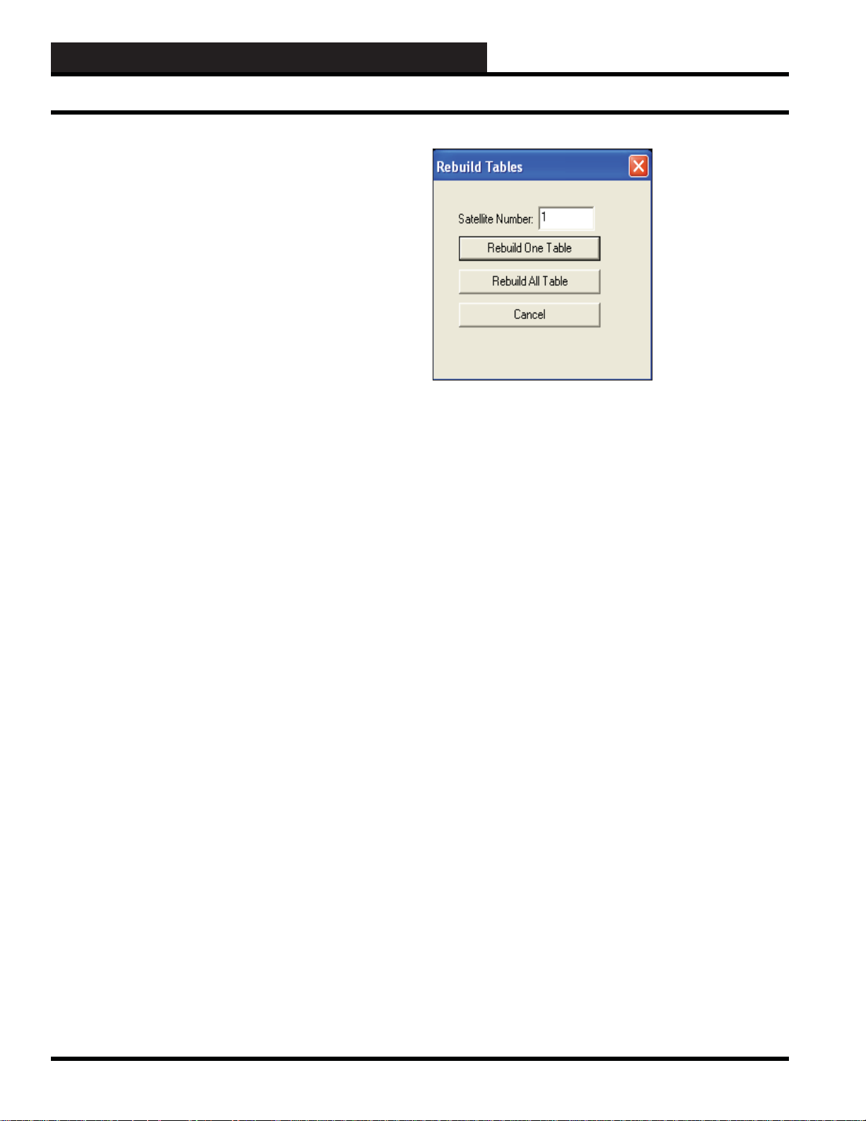
WCC3.EXE SCREEN DESCRIPTIONS
Rebuild Sa tellite Tables
REBUILD SA TELLITE T ABLES
The data pattern tables for the satellite controllers need to be
rebuilt whenever any of the following events occur:
1. A new WCC III system is installed.
2. New software is installed in the MCD or the satellite
controller.
3. New hardware is installed in the system (i.e. new
satellite controllers, new MCOMM communication
board in the MCD, etc.).
For a new system, or for new satellite controllers installed
in an existing system, the tables should be (re)built before the
programming data is entered.
Before a value is displayed on the screen, the system checks to
see where the decimal point should go. The pattern is called the
“Data Pattern.” In the WCC III system, there are four data patterns
allowed. They are “x,xxx”, “xxx.x”, “xx.xx”, and “x.xxx.” (The
x’s are used to denote numeric values and are not to be taken
literally.) Additionally, rebuilding the data tables insures that the
proper units of measure, ON/OFF, and alarm messages will be
displayed with its associated number.
After the data tables are rebuilt, the data tables will be saved on
the hard disk.
Rebuild Satellite Unit/Pa ttern Table:
T o rebuild one or more satellite tables, from the Main Menu Tool
Bar select <Action>, <Rebuild Satellite Unit/Pattern Table>.
The following window will appear:
Satellite Number:
This entry allows you to designate the number of the satellite
controller which will have its table rebuilt.
Enter the satellite number and then select the option to
One Table>. To rebuild all tables, type a zero in the satellite
number fi eld and select <Rebuild All T ables>.
Rebuild One T able:
Select this option to rebuild the data table for only one satellite.
Rebuild All T ables:
To insure proper rebuilding of tables, we recommend that you
select this option to allow the system to rebuild data tables for all
of the satellite controllers and the Global Analog Screens.
<Rebuild
3-90
WCC III Technical Guide
Page 95

WCC3.EXE SCREEN DESCRIPTIONS
Override Screen
OVERRIDE SCREEN
OVERRIDE SCHEDULES
Starting End
ADDRESS Type/Value TIME MONTH DAY TIME MONTH DAY
W12 Off 745 2 15 845 2 15
S5 Off 745 2 15 845 2 15
GB9 On 745 2 15 845 2 15
GA15 72.5 Deg F 950 2 16 1200 2 17
GA10 30.0 Deg F 1130 3 17 2200 3 18
184K2C Schd On 900 4 11 1500 4 14
HOME for menu
This screen allows you to override addresses within the system for
programmable time periods. The allowable choices for override
type depend on the password level.
With Level 1 Password, choices are <Schd On, Schd Off>
With Level 2 Password, choices are <SchdON, SchdOff>
With Level 3 Password, choices are <ALL>
ADDRESS
This is a user entered fi eld which initiates the Override program of
the WCC III system. Addresses which may be used on this screen
are shown below:
# = Satellite address number
#An - Analog Input (n = 1 to 8)
#Pn - Analog Output (n = 1 to 8)
#KnH - Control Output (H Contact) (n = 1 to 8)
#KnC - Control Output (C contact) (n = 1 to 8)
Wn - Week Schedule (n = 1 to 128)
Sn - Optimal Start (n = 1 to 64)
GBn - Binary Global (n = 1 to 512)
GAn - Analog Global (n = 1 to 256)
#RnA - Data Register (n = 1 to 8)
#RnB - Data Register (n = 1 to 8)
#Cn - Comparator (n = 1 to 8)
#On - Binary Out (n = 1 to 16)
#Ln - Binary Input (n = 1 to 16)
Type/Value
The Type or Value of the address is entered in this position. A
binary type of address will have a type of either being ON or OFF .
An analog address will have a numerical value such as °F, PSI,
KW, % Sun, etc.
----- Starting -----
----- End -----
The Start and End portion of the program is where you enter the
Time, Month, and Day for the override to occur. The override will
erase itself from the screen after the override has been completed.
Clear Structure
Select <Clear Structure> from the Action Menu or select the
Clear Structure icon to clear the values from the screen.
NOTE: V alues entered may remain after you clear the
structure until you leave the screen and return to the Main
Menu and then open the Override Scr een again.
WCC III Technical Guide
3-91
Page 96

WCC3.EXE SCREEN DESCRIPTIONS
Holiday Schedule Screen
HOLIDAY SCHEDULE SCREEN
HOLIDAY SCHEDULE
Start End
TIME MONTH DAY TIME MONTH DAY
0000 10 26 2359 7 4
0000 11 2 2359 11 2
0000 11 9 2359 11 9
0000 11 16 2359 11 9
0000 11 23 2359 11 16
0000 11 30 2359 11 23
--- --- --- 2359 11 30
--- --- --- --- --- ---
--- --- --- --- --- ---
--- --- --- --- --- ---
--- --- --- --- --- ---
--- --- --- --- --- ---
--- --- --- --- --- ---
--- --- --- --- --- ---
--- --- --- --- --- ---
--- --- --- --- --- ---
--- --- --- --- --- ---
HOME for menu
--------Start-------- ---------End--------TIME MONTH DAY TIME MONTH DAY
Enter the Start time, month, and day that you wish to begin a
holiday. Then enter the End time, month, and day that you wish
to end the holiday. The time is in 24-hour format, the month has a
range of 1 to 12 (1 for January and 12 for December), and the day
can range from 1 to 31 (depending on the month).
There must be at least eight hours between the Start time and End
time of the Holiday. If a shorter time is needed, you will need to
set up the strategies within the Override Screen, described on page
3-91.
The Holidays may be entered up to one year in advance and may
be entered out of sequence.
Each week schedule has a location at the bottom of the screen
named HOL as shown in the Week Schedule Screen. This HOL
location becomes active on the dates listed on the Holiday Schedule
Screen.
3-92
WCC III Technical Guide
Page 97

WCC3.EXE SCREEN DESCRIPTIONS
Holiday Schedule Screen
Week Schedule Screen’s WCC III Logical Address is Wnn, where W = Week Schedule and nn = Week Schedule#
WEEK SCHEDULE 1
Description: Linux Week Schedule
Current status Night Week OFF WED 0707
On Message #: 7 Week Day Password level req’d to alter: 3
Off Message #: 8 Week Night
DAY EVENT EVENT EVENT EVENT EVENT EVENT
MON on 0800 off 1700 --- --- --- ---
TUE on 0800 off 1700 --- --- --- ---
WED on 0800 off 1700 --- --- --- --THR on 0800 off 1700 --- --- --- ---
FRI on 0800 off 1700 --- --- --- --SAT on 1000 off 1400 --- --- --- ---
SUN off 1000 off --- --- --- --HOL off 0000 --- --- --- --- ---
HOME for menu
The week schedule will obey the entries listed on the HOL line
when a holiday occurs. In this example, the week schedule will be
OFF on the dates listed as holidays on the Holiday Screen. (When
the system sees ---, it will remain in its present state until it sees the
next on or off command.)
There must be at least eight hours between the Start time and End
time of the Holiday. If a shorter time is needed, you will need to
set up the strategies within the Override Screen, described on page
3-91.
WCC III Technical Guide
The data on this screen DOES NOT erase itself after the holiday has
been completed. If you need to erase a particular holiday, simply
position the cursor over the value in the month column at the left
hand side of the screen of the holiday in question. Press
and then <Home>, holding both keys down at the same time and
then releasing them. The <Ctrl><Home> feature will clear out one
holiday at a time. To perform the
must have a level 3 access code.
NOTE: V alues entered may remain after you clear the
Holiday until you leave the screen and return to the Main Menu
and then open the Hol iday Sch edule Screen again.
<Ctrl><Home> function, you
<Ctrl>
3-93
Page 98

WCC3.EXE SCREEN DESCRIPTIONS
System Parameters Screen
SYSTEM PARAMETERS SCREEN
System Parameters Page 1
Present Time Authentication: Auto
Time Month Day Year User Name: mcd-test@wcc-controls.com
0710 1 21 9 Password: MCD@8500
System ID: Kansas City (On the Wall) System. Port Number 25
E-mail SMTP Server: mail.wcc-controls.com
Reply E-mail Address: mcd-parkville@wcc-controls.com
Alarm Type Disabled by E-mail Address Name Repeat Delay
1 0 1st MarkL@wattmaster.com Mark Lehman 0
0 2nd MarkL@wattmaster.com Mark Lehman 0 5
0 3rd MarkL@wattmaster.com Mark Lehman 0 5
2 0 1st MarkL@wattmaster.com Mark Lehman 0
0 2nd MarkL@wattmaster.com Mark Lehman 0 0
0 3rd MarkL@wattmaster.com Mark Lehman 0 0
3 0 1st 0
0 2nd 0 0
0 3rd 0 0
4 0 1st 0
0 2nd 0 0
0 3rd 0 0
5 0 1st 0
0 2nd 0 0
0 3rd 0 0
Operator: Code: View Screen Only
Time out: 120 Minutes Local print: YES
The WCC3 System Parameters Screen is used to enable, disable,
and setup E-mailing of Alarms for the WCC3 system.
Page:
The Page fi eld at the very top of the WCC3 System Parameters
Screen refers to the fact that there can be up to 4 separate pages for
the setup of various E-mail addresses that then can be fi lled out, so
that up to 12 separate E-mail Addresses per Alarm type can send
out Alarm E-mails. These Alarm Call-out E-mails are based upon
“Alarm T ype” 1 through 5 only . Alarm types 6, 7 and 8 do not, and
cannot, cause an Alarm Call-out E-mail to be sent out.
All of the programmed setup information for the “Present time”,
“Authentication:”, “User Name:”, “System ID:”, “Password:”.
“E-mail SMTP Server:”, “Reply E-mail Address:”, “Time out:”,
and “Local Print:” fi elds do not change with the Page toggle
function.
3-94
Present Time
Time Month Day Y ear:
Specifi es the current time and date. The time is in 24-hour
format, the month has a range of 1 to 12 (1 for January and 12 for
December), and the day can range from 1 to 31 (depending on the
current month).
User Name: Password:
For e-mail servers that require authentication, the username fi eld
needs to have a valid user name. The password fi eld needs to have
a valid password that matches with the User Name. Both of these
fi elds’ data comes from your Internet Service Provider or from
your IT Personnel.
WCC III Technical Guide
Page 99

WCC3.EXE SCREEN DESCRIPTIONS
System Parameters Screen
The User Name can be up to 30 characters (control codes, ALT
codes, and the double quote character are not allowed). The
password can be up to 20 characters (control codes, ALT codes,
and the double quote character are not allowed). The User Name
and Password are the ones set up for the Backtask program’s e-mail
account. Both the user name and password are case-sensitive.
Authentication:
For e-mail servers that require authentication, this fi eld should
be set to Auto, Login or Plain. For e-mail servers that do not
require authentication, this fi eld should be set to “No.” - See
your Internet provider and/or IT personnel for this setting.
E-mail authentication from the WCC3 system is the effort to
equip E-mail messages of the WCC3 e-mail transport system
with enough verifi able information, so that the End User
recipient’s E-mail server can recognize the nature of each
incoming message from the WCC III - MCD email’s SMTP
automatically without rejecting it as SPAM. WattMaster
Controls, Inc. supports 4 basic types of E-mail authentication—
AUTO, PLAIN, LOGIN, and CRAM-MD5.
AUTO: In the WCC3 system, the selection for authentication
“AUTO” applies to The Password Authentication Protocol
(capitalized) and is sometimes abbreviated PAP. PAP is a simple
password authentication protocol that is used to authenticate a user
to a network access server used for example by internet service
providers. PAP is used by Point to Point Protocol to validate users
before allowing them access to server resources. Almost all network
operating system remote E-mail servers support PAP. It requires
that you have both a legitimate “User Name” and “Password”.
PLAIN: In the WCC3 system, the selection for authentication
“PLAIN” applies to unencrypted “Plain” text that is sent to and
from the E-mail SMTP server. It is most commonly associated
with a POP3 type E-mail server.
The Post Offi ce Protocol (POP) is an application-layer Internet
standard protocol used by E-mail user accounts to send and
retrieve e-mail from a remote server over a TCP/IP connection.
POP and IMAP (Internet Message Access Protocol) are the two
most prevalent Internet standard protocols for e-mail retrieval.
Virtually all modern e-mail clients and servers support both. The
POP protocol has been developed through several versions with
version 3 (POP3) being the current standard.
LOGIN: Login Authentication is a process closely related to
identifi cation. In online E-mail environments where “login”
authentication is required, the username identifi es the user, while
the password authenticates that the user is whom he or she claims
to be. Typically, the “Login” authentication is used on E-mail
servers with SSL type E-mail protocols.
Secure Sockets Layer (SSL), are cryptographic protocols that
provide a level of security for secure communications over
networks such as the Internet.
CRAM-MD: In CRAM-MD5 authentication, the server fi rst
sends a challenge string to the client. The client responds with a
username followed by a space character and then a 16-byte digest
in hexadecimal notation. The digest is the output of HMAC-MD5
with the user’s password as the secret key and the server’s original
challenge as the message. The server also calculates its own digest
with its notion of the user’s password, and if the client’ s digest and
the server’s digest match then authentication is successful.
This provides three important types of security. First, others cannot
duplicate the hash without knowing the password. This provides
authentication. Second, others cannot replay the hash—it is
dependent on the unpredictable challenge. This is variously called
freshness or replay prevention. Third, observers do not learn the
password. This is called secrecy . The two important features of this
protocol that provide these three security benefi ts are the one-way
hash and the fresh random challenge.
System ID:
The system ID fi eld on the WCC3 System Parameters Screen
is used to identify the actual physical location of the WCC3
system. This System ID “Name” will be on all of the E-mails
that this specifi c WCC III - MCD will send out, in the center of
the Main Screen of the WCC3.exe program, and on the Energy
Consumption Table. This fi eld on the WCC3 System Parameters
Screen is limited to 50 total characters (control codes, ALT codes,
and the double quote character are not allowed) for the System
ID.E-Mail SMTP Server:
WCC III Technical Guide
3-95
Page 100

WCC3.EXE SCREEN DESCRIPTIONS
System Parameters Screen
E-Mail SMTP Server:
(SMTP) Simple Mail Transfer Protocol is an Internet standard for
electronic mail (e-mail) transmission across Internet Protocol (IP)
networks. This fi eld on the WCC3 System Parameters screen is
limited to 52 total characters for the E-mail address.
W attMaster Controls can and will usually provide an initial E-Mail
SMTP server for the initial setup of the WCC III - MCD when it
is fi rst installed. This SMTP Server that is provided by WattMaster
Controls is not guaranteed to last for the life of the WCC3 system.
At some point in the future, there may also be a service fee
associated with maintaining this SMTP server from WattMaster
Controls.
Port Number
The WCC3.exe program opens a two-way , secure communications
port that then allows for communication between WCC III – MCD
and the WCC3.exe program that is running on the WCC III front
end computer. This IP Address connection is done on a higher
address port number than normal (WCC III connection is port
number 39289) to help reduce the risk of computer hacking.
Port Number 25 should always be used on the WCC3 system,
but in rare instances other port addresses can be used to improve
security on the WCC III – MCD. This generally requires advanced
IT support for implementation.
Port Number “25” is the usual TCP port for common SMTP
operation.
Disabled by
The Disabled by fi eld is used to enable or disable the specifi c alarm
type. (Remember that there can be 4 pages of E-mail addresses.)
An “ON” or “1” disables the E-mailing of the Alarm type Callout
function per E-mail address. An “OFF” or “0” enables the E-mailing
of the Alarm type Call-out function per E-mail address.
This “Disabled by” fi eld can be programmed with the following:
0 (OFF), 1(ON), WXXX (Week Schedules), SXXX (Optimal
Starts), GBXXX (Global Binaries), new day, new hour, new min,
GCXXX, GHXXX, GLXXX (T enant Override groups), LOCSET
(Local Set Mode), TEST (TEST Mode), / = / / / / (For Null value).
Just remember that the / / / / is a Null function that is neither “ON”
or “OFF”, but is generally treated as “OFF” condition but not
always.
Email Address
The E-mail Address fi eld on the WCC3 System Parameters
Screen is the E-mail address that you want send the specifi c
WCC3 Alarm E-mail that is based on Alarm type 1 to 5. There
can be up to 12 E-mail address per alarm type. This E-mail
Address fi eld on the WCC3 System Parameters Screen is
limited to 50 total characters for the E-mail address.
1st, 2nd, 3rd Email Address
The “1st” E-mail Address is the primary or the fi rst E-mail
address that the WCC3 alarm type (1 to 5) will send an E-mail
alarm to.
Reply E-mail Address:
Some E-mail SMTP servers require a reply E-mail address during
the Authentication process.
The End User on the WCC3 system with internet access should
have an E-mail address that usually is provided with the static
internet address or static Host name that comes from the internet
service provider. This fi eld on the WCC3 System Parameters
Screen is limited to 52 total characters for the E-mail address.
Alarm Type:
There are 5 Alarm types that can be programmed to send out an
Alarm E-mail to specifi c E-mail address.
The “2nd” E-mail Address is the secondary or second E-mail
address that the WCC3 alarm type (1 to 5) will send an E-mail
to after sending the fi rst E-mail of the alarm type.
The “3rd” E-mail Address is the tertiary or third E-mail
address that the WCC3 alarm type (1 to 5) will send an E-mail
to after sending the second E-mail of the alarm type.
NOTE: On only the fi rst 3 alarm class 1 E-mail addresses on
page 1 of the System Parameters E-mail addresses will receive
a automated Satellite Off System (SOS) E-mail message that is
sent out to these E-mail addresses when a Satellite controller or
multiple Satellite Controllers go off line (SOS). See the Alarms
section of this manual for more information on Satellite alarms.
3-96
WCC III Technical Guide
 Loading...