

Page 1

4. SCUSCR.EXE Screens
WCC III
4. SCUSCR.EXE Screens
Page 2

T ABLE OF CONTENTS
SECTION 4:
SCUSCR.EXE SCREENS
How to Start or Run the SCUSCR.exe
Program....................................................... 4-1
Controller Overview ....................................4-3
SCUSCR.EXE Screens Index.......................4-5
WCC VAV BOX III Sequence of Operation
(SS5010) ......................................................4-6
Modes of Operation ....................................4-8
Tenant Override Logs ...............................4-14
Series Fan Powered Pressure Dependent
Status & Setpoint Screens ....................... 4-58
Series Fan Powered Pressure Independent
Status & Setpoint Screens ....................... 4-60
Single Duct Changeover Pressure Dependent
Status & Setpoint Screens ....................... 4-62
Single Duct Changeover Pressure Independent
Status & Setpoint Screens ...................... 4-64
Single Duct Reheat Pressure Dependent
Status & Setpoint Screens ....................... 4-66
Single Duct Reheat Pressure Independent
Status & Setpoint Screens ....................... 4-68
Alarm Detection and Reporting ................4-15
WCC III VAV BOX III Trend Logging ..........4-15
Force Modes or Overrides ........................4-16
SCUSCR.EXE SCREENS ............................4-17
SAT 3D Addressing to TUC Control
Points ........................................................4-18
Single Duct Cooling-Only Screens............4-30
Single Duct Cooling-Only Screens –
Pressure Independent ..............................4-37
Parallel Fan Powered Pressure
Dependent Screens ..................................4-44
Parallel an Powered Pressure
Independent Screens ................................ 4-51
Page 3
4. SCUSCR.EXE SCREENS
Running the SCUSCR Program
SECTION 4:
SCUSCR.EXE SCREENS
__________________________________________
How to Start or Run the SCUSCR.exe
Program (SS5026)
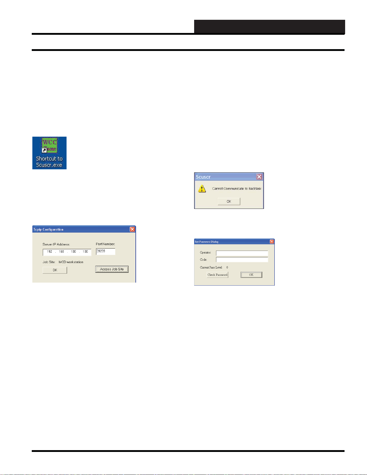
The SCUSCR.exe shortcut icon should have
been installed on your WCC III front end
computer desktop with the WCC III Installation
Software CD. The WCC III Installation Software
CD is WattMaster Controls Part # DM1WC01101X.
To start the SCUSCR.exe program, double-click the left mouse
button on the Shortcut Icon found on the Windows desktop. After
a short period of time, dependent upon the CPU speed of your
Windows based computer and the speed of your IP connection to
the internet, the WCC III T ype Connection Dialog Box will appear.
on the WCC III Front end computer. This IP Address connection
is done on a higher address port number than normal (WCC
III connection is port number 39289) to help reduce the risk of
computer hacking.
Using your mouse, left-click on the <Access Job Site> button.
The Remote Access Dialog Window will appear.
By selecting <OK>, the SCUSCR.exe program will now start to
connect to the selected WCC III – MCD via this selected IP address
connection. It should bring up the WCC III SCUSCR Set Password
Dialog screen within a new window. If the IP address connection
fails to connect to the WCC III – MCD, then another small dialog
box window will appear. This is the Cannot Communicate to
Backtask Dialog Box.
Once you click <OK>, you will exit the SCUSCR.exe program.
You will have to fi gure out why you cannot connect to the WCC
III – MCD via the IP address connection.
Server IP Address:
This is the static IP address of the WCC III – MCD. An IP Address
is like a phone number on the world wide web. The IP address for
the WCC III – MCD must be Static (does not change) as opposed
to Dynamic (constantly changing). This static IP address must be
provided by your internet service provider. (A static IP address
is the preferred IP connection method for the WCC III system to
function.) If you actually know the static IP address of the WCC
III – MCD that you wish to connect to, please enter it here in the
Server IP Address fi eld, or better yet, continue to the Remote Access
Dialog Window by selecting the <Access J ob Site> button.
You can use a Dynamic IP Address with the WCC III – MCD,
but you must then have what is called a static “Host Name”. This
static “Host name” must then be provided by your internet service
provider and is limited to 58 total characters.
Port Number:
The SCUSCR.exe program opens a two-way, secure
communications port that then allows for communication between
the WCC III – MCD and the SCUSCR.exe program that is running
WCC III Technical Guide
In the Set Password Dialog Screen enter an “Operator:”
identifi cation and a “Code:” or password equal to at least a pass
level 0 that has been previously set up on the WCCIII System
Parameter – Operator Code Screen. (See the Operator Code
Screen of the System Parameter Screen in Section 3 for information
on setting up Operator Codes.) Click <Check Password>. If the
“Current Pass Level:” stays at 0 or higher (1, 2, or 3), then click
<OK>. By selecting <OK>, the SCUSCR.exe program will now
start to connect to the selected WCC III – MCD via this selected
IP address connection. It should bring up the SCUSCR - Demo
Screen within a new window. If the “Current Pass Level:” changes
to –1 then you do not have access to the WCCIII – MCD. If you
do not have access to the WCCIII – MCD and you click <OK>
then this connection to the SCUSCR.exe program is not an actual
IP connection, but rather a “dummy” SCUSCR - demo screen
window with no values.
4-1
Page 4
4. SCUSCR.EXE SCREENS
Running the SCUSCR Program
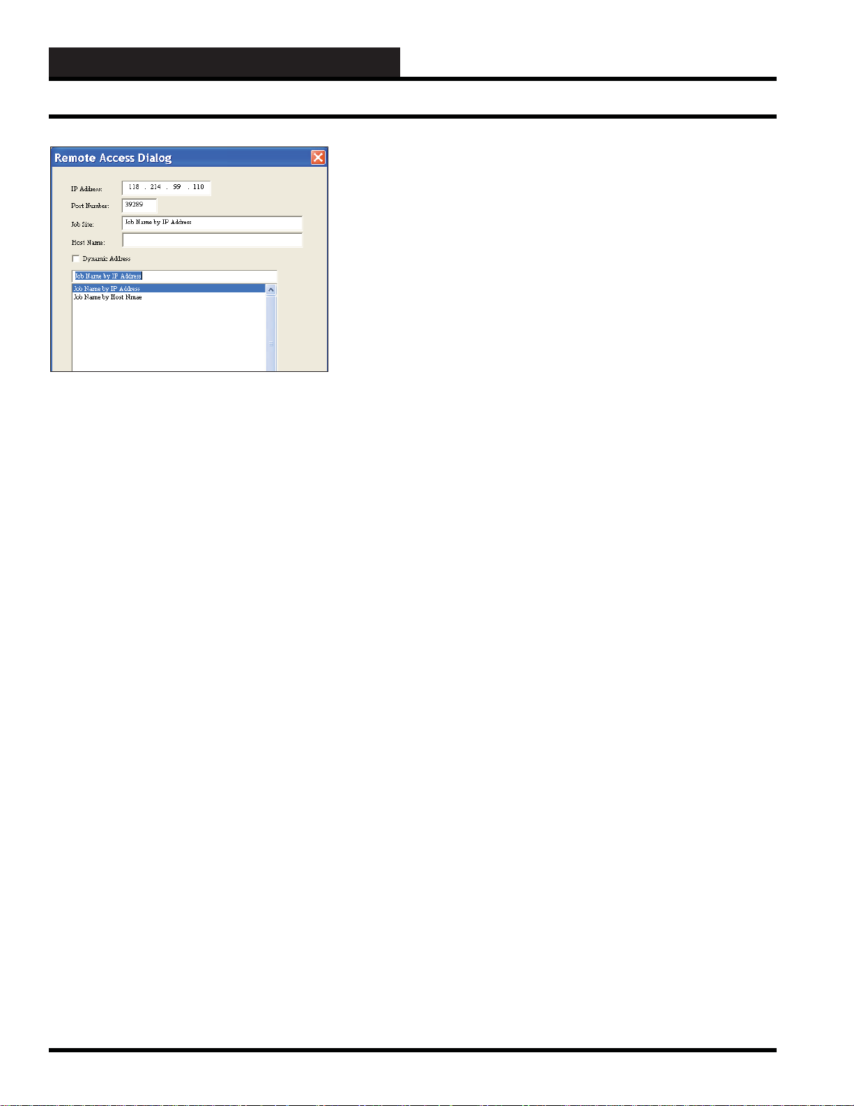
The Remote Access Dialog Box will allow you to enter multiple
WCC III – MCD IP addresses based upon “Job Site” names. This
is done by typing in the name of the jobsite you wish to call your
system.
First you must select a “BLANK” line in the bottom box area
with your left mouse button. (This line will then be highlighted
in “Blue”.) You must then enter a Job Site name in the “Job Site”
fi eld, along with the static IP address and Port number (39289) for
the WCC III – MCD that you wish to connect to with the SCUSCR.
exe program.
If you are using a static “Host Name” instead of a static IP address,
please make sure that the Dynamic Address check box has been
selected, along with the static “Host Name” in the space provided.
As mentioned previously, you must get this static “Host Name”
from your internet service provider, and it is limited to 58 characters
total.
Please note that this “Job Site” name will also be the name of a
subdirectory that will automatically be created in the Local disk
C:\ProgramFiles\WCCIII\SCUSCR subdirectory on the WCC III
Front end computer. The Remote Access Dialog Box also creates
a JobSite.dat data fi le in the C:\ProgramFiles\WCCIII\SCUSCR
subdirectory. This data fi le is not a viewable type of fi le. The
JobSite.dat fi le can be copied and then can be used on other WCC
III front end computers. This reused JobSite.dat will then recreate
the needed “Job Site” subdirectories on the other WCC III front
end computers upon the reselection of the Job Site IP address.
In an already fi lled out Remote Access Dialog Box, you can simply
select from the list of previously entered Job Sites that are displayed
in the bottom box fi eld. Then left-click <OK>. This will take you
back to the Connection Dialog Box that was fi rst displayed. This
Connection Dialog Box now should have the desired IP address in
the Server IP Address location fi eld and the port number (39289)
in the Port Number location fi eld for the WCC III – MCD that you
wish to connect to with the SCUSCR.exe program.
IP Address:
This is the static IP address where the WCC III – MCD is located.
An IP Address is like a phone number on the world wide web.
The IP address for the WCC III – MCD must be static (does not
change) as opposed to Dynamic (constantly changing). This static
IP Address must be provided by your internet service provider.
(A static IP address is the preferred IP connection method for the
WCC III system to function.)
Port Number:
The SCUSCR.exe program opens a two-way, secure
communications port that then allows for communication between
the WCC III – MCD and the SCUSCR.exe program that is running
on the WCC III front end computer. This IP Address connection
is done on a higher address port number than normal (WCC
III connection is port number 39289) to help reduce the risk of
computer hacking.
Job Site:
This is the name of the jobsite you wish to call your system. Please
note that this name will also be the name of a subdirectory that
will automatically be created in the Local disk C:\ProgramFiles\
WCCIII\SCUSCR subdirectory.
Host Name:
You can use a Dynamic IP Address with the WCC III – MCD,
but you must then have what is called a static “Host Name”. This
static “Host name” must then be provided by your internet service
provider and is limited to 58 total characters.
When you have fi lled out all necessary fi elds, left-click <OK>.
This will take you back to the Connection Dialog Box that was
fi rst displayed. This Connection Dialog Box now should have the
desired IP address in the Server IP Address location fi eld and the
port number (39289) in the Port Number location fi eld for the
WCC III – MCD that you wish to connect to with the SCUSCR.
exe program.
Left-click
was fi rst displayed. The Connection Dialog Box will have the
same IP address as listed originally before in the Server IP Address
location fi eld and the port number (39289) in the Port Number
location fi eld.
Left-click <Print> to send all of this data in this Remote Access
Dialog Box to your Windows system default printer on the WCC
III front end computer. This print function is provided to give you
a hard paper backup copy of these IP address for the various WCC
III – MCD that you may have. This print function also creates a
Printscreen.dat data fi le in the C:\ProgramFiles\WCCIII\SCUSCR
subdirectory. This data fi le is not a viewable type of fi le.
<Cancel> to return to the Connection Dialog Box that
4-2
WCC III Technical Guide
Page 5

4. SCUSCR.EXE SCREENS
Overview of Controllers
Controller Overview
WattMaster Controls, Inc. produces a line of application-specifi c
controllers that perform a multitude of various specifi c dedicated
functions. These dedicated controllers have a WCC user’s
interface that is referred to as the SCUSCR.exe program. With
this SCUSCR.exe program, you can view temperatures, setpoints,
schedules, actuator position, global control commands, etc. and
conversely with this same SCUSCR.exe program, you would
be able to confi gure and modify the setpoints, schedules, global
control commands, etc. of any of these various specifi c dedicated
controllers. The three basic type controllers are listed below along
with the two types of WCC III types of interfaces:
TUC2R (OE320) - Used mainly for VVT or VAVBOX
type of applications
Two relays for direct control of the damper actuator with an actuator
output connector with damper position input, a room temperature
sensor input with override and adjust options, and an Expansion
board connector for optional AUX fan and AUX Heating, Hot
water/Chilled water valve connections.
You must consult the specifi c application for the wiring, setup, and
programming confi guration for the exact software application you
are using.
TUC5R (OE330) and TUC5R+ (OE331) - Used mainly
for CV and Heat Pump applications
One Relay output for Fan ON/OFF control and 4 relay outputs that
are usually confi gurable for 1 to 2 stages of heating and/or cooling.
Room temperature sensor input/ with override and adjust options,
various sensor connections for measuring, supply air, return air,
and outdoor air temperatures. Analog outputs for VFD control.
The TUC5R has an optional further enhancement called TUC5R+.
The TUC5R+ has an additional couple of analog inputs, and extra
analog output, and an I2C expansion connection.
RTU-17 (OE310) - Used for Main unit VVT control,
some complex CV, General Purpose Input Output
ON/OFF controller, and dedicated AHU control
applications
One Relay output for Fan ON/OFF control and 4 relay outputs
that are usually confi gurable for 1 to 2 stages of heating and/or
cooling. Two relays are for direct control of the damper actuator
with a damper position input, a Room Temperature sensor input
with override and adjust options, various sensor connections for
measuring, supply air, return air, and outdoor air temperatures.
Analog output for VFD control.
You must consult the specifi c application for the wiring, setup, and
programming confi guration for the exact software application you
are using.
SAT 3C (OE455) - Used to interf ace the RTU-17
controller and some of the more complex TUC5R(+)
controller software applications to the WCC III
system
The SAT 3C occupies 8 SAT III addresses on the Satellite
controller loop and is used as a data exchange device between the
RTU-17 and/or TUC5R(+) data control points and the main WCC
III data structures.
SAT 3D (OE455) - Used to interf ace the TUC2R
controller and some of the more complex TUC5R(+)
controller software applications to the WCC III
system
The SAT 3D occupies 4 SAT III addresses on the Satellite
controller loop and is used as a data exchange device between the
TUC2R and/or TUC5R(+) data control points and the main WCC
III data structures.
SAT 3F (OE456) - Used to interf ace the VAV/Zone
Actuator package with the more complex V AV/Zone
controller application software to the WCC III system
You must consult the specifi c application for the wiring, setup, and
programming confi guration for the exact software application you
are using.
WCC III Technical Guide
The SAT 3F occupies 4 SAT III addresses on the Satellite
controller loop and is used as a data exchange device between the
VAV/Zone controller actuator package data control points and the
main WCC III data structures.
4-3
Page 6

4. SCUSCR.EXE SCREENS
Variable Air V olume, Heat Pump, & Constant V olume Overview
V AV Ov erview
Variable Air volume (VAV) is a technique for controlling the
capacity of a heating, ventilating, and/or air-conditioning (HVAC)
system. The simplest VAV system incorporates one supply duct
that, when in cooling mode, distributes approximately 55°F (13°C)
supply air. Because the supply air temperature, in this simplest of
VAV systems, is constant, the airfl ow rate must vary to meet the
rising and falling heat gains or losses within the thermal zone
served.
There are two primary advantages to VAV systems. The fan
capacity control, especially with modern electronic variable
speed drives, reduces the energy consumed by fans which can
be a substantial part of the total cooling energy requirements of
a building. Dehumidifi cation demands are greater with a VAV
system than with a constant volume system which modulates the
discharge air temperature to attain part load cooling capacity.
The air blower’s airfl ow rate must be variable. For a single VAV air
handler that serves multiple thermal zones, the airfl ow rate to each
zone must be varied as well.
A VAV terminal unit controller, often called a VAV BOX, is
the zone-level airfl ow control device. It is basically a quality,
calibrated air damper with an electronically controlled actuator.
The VAV terminal unit is connected to a local SAT 3d controller
which then connects to a central control system (WCC III - MCD).
Historically, pneumatic control was commonplace, but electronic
direct digital contr ol systems are popular especially for mid-to-large
size applications. Hybrid control, for example, having pneumatic
actuators with digital data collection, is popular as well.
Control of the system’s main fan capacity is critical in VAV
systems. Without proper and rapid airfl ow rate control, the
system’s ductwork, or its sealing, can easily be damaged by over
pressurization. This system airfl ow control is usually done with a
SAT III controller with the feedback from the zones in a global
format.
While invented earlier, TempMaster (WattMaster) Corporation of
Kansas City, Missouri is generally credited with perfecting early
VAV technology. The VAV BOX hardware and software (Actuator,
TUC Controller, Temperature sensor, differential pressure sensor,
and proprietary software) is the heart of the technology.
Heat Pump Overview
The most common type of heat pump is an “air-source” system.
“Split” air-source systems have an outdoor unit which includes
a compressor, outdoor coil, fan, and reversing valve. The unit is
connected with refrigerant-fi lled tubing to an indoor component.
The indoor unit contains a fan, indoor coil, and a supplemental
resistance heating element. “Package” systems combine both
components in a single unit that’s typically placed on the roof.
Depending on whether the heat pump is in a cooling or heating
mode, the refrigerant moving through the system makes the indoor
coils either hot or cold. A blower draws room air in through a fi lter
and pulls it across the indoor coil. An optional electric-resistance
heating element can kick on when needed to supplement the heat.
As the air passes by the coils, it either gathers or gives off heat
depending on whether the coils are hot or cold. Warm or cool air
travels through ductwork and registers into the building’s rooms.
Heat pumps give off less heat at one time than do conventional
gas furnaces. This means that they offer a mellower type of heat,
do not turn off and on with the same frequency as a gas furnace,
and therefore circulate more air throughout the building. They are
controlled by the same type of basic controls used for forced-air
systems. On really cold days, a heat pump must work especially
hard to collect heat. That’s when the supplemental heater switches
on.
Constant V olume Overview
Constant Volume (CV) is a type of heating, ventilating, and airconditioning (HVAC) system. In a very basic simple CV system,
the supply air fl ow rate is constant, but the supply air temperature
is varied to meet the thermal loads of the space.
Most CV systems are small and serve a single thermal zone.
However, variations such as CV with reheat, CV multizone, and
CV primary-secondary systems can serve multiple zones and
larger buildings.
In mid to large size buildings, new central CV systems are not very
common. Due to fan energy savings potential, variable air volume
(VAV) systems are more common. However, in small buildings
and residences, CAV systems are often the system of choice due to
simplicity, low cost, and reliability. Such small CAV systems often
have on/off control rather than supply air temperature modulation
to vary their heating or cooling capacities.
There are two types of CV systems that are commonly in use to
modify the supply air temperature—the terminal reheat system and
the mixed air system.
The terminal reheat system cools the air in the air handling unit
down to the lowest possible needed temperature within its zone of
spaces. This supplies a comfortable quality to the space but wastes
energy.
The mixed air system has two air streams, typically one for the
coldest and one for the hottest needed air temperature in the zone.
The two air streams are strategically combined to offset the space’s
load. The mixed air system option is not as profi cient at controlling
the humidity, yet it does do well at controlling the temperature.
4-4
WCC III Technical Guide
Page 7

4. SCUSCR.EXE SCREENS
SCUSCR.EXE Screens Index
WCC V AV BOX III (WattMaster Software SS5010)
Sequence of Operation 4-6
Figure 4-1: VAV BOX Status Screen 4-17
Figure 4-2: VAV BOX Setpoint Screen 4-22
Figure 4-3: TempMaster Corporation V AV BOX CFM Sizing Chart 4-24
Figure 4-4: VAV BOX Globals Screen 4-25
Figure 4-5: VAV BOX Mode of Operation Screen 4-27
WCC V AV BOX II (WattMaster Software SS5001)
Sequence of Operation 4-28
Figure 4-6: Single Duct Cooling Only - Pressure Dependent Status Screen 4-30
Figure 4-7: Single Duct Cooling Only - Pressure Dependent Setpoint Screen 4-32
Figure 4-8: Single Duct Cooling Only - Pressure Dependent Globals Screen 4-34
Figure 4-9: Single Duct Cooling Only - Pressure Dependent Mode of Operation Screen 4-36
Figure 4-10: Single Duct Cooling Only - Pressure Independent Status Screen 4-37
Figure 4-11: Single Duct Cooling Only - Pressure Independent Setpoint Screen 4-39
Figure 4-12: Single Duct Cooling Only - Pressure Independent Globals Screen 4-41
Figure 4-13: Single Duct Cooling Only - Pressure Independent Setup Screen 4-43
Figure 4-14: Parallel Fan Powered - Pressure Dependent Status Screen 4-44
Figure 4-15: Parallel Fan Powered - Pressure Dependent Setpoint Screen 4-46
Figure 4-16: Parallel Fan Powered - Pressure Dependent Globals Screen 4-48
Figure 4-17: Parallel Fan Powered - Pressure Dependent Mode of Operation Screen 4-50
Figure 4-18: Parallel Fan Powered - Pressure Independent Status Screen 4-51
Figure 4-19: Parallel Fan Powered - Pressure Independent Setpoint Screen 4-53
Figure 4-20: Parallel Fan Powered - Pressure Independent Globals Screen 4-55
Figure 4-21: Parallel Fan Powered - Pressure Independent Mode of Operation Screen 4-57
Figure 4-22: Series Fan Powered - Pressure Dependent Status Screen 4-58
Figure 4-23: Series Fan Powered - Pressure Dependent Setpoint Screen 4-58
Figure 4-24: Series Fan Powered - Pressure Dependent Globals Screen 4-59
Figure 4-25: Series Fan Powered - Pressure Dependent Setup Screen 4-59
Figure 4-26: Series Fan Powered - Pressure Independent Status Screen 4-60
Figure 4-27: Series Fan Powered - Pressure Independent Setpoint Screen 4-60
Figure 4-28: Series Fan Powered - Pressure Independent Globals Screen 4-61
Figure 4-29: Series Fan Powered - Pressure Independent Setup Screen 4-61
Figure 4-30: Single Duct Changeover - Pressure Dependent Status Screen 4-62
Figure 4-31: Single Duct Changeover - Pressure Dependent Setpoint Screen 4-62
Figure 4-32: Single Duct Changeover - Pressure Dependent Globals Screen 4-63
Figure 4-33: Single Duct Changeover - Pressure Dependent Setup Screen 4-63
Figure 4-34: Single Duct Changeover - Pressure Independent Status Screen 4-64
Figure 4-35: Single Duct Changeover - Pressure Independent Setpoint Screen 4-64
Figure 4-36: Single Duct Changeover - Pressure Independent Globals Screen 4-65
Figure 4-37: Single Duct Changeover - Pressure Independent Setup Screen 4-65
Figure 4-38: Single Duct Reheat - Pressure Dependent Status Screen 4-66
Figure 4-39: Single Duct Reheat - Pressure Dependent Setpoint Screen 4-66
Figure 4-40: Single Duct Reheat - Pressure Dependent Globals Screen 4-67
Figure 4-41: Single Duct Reheat - Pressure Dependent Setup Screen 4-67
Figure 4-42: Single Duct Reheat - Pressure Independent Status Screen 4-68
Figure 4-43: Single Duct Reheat - Pressure Independent Setpoint Screen 4-68
Figure 4-44: Single Duct Reheat - Pressure Independent Globals Screen 4-69
Figure 4-45: Single Duct Reheat - Pressure Independent Setup Screen 4-69
WCC III Technical Guide
4-5
Page 8
4. SCUSCR.EXE SCREENS
WCC III V A V BOX III Sequence of Operations
WCC V A V BOX III Sequence of
Operation
(WattMaster Software Number SS5010)
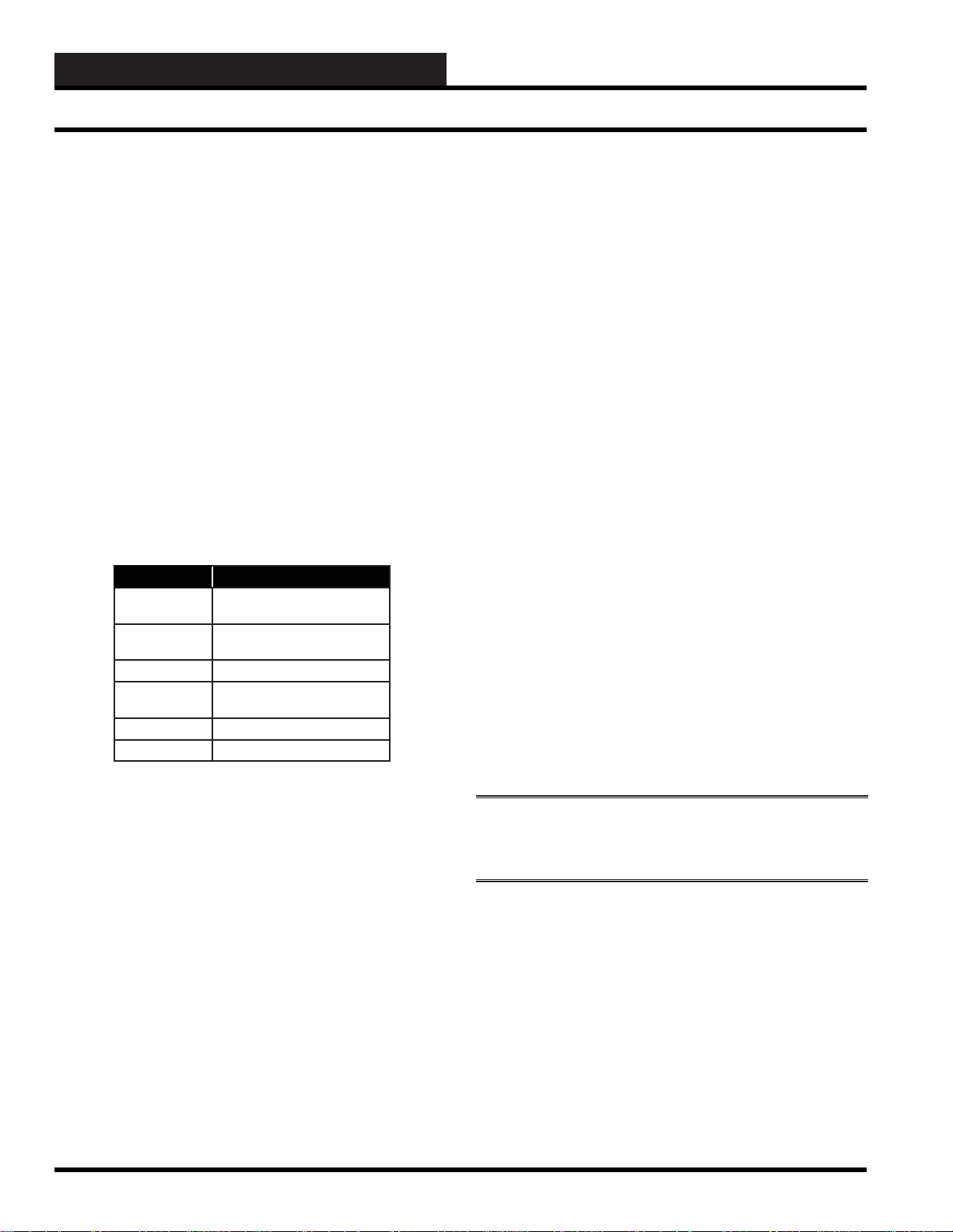
Initialization
On initial power-up of the VAV BOX TUC-2R controller, the
SCAN LED is extinguished for a few seconds and then the VAV
BOX TUC-2R controller “fl ashes” its address switch setting. If
the address switch were set to 7, you would see 7 fl ashes. After
the address is fi nished, the LED will extinguish for another 5
seconds. At the conclusion of this 5 second delay, the LED will
begin a continuous fl ashing while the Damper Feedback limits
are calibrated. If the Damper is driving open, the LED will blink
slowly. If the Damper is driving closed, the LED will blink fast.
When the calibration is completed, the normal diagnostic fl ashes
will commence. These troubleshooting diagnostic LED fl ashes are
listed below in Table 4-1.
No. of Blinks Description
1 Normal Operation
No Alarm Conditions Exist
2 Push Button Override or
Group Override is Active
4 Bad Airfl ow Sensor
5 Bad or Missing Space
Sensor
6 Damper Failure
7 Damper Feedback Failure
Table 4-1: LED Blink Codes
V AVBOX Confi guration & Setup
General
There are several options that are available to confi gure the WCC
VAVBOX III controller for the appropriate equipment that it is
installed on. All of these options can be set from the “four main
screens” that are viewable from the SCUSCR.exe program. You
can toggle through these four screens selections by pressing <Ctrl>
+ <►> (right arrow), which means next page or <Ctrl> + <◄>
(left arrow), which means previous page.
VAV Box Control Method
Set this confi guration item for the type of box the VAVBOX
controller is used on. The options available are:
0 = Cooling Only Box (with Reheat if required)
1 = Heating/Cooling Changeover Box
2 = Series Fan Powered Box with Reheat
3 = Parallel Fan Powered Box with Reheat
Damper Operating Mode
Set the direction of rotation that the damper moves when driving
towards its full open position. The following options available
are:
0 = Direct Acting (Clockwise to Open Damper)
1 = Reverse Acting (Counterclockwise to Open Damper)
Pressure Independent Boxes - Airfl ow @ 1” W.C.
If this is a pressure independent box, this option allows you to
calibrate the box CFM correctly using the VAV box manufacturer’s
“K” factor. You must enter the correct “K” (CFM) factor for the
inlet diameter of the box you are confi guring.
NOTE: VAVBOX TUC-2R controllers will
automatically operate as pressure independent if the box
size constant is greater than 0 CFM.
There are quite a few confi guration selections available which
can be then used to tailor the WCC III VAV BOX III software
(WM Software # SS5010) operation to match the exact type of
mechanical VAV box equipment that this VAV BOX TUC-2R
controller is installed on. These setpoint and confi guration items
are programmed using a Windows-based personal computer that
has the WCC III computer front-end software installed.
The SCUSCR.exe is the program that is used to view, modify, or
program these selections. There are four main screens that are
used for the viewing, programming, and setup of the WCC III VAV
BOX III software that is installed on the TUC-2R controller.
4-6
Expansion Relays - Steps of Reheat
If the VAV box has reheat that is supplied by an electric coil, then
this option must be set for the number of electric heating stages on
the VAV box. If the VAV box has hot water heat with a 2 position
hot water valve, set the number of stages to “1”. For hot water heat
with a proportional hot water valve, set to “0”.
Options available are:
0 = No Staging
1 = 1 Stage of Reheat
2 = 2 Stages of Reheat
3 = 3 Stages of Reheat
WCC III Technical Guide
Page 9

4. SCUSCR.EXE SCREENS
WCC III V A V BOX III Scheduling
Proportional Heating Signal
If the VAV box has hot water reheat using a proportional hot water
valve, it is a 0-10 VDC Voltage Signal.
Allow V AV Box Heat with AHU Heat
If the VAV box that you are using has reheat, confi guring this
setting will allow the VAV box heat to operate at the same time as
the HVAC unit heat.
This is the actual statement on the screen “Allow box heat to
Remain On in the HVAC mode at the same time as the HVAC
unit”
Options available are:
0 = No
1 = Yes
Main Fan Status
If the VAVBOX TUC-2R controller is installed on a non-fan
powered box that has reheat, set this option to “1” in order to
enable box reheat only when the HVAC unit fan is running. A full
description of how this setting affects the various box types in the
occupied and unoccupied modes is contained under the “Mode
Sequence” heading that follows later in this manual. This is the
actual statement on the screen “This Box Needs the Main Fan
Status.”
Options available are:
0 = No - Heat can operate without fan
1 = Yes - Heat cannot operate without fan
Scheduling
Occupied/Unoccupied Mode
The VAVBOX TUC-2R controller monitors the SAT 3d - TUC
communications loop for its Occupied and Unoccupied mode of
operation command. The SAT 3d Controller receives this occupied
or unoccupied command from the WCC III - MCD, and then the
SAT 3d transmits the occupied command to the VAVBOX TUC-2R
controller. This requires that the VAVBOX TUC-2R controllers all
be connected to the SAT 3d controller via the TUC communication
loop through their RS-485 connector and the VAVBOX TUC2R controllers to be properly addressed for the command to be
received.
Push-button Override Operation
During unoccupied hours, you can force the VAVBOX TUC-2R
controller back to occupied operation by pressing the override
button on the Flushmount sensor for a period of time less than 3
seconds. This initiates the override or resets the override timer back
to zero during unoccupied hours of operation. During Override
operation, the user can cancel the override by pressing the override
button for a period of time between 3 seconds and 10 seconds. This
restores the normal unoccupied operation.
On larger installations with several terminal units, the VAVBOX
Controllers can be confi gured into groups with the Global Binaries
so that an override generated by one VAVBOX Controller can cause
several other controllers to follow along and return to occupied
mode for the programmed duration. Other VAVBOX Controllers
not in the same group will simply maintain an unoccupied damper
or airfl ow setting as set by the user.
Push-button overrides (Logic Switch) are broadcast continuously
by the initiating VAVBOX Controller until the controller itself
times out or the override is cancelled by the user. These associated
logic switches are meant to be used in Global Binary broadcasts
which then can be used to force the air handler to start its main fan
and provide cooling or heating, if so confi gured.
WCC III Technical Guide
NOTE: VAVBOX TUC-2R controllers will go into an
override condition for the user-programmed amount
of time when this button is pushed even if the unit is
already in an occupied condition.
4-7
Page 10

4. SCUSCR.EXE SCREENS
WCC III V A V BOX III Operation Modes
Modes of Operation
There are 7 possible modes of operation for the HVAC Unit and the
VAVBOX TUC-2R controller. These modes are determined by the
supply air and/or space demand conditions. They are as follows:
Supply Air Neutral Mode - (based on HVAC Unit Supply
Air Temperature)
Space Vent Mode - (based on VAVBOX TUC-2R
Controller Space Temperature)
Supply Air Cooling Mode - (based on HVAC Unit Supply
Air Temperature)
Space Cooling Mode - (based on VAVBOX Controller
Space Temperature)
Supply Air Heating Mode - (based on HVAC Unit Supply
Air Temperature)
Space Heating Mode - (based on VAVBOX Controller
Space Temperature)
Off Mode (Not displayed. See defi nition that follows.)
The process of determining each mode is discussed below, but
the actual operation of each mode is explained in the section that
follows.
deadband amount below the space temperature. To cancel the
supply air cooling mode, the supply air temperature must rise to
within 2°F of the space temperature.
Space Cooling Mode
This mode occurs when the Space Temperature rises above the
user-programmed Space Cooling Setpoint.
Supply Air Heating Mode
This mode occurs when the Supply Air Temperature rises the
deadband amount above the space temperature. To cancel the
supply air heating mode, the supply air temperature must fall to
within 2°F of the space temperature.
Space Heating Mode
This mode occurs when the Space Temperature falls below the
user-programmed Space Heating Setpoint.
Off Mode (Not Displayed)
During unoccupied mode, the mode is considered “OFF” if the
space temperature does not generate a heating mode or cooling
mode based on the unoccupied heating & cooling setpoints.
Defi nitions of Modes
VAVBOX Control Schemes
On all fan-powered and non-fan-powered terminal units, the supply
air modes are calculated from supply air temperature, and space
demands are calculated from setpoints. If the supply air temperature
rises the deadband amount above the space temperature, the
supply air mode is heating. To cancel the supply air heating mode,
the supply air temperature must fall to within 2ºF of the space
temperature. If the supply air falls the deadband amount below the
space temperature, the supply air mode is cooling. To cancel the
supply air cooling mode, the supply air temperature must rise to
within 2 ºF of the space temperature. If the supply air is between
the heating and cooling deadband amounts, it is considered to be
in neutral mode.
Supply Air Neutral Mode
This mode occurs when the Supply Air Temperature is between the
user-programmed heating and cooling deadband amounts.
Space Vent Mode
This mode occurs when the Space Temperature is between the
user-programmed heating and cooling setpoints.
Supply Air Cooling Mode
This mode occurs when the Supply Air Temperature falls the
Damper Positions
The actual values for the minimum damper positions that are
described in the following paragraphs can be user-confi gured by
changing the values in the setpoint screens of the VAVBOX TUC2R controller. These minimum values are expressed in damper
open percentages for pressure dependent terminal units or in CFM
for pressure independent terminal units.
Cooling Minimum
When the HVAC unit is in the Supply Air Cooling mode but the
space does not require cooling, the VAVBOX damper will go to the
Cooling Minimum position.
Heating Minimum
When the HVAC unit is in the Supply Air Heating mode but the
space does not require Heating, the VAVBOX damper will go to
the Heating Minimum position.
Vent Minimum
This is the position the VAVBOX damper will move to when the
HVAC unit is in the Supply Air Vent mode.
Nite/Reheat Minimum
This setpoint has two different functions depending on whether the
HVAC unit is in Occupied or Unoccupied mode.
4-8
WCC III Technical Guide
Page 11

4. SCUSCR.EXE SCREENS
WCC III V A V BOX III Operation Modes
Occupied Mode
If the VAVBOX TUC-2R controller is used on a non-fan-powered
terminal unit that has reheat, the VAVBOX damper will move
to the Nite/Reheat position whenever a Space Heating demand
occurs and the HVAC unit is in Supply Air Cooling or Neutral
mode. When the HVAC unit is in Supply Air Heating mode, the
VAVBOX damper will modulate as required to maintain the Space
Heating setpoint.
Unoccupied Mode
When using non-fan powered terminal units, the VAVBOX damper
will position itself in the Nite/Reheat minimum position. In order
for fan powered terminal units to position the damper to the Nite/
Reheat minimum position, the check for main fan status must be
selected and the HVAC unit fan must be operating.
Occupied Mode Sequences
Space Vent Mode
This mode only applies to the Occupied Mode of operation. If the
equipment is in the Unoccupied Mode, then a lack of heating or
cooling demand would generate the Off Mode.
If the HVAC unit is in Supply Air Neutral Mode, you can adjust
the damper position on pressure dependent terminal units and
the airfl ow on pressure independent terminal units to provide a
fi xed amount of ventilation air into the space when there are no
heating or cooling demands. During this time, the damper does
not modulate on pressure dependent terminal units. On pressure
independent terminal units, it only modulates to the extent required
to maintain the vent minimum airfl ow setting. If the VAVBOX
Controller detects that the HVAC unit is in Supply Air Heating
mode, indicating that the air handler has activated its heat, the
heating airfl ow minimum will be substituted for the vent minimum
position. If the VAVBOX Controller detects that the HVAC unit
is in Supply Air Cooling mode, indicating that the air handler
has activated its cooling, the cooling airfl ow minimum will be
substituted for the vent minimum position.
When the VAVBOX TUC-2R controller is in the Supply Air
Cooling mode, the damper is normally held at the minimum
cooling position until the space temperature begins to rise above
the cooling setpoint. As the space temperature rises to within 0.5 ºF
of the Occupied Cooling Setpoint, the damper/airfl ow calculation
causes the air valve to open proportionally until the maximum
setpoint is achieved at 1.5 ºF above the setpoint. This is a 2 ºF
proportional window starting 0.5 ºF below the cooling setpoint to
1.5 ºF above the cooling setpoint.
The damper/airfl ow is never allowed to modulate outside the
user adjusted minimum setpoint and the maximum setpoint. The
maximum damper/airfl ow setpoint applies to heating and cooling
modes of operation only. All of the modes have their own individual
minimum setting.
Series Flow Fan T erminals
If the VAVBOX TUC-2R controller has been confi gured as a Series
Fan Powered terminal unit, the series fan relay will activate and
run the series box fan continuously anytime the VAVBOX TUC2R controller is in occupied mode.
In all cases, before the series box fan can be activated, the air
damper is driven fully closed and held that way for 30 seconds to
make sure the series box fan hasn’t inadvertently started to spin
backwards. Once the series box fan starts, it waits an additional
10 seconds to allow the fan to spin up before it starts to open the
damper and introduce airfl ow from the HVAC unit fan.
Parallel Flow Fan T erminals
During normal cooling or vent mode and adequate air supply,
the parallel fan will be off. During the occupied cooling or
vent mode, the Parallel fan will only activate if the damper/
airfl ow is below a user defi ned low limit setting. This causes it
to be used as a make-up air source. When the damper/airfl ow
rises 15% above the low limit setpoint, the Parallel fan will be
deactivated.
The check for main fan status setting has no effect on the
Parallel Fan box when in the occupied mode.
Space Cooling Mode
Occupied Space Cooling mode is initiated by the temperature in
the space rising above the Occupied Cooling Setpoint.
If the VAVBOX TUC-2R controller is in the Supply Air Heating
mode and another VAVBOX TUC-2R controller has a cooling
demand, the damper/airfl ow for the VAVBOX TUC-2R controller
requiring cooling will position itself to provide the heating
minimum setpoint amount of air into the space. No modulation
open will occur because the space does not want the warm air
currently being supplied by the air handler.
WCC III Technical Guide
Space Heating Mode
Occupied Space Heating mode is initiated by the temperature in
the space falling below the Occupied Heating Setpoint.
If the VAVBOX TUC-2R controller is in the Supply Air Cooling
mode and another VAVBOX TUC-2R controller has a heating
demand, the damper/airfl ow for the VAVBOX TUC-2R controller
requiring heating will position itself to provide the Cooling
Minimum amount of air into the space. No modulation open will
occur because the space does not want the cold air currently being
supplied by the air handler.
4-9
Page 12

4. SCUSCR.EXE SCREENS
WCC III V A V BOX III Operation Modes
When the VAVBOX TUC-2R controller is in the Occupied
Supply Air Heating mode, the damper will be held at the Heating
Minimum position until the space temperature falls to within 0.5 ºF
of the Occupied Heating Setpoint.
As the space temperature falls below the heating setpoint,
the damper/airfl ow calculation causes the air valve to open
proportionally until the maximum setpoint is achieved at 1.5 ºF
below the setpoint. This is a 2 ºF proportional window starting 0.5
ºF above the heating setpoint to 1.5 ºF below the heating setpoint.
Two different confi gurations are available for the Occupied Space
Heating mode. If the box is confi gured to allow reheat during
HVAC Heat mode, the reheat relays can be activated even when
the VAVBOX TUC-2R controller is in the Supply Air Heating
mode. If the box is confi gured not to allow reheat when the HVAC
unit is in Heat mode, the box heat relays will be de-energized when
the VAVBOX TUC-2R controller is in Supply Air Heating mode.
In either confi guration, when the VAVBOX TUC-2R controller is
in the Supply Air Heating mode, the damper will modulate open
proportionally to the space demand. The proportional window for
the space temperature is 0.5 ºF above to 1.5 ºF below the heating
setpoint. This allows the space to take advantage of the warm
supply air in the duct.
The VAVBOX TUC-2R controller can activate auxiliary heating
relays if the Expansion module has been connected and the correct
number of heating stages (1, 2, or 3) has been confi gured. During
demands for heat, the fi rst stage will activate whenever the space
temperature drops below the heating setpoint. The second stage
will activate if the space temperature falls 1.0 ºF below the heating
setpoint. The third stage will activate if the space temperature falls
2.0 ºF below the heating setpoint. There is a two-minute delay
between staging. This prevents stages from activating at the same
time. Once a heating stage has been activated, it must remain on for
at least one minute. Once it has been deactivated, it must remain off
for at least two minutes. The third stage relay will deactivate when
the space temperature rises to within 1.0 ºF of the heating setpoint.
The second stage will deactivate when the space temperature rises
to the heating setpoint. The fi rst stage relay will deactivate when
the space temperature rises above the heating setpoint by 1.0 ºF.
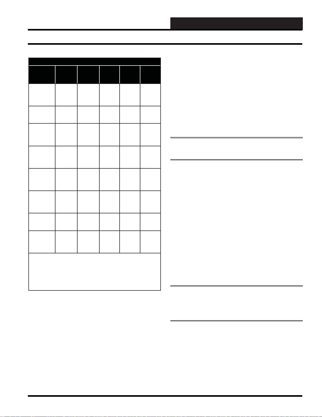
Box Fan Relay & Reheat Relay Staging Occupied Mode
Relays
Stage On
At
+0.5 F
Above
Box Heat
Setpoint
At Box
Heat
Setpoint
-1.0 F
Below
Box Heat
Setpoint
-2.0 F
Below
Box Heat
Setpoint
+1.0 F
Above
Box Heat
Setpoint
+1.0 F
Above
Box Heat
Setpoint
At Box
Heat
Setpoint
-1.0 F
Below
Box Heat
Setpoint
Note 1: The series fan will run continuously anytime the
VAVBOX TUC-2R controller is in occupied mode.
Note 2: The parallel fan will run whenever Space Heating Mode is
active. At all other times, the fan will only activate if the damper/airfl ow is below a user defi ned low limit setting.
Series
Fan
See
Note 1
See
Note 1
Parallel
Fan
See
Note 2
See
Note 2
Heat
Stage
1
X
X
Heat
Stage
2
X
X
Heat
Stage
3
X
X
Modulating (Proportional) Heat
The VAVBOX TUC-2R controller expansion board also provides
an analog output for control of a modulating hot water valve or
SCR electric heater. It provides a 0-10 VDC signal to control the
heating device. When the space temperature drops to 0.5 ºF above
the Heating Setpoint the output starts at 0 VDC and ramps up to 10
VDC at 1.5 ºF below the Heating Setpoint.
See Table 4-2: Relay Staging - Occupied Mode for a complete
layout of the various fan and heat relay staging points.
4-10
Table 4-2: Relay Staging Occupied Mode
WCC III Technical Guide
Page 13

4. SCUSCR.EXE SCREENS
WCC III V A V BOX III Operation Modes
Series Flow Fan T erminals
If the VAV/Zone Controller has been confi gured as a Series Fan
Powered terminal unit, the series fan relay will activate and run
the series box fan continuously anytime the VAVBOX TUC-2R
controller is in occupied mode.
In all cases, before the series box fan can be activated, the air
damper is driven fully closed and held that way for 30 seconds to
make sure the series box fan hasn’t inadvertently started to spin
backwards. Once the series box fan starts, it waits an additional
10 seconds to allow the fan to spin up before it starts to open the
damper and introduce airfl ow from the HVAC unit fan.
Parallel Flow Fan T erminals
On parallel fan powered terminal units, the fan will run whenever
Space Heating mode is active. At all other times, the fan will only
activate if the damper/airfl ow is below a user-defi ned low limit
setting. This causes it to be used as a make-up air source. When the
damper/airfl ow rises 15% above the low limit setpoint, the fan will
be deactivated if there are no heating stages active and no space
demand exists.
The check for main fan status setting has no effect on the Parallel
Fan box when in the occupied mode.
Unoccupied Mode Sequences
NOTE: For the Unoccupied Mode Sequences to work
correctly the VAV/Zone controller must be able to read the
Main Fan Status.
Space Vent Mode
This mode only applies to the Occupied Mode of operation.
If the equipment is in the Unoccupied Mode, then a lack of
heating or cooling demand would generate the Off Mode (not
displayed).
Off Mode (Not Displayed)
During unoccupied mode, the mode is considered ‘OFF’ if the
space temperature does not generate a heating mode or cooling
mode based on the unoccupied heating & cooling setpoints.
When using non-fan powered terminal units, the VAVBOX TUC2R controller damper will position itself in the Night/Reheat
minimum position. In order for fan powered terminal units to
position the damper to the Nite/Reheat minimum position, the
check for main fan status must be selected and the HVAC unit fan
must be operating. If check main fan status has not been selected
the damper will be in the fully closed position.
Space Cooling Mode
During Unoccupied Mode, the HVAC unit is normally off.
Unoccupied Space Cooling mode is initiated by the temperature in
the space rising to the Unoccupied Cooling Setpoint.
If the VAVBOX TUC-2R controller is in the Unoccupied Supply
Air Heating mode because one or more of the VAVBOX controllers
has a heating demand, and another VAVBOX controller has a
cooling demand, the damper/airfl ow for the VAVBOX controller
requiring cooling will position itself to provide the heating
minimum setpoint amount of air into the space. No modulation
open will occur because the space does not want the warm air
currently being supplied by the air handler.
When the VAVBOX TUC-2R controller is in the Unoccupied
Supply Air Cooling mode, the damper will be held at the Night/
Reheat minimum position until the space temperature begins to
rise above the cooling setpoint. As the space temperature rises to
within 0.5 ºF of the Unoccupied Cooling Setpoint, the damper/
airfl ow calculation causes the air valve to open proportionally until
the maximum setpoint is achieved at 1.5 ºF above the setpoint. This
is a 2 ºF proportional window starting 0.5 ºF below the cooling
setpoint to 1.5 ºF above the cooling setpoint.
The damper/airfl ow is never allowed to modulate outside the user
adjusted minimum setpoint and maximum setpoint. The maximum
damper/airfl ow setpoint applies to heating and cooling modes
of operation only. All of the modes have their own individual
minimum setting.
Series Flow Fan T erminals
If the VAVBOX TUC-2R controller has been confi gured as a
Series Fan Powered terminal unit and check for main status has
been selected, the series fan relay will activate and run the series
box fan continuously anytime the HVAC unit fan is running. The
series fan relay will activate and run the series box fan when the
space temperature rises to 0.5 ºF below the unoccupied cooling
setpoint anytime the HVAC unit fan is not running. The damper
will be held closed if the HVAC unit fan is not running and will be
held at the Nite/Reheat minimum until the space temperature rises
to 0.5 ºF below the unoccupied cooling setpoint if the HVAC unit
fan is running. If check for main fan status has not been selected,
the series fan relay will activate and run the series box fan when
the space temperature rises to 0.5 ºF below the unoccupied cooling
setpoint. The damper will be in the fully closed position until the
space temperature rises to 0.5 ºF below the unoccupied cooling
setpoint.
WCC III Technical Guide
4-11
Page 14

4. SCUSCR.EXE SCREENS
WCC III V A V BOX III Operation Modes
In all cases, before the series box fan can be activated, the air
damper is driven fully closed and held that way for 30 seconds to
make sure the series box fan hasn’t inadvertently started to spin
backwards. Once the series box fan starts, it waits an additional
10 seconds to allow the fan to spin up before it starts to open the
damper and introduce airfl ow from the HVAC unit fan.
NOTE: If check for main fan status is selected, the series fan
will activate any time the HVAC unit fan is operating.
Parallel Flow Fan T erminals
In the Unoccupied Cooling mode the parallel fan will be off
whether check for main fan status has been selected or not. If
check for mainfan status has been selected, the damper will be
held at the Nite/Reheat minimum until the space temperature
begins to rise to 0.5 ºF below the unoccupied cooling setpoint. If
check for main fan status has not been selected, the damper will
be held in the fully closed position until the space temperature
begins to rise to 0.5 ºF below the unoccupied the cooling
setpoint.
Space Heating Mode
During unoccupied mode, the HVAC unit is normally off.
Unoccupied Space Heating mode is initiated by the temperature in
the space falling below the Unoccupied Space Heating Setpoint.
If the VAVBOX TUC-2R controller is in the Unoccupied Supply
Air Cooling mode because one or more of the VAVBOX TUC-2R
controllers has a cooling demand and another VAVBOX controller
has a heating demand, the damper/airfl ow for the VAVBOX
controller requiring heating will position itself to provide the Night/
Reheat setpoint amount of air into the space. No modulation open
will occur because the space does not want the cold air currently
being supplied by the air handler.
When the VAVBOX TUC-2R controller is in the Unoccupied
Supply Air Heating mode, the damper will be held at the Night/
Reheat minimum position until the space temperature begins to fall
below the Unoccupied heating setpoint. As the space temperature
falls to 0.5 ºF above the unoccupied Heating Setpoint, the damper/
airfl ow calculation causes the air valve to open proportionally until
the maximum setpoint is achieved at 1.5 ºF below the setpoint.
This is a 2 ºF proportional window starting 0.5 ºF above the heating
setpoint to 1.5 ºF below the heating setpoint.
Heat mode, the box heat relays will be de-energized when the
VAVBOX TUC-2R controller is in Supply Air Heating mode. In
either confi guration, when the VAVBOX TUC-2R controller is
in the Supply Air Heating mode, the damper will modulate open
proportionally to the space demand. The proportional window for
the space temperature is 0.5 ºF above to 1.5 ºF below the heating
setpoint. This allows the space to take advantage of the warm
supply air in the duct.
If check for main fan status is not selected and the VAVBOX
terminal unit has auxiliary heat (baseboard heat etc.) that does not
require the HVAC unit fan to operate, reheat can be used without the
HVAC unit fan operating. If check for main fan status is selected,
the reheat will only operate when the HVAC unit fan is operating.
The VAVBOX TUC-2R controller can activate auxiliary heating
relays if the relay Expansion Board has been connected and the
correct number of heating stages (1,2, or 3) has been confi gured.
During demands for heat, the fi rst stage will activate whenever the
space temperature drops below the heating setpoint. The second
stage will activate if the space temperature falls 1.0 ºF below
the heating setpoint. The third stage will activate if the space
temperature falls 2.0 ºF below the heating setpoint. There is a twominute delay between staging. This prevents stages from activating
at the same time. Once a heating stage has been activated, it must
remain on for at least one minute. Once it has been deactivated, it
must remain off for at least two minutes. The third stage relay will
deactivate when the space temperature rises to within 1.0 ºF of the
heating setpoint. The second stage relay will deactivate when the
space temperature rises to the heating setpoint. The fi rst stage relay
will deactivate when the space temperature rises above the heating
setpoint by 1.0 ºF.
See Table 4-3: Relay Staging - Unoccupied Mode for a complete
layout of the various fan & heat relay staging points.
Modulating (Proportional) Heat
The VAVBOX TUC-2R controller expansion board also provides
an analog output for control of a modulating hot water valve or
SCR electric heater. It provides a 0-10 VDC signal to control the
heating device. When the space temperature drops to 0.5 ºF above
the Heating Setpoint the output starts at 0 VDC and ramps up to 10
VDC at 1.5 ºF below the Heating Setpoint.
As with the Occupied Mode of operation, two different
confi gurations are available for the Unoccupied Space Heating
mode. If the box is confi gured to allow reheat during HVAC Heat
mode, the reheat relays can be activated even when the VAVBOX
TUC-2R controller is in the Supply Air Heating mode. If the
box is confi gured not to allow reheat when the HVAC unit is in
4-12
WCC III Technical Guide
Page 15
4. SCUSCR.EXE SCREENS
WCC III V A V BOX III Operation Modes
Box Fan Relay & Reheat Relay Staging Unoccupied Mode
Relays
Stage On
At
+0.5 F
Above
Box Heat
Setpoint
At Box
Heat
Setpoint
-1.0 F
Below
Box Heat
Setpoint
-2.0 F
Below
Box Heat
Setpoint
+1.0 F
Above
Box Heat
Setpoint
+1.0 F
Above
Box Heat
Setpoint
At Box
Heat
Setpoint
-1.0 F
Below
Box Heat
Setpoint
Note 1: If check for main fan status is selected, the series fan will
activate any time the HVAC unit fan is operating.
Note 2: If the VAVBOX TUC-2R has been confi gured as a Parallel Fan
Powered terminal unit, the Parallel fan will run continuously when the
VAVBOX TUC-2R Controller is in the Space Heating mode no matter
whether check for main fan status has been selected or not.
Table 4-3: Relay Staging - Unoccupied Mode
Series Flow Fan T erminals
Series
Fan
See
Note 1
See
Note 1
Parallel
Fan
See
Note 2
See
Note 2
Heat
Stage 1
X
X
Heat
Stage 2
X
X
Heat
Stage 3
X
X
If the VAVBOX TUC-2R controller has been confi gured as a Series
Fan Powered terminal unit and check for main status has been
selected, the series fan relay will activate and run the series box
fan continuously anytime the HVAC unit fan is running. The series
fan relay will activate and run the series box fan when the space
temperature falls to within 0.5 ºF above the unoccupied heating
setpoint anytime the HVAC unit fan is not running. The damper
will be held closed if the HVAC unit fan is not running and will
be held at the Nite/Reheat minimum until the space temperature
falls to within 0.5 ºF above the unoccupied heating setpoint if the
HVAC unit fan is running. If check for main fan status has not
been selected, the series fan relay will activate and run the series
box fan when the space temperature falls to within 0.5 ºF above the
unoccupied heating setpoint and the damper will stay in the fully
closed position.
In all cases, before the series box fan can be activated, the air
damper is driven fully closed and held that way for 30 seconds to
make sure the series box fan hasn’t inadvertently started to spin
backwards. Once the series box fan starts, it waits an additional
10 seconds to allow the fan to spin up before it starts to open the
damper and introduce airfl ow from the HVAC unit fan.
NOTE: If check for main fan status is selected, the series fan
will activate any time the HVAC unit fan is operating.
Parallel Flow Fan T erminals
If the VAVBOX TUC-2R controller has been confi gured as a
Parallel Fan Powered terminal unit, the Parallel fan will run
continuously when the VAVBOX TUC-2R controller is in the
Space Heating mode no matter whether check for main fan
status has been selected or not. If check for main fan status is
selected, the damper will remain in the closed position until the
HVAC unit controller is broadcasting that the HVAC unit fan
is operating, regardless of whether it is calling for heat or not.
Once the broadcast is received, the damper will then move to
its Night/Reheat minimum position until the space temperature
begins to fall below 0.5 ºF above the unoccupied heating
setpoint. If check for main fan status has not been selected, the
damper will be held in the fully closed position until the space
temperature begins to fall below 0.5 ºF above the unoccupied
heating setpoint. When in Supply Air Heating mode, the damper
will modulate to maintain the Unoccupied Heating setpoint.
NOTE: For the VAVBOX TUC-2R controller to go
into Supply Air Heating mode the HVAC unit fan must
be operating and the Supply Air temperature must be the
deadband amount above the Space temperature.
WCC III Technical Guide
4-13
Page 16

4. SCUSCR.EXE SCREENS
WCC III V A V BOX III T enant Override Logs
Damper Control
The damper position is calculated by the mode and demand from
the space sensor. Included in this calculation is an Integral function.
This prevents the damper/airfl ow from stagnating at a position
somewhere above the setpoint because the supply air temperature
or duct pressure isn’t quite enough to satisfy the space at the
currently calculated proportional position. The Integral causes the
calculation to keep adding a small amount of the proportional error
back into the damper/airfl ow position each time a new position is
calculated. The amount the Integral adds back in is user adjustable.
This value is presented as a number between 0.0 and 100.0.
That means that if the integral is less than 10.0, you are adding a
percentage from 0 to 100% of the error back into the calculation.
If you increase the Integral above 10, you are adding more than
100% back in.
With just proportional control, a 1 ºF error would cause a 50%
increase in damper/airfl ow if the Integral is not included. (1 °F is
half of the 2 ºF Proportional Window.)
If you had set the Integral to 10, the calculation would add 2% to
the current damper/airfl ow calculation each time. The calculation
occurs once every 10 seconds, so it would take a little over 4
minutes to reach the programmed 100% maximum.
Example:
This sliding window allows the control to be much tighter on the
smaller terminal units than can be achieved on the larger terminal
units as far as CFM readings. On a large terminal unit, 25 CFM
may not be noticeable, but on a small terminal unit, 25 CFM may
be more than the minimum airfl ow setting for the space.
If the pressure sensor is disconnected or fails on a pressure
independent terminal unit, the damper position goes to 100% open
and the VAV/Zone controller generates a General TUC Alarm to
alert the user that a failure has occurred.
On either type of terminal unit, a space sensor failure will force the
damper to position itself to the 45% position and it will not change
until the sensor is repaired or replaced.
T enant Ov erride Logs
If you require tenant billing for push-button override usage, the
MCD has the ability to track the amount of override time generated
by each space sensor equipped with push-button override.
NOTE: The VAVBOX TUC-2R controller will go into an
override condition for the user programmed amount of time
when this button is pushed even if the unit is already in a
occupied condition.
1. 50% Remaining / 2% Integral = 25 Moves to get to a 100%
Maximum.
2. 25 Moves times 10 seconds = 250 seconds or a little over 4
minutes to reach the 100% maximum damper/airfl ow position.
Of course, different space temperature errors and different Integral
values cause this calculation to operate slower or faster. It is up to
the user to determine the optimum setting that provides the tightest
temperature control without causing the damper to continue to
hunt or modulate, causing premature wear of the actuator gears
and motor.
On pressure dependent terminal units, the damper position is
maintained to within ± 3% of the calculated position. No attempt
is made to position the damper exactly on the calculated position.
This reduces wear and tear on the actuator gears and motors, and
the amount of airfl ow involved is not affected by that small amount
of damper error.
On pressure independent terminal units, the airfl ow is maintained
to within roughly 3% of the terminal unit size constant but no
tighter than 16 CFM on the smallest terminal units. The actual
control window is based on the formula:
Window = Terminal unit size X Square Root (1 / 750), where
Terminal unit size refers to the total rated CFM of the terminal
unit.
Storing and retrieving these logs requires a dedicated front end
computer running the WCC III Trendlog front-end software
program. No other method exists for retrieving these logs. That
means that all of your VAV/Zone controllers will be connected
together on the communications loop and the loop will be terminated
at a Satellite device which is connected to another communications
loop that is terminated at an on-site MCD computer. The tenant
logs are kept on the dedicated job site computer’s hard drive. The
only limitation to the number of logs stored is the capacity of the
hard drive on the computer to which it is being logged.
NOTE: There is also a Tenant Override software that can
be programmed that tenants can use to turn on multiple
zones(among other things) at once without having to use the
push button override on the space sensor. See Section 6 of the
WCC III manual for detailed operation of this program.
WARNING: This WCC III - MCD computer must be on 24
hours a day, 7 days a week, running the Backtask.exe software
in order for tenant logging to be tracked. The tenant logs are
kept on the dedicated end user job site computer’s hard drive.
The only limitation to the number of logs stored is the capacity
of the hard drive on the computer they are being logged to.
4-14
WCC III Technical Guide
Page 17

4. SCUSCR.EXE SCREENS
WCC III V A V BOX III T rend Logging
Alarm Detection and Reporting
The VAVBOX TUC-2R controller continuously performs self
diagnostics during normal operations to determine if any operating
failures have occurred. These failures can be reported to the user in
several ways, depending on the type of system and options installed
by the user. If WCC III computer front-end software is installed,
the alarms will be reported on the Alarm summary screen of the
WCC3.exe program and will be logged to disk of the WCC III
- MCD. These system logs can be downloaded and viewed with
the WCC3Utilies.exe program. If the WCC III - MCD is set up to
Email out alarms, then the alarm can initiate an Email callout to
alert someone to the alarm condition. See the WCC III computer
front end WCC3.exe program operations manual for further
information on this topic.
Internal Trend Logging
The Satellite controller can maintain an Internal Trend Log which
records a fi xed set of values at an interval programmed by the user.
In order to utilize these logs, a computer with WCC III front-end
software installed must be able to communicate with the WCC III
system.
The available options for Satellite internal trend logging are:
Change of State, Run Time Total, Analog Trend, and Analog
Peaks. The Change of State trend log can log the on time and
date, and off time and date for up to 8 binary points per Satellite.
The Run Time Total trend log can log the total accumulated on
or off time in seconds, minutes, or hours of up to 8 binary points
within the satellite controller. The total amount of on time that can
be accumulated without being reset is 9999 seconds, minutes, or
hours. The Analog Trend log can log the current analog value for
up to 8 analog points within the satellite. The timed interval for the
Analog Trend logging can be from 1 to 99 minutes, or from 1 to
99 hours. The Analog Peaks trend log will record the time, date,
and value of the Last Low Peak and the time, date, and value of the
Last High Peak for up to 8 analog points.
On the Change of State and Analog Trend there are 48 log
positions available. Once the last (48th) position has been recorded,
depending on how the user programs the log, it can Roll(saving the
latest and deleting the oldest), or stop until the log is reset. This
means the user is required to retrieve the logs at an interval that is
shorter than the duration of the last 48 logs.
The items that can be logged in the log are listed below:
• Date (Automatic)
• Time (Automatic)
• Space Temperature (Analog Input “AX” with X =
1 to 8)
• Date and Time of latest High and Low Space
Temperature Peaks
• Cooling/Heating Demand (Data Register A
(“RXA” with X = 1 to 8)) Note: This point will
read out as a whole number with no decimal,
examples: a 3.4 cooling demand will read out 34, a
2.5 heating demand will read out -25
• Supply Air Temperature (User programmable
Global Analog “GAXXX” with X = 1 to 256)
• Push Button Override Status (Logic Switch/Input
“LX” with X = 1 to 8)
• Airfl ow on Pressure Independent Terminal Units
(Data Register B (“RXB” with X = 1 to 8))
• Damper Position (Analog Output “PX” with x = 1
to 8)
For more information on Internal Trend Logging, see chapter 3 of
the WCCIII manual.
CAUTION: These logs are subject to loss if a long power
outage occurs because there is no battery backed memory
on the VAVBOX controller. These values are stored on the
Satellite controller and its memory may only last up to 3 days.
External Trend Logging
Any addressable point on the WCC III system is capable of being
trend logged with the WCC3Trendlog.exe program. See section 8
for further details.
Shown below are some log intervals and the duration of 48 logs.
1 Minute Interval .......................... 48 Minute Duration
15 Minute Interval ........................ 12 Hour Duration
30 Minute Interval ........................ 24 Hour Duration
60 Minute Interval ........................ 48 Hour Duration
8 Hour Interval ...............................16 Day Duration
WCC III Technical Guide
4-15
Page 18

4. SCUSCR.EXE SCREENS
WCC III V A V BOX III F orce Modes
Force Modes or Overrides
The VAVBOX TUC-2R controller damper can be forced to
one of several positions. These force modes aid the user during
troubleshooting or air balancing, etc.
• Force Damper Full Open (Ignores Airfl ow
Reading)
• Force Damper Full Closed (Ignores Airfl ow
Reading )
• Force to Maximum Airfl ow/Damper Setpoint
• Force to Minimum Airfl ow/Damper Setpoint (for
the current Supply Air Mode)
• Force to Fixed Airfl ow/Damper Setpoint
• Force Damper to Re-Calibrate
The Force to Fixed Airfl ow/Damper mode also has a setpoint
associated with it. This allows the user to provide a non-changing
fi xed amount of air into the space that doesn’t affect the Minimum
or Maximum setpoints. That means the user doesn’t have to disturb
the real minimum and maximum setpoints to achieve a nonstandard
setting during their troubleshooting or air balancing modes.
The Force to Minimum mode uses the currently active minimum
setting based on the Supply Air Neutral, Cooling, or Heating
modes. Whatever mode the VAVBOX TUC-2R controller is in sets
the minimum used by the force mode.
The damper force modes will remain in effect until cancelled by the
user or until the power is removed. There are no force commands
available for the auxiliary relays.
Fan
Parallel
Fan
Heat
4-16
WCC III Technical Guide
Page 19

SCUSCR.EXE SCREENS
VAV BOX CONTROLLER
Satellite: _ 4 Unit: 1 Location: Version: 3.04
TYPE OF CONTROL METHOD: XXXXX XXXXX XXXXX
[ STATUS SCREEN ] [ EXPANSION OUTPUTS ]
{ Optional }
Operating Mode: OCCUPIED MODE
Space Temp Mode: VENT MODE Fan Status.......: OFF
Supply Air Mode: COOLING MODE
Heat Relay.......: OFF
Space Temperature...............: 76.2°F
Active Cooling Setpoint.........: 72.0°F Heat Relay.......: OFF
Active Heating Setpoint.........: 70.0°F
Current Heat/Cool Demand........: 4.2°F Proportional Heat: 0%
Sensor Slide Adjust...{Optional}: 0.0°F
EMS Effect on Setpoints.........: 0 %
Supply Air Temperature..........: 55.0°F
Discharge Temperature...........: 55.0°F
Airflow.........{Pr.Indep. ONLY}: 0 CFM Main Fan Status..: OFF
Calculated Damper/Airflow.......: 54%
Damper Position.................: 56%
< Ctrl-RIGHT ARROW > for Setpoints Screen File: SCR220.SDF
The SCUSCR.exe program is used to access stand-alone controllers
that have been preprogrammed with application-specifi c software
such as VAVBOX software, AHU control software, Heat Pump
control software, etc. These screens are displayed the same as the
older WCC II screens.
NOTE: Only the VAV BOX III software is explained in this
section.
V AV BO X III for WCC III Softw are
Screens
4. SCUSCR.EXE SCREENS
V AV BO X III Status Screen
Figure 4-1: VA V BOX Status Screen
This is the main summary screen for the WCC3 VAV BOX III
software for the WCC III system and there should be suffi cient
information on this screen that by simply viewing of this screen
an operator can detect if the VAV BOX III controller is operating
correctly or not.
Satellite: Unit:
The satellite fi eld is used to input a valid SAT 3d address number.
The unit number is used to select a valid TUC (Terminal Unit
Controller) that is connected to the SAT 3d controller.
WCC III Technical Guide
Valid SAT 3d addresses are in groups of 4, starting at address 4.
You cannot start a SAT 3d address with a 5, 6, 7, 9, 10, 11, 13,
14, 15 etc. It must be a derivative of address 4, example 4, 8, 12,
16, 20, 24, 28,etc. If there is a question with Satellite addressing,
please check the Satellite summary screen to see if a valid SAT 3d
exists before continuing.
4-17
Page 20
4. SCUSCR.EXE SCREENS
V AV BO X III Status Screen
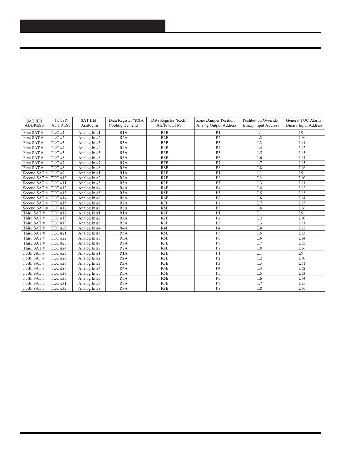
Each Sat3d uses up the address space of the equivalent of 4 regular
SAT III controllers. See Table 4-4: “SAT3d Addressing to TUC
control points” for a further explanation.
Certain TUC control points have been shoehorned into SAT 3d
control points so that they may be used in global calculations.
Table 4-4: SAT3d Addressing to TUC control points
4-18
WCC III Technical Guide
Page 21

4. SCUSCR.EXE SCREENS
VAV BOX CONTROLLER
Satellite: _ 4 Unit: 1 Location: Version: 3.04
TYPE OF CONTROL METHOD: XXXXX XXXXX XXXXX
[ STATUS SCREEN ] [ EXPANSION OUTPUTS ]
{ Optional }
Operating Mode: OCCUPIED MODE
Space Temp Mode: VENT MODE Fan Status.......: OFF
Supply Air Mode: COOLING MODE
Heat Relay.......: OFF
Space Temperature...............: 76.2°F
Active Cooling Setpoint.........: 72.0°F Heat Relay.......: OFF
Active Heating Setpoint.........: 70.0°F
Current Heat/Cool Demand........: 4.2°F Proportional Heat: 0%
Sensor Slide Adjust...{Optional}: 0.0°F
EMS Effect on Setpoints.........: 0 %
Supply Air Temperature..........: 55.0°F
Discharge Temperature...........: 55.0°F
Airflow.........{Pr.Indep. ONLY}: 0 CFM Main Fan Status..: OFF
Calculated Damper/Airflow.......: 54%
Damper Position.................: 56%
< Ctrl-RIGHT ARROW > for Setpoints Screen File: SCR220.SDF
V AV BO X III Status Screen
Figure 4-1, cont.: VA V BOX Status Screen
Location
The Location fi eld is a user programmable fi eld name that is used
to identify the location of the WCC3 VAV BOX zone or space that
the WCC3 VAV BOX III is controlling. (There is space in this fi eld
Space Temp Mode:
There are four types of Space temperature control modes: Space
Cooling Mode, Space Heating Mode, Space Vent Mode, and Space
Off Mode
for 20 alphanumeric characters.)
Space Cooling Mode
Type of Control Method:
The “Type of Control Method:” message fi eld at the top of this
This mode occurs when the Space Temperature rises above the
Space Cooling Setpoint.
screen comes from the VAV BOX mode of operation, which is
Screen #4 of the (Ctrl – Right Arrow – Three times) of the VAV
Space Heating Mode
BOX setup screens. See Figure 4-5 for further details. There
are four possible messages displayed in this fi eld “Single Duct
Cooling”, “Heating/Cooling Change Over”, ”Series Fan Powered”,
This mode occurs when the Space Temperature falls below the
Space Heating Setpoint.
or Parallel Fan Powered.
Space Vent Mode
There are there three main combinatorial control modes of the
WCC3 VAV BOX III - Operating Mode, Space Temp mode, and
Supply Air mode. Control of the WCC3 VAV BOX III is dependent
upon a mixture of all three of these modes. See the sequence of
operation of the WCC3 VAV BOX III for further details.
Operating Mode:
There are three main operating modes that can be listed here. They
are Occupied, Unoccupied, and Override Occupied
WCC III Technical Guide
This mode occurs when the Space Temperature is between the
Cooling Setpoint and the Heating Setpoint.
Space Off Mode
During unoccupied mode, the mode is considered “OFF” if the
space temperature does not generate a heating mode or cooling
mode based on the unoccupied heating & cooling setpoints.
4-19
Page 22

4. SCUSCR.EXE SCREENS
V AV BO X III Status Screen
Supply Air Mode:
There are three types of Supply Air Modes: Supply Air Cooling
Mode, Supply Air Heating Mode, and Supply Air Neutral Mode.
Supply Air Neutral Mode
This mode occurs when the Supply Air Temperature is between
the heating and cooling deadband amounts.
Supply Air Cooling Mode
This mode occurs when the Supply Air Temperature falls the
deadband amount below the space temperature. To cancel the
supply air cooling mode, the supply air temperature must rise to
within 2 ºF of the space temperature.
Supply Air Heating Mode
This mode occurs when the Supply Air Temperature rises the
deadband amount above the space temperature. To cancel the
supply air heating mode, the supply air temperature must fall to
within 2 ºF of the space temperature.
Space Temperature
This is the current temperature of the zoned area that the WCC3
VAVBOX III is controlling. It is listed in degrees Fahrenheit.
(Zone temperatures sensors WM Part# OE210, OE211, OE212,
or OE213) A duct sensor in the return air ducting may also be used
for return air control of the VAVBOX zone (WM Part# OE230 or
OE231).
Active Cooling Setpoint
This is the current cooling setpoint that the VAV BOX III software
is controlling to. This setpoint is dependent on “Occupied” or
“Unoccupied” conditions. It is listed in degrees Fahrenheit.
Active Heating Setpoint
This is the current heating setpoint that the VAV BOX III software
is controlling to. This setpoint is dependent on “Occupied” or
“Unoccupied” conditions. It is listed in degrees Fahrenheit.
Current Heat / Cool Demand
This is the current heating or cooling demand for the VAV Box
controller in degrees from the current setpoint. This current setpoint
could be the occupied cooling or heating setpoint or the unoccupied
cooling or heating setpoint. It is listed in degrees Fahrenheit.
Sensor Slide Adjust ….(Optional)
If the zone temperature sensor that is connected to the VAV BOX
controller is equipped with a Slide offset pot, (WM Part # OE212,
or OE213) for tenant comfort control of space temperature, then
this fi eld value will range from “0” to “5”, with 0 being disabled,
and 1, 2, 3, 4, and 5, being the degrees in Fahrenheit, both plus
and minus from the programmed heating or cooling setpoint
depending on the current mode of operation of the WCC3 VAV
BOX III controller.
EMS Effect on Setpoints
On a command from the WCC III – MCD central processor,
typically during peak load demand periods, the Terminal Unit
Controller (TUC-2R) will increase the cooling setpoint and also
decrease the heating setpoint by an amount programmed by the
system operator. The amount of increase/decrease that can be
programmed is 0-10 ºF.
Supply Air Temperature
This is used to determine if the main VAV system is in a heating or
cooling mode. VAV BOX zones so equipped with reheat can use
cool air and then “Reheat” it back up to temperature for desired
heating of the zone. These “reheated” zones are usually located
on the outer perimeter of a building’s heating or cooling needs.
This is because interior zones generally require cooling-only type
of control.
Discharge Air Temperature
If the VAV BOX is so equipped with a stage or multiple stages of
reheat, it can then affect the temperature output of the VAV BOX.
An input on the VAV BOX controller must then be used to measure
this outgoing temperature from the VAV BOX.
Airfl ow ….. {Pr. Indep. ONLY}
This is the current airfl ow calculation in CFM (Cubic Feet per
Minute).
Calculated Damper/Airfl ow
In pressure independent systems, you may want to have a set CFM
level in the zoned space.
4-20
WCC III Technical Guide
Page 23

4. SCUSCR.EXE SCREENS
V AV BO X III Status Screen
Damper Position
This is a percentage of “OPEN” for the actuator and this
corresponds to how much the air valve is open to let conditioned
air into the space. 10 % and the air valve is open very little; 100 %
and the air valve is fully open. Please note that there are different
manufacturers of air valves, and these air valves can be of the 60
or 90 Degrees type on the rotation to fully open these air valves.
WattMaster VAV BOX III works with both of these types of air
valves.
EXP ANSION OUTPUTS (Optional)
There is a relay expansion board that can be used with the WCC III
VAV BOX controller.
This relay expansion board (WM part # OE322) has 3 relays and
an analog output for control of an analog valve for hot water or
steam heating via a modulating steam or hot water valve. This
modulating output voltage can supply a 0-10 Volts DC signal for
proportional control of the modulating steam or hot water valve.
Fan Status ….. XXX
The status of the fan may be either “ON” or “OFF” depending on
the type of VAV BOX that has been selected and if it is in occupied
or unoccupied mode.
Heat Relay ….. XXX
The status of the 1st stage of reheat relay may be either “ON” or
“OFF” depending on the type of VAV BOX that has been selected
and if it is in occupied or unoccupied mode.
Heat Relay ….. XXX
The status of the 2nd stage of reheat relay may be either “ON” or
“OFF” depending on the type of VAV BOX that has been selected
and if it is in occupied or unoccupied mode.
Proportional Heat: XX%
The status in a percentage of open of the proportional hot water
valve is listed here. This may be dependent on the type of VAV
BOX that has been selected and if it is in occupied or unoccupied
mode.
Main Fan Status ….. XXX
The status of the main fan may be either “ON” or “OFF”
depending on the status that comes from a Global Analog (1 to
256) that is programmed on the VAVBOX Global Screen. See
fi gure 4-4.
NOTE: There are no force commands that are available for
these three auxiliary relays or the Proportional heat output
voltage.
WCC III Technical Guide
4-21
Page 24

4. SCUSCR.EXE SCREENS
VAV BOX CONTROLLER
Satellite: _ 4 Unit: 1 Location: Version: 3.04
[ SETPOINT SCREEN ] [ DAMPER / AIRFLOW SETTINGS ]
Occupied Cooling Setpoint.......: 76°F { % = Pr Dep CFM = PR Indep }
Occupied Heating Setpoint.......: 70°F
Unoccupied Cooling Setpoint.....: 80°F Maximum In All Modes: 100 %
Unoccupied Heating Setpoint.....: 65°F Vent Minimum........: 50 %
Supply Air HVAC Mode Deadband...: 0°F Cool Minimum........: 10 %
Maximum EMS Effect on Setpoints.: 0°F Heat Minimum........: 15 %
Maximum Sensor Slide Adjustment.: 2°F Nite/Reheat Minimum.: 25 %
Push-button Override Duration...: 4 Hr Fixed Damper/Airflow: 0 %
Damper Control Integral {Ki}....: 0 Fan On {PF Boxes}...: 0 %
[ CONFIGURATION ]
Damper Operation........{0 = Direct Acting 1 = Reverse Acting}: 1
Stages of Box Heat.............................................: 2
Allow Box Heat to Remain On in HVAC Heat Mode {0 = No 1 = Yes}: 1
This Box Needs the Main Fan Status ...........{0 = No 1 = Yes}: 1
Box Size Constant for Airflow @ 1"WG..........{ Pr Indep ONLY }: 0 CFM
< Ctrl-RIGHT ARROW > for Setpoints Screen File: SCR220.SDF
< Ctrl-LEFT ARROW > for Status
V AV BO X III Setpoint Screen
Figure 4-2: VA V BOX Setpoint Screen
Occupied Cooling Setpoint is the temperature setpoint
that you wish to control the Zone’s space temperature to during
occupied times when the main air handler is turned on and in the
the Supply Air HVAC Mode deadband is 5 and the current room
temperature is 70 ºF then the supply air temperature would need to
be under 65 ºF for the Supply Air Mode to be in Cooling Mode.
COOL mode of operation. The damper will modulate the actuator
to control the temperature in the space.
Maximum EMS Effect on Setpoints - On a command from
the WCC III – MCD central processor, typically during peak load
Occupied Heating Setpoint is the temperature setpoint
that you wish to control the Zone’s space temperature to during
occupied times when the main air handler is turned on and in the
HEAT mode of operation. The damper will modulate the actuator
demand periods, the Terminal Unit Controller (TUC-2R) will
increase the cooling setpoint and also decrease the heating setpoint
by an amount programmed by the system operator. The amount of
increase/decrease that can be programmed is 0-10 ºF.
to control the temperature in the space.
Maximum Sensor Slide Adjustment - Enter a value of 0 to
Unoccupied Cooling Setpoint is the temperature setpoint
that you wish to control the Zone’s space temperature to during
unoccupied times when the main air handler is turned on and in the
COOL mode of operation. The damper will modulate the actuator
5 that corresponds to 0 to 5 degrees F. This allows the tenant to
remotely adjust the setpoint in his or her zone. There has to be a
sensor with a slide pot on it in order for this to work, and this sensor
must be properly wired back into the TUC-2R controller.
to control the temperature in the space.
Unoccupied Heating Setpoint is the temperature setpoint
that you wish to control the Zone’s space temperature to during
unoccupied times when the main air handler is turned on and in the
HEAT mode of operation. The damper will modulate the actuator
to control the temperature in the space.
Supply Air HVAC Mode Deadband is the value that is added
to or subtracted from the space temperature to determine the
supply air mode. This value can be between 2 and 20. For example
if the Supply Air HVAC Mode deadband is 5 and the current room
temperature is 70 ºF then the supply air temperature would need to
be over 75 ºF for the Supply Air Mode to be in Heating Mode. If
4-22
Pushbutton Override Duration - Enter a value of 0 to 24
that corresponds to 0 to 24 hours for the override to have in effect.
This allows the tenant in the space to remotely turn the zone from
unoccupied mode to occupied mode. NOTE: The maximum
amount of time that can be programmed may vary on different
types of software.
Damper Control Integral {Ki} - The “Damper Control
Integral{Ki}” is the speed at which the control loop within the
electronic controls that is controlling the electronic actuator will
actually modulate the damper for temperature control / CFM
control. See the sequence of operation under the “Damper Control”
heading for further explanation of how exactly the “Damper
Control Integral {Ki}” works.
WCC III Technical Guide
Page 25

4. SCUSCR.EXE SCREENS
V AV BO X III Setpoint Screen
[ Damper / Airfl ow Settings ]
____________________________
{ % = PR Dep CFM = PR Indep }
Damper / Airfl ow Settings are expressed as a percentage
of damper open with pressure dependant zone boxes. Pressure
Independent Zone boxes are in CFM (Cubic Feet per Minute).
Maximum in All Modes
This is the maximum position that the air valve will go to in ALL of
the seven different modes.
These maximum values are expressed
in damper open percentages for pressure dependent terminal units
or in CFM for pressure independent terminal units.
Enter a value of
0 to 100 that corresponds to the maximum airfl ow.
Cooling Minimum
When the HVAC unit is in the Supply Air Cooling mode but the
space does not require cooling, the VAVBOX damper will go to the
Cooling Minimum position. These minimum values are expressed
in damper open percentages for pressure dependent terminal units
or in CFM for pressure independent terminal units.
Heating Minimum
When the HVAC unit is in the Supply Air Heating mode but the
space does not require Heating, the VAVBOX damper will go to the
Heating Minimum position. These minimum values are expressed
in damper open percentages for pressure dependent terminal units
or in CFM for pressure independent terminal units.
the HVAC unit is in Supply Air Heating mode, the VAVBOX
damper will modulate as required to maintain the Space Heating
setpoint.
Unoccupied Mode
When using non-fan powered terminal units, the VAVBOX damper
will position itself in the Nite/Reheat minimum position. In order
for fan powered terminal units to position the damper to the Nite/
Reheat minimum position, the check for main fan status must be
selected and the HVAC unit fan must be operating.
Fixed Damper/Airfl ow
This setting allows the user to set a “Fixed” position for the air
valve. These minimum values are expressed in damper open
percentages for pressure dependent terminal units or in CFM for
pressure independent terminal units.
Fan On (PF fan Box es)
This is a minimum CFM setting for the Parallel Fan. If the CFM
drops below this setting for approximately 10 minutes then the
Parallel fan will start to increase the CFM through the VAVBOX.
Damper Operation
There are two possible choices for this fi eld. Enter a 0 for Damper
Direct Acting operation or enter a 1 for Damper Reverse Acting
operation. If the actuator is clockwise to open, then “0” (ZERO)
should be selected. If the actuator is counter-clockwise to open,
then “1” (ONE) should be selected.
Vent Minimum
This is the minimum position the VAVBOX damper will move to
when the HVAC unit is in the Supply Air Neutral mode. These
minimum values are expressed in damper open percentages
for pressure dependent terminal units or in CFM for pressure
independent terminal units.
Nite/Reheat Minimum
This setpoint has two different functions depending on whether the
HVAC unit is in Occupied or Unoccupied mode. These minimum
values are expressed in damper open percentages for pressure
dependent terminal units or in CFM for pressure independent
terminal units.
Occupied Mode
If the VAVBOX TUC-2R controller is used on a non-fan powered
terminal unit that has reheat, the VAVBOX damper will move to
the Nite/Reheat position whenever a Space Heating demand occurs
and the HVAC unit is in Supply Air Cooling or Vent modes. When
WCC III Technical Guide
Stages of Bo x Heat
This confi gures the 2nd and 3rd relay on the relay expansion
board. We allow for up to 3 (three) stages of reheat for the four
different types of VAVBOX control. Entering a 0 confi gures the
relay expansion board to no stages of box heat, 1 corresponding
to 1 stage of box heat, 2 corresponding to 2 stages of box heat,
and 3 corresponding to 3 stages of box heat. See the sequence of
operation under the “Space Heat Mode” heading for further details
on specifi c operation.
Allow Box Heat to R emain On in HVAC Mode
If the VAV box that you are using has reheat, confi guring this
setting will allow the VAV box heat to operate at the same time as
the HVAC unit heat. Options available are: 0 = No; 1 = Yes.
4-23
Page 26

4. SCUSCR.EXE SCREENS
V AV BO X III Setpoint Screen
Box Size Constant for Airfl ow @ 1”WC
If this is a pressure independent box, this option allows you to
calibrate the box CFM correctly using the VAV box manufacturer’s
“K” factor. This “Box Size Constant for Airfl ow @ 1”WC” fi eld
is needed whenever you wish to have a pressure independent
operation of your VAV BOX. You must also have an Airfl ow
sensor attached to the VAV Box controller and have airfl ow fi ttings
connected to a airfl ow pickup tube. This fi eld requires that you
have from the VAV box manufacturer a chart, or at least a number,
that you then can fi ll in this fi eld. You must enter the correct “K”
(CFM) factor for the inlet diameter of the box you are confi guring.
For demonstration purposes, the TempMaster VAV box CFM
Sizing chart is shown below.
NOTE: VAVBOX controllers will automatically operate as
Pressure Independent if the Box Size Constant is greater then
0 CFM.
Figure 4-3: TempMaster Corporation VAV BOX CFM Sizing Chart
4-24
WCC III Technical Guide
Page 27

4. SCUSCR.EXE SCREENS
VAV BOX CONTROLLER
Satellite: _ 4 Unit: 1 Location: Version: 3.04
[ GLOBAL BINARIES ]
Unit operates in Occupied Mode when............: W1 is active.
Force Damper Fully Open when GB(x).............: GB1 is active.
Force Damper Fully Closed when GB(x)...........: GB10 is active.
Force Damper to Maximum when GB(x).............: GB11 is active.
Force Damper to Minimum when GB(x).............: GB12 is active.
Force Damper to Fixed Damper/Airflow when GB(x): //// is active.
Force Damper to Re-Calibrate when GB(x)........: GB13 is active.
[ GLOBAL ANALOGS ]
Duct Temperature is read on GA (x).............: ////
EMS Setpoint Spread Precentage is read on GA(x): ////
Main Fan Status to read on GA(x)...............: GA12
[ CALIBRATION ]
Space Temp Sensor Calibration Offset...........: 0.0°F
Discharge Sensor Calibration Offset............: 0.0°F
< Ctrl-Right Arrow > for Next Page Screen File: SCR220.SDF
< Ctrl-Left Arrow > for Previous Page
V AV BO X III Globals Screen
Figure 4-4: VA V BOX Globals Screen
V AV BO X Globals Screen
The VAV BOX Globals Screen is used to set up the occupied/
unoccupied conditions for the control of the zone and forced
overrides of the damper for special “set” conditions. The calibration
offsets for the zone’s space and discharge temperature sensors can
also be set on this screen.
Unit operates in Occupied Mode when…………....:
This ON/OFF value is used to set week schedule/optimal start for
the occupied or unoccupied status of the VAV BOX III zone. Valid
Inputs for this fi eld are: 0, 1, GB1 to GB512, W1 to W128, S1 to
S128.
Force Damper Fully Open when GB(x) …………..:
The VAVBOX TUC-2R controller damper can be globally forced
to one of several positions with the use of Global Binaries. There
may be times at which the end user will want to have maximum
airfl ow in the conditioned zoned space. Such forced overrides
could include Global binary determinations for morning warmup,
troubleshooting, air balancing, CO2 reduction, pre-cooling or preheating for a meeting room, smoke detection (Remember that the
WCC III is not rated for fi re life safety) etc. On a Global force
mode it will be possible to force multiple VAVZONE boxes open or
closed with a single global command. (Ignores Airfl ow Reading.)
WCC III Technical Guide
Force Damper Fully Closed when GB(x) ………....:
The VAVBOX TUC-2R controller damper can be globally forced
to one of several positions with the use of Global Binaries. There
may be times at which the end user will want to have minimum
airfl ow in the conditioned zoned space. Such forced overrides
could include Global binary determinations for troubleshooting,
air balancing, night set back, smoke detection (Remember that the
WCC III is not rated for fi re life safety) etc. On a Global force
mode it will be possible to force multiple VAVZONE boxes open or
closed with a single global command. (Ignores Airfl ow Reading.)
Force Damper to Maximum when GB(x) ………....:
The VAVBOX TUC-2R controller damper can be globally forced
to one of several positions with the use of Global Binaries. There
may be times at which the end user will want to have maximum
airfl ow in the conditioned zoned space. Such forced overrides
could include Global binary determinations for morning warmup,
troubleshooting, air balancing, CO2 reduction, pre-cooling or
preheating for a meeting room, smoke detection (Remember that
the WCC III is not rated for fi re life safety) etc. On a Global force
mode it will be possible to force multiple VAVZONE boxes open or
closed with a single global command. (Ignores Airfl ow Reading.)
4-25
Page 28

4. SCUSCR.EXE SCREENS
VAV BOX CONTROLLER
Satellite: _ 4 Unit: 1 Location: Version: 3.04
[ GLOBAL BINARIES ]
Unit operates in Occupied Mode when............: W1 is active.
Force Damper Fully Open when GB(x).............: GB1 is active.
Force Damper Fully Closed when GB(x)...........: GB10 is active.
Force Damper to Maximum when GB(x).............: GB11 is active.
Force Damper to Minimum when GB(x).............: GB12 is active.
Force Damper to Fixed Damper/Airflow when GB(x): //// is active.
Force Damper to Re-Calibrate when GB(x)........: GB13 is active.
[ GLOBAL ANALOGS ]
Duct Temperature is read on GA (x).............: ////
EMS Setpoint Spread Precentage is read on GA(x): ////
Main Fan Status to read on GA(x)...............: GA12
[ CALIBRATION ]
Space Temp Sensor Calibration Offset...........: 0.0°F
Discharge Sensor Calibration Offset............: 0.0°F
< Ctrl-Right Arrow > for Next Page Screen File: SCR220.SDF
< Ctrl-Left Arrow > for Previous Page
V AV BO X III Globals Screen
Figure 4-4, cont.: VA V BOX Globals Screen
Force Damper to Minimum when GB(x) ……….…:
The VAVBOX TUC-2R controller damper can be globally forced
to one of several positions with the use of Global Binaries. There
may be times at which the end user will want to have minimum
airfl ow in the conditioned zoned space. Such forced overrides
could include Global binary determinations for troubleshooting,
air balancing, night set back, smoke detection (Remember that the
may be times at which the end user will want to re-calibrate the
actuator on the VAVBOX. Such forced overrides could include
troubleshooting and air balancing.
Remember that there may be a mechanical problem with the
actuator or air valve damper, and you should always try to recalibrate the actuator before determining if the actuator is actually
bad or not.
WCC III is not rated for fi re life safety) etc. On a Global force
mode it will be possible to force multiple VAVZONE boxes open or
closed with a single global command. (Ignores Airfl ow Reading.)
Force Damper to Fixed Damper/Airfl ow when GB(x)..:
The VAVBOX TUC-2R controller damper can be globally forced
to one of several positions with the use of Global Binaries. There
may be times at which the end user will want to have fi xed
airfl ow in the conditioned zoned space. Such forced overrides
could include Global binary determinations for morning warmup,
troubleshooting, air balancing, CO2 reduction, pre-cooling or preheating for a meeting room, smoke detection (Remember that the
WCC III is not rated for fi re life safety) etc. On a Global force
mode it will be possible to force multiple VAVZONE boxes to
a fi xed position with a single global command. (Ignores Airfl ow
Reading.)
Force Damper to Re-Calibrate when GB(x) ………:
The VAVBOX TUC-2R controller damper can be globally forced
to one of several positions with the use of Global Binaries. There
4-26
Space Temp Sensor Calibration Offset ………….:
There is an option to change the calibration of a thermistor sensor
(Usually due to the position or location of the thermistor sensor)
a few degrees plus or minus from the actual temperature that the
thermistor sensor is actually reading. Acceptable values in this
fi eld are numerical with both positive and negative (+/-) values of
0 to 99. These values are in Degrees Fahrenheit.
Discharge Temp Sensor Calibration Offset ………….:
There is an option to change the calibration of a thermistor sensor
(Usually due to the position or location of the thermistor sensor)
a few degrees plus or minus from the actual temperature that the
thermistor sensor is actually reading. Acceptable values in this
fi eld are numerical with both positive and negative (+/-) values of
0 to 99. These values are in degrees Fahrenheit.
NOTE: If no duct sensor is attached then this will read the
same as the Supply Air Temperature.
WCC III Technical Guide
Page 29

4. SCUSCR.EXE SCREENS
VAV BOX CONTROLLER
Satellite: _ 4 Unit: 1 Location: Version: 3.04
[ MODE OF OPERATION ]
Enter the proper control method for the type of box installed: 3
0 = Single Duct Cooling Only
1 = Heating/Cooling Changeover
2 = Series Fan Powered
3 = Parallel Fan Powered
NOTE: Boxes will automatically operate as Pressure Independent if the
Box Size Contant is greater than 0 CFM.
Screen File: SCR220.SDF
< Ctrl- Right Arrow > for Previous Page
V AV BO X Mode of Operation Screen
Figure 4-5: VA V BOX Mode of Operation Screen
V AV Bo x Control Method
Set this setup confi guration item for the type of box that the
VAVBOX TUC-2R controller is to be used on. The options
available are:
0 = Cooling Only Box
1 = Heating/Cooling Changeover Box
2 = Series Fan Powered Box
3 = Parallel Fan Powered Box
The Cooling Only VAV BOX controllers have the option of having
Reheat only if the expansion board is installed.
WCC III Technical Guide
4-27
Page 30

4. SCUSCR.EXE SCREENS
V AV BO X II for WCC III Softw are Screen Descriptions
V AVBO X II for WCC III Softw are
Screens (WattMaster Software #SS5001)
Single Duct - Cooling Only
Sequence of Operation
The Terminal Unit Controller (TUC-2R) operates in the “Occupied”
mode unless switched to “Unoccupied” by a command from a
WCC III – MCD central processor. The optional tenant override
button on the space sensor overrides the WCC III – MCD central
processor from unoccupied mode to occupied mode.
On the initial power-up or when the Terminal Unit Controller (TUC2R) receives a calibrate command, the Terminal Unit Controller
(TUC-2R) actuator will drive to the full clockwise mechanical
stop and then back to the full counter clockwise mechanical stop in
order to determine where the maximum travel limits are.
Occupied Cooling Mode
The Terminal Unit Controller (TUC-2R) changes to the cooling
mode when the supply air temperature as sensed by the duct sensor,
or as received from the WCC III - MCD central processor, indicates
the supply temperature is below the space temperature. As the
space temperature rises above the cooling setpoint, the actuator
drives from it’s adjustable minimum to maximum position.
When the Terminal Unit Controller (TUC-2R) space temperature
is below the cooling setpoint, the Terminal Unit Controller (TUC2R) will position the damper actuator to the minimum position
setpoint. This minimum position setpoint may be changed by
the system operator at any position from zero to the maximum
damper position. When the Terminal Unit Controller (TUC-2R)
space temperature is 4 degrees F. or more above the setpoint, the
Terminal Unit Controller (TUC-2R) will position the damper
actuator to the maximum damper position setpoint. At any space
temperature between the temperature setpoint and setpoint plus 4
degrees F, the Terminal Unit Controller (TUC-2R) damper actuator
is proportional to the deviation from setpoint.
Unoccupied Mode
In the unoccupied mode (Night time), the unoccupied heating and
unoccupied cooling setpoints are applied.
Force Mode
On a command from the WCC III - MCD central processor, the
Terminal Unit Controller (TUC-2R) damper actuator can be forced
to the full open position, or to the full closed position.
4-28
WCC III Technical Guide
Page 31

4. SCUSCR.EXE SCREENS
V AV BO X II for WCC III Softw are Screen Descriptions
EMS Offset
On a command from the WCC III – MCD central processor,
typically during peak load demand periods, the Terminal Unit
Controller (TUC-2R) will increase the cooling setpoint and also
decrease the heating setpoint by 2 ºF.
Options
If the Terminal Unit Controller (TUC-2R) space temperature
sensor is provided with an optional “Warmer/Cooler” offset
slide potentiometer, the occupants can change the Terminal
Unit Controller (TUC-2R) programmed setpoint plus or minus
an amount equal to the limit set by the system operator. If the
Terminal Unit Controller (TUC-2R) space temperature sensor
is provided with an optional “Tenant Override Button”, this will
allow the tenant to change from the unoccupied mode to override
mode for a time period that is determined by the system operator.
In the override mode, Terminal Unit Controller (TUC-2R) sends a
signal to the AHU controller indicating an “override”.
NOTE: The VAVBOX TUC-2R controller will go into an
override condition for the user programmed amount of time
when this button is pushed even if the unit is already in a
occupied condition.
Features
In addition to being able to set and monitor the Terminal Unit
Controller (TUC-2R) space temperature and its damper actuator
position, the system operator can read the amount of offset the
occupant has applied to the thermostat setpoint. The system
operator can also set alarm limits and schedules as well as trend
log space temperature, and hours of tenant override. The Heating/
Cooling demand for the Terminal Unit Controller (TUC-2R) is
also displayed.
WCC III Technical Guide
4-29
Page 32

4. SCUSCR.EXE SCREENS
Single Duct Cooling Only Screen
Single Duct Cooling-Only Screens
This is the main summary screen for the WCC3 VAV BOX II
software for the WCC III system, and there should be suffi cient
information on this screen that by simply viewing of this screen
an operator can detect if the VAV BOX II controller is operating
correctly or not.
Figure 4-6: Single Duct Cooling Only - Pressure Dependent Status Screen
Satellite: Unit:
The satellite fi eld is used to input a valid SAT 3d address number.
The unit number is used to select a valid TUC (Terminal Unit
Controller) that is connected to the SAT 3d controller.
Valid SAT 3d addresses are in groups of 4, starting at address 4.
You can not start a SAT 3d address with a 5, 6, 7, 9, 10, 11, 13,
14, 15 etc. It must be a derivative of address 4, example 4, 8, 12,
16, 20, 24, 28, etc. If there is a question with Satellite addressing,
please check the Satellite summary screen to see if a valid SAT 3d
exists before continuing.
Each SAT 3d uses up the address space of the equivalent of 4
regular SAT III controllers. See Table 4-4: “SAT 3d Addressing
to TUC control points” for a further explanation. Certain TUC
control points have been shoehorned into SAT 3d control points so
that they may be used in global calculations.
Location
The location fi eld is a user-programmable fi eld name that is used
to identify the location of the WCC3 VAVBOX zone or space that
the WCC3 VAVBOX II is controlling. (There is space in this fi eld
for 20 alphanumeric characters.)
Space Temperature
This is the current temperature of the zoned area that the WCC3
VAVBOX II is controlling. It is listed in degrees Fahrenheit.
(Zone temperatures sensors WM Part# OE210, OE211, OE212,
or OE213) A duct sensor in the return air ducting may also be used
for return air control of the VAVBOX zone (WM Part# OE230, or
OE231)
4-30
WCC III Technical Guide
Page 33

4. SCUSCR.EXE SCREENS
Single Duct Cooling Only Screen
Current Cooling Setpoint
This is the current cooling setpoint that the VAVBOX II software
is controlling to. This setpoint is dependent on “Occupied” or
“Unoccupied” conditions. It is listed in degrees Fahrenheit.
Cooling Demand
This is the current cooling demand for the VAVBOX controller in
degrees from the current setpoint. This current setpoint could be
the occupied or unoccupied cooling setpoint. It is listed in degrees
Fahrenheit.
Sensor Slide Effect….(Optional)
If the zone temperature sensor that is connected to the VAVBOX
controller is equipped with a slide offset pot, (WM part# OE212, or
OE213) for tenant comfort control of space temperature then this
fi eld value will range from “0” to “5”, with “0” being disabled, and
1, 2, 3, 4, and 5, being the degrees in Fahrenheit, both plus and minus
from the programmed heating or cooling setpoint depending on the
current mode of operation of the WCC3 VAVBOX II controller.
Duct Temperature
Each WCC3 VAVBOX II controller has an input for a Duct supply
air temperature probe. VAVBOX zones so equipped with reheat
can use cool air, and then “Reheat” it back up to temperature for
desired heating of the zone. These “reheated” zones are usually
located on the outer perimeter of a building’s heating or cooling
needs. This is because interior zones generally require cooling only
type of control.
Damper Position
This is percentage of “OPEN” for the actuator and this corresponds
to how much the air valve is open to let conditioned air into the
space. 10% and the air valve is open very little; 100% and the air
valve is fully open. Please note that there are different manufacturers
of air valves, and these air valves can be of the 60 or 90 Degrees
type on the rotation to fully open. WattMaster VAVBOX II works
with both of these types of air valves.
WCC III Technical Guide
4-31
Page 34

4. SCUSCR.EXE SCREENS
Single Duct Cooling Only Screen
Figure 4-7: Single Duct Cooling Only - Pressure Dependent Setpoint Screen
Occupied Cooling Setpoint
This is the temperature setpoint that you wish to control the Zone’s
space temperature to during occupied times when the main air
handler is turned on. The damper will modulate the actuator to
control the temperature in the space.
Unoccupied Cooling Setpoint
This is the temperature setpoint that you wish to control the Zone’s
space temperature to during unoccupied times when the main air
handler is turned on. The damper will modulate the actuator to
control the temperature in the space.
Maximum Sensor Slide Effect on Setpoints
Enter a value of 0 to 5 that corresponds to 0 to 5 degrees F. This
allows the tenant to remotely adjust the setpoint in his or her zone.
There has to be a sensor with a slide pot on it in order for this to
work, and this sensor must be properly wired back to the TUC-2R
controller.
Pushbutton Override Duration
Enter a value of 0 to 24 that corresponds to 0 to 24 hours for the
override to have in effect. This allows the tenant in the space to
remotely turn the zone from unoccupied mode to override mode.
NOTE: The VAVBOX controller will go into an override
condition for the user programmed amount of time when
this button is pushed even if the unit is already in a occupied
condition. The maximum amount of time that can be
programmed may vary on different types of software.
Damper Control Integral {Ki}
The “Damper Control Integral {Ki}” is the speed at which the
control loop within the electronic controls that is controlling the
electronic actuator that will actually modulate the damper for
temperature control / CFM control. 100 is fastest while 1 is slowest.
Normally should be set to 1.
4-32
WCC III Technical Guide
Page 35

4. SCUSCR.EXE SCREENS
Single Duct Cooling Only Screen
Minimum Damper Position
This is the minimum position that the actuator will close to. This
depends on calibration of the Zone’s damper actuator. This allows
for both types of VAV zone dampers, 60 degree boxes, and 90
degree boxes. This also allows for air balancing of the system.
Maximum Damper Position
This is the maximum position that the actuator will open to. This
depends on calibration of the Zone’s damper actuator. This allows
for both types of VAV zone dampers, 60 degree boxes, and 90
degree boxes. This also allows for air balancing of the system.
Vent Mode Damper P osition
This is the position the zone damper’s actuator will go to in the
vent mode of operation. The TUC-2R is in vent mode when the
Space Temperature is between the heating and cooling setpoints.
Unoccupied Mode Minimum Damper Position
This is the minimum position the zone damper’s actuator will go
to in the unoccupied mode of operation. This is determined by a
command from a WCC III – MCD central processor.
Damper Direct or Reverse Acting
If the actuator is clockwise to open, then “0” (ZERO) should be
selected. If the actuator is counter-clockwise to open, the “1”
(ONE) should be selected.
WCC III Technical Guide
4-33
Page 36

4. SCUSCR.EXE SCREENS
Single Duct Globals and Mode of Operation Screens
V AVBO X II Globals Screen
The VAVBOX II Globals Screen is used to set up the occupied/
unoccupied conditions for the control of the zone and forced
overrides of the damper for special “set” conditions. The calibration
offsets for the zone’s space and discharge temperature sensors can
also be set on this screen.
Figure 4-8: Single Duct Cooling Only - Pressure Dependent Globals Screen
Unit Operates in Occupied Mode when……
This ON/OFF value is used to set week schedule/optimal start for
the occupied or unoccupied status of the VAVBOX II zone. Valid
Inputs for this fi eld are: 0, 1, GB1 to GB512, W1 to W128, S1 to
S128.
Force Damper Fully Open when GB(X)
The VAVBOX TUC-2R controller damper can be globally forced
to one of several positions with the use of Global Binaries. There
may be times at which the end user will want to have maximum
airfl ow in the conditioned zoned space. Such forced overrides
could include Global binary determinations for morning warmup,
troubleshooting, air balancing, CO2 reduction, pre-cooling or pre-
heating for a meeting room, smoke detection (Remember that the
WCC III is not rated for fi re life safety) etc. On a Global force
mode it will be possible to force multiple VAVZONE boxes open or
closed with a single global command. (Ignores Airfl ow Reading)
Force Damper Fully Closed when GB(X)
The VAVBOX TUC-2R controller damper can be globally forced
to one of several positions with the use of Global Binaries. There
may be times at which the end user will want to have minimum
airfl ow in the conditioned zoned space. Such forced overrides
could include Global binary determinations for troubleshooting,
air balancing, night set back, smoke detection (Remember that the
WCC III is not rated for fi re life safety) etc. On a Global force
mode it will be possible to force multiple VAVZONE boxes open or
closed with a single global command. (Ignores Airfl ow Reading)
4-34
WCC III Technical Guide
Page 37

4. SCUSCR.EXE SCREENS
Single Duct Globals and Mode of Operation Screens
Force Damper to Maximum Setpoint when GB(X)
The VAVBOX TUC-2R controller damper can be globally forced
to one of several positions with the use of Global Binaries. There
may be times at which the end user will want to have maximum
airfl ow in the conditioned zoned space. Such forced overrides
could include Global binary determinations for morning warmup,
troubleshooting, air balancing, CO2 reduction, pre-cooling or preheating for a meeting room, smoke detection (Remember that the
WCC III is not rated for fi re life safety) etc. On a Global force
mode it will be possible to force multiple VAVZONE boxes open or
closed with a single global command. (Ignores Airfl ow Reading)
Force Damper to Minimum Setpoint when GB(X)
The VAVBOX TUC-2R controller damper can be globally forced
to one of several positions with the use of Global Binaries. There
may be times at which the end user will want to have minimum
airfl ow in the conditioned zoned space. Such forced overrides
could include Global binary determinations for troubleshooting,
air balancing, night set back, smoke detection (Remember that the
WCC III is not rated for fi re life safety) etc. On a Global force
mode it will be possible to force multiple VAVZONE boxes open or
closed with a single global command. (Ignores Airfl ow Reading)
Force Damper to Re-Calibrate when GB(X)……..
The VAVBOX TUC-2R controller damper can be globally forced
to one of several positions with the use of Global Binaries. There
may be times at which the end user will want to re-calibrate the
actuator on the VAVBOX. Such forced overrides could include
troubleshooting and air balancing.
Remember that there may be a mechanical problem with the
actuator or air valve damper, and you should always try to recalibrate the actuator before determining if the actuator is actually
bad or not.
Force Energy Management { EMS } Mode when
GB(X)…
The VAVBOX TUC-2R controller damper can be globally forced
into an Energy Management Mode, typically during peak load
demand periods, during this time the Terminal Unit Controller
(TUC-2R) will increase the cooling setpoint and also decrease the
heating setpoint by 2 ºF.
Duct Temperature can be read from Global
Analog……..
A Duct Air Temperature Sensor can be connected to the VAVBOX
TUC-2R or it can be read from a Global Analog. It should be
mounted in the supply duct close to the terminal unit where the
VAVBOX controller is installed. This sensor can be used for
monitoring purposes in place of the Duct Temperature Broadcast
from the MCD, otherwise the Duct Temperature will always read
the same as the Space Temperature.
NOTE: 1.) All temperature sensors must be Thermistor Type
III which provide 77.0 ºF @ 10K Ohms Resistance.
2.) The Duct Temperature Broadcast from the MCD must be in
a X,XXX format, no decimal place.
Space Temp Sensor Calibration Offset
There is an option to change the calibration of a thermistor sensor
(Usually due to the position or location of the thermistor sensor)
a few degrees plus or minus from the actual temperature that the
thermistor sensor is actually reading. Acceptable values in this
fi eld are numerical with both positive and negative(+/-) values of 0
to 99. These values are in degrees Fahrenheit.
SYSTEM DIAGNOSTICS
Powerup Count:
This is the number of times that the TUC-2R controller has reset
or has been repowered since the last time the powerup counter was
cleared.
Enable Counts:
The enable count fi eld is where you would enter a 1 to Clear/
Disable the powerup counter. You must set this value back to “0”
to enable the powerup counter to work again.
WCC III Technical Guide
4-35
Page 38

4. SCUSCR.EXE SCREENS
SINGLE DUCT COOLING ONLY VAV BOX { TUC-2R }
Satellite: _ 4 Unit: 1 Location: Version: 2.03
Analog Address Locations Logic Switch Definitions
A1 - Space Temperature L1 - Pushbutton Override Status
R1A - Cooling Demand
P1 - Damper Position
VAV BOX MODE OF OPERATION SELECTION
Enter Type of Box Desired....................................: 0
0 = Single Duct Cooling Only Box [ Pressure Dependent ]
1 = Single Duct Cooling Only Box [ Pressure Independent ]
2 = Parallel Fan Box w/Reheat [ Pressure Dependent ]
3 = Parallel Fan Box w/Reheat [ Pressure Independent ]
4 = Series Fan Box w/Reheat [ Pressure Dependent ]
5 = Series Fan Box w/Reheat [ Pressure Independent ]
6 = Heating/Cooling Changeover [ Pressure Dependent ]
7 = Heating/Cooling Changeover [ Pressure Independent ]
8 = Single Duct Cooling w/Reheat [ Pressure Dependent ]
9 = Single Duct Cooling w/Reheat [ Pressure Independent ]
NOTE: You must have an Airflow Sensor for Pressure Independent Boxes!
Press < HOME > for Main Menu
Press < Ctrl- Right Arrow > for Status Screen
Single Duct Globals and Mode of Operation Screens
Figure 4-9: Single Duct Cooling Only - Pressure Dependent Mode of Operation Screen
4-36
WCC III Technical Guide
Page 39

Single Duct Cooling Only Pressure Independent Status Screen
Single Duct Cooling-Only Screens –
Pressure Independent
This is the main summary screen for the WCC3 VAV BOX
II software for the WCC III system, and there should be
suffi cient information on this screen that by simply viewing of
this screen an operator can detect if the VAV BOX II controller
is operating correctly or not.
4. SCUSCR.EXE SCREENS
Figure 4-10: Single Duct Cooling Only - Pressure Independent Status Screen
Satellite: Unit:
The satellite fi eld is used to input a valid SAT 3d address
number. The unit number is used to select a valid TUC
(Terminal Unit Controller) that is connected to the SAT 3d
controller.
Valid SAT 3d addresses are in groups of 4, starting at address
4. You can not start a SAT 3d address with a 5, 6, 7, 9, 10, 11,
13, 14, 15 etc. It must be a derivative of address 4, example 4,
8, 12, 16, 20, 24, 28, etc. If there is a question with Satellite
addressing, please check the Satellite summary screen to see if
a valid SAT 3d exists before continuing.
Each SAT 3d uses up the address space of the equivalent
of 4 regular SAT III controllers. See Table 4-4: “SAT 3d
Addressing to TUC control points” for a further explanation.
Certain TUC control points have been shoehorned into SAT 3d
control points so that they may be used in global calculations.
Location
The location fi eld is a user-programmable fi eld name that is
used to identify the location of the WCC3 VAVBOX zone or
space that the WCC3 VAVBOX II is controlling. (There is
space in this fi eld for 20 alphanumeric characters.)
WCC III Technical Guide
4-37
Page 40

4. SCUSCR.EXE SCREENS
Single Duct Cooling Only Pressure Independent Status Screen
Space Temperature
This is the current temperature of the zoned area that the
WCC3 VAVBOX II is controlling. It is listed in degrees
Fahrenheit. (Zone temperatures sensors WM Part# OE210,
OE211, OE212, or OE213) A duct sensor in the return
air ducting may also be used for return air control of the
VAVBOX zone (WM Part# OE230, or OE231)
Current Cooling Setpoint
This is the current cooling setpoint that the VAVBOX II
software is controlling to. This setpoint is dependent on
“Occupied” or “Unoccupied” conditions. It is listed in degrees
Fahrenheit.
Cooling Demand
This is the current cooling demand for the VAVBOX controller
in degrees from the current setpoint. This current setpoint
could be the occupied or unoccupied cooling setpoint. It is
listed in degrees Fahrenheit.
Sensor Slide Effect….(Optional)
If the zone temperature sensor that is connected to the
VAVBOX controller is equipped with a slide offset pot,
(WM part# OE212, or OE213) for tenant comfort control
of space temperature then this fi eld value will range from
“0” to “5”, with “0” being disabled, and 1, 2, 3, 4, and 5,
being the degrees in Fahrenheit, both plus and minus from
the programmed heating or cooling setpoint depending on
the current mode of operation of the WCC3 VAVBOX II
controller.
Duct Temperature
Each WCC3 VAVBOX II controller has an input for a Duct
supply air temperature probe. VAVBOX zones so equipped
with reheat can use cool air, and then “Reheat” it back up to
temperature for desired heating of the zone. These “reheated”
zones are usually located on the outer perimeter of a building’s
heating or cooling needs. This is because interior zones
generally require cooling only type of control.
Current Airfl ow
This is the current airfl ow calculation in CFM (Cubic Feet per
Minute).
Calculated Airfl ow Setpoint
In pressure independent systems, you may want to have a set
CFM level in the zoned space.
Current Airfl ow Demand from Calculated Setpoint
In pressure independent systems, this calculation is in CFM
and is the current airfl ow calculation demand from the
Calculated Setpoint.
Damper Position
This is percentage of “OPEN” for the actuator and this
corresponds to how much the air valve is open to let
conditioned air into the space. 10% and the air valve is open
very little; 100% and the air valve is fully open. Please note
that there are different manufacturers of air valves, and these
air valves can be of the 60 or 90 Degrees type on the rotation
to fully open. WattMaster VAVBOX II works with both of
these types of air valves.
4-38
WCC III Technical Guide
Page 41

4. SCUSCR.EXE SCREENS
Single Duct Cooling Only Pressure Independent Setpoint Screen
Figure 4-11: Single Duct Cooling Only - Pressure Independent Setpoint Screen
Occupied Cooling Setpoint
This is the temperature setpoint that you wish to control the Zone’s
space temperature to during occupied times when the main air
handler is turned on. The damper will modulate the actuator to
control the temperature in the space.
Unoccupied Cooling Setpoint
This is the temperature setpoint that you wish to control the Zone’s
space temperature to during unoccupied times when the main air
handler is turned on. The damper will modulate the actuator to
control the temperature in the space.
Maximum Sensor Slide Effect on Setpoints
Enter a value of 0 to 5 that corresponds to 0 to 5 degrees F. This
allows the tenant to remotely adjust the setpoint in his or her zone.
There has to be a sensor with a slide pot on it in order for this to
work, and this sensor must be properly wired back to the TUC-2R
controller.
Pushbutton Override Duration
Enter a value of 0 to 24 that corresponds to 0 to 24 hours for the
override to have in effect. This allows the tenant in the space to
remotely turn the zone from unoccupied mode to override mode.
NOTE: The VAVBOX controller will go into an override
condition for the user programmed amount of time when
this button is pushed even if the unit is already in a occupied
condition. The maximum amount of time that can be
programmed may vary on different types of software.
Damper Control Integral {Ki}
The “Damper Control Integral {Ki}” is the speed at which the
control loop within the electronic controls that is controlling the
electronic actuator that will actually modulate the damper for
temperature control / CFM control. 100 is fastest while 1 is slowest.
Normally should be set to 1.
WCC III Technical Guide
4-39
Page 42

4. SCUSCR.EXE SCREENS
Single Duct Cooling Only Pressure Independent Setpoint Screen
Airfl ow @ 1” WG Box size
If this is a pressure independent box, this option allows you to
calibrate the box CFM correctly using the VAV box manufacturer’s
“K” factor. This “Box Size Constant for Airfl ow @ 1” WG” fi eld
is needed whenever you wish to have a pressure independent
operation of your VAVBOX. You must also have an Airfl ow
sensor attached to the VAV Box controller and have airfl ow fi ttings
connected to a airfl ow pickup tube. This fi eld requires that you
have from the VAV box manufacturer a chart, or at least a number,
that you then can fi ll in this fi eld. You must enter the correct “K”
(CFM) factor for the inlet diameter of the box you are confi guring.
For demonstration purposes, see Figure 4-3: TempMaster VAV
box CFM Sizing chart.
Minimum Airfl ow Setpoint
This is the minimum position in CFM that the actuator will close
to. This depends on calibration of the Zone’s damper actuator. This
allows for both types of VAV zone dampers, 60 degree boxes, and
90 degree boxes. This also allows for air balancing of the system.
Maximum Airfl ow Setpoint
This is the maximum position in CFM that the actuator will open
to. This depends on calibration of the Zone’s damper actuator. This
allows for both types of VAV zone dampers, 60 degree boxes, and
90 degree boxes. This also allows for air balancing of the system.
Vent Mode Airfl ow Setpoint
This is the position in CFM that the zone damper’s actuator will
go to in the vent mode of operation. The TUC-2R is in vent mode
when the Space Temperature is between the heating and cooling
setpoints.
Unoccupied Mode Minimum Airfl ow
This is the minimum position in CFM that the zone damper’s
actuator will go to in the unoccupied mode of operation. This
is determined by a command from a WCC III – MCD central
processor.
Damper Direct or Reverse Acting
If the actuator is clockwise to open, then “0” (ZERO) should be
selected. If the actuator is counter-clockwise to open, the “1”
(ONE) should be selected.
4-40
WCC III Technical Guide
Page 43

Single Duct Cooling Only Pressure Independent Globals Screen
V AVBOX II Globals Screen
The VAVBOX II Globals Screen is used to set up the occupied/
unoccupied conditions for the control of the zone and forced
overrides of the damper for special “set” conditions. The calibration
offsets for the zone’s space and discharge temperature sensors can
also be set on this screen.
4. SCUSCR.EXE SCREENS
Figure 4-12: Single Duct Cooling Only - Pressure Independent Globals Screen
Unit Operates in Occupied Mode when……
This ON/OFF value is used to set week schedule/optimal start for
the occupied or unoccupied status of the VAVBOX II zone. Valid
Inputs for this fi eld are: 0, 1, GB1 to GB512, W1 to W128, S1 to
S128.
Force Damper Fully Open when GB(X)
The VAVBOX TUC-2R controller damper can be globally forced
to one of several positions with the use of Global Binaries. There
may be times at which the end user will want to have maximum
airfl ow in the conditioned zoned space. Such forced overrides
could include Global binary determinations for morning warmup,
troubleshooting, air balancing, CO2 reduction, pre-cooling or preheating for a meeting room, smoke detection (Remember that the
WCC III is not rated for fi re life safety) etc. On a Global force
mode it will be possible to force multiple VAVZONE boxes open or
closed with a single global command. (Ignores Airfl ow Reading)
Force Damper Fully Closed when GB(X)
The VAVBOX TUC-2R controller damper can be globally forced
to one of several positions with the use of Global Binaries. There
may be times at which the end user will want to have minimum
airfl ow in the conditioned zoned space. Such forced overrides
could include Global binary determinations for troubleshooting,
air balancing, night set back, smoke detection (Remember that the
WCC III is not rated for fi re life safety) etc. On a Global force
mode it will be possible to force multiple VAVZONE boxes open or
closed with a single global command. (Ignores Airfl ow Reading)
WCC III Technical Guide
4-41
Page 44

4. SCUSCR.EXE SCREENS
Single Duct Cooling Only Pressure Independent Globals Screen
Force Damper to Maximum Setpoint when GB(X)
The VAVBOX TUC-2R controller damper can be globally forced
to one of several positions with the use of Global Binaries. There
may be times at which the end user will want to have maximum
airfl ow in the conditioned zoned space. Such forced overrides
could include Global binary determinations for morning warmup,
troubleshooting, air balancing, CO2 reduction, pre-cooling or preheating for a meeting room, smoke detection (Remember that the
WCC III is not rated for fi re life safety) etc. On a Global force
mode it will be possible to force multiple VAVZONE boxes open or
closed with a single global command. (Ignores Airfl ow Reading)
Force Damper to Minimum Setpoint when GB(X)
The VAVBOX TUC-2R controller damper can be globally forced
to one of several positions with the use of Global Binaries. There
may be times at which the end user will want to have minimum
airfl ow in the conditioned zoned space. Such forced overrides
could include Global binary determinations for troubleshooting,
air balancing, night set back, smoke detection (Remember that the
WCC III is not rated for fi re life safety) etc. On a Global force
mode it will be possible to force multiple VAVZONE boxes open or
closed with a single global command. (Ignores Airfl ow Reading)
Force Damper to Re-Calibrate when GB(X)……..
The VAVBOX TUC-2R controller damper can be globally forced
to one of several positions with the use of Global Binaries. There
may be times at which the end user will want to re-calibrate the
actuator on the VAVBOX. Such forced overrides could include
troubleshooting and air balancing.
Remember that there may be a mechanical problem with the
actuator or air valve damper, and you should always try to recalibrate the actuator before determining if the actuator is actually
bad or not.
Force Air Balance Mode to Activate when GB(X)
The VAVBOX TUC-2R controller damper can be globally forced
to one of several positions with the use of Global Binaries. This
mode is used for air balancing of the HVAC system. During this
mode the actuator will try to maintain the Current Airfl ow value to
the exact same value as the Current Calculated Airfl ow Setpoint by
constantly adjusting the damper. Normally the damper position is
maintained to +/- 3% of the Calculated position with no attempt to
position the damper exactly on the calculated position, this reduces
wear and tear on the actuator gears and motors, and the amount of
airfl ow involved is not affected by that small amount of damper
error.
Force Energy Management { EMS } Mode when
GB(X)…
The VAVBOX TUC-2R controller damper can be globally forced
into an Energy Management Mode, typically during peak load
demand periods, during this time the Terminal Unit Controller
(TUC-2R) will increase the cooling setpoint and also decrease the
heating setpoint by 2 ºF.
Duct Temperature can be read from Global
Analog……..
A Duct Air Temperature Sensor can be connected to the VAVBOX
TUC-2R or it can be read from a Global Analog. It should be
mounted in the supply duct close to the terminal unit where the
VAVBOX controller is installed. This sensor can be used for
monitoring purposes in place of the Duct Temperature Broadcast
from the MCD, otherwise the Duct Temperature will always read
the same as the Space Temperature.
NOTE: 1.) All temperature sensors must be Thermistor Type
III which provide 77.0 ºF @ 10K Ohms Resistance.
2.) The Duct Temperature Broadcast from the MCD must be
in a X,XXX format, no decimal place.
Space Temp Sensor Calibration Offset
There is an option to change the calibration of a thermistor sensor
(Usually due to the position or location of the thermistor sensor)
a few degrees plus or minus from the actual temperature that the
thermistor sensor is actually reading. Acceptable values in this
fi eld are numerical with both positive and negative(+/-) values of 0
to 99. These values are in degrees Fahrenheit.
SYSTEM DIAGNOSTICS
Powerup Count:
This is the number of times that the TUC-2R controller has reset
or has been repowered since the last time the powerup counter was
cleared.
Enable Counts:
The enable count fi eld is where you would enter a 1 to Clear/
Disable the powerup counter. You must set this value back to “0”
to enable the powerup counter to work again.
4-42
WCC III Technical Guide
Page 45

4. SCUSCR.EXE SCREENS
Single Duct Cooling Only Pressure Independent Setup Screen
Figure 4-13: Single Duct Cooling Only - Pressure Independent Setup Screen
WCC III Technical Guide
4-43
Page 46

4. SCUSCR.EXE SCREENS
Parallel Fan P owered Pressure Dependent Status Screen
Parallel Fan P owered Pressure
Dependent Screens
This is the main summary screen for the WCC3 VAV BOX II
software for the WCC III system, and there should be suffi cient
information on this screen that by simply viewing of this screen
an operator can detect if the VAV BOX II controller is operating
correctly or not.
Figure 4-14: Parallel Fan Powered - Pressure Dependent Status Screen
Satellite: Unit:
The satellite fi eld is used to input a valid SAT 3d address number.
The unit number is used to select a valid TUC (Terminal Unit
Controller) that is connected to the SAT 3d controller.
Valid SAT 3d addresses are in groups of 4, starting at address 4.
You can not start a SAT 3d address with a 5, 6, 7, 9, 10, 11, 13,
14, 15 etc. It must be a derivative of address 4, example 4, 8, 12,
16, 20, 24, 28, etc. If there is a question with Satellite addressing,
please check the Satellite summary screen to see if a valid SAT 3d
exists before continuing.
Each SAT 3d uses up the address space of the equivalent of 4
regular SAT III controllers. See Table 4-4: “SAT 3d Addressing
to TUC control points” for a further explanation. Certain TUC
control points have been shoehorned into SAT 3d control points so
that they may be used in global calculations.
Location
The location fi eld is a user-programmable fi eld name that is used
to identify the location of the WCC3 VAVBOX zone or space that
the WCC3 VAVBOX II is controlling. (There is space in this fi eld
for 20 alphanumeric characters.)
4-44
WCC III Technical Guide
Page 47

4. SCUSCR.EXE SCREENS
Parallel Fan P owered Pressure Dependent Status Screen
Space Temperature
This is the current temperature of the zoned area that the WCC3
VAVBOX II is controlling. It is listed in degrees Fahrenheit.
(Zone temperatures sensors WM Part# OE210, OE211, OE212,
or OE213) A duct sensor in the return air ducting may also be used
for return air control of the VAVBOX zone (WM Part# OE230, or
OE231)
Current Cooling Setpoint
This is the current cooling setpoint that the VAVBOX II software
is controlling to. This setpoint is dependent on “Occupied” or
“Unoccupied” conditions. It is listed in degrees Fahrenheit.
Current Heating setpoint
This is the current heating setpoint that the VAVBOX II software
is controlling to. This setpoint is dependent on “Occupied” or
“Unoccupied” conditions. It is listed in degrees Fahrenheit.
Heating / Cooling Demand
This is the current heating or cooling demand for the VAVBOX
controller in degrees from the current setpoint. This current setpoint
could be the occupied cooling or heating setpoint or the unoccupied
cooling or heating setpoint. It is listed in degrees Fahrenheit.
Duct Temperature
Each WCC3 VAVBOX II controller has an input for a Duct supply
air temperature probe. VAVBOX zones so equipped with reheat
can use cool air, and then “Reheat” it back up to temperature for
desired heating of the zone. These “reheated” zones are usually
located on the outer perimeter of a building’s heating or cooling
needs. This is because interior zones generally require cooling only
type of control.
Damper Position
This is percentage of “OPEN” for the actuator and this corresponds
to how much the air valve is open to let conditioned air into the
space. 10% and the air valve is open very little; 100% and the air
valve is fully open. Please note that there are different manufacturers
of air valves, and these air valves can be of the 60 or 90 Degrees
type on the rotation to fully open. WattMaster VAVBOX II works
with both of these types of air valves.
RELA Y STA TUS
Fan Operation:
This fi eld displays the current status of the series or parallel fan.
The status will be either OFF or ON.
Sensor Slide Effect….(Optional)
If the zone temperature sensor that is connected to the VAVBOX
controller is equipped with a slide offset pot, (WM part# OE212, or
OE213) for tenant comfort control of space temperature then this
fi eld value will range from “0” to “5”, with “0” being disabled, and
1, 2, 3, 4, and 5, being the degrees in Fahrenheit, both plus and minus
from the programmed heating or cooling setpoint depending on the
current mode of operation of the WCC3 VAVBOX II controller.
Heat Stages:
This fi eld displays how many stages of heat are currently active.
There can be up to 3 stages total.
WCC III Technical Guide
4-45
Page 48

4. SCUSCR.EXE SCREENS
Parallel Fan P owered Pressure Dependent Setpoint Screen
Figure 4-15: Parallel Fan Powered - Pressure Dependent Setpoint Screen
Occupied Cooling Setpoint
This is the cooling temperature setpoint that you wish to control the
Zone’s space temperature to during occupied times when the main
air handler is turned on. The damper will modulate the actuator to
control the temperature in the space.
Occupied Heating Setpoint
This is the heating temperature setpoint that you wish to control the
Zone’s space temperature to during occupied times when the main
air handler is turned on. The damper will modulate the actuator to
control the temperature in the space.
Unoccupied Cooling Setpoint
This is the cooling temperature setpoint that you wish to control
the Zone’s space temperature to during unoccupied times when
the main air handler is turned on. The damper will modulate the
actuator to control the temperature in the space.
Unoccupied Heating Setpoint
This is the heating temperature setpoint that you wish to control
the Zone’s space temperature to during unoccupied times when
the main air handler is turned on. The damper will modulate the
actuator to control the temperature in the space.
Maximum Sensor Slide Effect on Setpoints
Enter a value of 0 to 5 that corresponds to 0 to 5 degrees F. This
allows the tenant to remotely adjust the setpoint in his or her zone.
There has to be a sensor with a slide pot on it in order for this to
work, and this sensor must be properly wired back to the TUC-2R
controller.
Pushbutton Override Duration
Enter a value of 0 to 24 that corresponds to 0 to 24 hours for the
override to have in effect. This allows the tenant in the space to
remotely turn the zone from unoccupied mode to override mode.
NOTE: The VAVBOX controller will go into an override
condition for the user programmed amount of time when
this button is pushed even if the unit is already in a occupied
condition. The maximum amount of time that can be
programmed may vary on different types of software.
Damper Control Integral {Ki}
The “Damper Control Integral {Ki}” is the speed at which the
control loop within the electronic controls that is controlling the
electronic actuator that will actually modulate the damper for
temperature control / CFM control. 100 is fastest while 1 is slowest.
Normally should be set to 1.
4-46
WCC III Technical Guide
Page 49

4. SCUSCR.EXE SCREENS
Parallel Fan P owered Pressure Dependent Setpoint Screen
Stages of Bo x Heating
This confi gures the 2nd and 3rd relay on the relay expansion
board. We allow for up to 3 (three) stages of reheat for the four
different types of VAVBOX control. Entering a 0 confi gures the
relay expansion board to no stages of box heat, 1 corresponding
to 1 stage of box heat, 2 corresponding to 2 stages of box heat,
and 3 corresponding to 3 stages of box heat. See the sequence of
operation under the “Space Heat Mode” heading for further details
on specifi c operation.
Minimum Damper Position
This is the minimum position that the actuator will close to. This
depends on calibration of the Zone’s damper actuator. This allows
for both types of VAV zone dampers, 60 degree boxes, and 90
degree boxes. This also allows for air balancing of the system.
Maximum Damper Position
This is the maximum position that the actuator will open to. This
depends on calibration of the Zone’s damper actuator. This allows
for both types of VAV zone dampers, 60 degree boxes, and 90
degree boxes. This also allows for air balancing of the system.
Vent Mode Minimum Damper P osition
This is the minimum position the zone damper’s actuator will go
to in the vent mode of operation. The TUC-2R is in vent mode
when the Space Temperature is between the heating and cooling
setpoints.
Heat Mode Minimum Damper Position
This is the minimum position the zone damper’s actuator will go to
in the heat mode of operation. The TUC-2R is in heat mode when
the Space Temperature is below the heating setpoints.
Unoccupied Mode Minimum Damper Position
This is the minimum position the zone damper’s actuator will go
to in the unoccupied mode of operation. This is determined by a
command from a WCC III – MCD central processor.
Fan “Turns on Below” Damper Position
The parallel fan will activate if the damper/airfl ow is below a user
defi ned low limit setting. This causes it to be used as a make-up air
source. When the damper/airfl ow rises 15% above the low limit
setpoint, the fan will be deactivated if there are no heating stages
active and no space demand exists.
Damper Direct or Reverse Acting
If the actuator is clockwise to open, then “0” (ZERO) should be
selected. If the actuator is counter-clockwise to open, the “1”
(ONE) should be selected.
WCC III Technical Guide
4-47
Page 50

4. SCUSCR.EXE SCREENS
Parallel Fan P owered Pressure Dependent Globals Screen
V AV BOX II Globals Screen
The VAV BOX II Globals Screen is used to set up the occupied/
unoccupied conditions for the control of the zone and forced
overrides of the damper for special “set” conditions. The calibration
offsets for the zone’s space and discharge temperature sensors can
also be set on this screen.
Figure 4-16: Parallel Fan Powered - Pressure Dependent Globals Screen
Unit Operates in Occupied Mode when……
This ON/OFF value is used to set week schedule/optimal start for
the occupied or unoccupied status of the VAVBOX II zone. Valid
Inputs for this fi eld are: 0, 1, GB1 to GB512, W1 to W128, S1 to
S128.
Force Damper Fully Open when GB(X)
The VAVBOX TUC-2R controller damper can be globally forced
to one of several positions with the use of Global Binaries. There
may be times at which the end user will want to have maximum
airfl ow in the conditioned zoned space. Such forced overrides
could include Global binary determinations for morning warmup,
troubleshooting, air balancing, CO2 reduction, pre-cooling or preheating for a meeting room, smoke detection (Remember that the
WCC III is not rated for fi re life safety) etc. On a Global force
mode it will be possible to force multiple VAVZONE boxes open or
closed with a single global command. (Ignores Airfl ow Reading)
Force Damper Fully Closed when GB(X)
The VAVBOX TUC-2R controller damper can be globally forced
to one of several positions with the use of Global Binaries. There
may be times at which the end user will want to have minimum
airfl ow in the conditioned zoned space. Such forced overrides
could include Global binary determinations for troubleshooting,
air balancing, night set back, smoke detection (Remember that the
WCC III is not rated for fi re life safety) etc. On a Global force
mode it will be possible to force multiple VAVZONE boxes open or
closed with a single global command. (Ignores Airfl ow Reading)
4-48
WCC III Technical Guide
Page 51

4. SCUSCR.EXE SCREENS
Parallel Fan P owered Pressure Dependent Globals Screen
Force Damper to Maximum Setpoint when GB(X)
The VAVBOX TUC-2R controller damper can be globally forced
to one of several positions with the use of Global Binaries. There
may be times at which the end user will want to have maximum
airfl ow in the conditioned zoned space. Such forced overrides
could include Global binary determinations for morning warmup,
troubleshooting, air balancing, CO2 reduction, pre-cooling or preheating for a meeting room, smoke detection (Remember that the
WCC III is not rated for fi re life safety) etc. On a Global force
mode it will be possible to force multiple VAVZONE boxes open or
closed with a single global command. (Ignores Airfl ow Reading)
Force Damper to Minimum Setpoint when GB(X)
The VAVBOX TUC-2R controller damper can be globally forced
to one of several positions with the use of Global Binaries. There
may be times at which the end user will want to have minimum
airfl ow in the conditioned zoned space. Such forced overrides
could include Global binary determinations for troubleshooting,
air balancing, night set back, smoke detection (Remember that the
WCC III is not rated for fi re life safety) etc. On a Global force
mode it will be possible to force multiple VAVZONE boxes open or
closed with a single global command. (Ignores Airfl ow Reading)
Force Damper to Re-Calibrate when GB(X)……..
The VAVBOX TUC-2R controller damper can be globally forced
to one of several positions with the use of Global Binaries. There
may be times at which the end user will want to re-calibrate the
actuator on the VAVBOX. Such forced overrides could include
troubleshooting and air balancing.
Remember that there may be a mechanical problem with the
actuator or air valve damper, and you should always try to recalibrate the actuator before determining if the actuator is actually
bad or not.
Force Energy Management { EMS } Mode when
GB(X)…
The VAVBOX TUC-2R controller damper can be globally forced
into an Energy Management Mode, typically during peak load
demand periods, during this time the Terminal Unit Controller
(TUC-2R) will increase the cooling setpoint and also decrease the
heating setpoint by 2 ºF.
Duct Temperature can be read from Global
Analog……..
A Duct Air Temperature Sensor can be connected to the VAVBOX
TUC-2R or it can be read from a Global Analog. It should be
mounted in the supply duct close to the terminal unit where the
VAVBOX controller is installed. This sensor can be used for
monitoring purposes in place of the Duct Temperature Broadcast
from the MCD, otherwise the Duct Temperature will always read
the same as the Space Temperature.
NOTE: 1.) All temperature sensors must be Thermistor
Type III which provide 77.0 ºF @ 10K Ohms Resistance.
2. ) The Duct Temperature Broadcast from the MCD must be
in a X,XXX format, no decimal place.
Space Temp Sensor Calibration Offset
There is an option to change the calibration of a thermistor sensor
(Usually due to the position or location of the thermistor sensor)
a few degrees plus or minus from the actual temperature that the
thermistor sensor is actually reading. Acceptable values in this
fi eld are numerical with both positive and negative(+/-) values of 0
to 99. These values are in degrees Fahrenheit.
SYSTEM DIAGNOSTICS
Powerup Count:
This is the number of times that the TUC-2R controller has reset
or has been repowered since the last time the powerup counter was
cleared.
Fan Starts:
This is the number of times that the TUC-2R controller has started
the series or parallel fan since the last time the powerup counter
was cleared.
Enable Counts:
The enable count fi eld is where you would enter a 1 to Clear/
Disable the powerup counter and the Fan Starts counter. You must
set this value back to “0” to enable the powerup counter and Fan
Starts counter to work again.
WCC III Technical Guide
4-49
Page 52

4. SCUSCR.EXE SCREENS
Parallel Fan P owered Pressure Dependent Mode of Operation Screen
Figure 4-17: Parallel Fan Powered - Pressure Dependent Mode of Operation Screen
4-50
WCC III Technical Guide
Page 53

Parallel Fan P owered Pressure Independent Status Screen
Parallel Fan P owered Pressure
Independent Screens
This is the main summary screen for the WCC3 VAV BOX II
software for the WCC III system, and there should be suffi cient
information on this screen that by simply viewing of this screen
an operator can detect if the VAV BOX II controller is operating
correctly or not.
4. SCUSCR.EXE SCREENS
Figure 4-18: Parallel Fan Powered - Pressure Independent Status Screen
Satellite: Unit:
The satellite fi eld is used to input a valid SAT 3d address number.
The unit number is used to select a valid TUC (Terminal Unit
Controller) that is connected to the SAT 3d controller.
Valid SAT 3d addresses are in groups of 4, starting at address 4.
You can not start a SAT 3d address with a 5, 6, 7, 9, 10, 11, 13,
14, 15 etc. It must be a derivative of address 4, example 4, 8, 12,
16, 20, 24, 28, etc. If there is a question with Satellite addressing,
please check the Satellite summary screen to see if a valid SAT 3d
exists before continuing.
Each SAT 3d uses up the address space of the equivalent of 4
regular SAT III controllers. See Table 4-4: “SAT 3d Addressing
to TUC control points” for a further explanation. Certain TUC
control points have been shoehorned into SAT 3d control points so
that they may be used in global calculations.
Location
The location fi eld is a user-programmable fi eld name that is used
to identify the location of the WCC3 VAVBOX zone or space that
the WCC3 VAVBOX II is controlling. (There is space in this fi eld
for 20 alphanumeric characters.)
WCC III Technical Guide
4-51
Page 54

4. SCUSCR.EXE SCREENS
Parallel Fan P owered Pressure Independent Status Screen
Space Temperature
This is the current temperature of the zoned area that the WCC3
VAVBOX II is controlling. It is listed in degrees Fahrenheit.
(Zone temperatures sensors WM Part# OE210, OE211, OE212,
or OE213) A duct sensor in the return air ducting may also be used
for return air control of the VAVBOX zone (WM Part# OE230, or
OE231)
Current Cooling Setpoint
This is the current cooling setpoint that the VAVBOX II software
is controlling to. This setpoint is dependent on “Occupied” or
“Unoccupied” conditions. It is listed in degrees Fahrenheit.
Current Heating Setpoint
This is the current heating setpoint that the VAVBOX II software
is controlling to. This setpoint is dependent on “Occupied” or
“Unoccupied” conditions. It is listed in degrees Fahrenheit.
Heating / Cooling Demand
This is the current heating or cooling demand for the VAVBOX
controller in degrees from the current setpoint. This current setpoint
could be the occupied cooling or heating setpoint or the unoccupied
cooling or heating setpoint. It is listed in degrees Fahrenheit.
Sensor Slide Effect….(Optional)
If the zone temperature sensor that is connected to the VAVBOX
controller is equipped with a slide offset pot, (WM part# OE212, or
OE213) for tenant comfort control of space temperature then this
fi eld value will range from “0” to “5”, with “0” being disabled, and
1, 2, 3, 4, and 5, being the degrees in Fahrenheit, both plus and minus
from the programmed heating or cooling setpoint depending on the
current mode of operation of the WCC3 VAVBOX II controller.
Duct Temperature
Each WCC3 VAVBOX II controller has an input for a Duct supply
air temperature probe. VAVBOX zones so equipped with reheat
can use cool air, and then “Reheat” it back up to temperature for
desired heating of the zone. These “reheated” zones are usually
located on the outer perimeter of a building’s heating or cooling
needs. This is because interior zones generally require cooling only
type of control.
Current Airfl ow
This is the current airfl ow calculation in CFM (Cubic Feet per
Minute).
Calculated Airfl ow Setpoint
In pressure independent systems, you may want to have a set CFM
level in the zoned space.
Current Airfl ow Demand from Calculated Setpoint
In pressure independent systems, this calculation is in CFM and
is the current airfl ow calculation demand from the Calculated
Setpoint.
Damper Position
This is percentage of “OPEN” for the actuator and this corresponds
to how much the air valve is open to let conditioned air into the
space. 10% and the air valve is open very little; 100% and the air
valve is fully open. Please note that there are different manufacturers
of air valves, and these air valves can be of the 60 or 90 Degrees
type on the rotation to fully open. WattMaster VAVBOX II works
with both of these types of air valves.
RELA Y STA TUS
4-52
Fan Operation:
This fi eld displays the current status of the series or parallel fan.
The status will be either OFF or ON.
Heat Stages:
This fi eld displays how many stages of heat are currently active.
There can be up to 3 stages total.
WCC III Technical Guide
Page 55

4. SCUSCR.EXE SCREENS
Parallel Fan P owered Pressure Independent Setpoint Screen
Figure 4-19: Parallel Fan Powered - Pressure Independent Setpoint Screen
Occupied Cooling Setpoint
This is the cooling temperature setpoint that you wish to control the
Zone’s space temperature to during occupied times when the main
air handler is turned on. The damper will modulate the actuator to
control the temperature in the space.
Occupied Heating Setpoint
This is the heating temperature setpoint that you wish to control the
Zone’s space temperature to during occupied times when the main
air handler is turned on. The damper will modulate the actuator to
control the temperature in the space.
Unoccupied Cooling Setpoint
This is the cooling temperature setpoint that you wish to control
the Zone’s space temperature to during unoccupied times when
the main air handler is turned on. The damper will modulate the
actuator to control the temperature in the space.
Unoccupied Heating Setpoint
This is the heating temperature setpoint that you wish to control
the Zone’s space temperature to during unoccupied times when
the main air handler is turned on. The damper will modulate the
actuator to control the temperature in the space.
Maximum Sensor Slide Effect on Setpoints
Enter a value of 0 to 5 that corresponds to 0 to 5 degrees F. This
allows the tenant to remotely adjust the setpoint in his or her zone.
There has to be a sensor with a slide pot on it in order for this to
work, and this sensor must be properly wired back to the TUC-2R
controller.
Pushbutton Override Duration
Enter a value of 0 to 24 that corresponds to 0 to 24 hours for the
override to have in effect. This allows the tenant in the space to
remotely turn the zone from unoccupied mode to override mode.
NOTE: The VAVBOX controller will go into an override
condition for the user programmed amount of time when
this button is pushed even if the unit is already in a occupied
condition. The maximum amount of time that can be
programmed may vary on different types of software.
Damper Control Integral {Ki}
The “Damper Control Integral {Ki}” is the speed at which the
control loop within the electronic controls that is controlling the
electronic actuator that will actually modulate the damper for
temperature control / CFM control. 100 is fastest while 1 is slowest.
Normally should be set to 1.
WCC III Technical Guide
4-53
Page 56

4. SCUSCR.EXE SCREENS
Parallel Fan P owered Pressure Independent Setpoint Screen
Stages of Bo x Heating
This confi gures the 2nd and 3rd relay on the relay expansion
board. We allow for up to 3 (three) stages of reheat for the four
different types of VAVBOX control. Entering a 0 confi gures the
relay expansion board to no stages of box heat, 1 corresponding
to 1 stage of box heat, 2 corresponding to 2 stages of box heat,
and 3 corresponding to 3 stages of box heat. See the sequence of
operation under the “Space Heat Mode” heading for further details
on specifi c operation.
Airfl ow @ 1” WG Box Size
If this is a pressure independent box, this option allows you to
calibrate the box CFM correctly using the VAV box manufacturer’s
“K” factor. This “Box Size Constant for Airfl ow @ 1” WG” fi eld
is needed whenever you wish to have a pressure independent
operation of your VAVBOX. You must also have an Airfl ow
sensor attached to the VAV Box controller and have airfl ow fi ttings
connected to a airfl ow pickup tube. This fi eld requires that you
have from the VAV box manufacturer a chart, or at least a number,
that you then can fi ll in this fi eld. You must enter the correct “K”
(CFM) factor for the inlet diameter of the box you are confi guring.
For demonstration purposes, see Figure 4-3: TempMaster VAV
box CFM Sizing chart.
Minimum Airfl ow Setpoint
This is the minimum position in CFM that the actuator will close
to. This depends on calibration of the Zone’s damper actuator. This
allows for both types of VAV zone dampers, 60 degree boxes, and
90 degree boxes. This also allows for air balancing of the system.
Maximum Airfl ow Setpoint
This is the maximum position in CFM that the actuator will open
to. This depends on calibration of the Zone’s damper actuator. This
allows for both types of VAV zone dampers, 60 degree boxes, and
90 degree boxes. This also allows for air balancing of the system.
Vent Mode Minimum Airfl ow Setpoint
This is the minimum position in CFM that the zone damper’s
actuator will go to in the vent mode of operation. The TUC-2R is
in vent mode when the Space Temperature is between the heating
and cooling setpoints.
Heat Mode Minimum Airfl ow Setpoint
This is the minimum position in CFM that the zone damper’s
actuator will go to in the heat mode of operation. The TUC-2R
is in heat mode when the Space Temperature is below the heating
setpoints.
Unoccupied Mode Minimum Airfl ow
This is the minimum position in CFM that the zone damper’s
actuator will go to in the unoccupied mode of operation. This
is determined by a command from a WCC III – MCD central
processor.
Fan “Turns on Below” Airfl ow
The parallel fan will activate if the damper/airfl ow is below a user
defi ned low limit setting. This causes it to be used as a make-up air
source. When the damper/airfl ow rises 15% above the low limit
setpoint, the fan will be deactivated if there are no heating stages
active and no space demand exists.
Damper Direct or Reverse Acting
If the actuator is clockwise to open, then “0” (ZERO) should be
selected. If the actuator is counter-clockwise to open, the “1”
(ONE) should be selected.
4-54
WCC III Technical Guide
Page 57

Parallel Fan P owered Pressure Independent Globals Screen
V AVBO X II Globals Screen
The VAVBOX II Globals Screen is used to set up the occupied/
unoccupied conditions for the control of the zone and forced
overrides of the damper for special “set” conditions. The calibration
offsets for the zone’s space and discharge temperature sensors can
also be set on this screen.
4. SCUSCR.EXE SCREENS
Figure 4-20: Parallel Fan Powered - Pressure Independent Globals Screen
Unit Operates in Occupied Mode when……
This ON/OFF value is used to set week schedule/optimal start for
the occupied or unoccupied status of the VAVBOX II zone. Valid
Inputs for this fi eld are: 0, 1, GB1 to GB512, W1 to W128, S1 to
S128.
Force Damper Fully Open when GB(X)
The VAVBOX TUC-2R controller damper can be globally forced
to one of several positions with the use of Global Binaries. There
may be times at which the end user will want to have maximum
airfl ow in the conditioned zoned space. Such forced overrides
could include Global binary determinations for morning warmup,
troubleshooting, air balancing, CO2 reduction, pre-cooling or pre-
heating for a meeting room, smoke detection (Remember that the
WCC III is not rated for fi re life safety) etc. On a Global force
mode it will be possible to force multiple VAVZONE boxes open or
closed with a single global command. (Ignores Airfl ow Reading)
Force Damper Fully Closed when GB(X)
The VAVBOX TUC-2R controller damper can be globally forced
to one of several positions with the use of Global Binaries. There
may be times at which the end user will want to have minimum
airfl ow in the conditioned zoned space. Such forced overrides
could include Global binary determinations for troubleshooting,
air balancing, night set back, smoke detection (Remember that the
WCC III is not rated for fi re life safety) etc. On a Global force
mode it will be possible to force multiple VAVZONE boxes open or
closed with a single global command. (Ignores Airfl ow Reading)
WCC III Technical Guide
4-55
Page 58

4. SCUSCR.EXE SCREENS
Parallel Fan P owered Pressure Independent Globals Screen
Force Damper to Maximum Setpoint when GB(X)
The VAVBOX TUC-2R controller damper can be globally forced
to one of several positions with the use of Global Binaries. There
may be times at which the end user will want to have maximum
airfl ow in the conditioned zoned space. Such forced overrides
could include Global binary determinations for morning warmup,
troubleshooting, air balancing, CO2 reduction, pre-cooling or preheating for a meeting room, smoke detection (Remember that the
WCC III is not rated for fi re life safety) etc. On a Global force
mode it will be possible to force multiple VAVZONE boxes open or
closed with a single global command. (Ignores Airfl ow Reading)
Force Damper to Minimum Setpoint when GB(X)
The VAVBOX TUC-2R controller damper can be globally forced
to one of several positions with the use of Global Binaries. There
may be times at which the end user will want to have minimum
airfl ow in the conditioned zoned space. Such forced overrides
could include Global binary determinations for troubleshooting,
air balancing, night set back, smoke detection (Remember that the
WCC III is not rated for fi re life safety) etc. On a Global force
mode it will be possible to force multiple VAVZONE boxes open or
closed with a single global command. (Ignores Airfl ow Reading)
Force Damper to Re-Calibrate when GB(X)……..
The VAVBOX TUC-2R controller damper can be globally forced
to one of several positions with the use of Global Binaries. There
may be times at which the end user will want to re-calibrate the
actuator on the VAVBOX. Such forced overrides could include
troubleshooting and air balancing.
Remember that there may be a mechanical problem with the
actuator or air valve damper, and you should always try to recalibrate the actuator before determining if the actuator is actually
bad or not.
Force Air Balance Mode to Activate when GB(X)
The VAVBOX TUC-2R controller damper can be globally forced
to one of several positions with the use of Global Binaries. This
mode is used for air balancing of the HVAC system. During this
mode the actuator will try to maintain the Current Airfl ow value to
the exact same value as the Current Calculated Airfl ow Setpoint by
constantly adjusting the damper. Normally the damper position is
maintained to +/- 3% of the Calculated position with no attempt to
position the damper exactly on the calculated position, this reduces
wear and tear on the actuator gears and motors, and the amount of
airfl ow involved is not affected by that small amount of damper
error.
Force Energy Management { EMS } Mode when
GB(X)…
The VAVBOX TUC-2R controller damper can be globally forced
into an Energy Management Mode, typically during peak load
demand periods, during this time the Terminal Unit Controller
(TUC-2R) will increase the cooling setpoint and also decrease the
heating setpoint by 2 ºF.
Duct Temperature can be read from Global
Analog……..
A Duct Air Temperature Sensor can be connected to the VAVBOX
TUC-2R or it can be read from a Global Analog. It should be
mounted in the supply duct close to the terminal unit where the
VAVBOX controller is installed. This sensor can be used for
monitoring purposes in place of the Duct Temperature Broadcast
from the MCD, otherwise the Duct Temperature will always read
the same as the Space Temperature.
NOTE: 1.) All temperature sensors must be Thermistor Type
III which provide 77.0 ºF @ 10K Ohms Resistance.
2.) The Duct Temperature Broadcast from the MCD must be in
a X,XXX format, no decimal place.
Space Temp Sensor Calibration Offset
There is an option to change the calibration of a thermistor sensor
(Usually due to the position or location of the thermistor sensor)
a few degrees plus or minus from the actual temperature that the
thermistor sensor is actually reading. Acceptable values in this
fi eld are numerical with both positive and negative(+/-) values of 0
to 99. These values are in degrees Fahrenheit.
SYSTEM DIAGNOSTICS
Powerup Count:
This is the number of times that the TUC-2R controller has reset
or has been repowered since the last time the powerup counter was
cleared.
Fan Starts:
This is the number of times that the TUC-2R controller has started
the series or parallel fan since the last time the powerup counter
was cleared.
Enable Counts:
The enable count fi eld is where you would enter a 1 to Clear/
Disable the powerup counter and the Fan Starts counter. You must
set this value back to “0” to enable the powerup counter and Fan
Starts counter to work again.
4-56
WCC III Technical Guide
Page 59

4. SCUSCR.EXE SCREENS
Parallel Fan P owered Pressure Independent Mode of Operation Screen
Figure 4-21: Parallel Fan Powered - Pressure Independent Mode of Operation Screen
WCC III Technical Guide
4-57
Page 60

4. SCUSCR.EXE SCREENS
Series Fan P owered Pressure Dependent Status & Setpoint Screens
V AV BO X Type 4 Screens
Figure 4-22: Series Fan Powered - Pressure Dependent Status Screen
Figure 4-23: Series Fan Powered - Pressure Dependent Setpoint Screen
4-58
WCC III Technical Guide
Page 61

4. SCUSCR.EXE SCREENS
Series Fan P owered Pressure Dependent Globals & Setup Screens
Figure 4-24: Series Fan Powered - Pressure Dependent Globals Screen
Figure 4-25: Series Fan Powered - Pressure Dependent Setup Screen
WCC III Technical Guide
4-59
Page 62

4. SCUSCR.EXE SCREENS
Series Fan P owered Pressure Independent Status & Setpoint Screens
V AV BO X Type 5 Screens
Figure 4-26: Series Fan Powered - Pressure Independent Status Screen
Figure 4-27: Series Fan Powered - Pressure Independent Setpoint Screen
4-60
WCC III Technical Guide
Page 63

4. SCUSCR.EXE SCREENS
Series Fan P owered Pressure Independent Globals & Setup Screens
Figure 4-28: Series Fan Powered - Pressure Independent Globals Screen
Figure 4-29: Series Fan Powered - Pressure Independent Setup Screen
WCC III Technical Guide
4-61
Page 64

4. SCUSCR.EXE SCREENS
Single Duct Changeov er Pressure Dependent Status & Setpoint Screens
V AV BO X Type 6 Screens
Figure 4-30: Single Duct Changeover - Pressure Dependent Status Screen
Figure 4-31: Single Duct Changeover - Pressure Dependent Setpoint Screen
4-62
WCC III Technical Guide
Page 65

4. SCUSCR.EXE SCREENS
Single Duct Changeov er Pressure Dependent Globals & Setup Screens
Figure 4-32: Single Duct Changeover - Pressure Dependent Globals Screen
Figure 4-33: Single Duct Changeover - Pressure Dependent Setup Screen
WCC III Technical Guide
4-63
Page 66

4. SCUSCR.EXE SCREENS
Single Duct Changeov er Pressure Independent Status & Setpoint Screens
V AV BO X Type 7 Screens
Figure 4-34: Single Duct Changeover - Pressure Independent Status Screen
Figure 4-35: Single Duct Changeover - Pressure Independent Setpoint Screen
4-64
WCC III Technical Guide
Page 67

4. SCUSCR.EXE SCREENS
Single Duct Changeov er Pressure Independent Globals & Setup Screens
Figure 4-36: Single Duct Changeover - Pressure Independent Globals Screen
Figure 4-37: Single Duct Changeover - Pressure Independent Setup Screen
WCC III Technical Guide
4-65
Page 68

4. SCUSCR.EXE SCREENS
Single Duct Reheat Pressure Dependent Status & Setpoint Screens
V AV BO X Type 8 Screens
Figure 4-38: Single Duct Reheat - Pressure Dependent Status Screen
Figure 4-39: Single Duct Reheat - Pressure Dependent Setpoint Screen
4-66
WCC III Technical Guide
Page 69

4. SCUSCR.EXE SCREENS
Single Duct Reheat Pressure Dependent Globals & Setup Screens
Figure 4-40: Single Duct Reheat - Pressure Dependent Globals Screen
Figure 4-41: Single Duct Reheat - Pressure Dependent Setup Screen
WCC III Technical Guide
4-67
Page 70

4. SCUSCR.EXE SCREENS
Single Duct Reheat Pressure Independent Status & Setpoint Screens
V AV BO X Type 9 Screens
Figure 4-42: Single Duct Reheat - Pressure Independent Status Screen
Figure 4-43: Single Duct Reheat - Pressure Independent Setpoint Screen
4-68
WCC III Technical Guide
Page 71

4. SCUSCR.EXE SCREENS
Single Duct Reheat Pressure Independent Globals & Setup Screens
Figure 4-44: Single Duct Reheat - Pressure Independent Globals Screen
Figure 4-45: Single Duct Reheat - Pressure Independent Setup Screen
WCC III Technical Guide
4-69
Page 72

4. SCUSCR.EXE SCREENS
4-70
WCC III Technical Guide
 Loading...