

Page 1

2. Initiating the System
WCC III
2. Initiating the System
Page 2

T ABLE OF CONTENTS
SECTION 2: INITIA TING THE
SYSTEM
WCC III System Files ..................................2-1
WCC III Installation Software CDs .............2-1
WattMaster Part # DM1WC011-01X .....................................2-2
WattMaster Part # DM1WC012-01X ....................................2-4
WattMaster Part # DM1WC013-01X ....................................2-6
How to Start or Run the
WCC3.exe Program ....................................2-8
Assigning Operator Access Codes ...........2-11
Password Entry .........................................2-11
WCCIII – MCD Linux Base
System Install ...........................................2-34
How to Setup a Windows-Based
Local User’s Computer with a Direct
Connection (Ethernet Crossover Cable)
to the WCC III - MCD Computer ................2-36
Adding a Compact Flash Hard Drive Card
to the WCC III - MCD Computer Under
Windows XP on the WCC III - MCD ...........2-40
Formatting Disks.......................................2-42
WCC III - MCD Display ...............................2-12
The WCC III – MCD ....................................2-17
Using the MCD-Menu Program .................2-18
Webmin Administration -
Limited Version .........................................2-25
Page 3

2. INITIATING THE SYSTEM
WCC III and MCD System Files
SECTION 2:
INITIA TING THE SYSTEM
__________________________________________
After the satellite controllers have been installed and powered
up, the WCC III - MCD set up, and the 2-wire communications
line connected between all of the satellite controllers and also
connected to the WCC III - MCD, then the WCC III data fi les need
to be loaded into the WCC III - MCD. This is best accomplished
by using the WCC “mcd-menu” batch fi le, remotely with the
Webmin program or by directly using the Linux command prompt
on the WCC III - MCD.
NOTE: When converting the WCC II data fi les to WCC III
type data fi les. The WCC II data fi les have to be converted
to the new WCC III type data fi les using the WCCUtilities.
exe program. Then these new WCC III data fi les need to be
installed on the WCC III - MCD. This is best accomplished
by using the WCC “mcd-menu” batch fi le, remotely with the
Webmin program, or by directly using the Linux command
prompt on the WCC III - MCD.
LIMITEDITOR.EXE, and WGCC.EXE(SS5029). All of these
fi les are available on different installation CDs.
MCD System Files
The Backtask program on the MCD is stored on the solid state
hard disk, so after boot-up, the system start up fi les will cause the
Backtask Program to run.
CAUTION: The MCD will not communicate with the satellite
controllers while it is going through the “re-boot” process. If
the satellite controllers do not communicate with the MCD for
approximately three minutes, they will go into local set. The
time it takes for the system to “re-boot” should not cause the
satellite controllers to go into local set.
The hard disk can hold a vast amount of data which can accidentally
be erased or lost due to system malfunction, operator error, etc.
Therefore it is extremely important to make a back-up copy of
the data on the hard disk. As you program a system to control a
building, information is written on the disks. Therefore, back-up
copies of programming data fi les on the hard disk should be made
after the system has been programmed to control the building. This
can be done remotely through the WCC Utility program.
The WCC III – MCD has two solid state hard drives, one that has
the Linux operating system along with the backtask program, and
one that has the daily/monthly WCC III backup data fi les on it.
A USB thumb drive can be used to shuffl e the data in and out of the
WCC III – MCD. Another program called “Webmin” is primarily
used to administer the more advanced setup features on the WCC
III –MCD. This “Webmin” program requires an internet browser,
such as Mozilla, or Microsoft Internet Explorer to function. This
“Webmin” program can be used over the internet/intranet or
locally with a network crossover cable or even a serial null modem
cable. The “Webmin” program is pre-installed on the Linux OS
hard drive on the WCC III – MCD.
There are three password levels for the “Webmin” program, one
for the simple user, one for the contractor level, and one for the
WattMaster factory administrator.
WCC III System Files
The WCC III system fi les include the following:
WCC3.EXE(SS5021), SCUSCR.EXE(SS5026), WCCUTILITY.
EXE(SS5023), TENANTOVERRIDE.EXE(SS5024),
TENANTREPORT.EXE(SS5025), WCC3TRENDLOG.
EXE(SS5028), WCC3DOWNLOAD.EXE(SS5030),
WCC3GUEST.EXE(SS5022), SCUSCRLtd.EXE(SS5027),
WCC III Installation Software CDs
There are three available CD-ROMs available from WattMaster
Controls, Inc. - either from the factory or downloadable from the
wcc-controls.com website. They are as follows:
WattMaster Part # DM1WC011-01X*
This is the contractor installation CD for the main WCC III System.
This CD installs the following programs:
WCC3.EXE(SS5021), SCUSCR.EXE(SS5026), WCCUTILITY.
EXE(SS5023), TENANTOVERRIDE.EXE(SS5024),
TENANTREPORT.EXE(SS5025), WCC3TRENDLOG.
EXE(SS5028), WGCC3.EXE(SS5029), WCC3DOWNLOAD.
EXE(SS5030), WCC3GUEST.EXE(SS5022)
WattMaster Part # DM1WC012-01X*
This is the end-user installation CD for “View Only” versions of
the WCC III system. This CD only installs the following programs:
WCC3GUEST.EXE(SS5022) and SCUSCRLtd.EXE(SS5027)
WattMaster Part # DM1WC013-01X*
This is the end-user installation CD for the Tenant Override
program. This CD only installs the following programs:
TENANTOVERRIDE.EXE(SS5024).
* = Where “X” is the software version A to Z.
WCC III Technical Guide
2-1
Page 4
2. INITIATING THE SYSTEM
Full WCC3 Installation
WCC III Installation Software DM1WC011-01X
Please note: Y our user name mus t hav e
suffi cient rights to install these WCC III programs
onto your computer’s hard drive.
Step 1:
01X) into your computer’s CDROM/DVD drive.
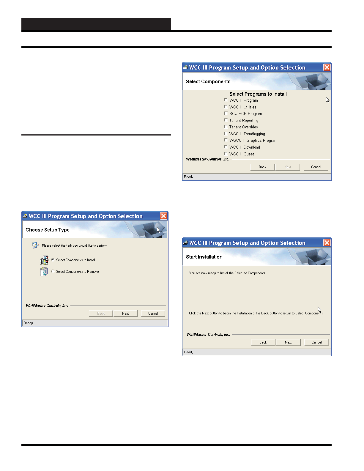
Step 2: This disk should “autorun” and start the installation
process and then display the WCC III Program Setup and Option
Selection Screen. The WCC III Program Setup and Option
Selection Screen will allow you to select the installation or removal
of the various WCC III component programs on to the WCC III
Front end computer’s hard drive.
Insert the WCC III Program Setup CD (DM1WC011-
Step 4: Using your left mouse button, select the desired check
boxes to the left of the programs you wish to install and then leftclick the
program(s) onto the WCC III Front end computer’s hard drive.
<Next> button to continue with the installation of these
Step 3: Choose either “Select Components to Install” and left-
click the <Next> button to continue with the WCC III program
installation or choose “Select Components to Remove” and left-
click the
removal process.
The <Back> button will take you back one screen and the
<Cancel> button will allow you to cancel the WCC III Program
Setup installation.
The instructions that follow describe the installation process. The
removal process closely follows the installation procedure, but
instead of installing the various WCC III component programs, it
will uninstall them.
<Next> button to continue with the WCC III program
2-2
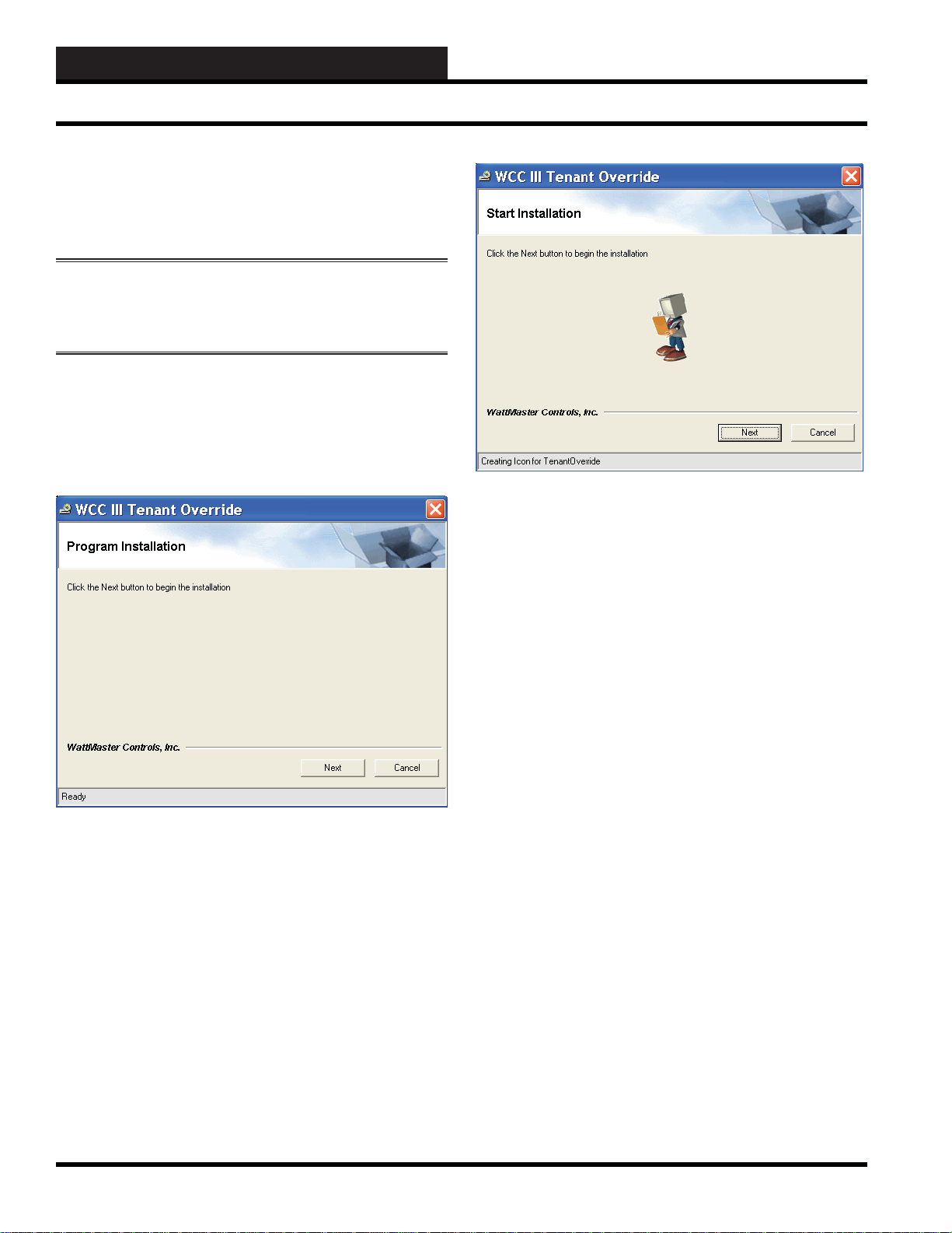
Step 5: The screen will ask you to click the <Next> button to
begin installation. After again verifying that you really want to
install these WCC III programs, please left-click the
button.
The <Back> button will take you back one screen and the
<Cancel> button will allow you to cancel the WCC III Program
Setup installation.
<Next>
WCC III Technical Guide
Page 5
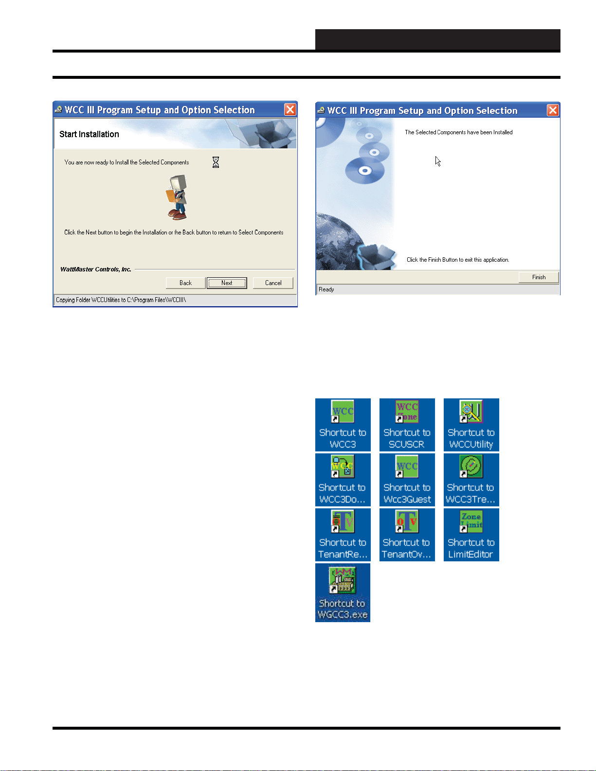
Step 6: The mouse cursor will turn to an hourglass-shaped
cursor to indicate that the WCC III installation process is still
continuing. The “Ready” fi eld at the bottom of this screen will
show the progress of the WCC III programs that were selected
for installation. (Copying various subdirectories and fi les). The
WCC III installation program will create (or copy over existing
subdirectories) the following subdirectories on the WCC III Front
end computer’s local disk C:\Program Files\WCCIII subdirectory,
depending on the selected programs to be installed:
2. INITIATING THE SYSTEM
Full WCC3 Installation
Step 7: After the installation is complete, the screen shown above
will be displayed. Please left-click the <Finish> button to exit the
WCC III program setup installation process.
These are the possible shortcut icons that should now be on your
Windows Desktop screen, depending on your WCC III program
installation selections:
C:\Programs\WCCIII\SCUSCR
C:\Programs\WCCIII\Tenant OVR
C:\Programs\WCCIII\Tenant Report
C:\Programs\WCCIII\WCC3
C:\Programs\WCCIII\WCCdownload
C:\Programs\WCCIII\WCC3Guest
C:\Programs\WCCIII\WCC Trendlogging
C:\Programs\WCCIII\WCCUtilities
C:\Programs\WCCIII\WGCC3
The
<Back> button should take you back one screen, but at this
point it is too late in the installation process to go back one screen.
The <Cancel> button should allow you to cancel the WCC III
Program Setup installation, but at this point it is too late to cancel
the installation process.
WCC III Technical Guide
2-3
Page 6
2. INITIATING THE SYSTEM
Limited WCC3 Installation
WCC III Limited Installation Software
- DM1WC012-01X
Please note: Y our user name mus t hav e
suffi cient rights to install these WCC III Limited
programs onto your computer’s hard drive.
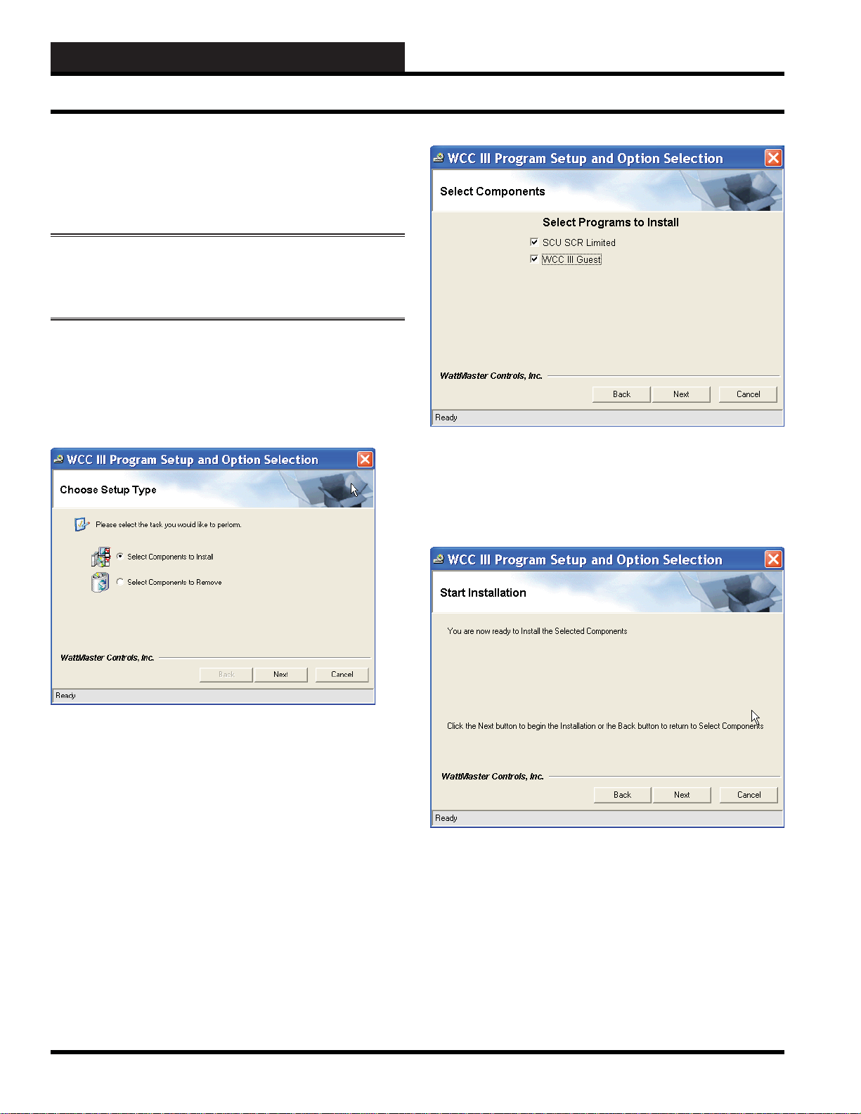
Step 1:
(DM1WC012-01X) into your computer’s CDROM/DVD drive.
Step 2: This disk should “autorun” and start the installation
process and then display the WCC III Limited Program Setup and
Option Selection Screen.
Insert the WCC III Limited Program Setup CD
The WCC III Limited Program Setup and Option Selection Scr een
will allow you to select the installation or removal of the various
WCC III component programs onto the WCC III Front end
computer’s hard drive.
Step 4: Using your left mouse button, select the desired check
boxes to the left of the programs you wish to install and then leftclick the
program(s) onto the WCC III Front end computer’s hard drive.
<Next> button to continue with the installation of these
Step 3: Choose either “Select Components to Install” and left-
click the
installation or choose “Select Components to Remove” and left-
click the <Next> button to continue with the WCC III program
removal process.
The
<Cancel> button will allow you to cancel the WCC III Program
Setup installation.
The instructions that follow describe the installation process. The
removal process closely follows the installation procedure, but
instead of installing the various WCC III component programs, it
will uninstall them.
<Next> button to continue with the WCC III program
<Back> button will take you back one screen and the
2-4
Step 5: The screen will ask you to click the <Next> button to
begin installation. After again verifying that you really want to
install these WCC III programs, please left-click the <Next>
button.
The
<Back> button will take you back one screen and the
<Cancel> button will allow you to cancel the WCC III Program
Setup installation.
WCC III Technical Guide
Page 7
2. INITIATING THE SYSTEM
Limited WCC3 Installation
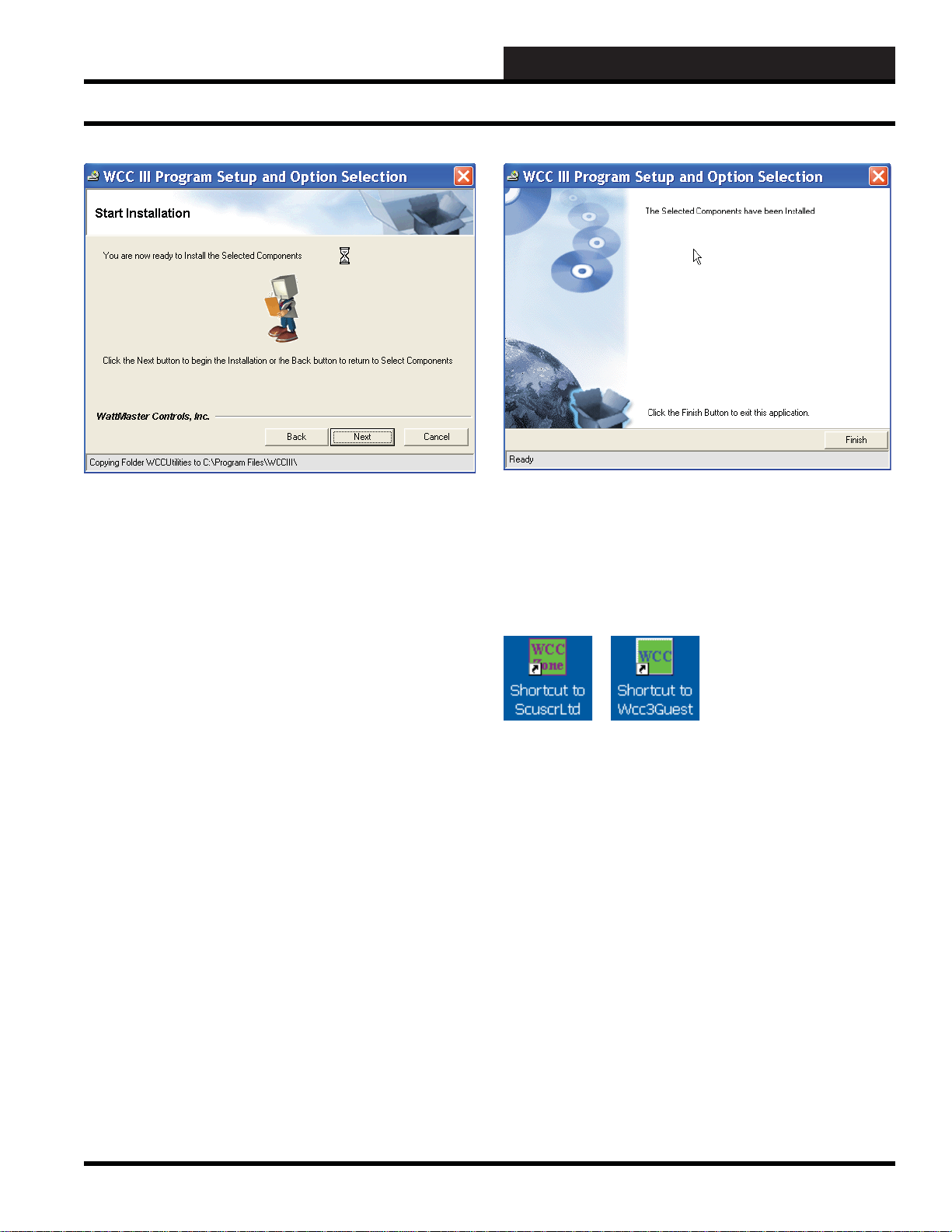
Step 6: The mouse cursor will turn to an hourglass-shaped
cursor to indicate that the WCC III installation process is still
continuing. The “Ready” fi eld at the bottom of this screen will
show the progress of the WCC III programs that were selected
for installation. (Copying various subdirectories and fi les). The
WCC III installation program will create (or copy over existing
subdirectories) the following subdirectories on the WCC III Front
end computer’s local disk C:\Program Files\WCCIII subdirectory,
depending on the selected programs to be installed:
C:\Program Files\WCCIII\SCUSCR Ltd
C:\Program Files\WCCIII\WCC3Guest
The
<Back> button will take you back one screen, but at this point
it is too late in the installation process to go back one screen.
The <Cancel> button will allow you to cancel the WCC III
Program Setup installation, but at this point it is too late to cancel
the installation process.
Step 7: After the installation is complete, the screen shown above
will be displayed. Please left-click the <Finish> button to exit the
WCC III program setup installation process.
These are the two possible shortcut icons that should now be
on your Windows Desktop screen, depending on your WCC III
program installation selections:
WCC III Technical Guide
2-5
Page 8
2. INITIATING THE SYSTEM
WCC III T enant Override Installation
WCC III T enant Override Installation
Software - DM1WC013-01X
Please note: Y our user name mus t hav e
suffi cient rights to install these WCC III Limited
programs onto your computer’s hard drive.
Step 1:
(DM1WC013-01X) into your computer’s CDROM/DVD drive.
Step 2: This disk should “autorun” and start the installation
process and then display the WCC III Tenant Override Program
Installation Screen.
Insert the WCC III Tenant Override Program Setup CD
Step 4: The mouse cursor will turn to an hourglass-shaped cursor
to indicate that the WCC III Tenant Override installation process is
still continuing. The “Ready” fi eld at the bottom of this screen will
show the progress of the WCC III Tenant Override program that was
selected for installation. The WCC III Tenant Override installation
program will create (or copy over existing subdirectories) the
following subdirectory on the end user customer computer’s local
disk: C:\Program Files\WCCIII\TenantOverride.
The
<Cancel> button should allow you to cancel the WCC III
Program Setup installation, but at this point it is too late to cancel
the installation process.
The WCC III Tenant Override Program Installation Screen will
allow you to install the WCC III Tenant Override programs onto
the end user customer’s computer hard drive.
Step 3: Please left-click the <Next> button to continue with
the program installation. The
cancel the WCC III Tenant Override program installation.
<Cancel> button will allow you to
2-6
WCC III Technical Guide
Page 9

Step 5: After the installation is complete, the screen shown above
will be displayed. Please left-click the
WCC III Tenant Override program installation process.
<Finish> button to exit the
2. INITIATING THE SYSTEM
WCC III T enant Override Installation
There should now be a Tenant Override shortcut icon on your
Windows Desktop screen.
WCC III Technical Guide
2-7
Page 10
2. INITIATING THE SYSTEM
Running the WCC3 Program
How to Start or Run the WCC3.exe
Program (SS5021)
The WCC3.exe shortcut icon should have been
installed on your WCC III Front end computer
desktop with the WCC III Installation Software
CD.
The WCC III Installation Software CD is
WattMaster Controls Part # DM1WC011-01X.
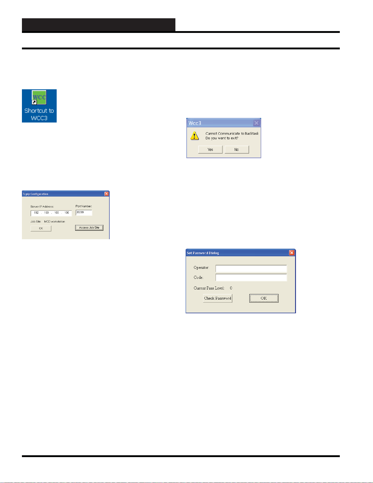
To start the WCC3.exe program, double-click the left mouse button
the Shortcut Icon on the Windows desktop.
After a short period of time, dependent upon the CPU speed of your
Windows based computer and the speed of your IP connection to
the internet, the WCC III T ype Connection Dialog Box will appear.
By selecting
connect to the selected WCC III – MCD via this selected IP address
connection. It should bring up the WCC III Set Password Dialog
screen within a new window. If the IP address connection fails to
connect to the WCC III – MCD, then another small dialog box
window will appear. This is the Cannot Communicate to Backtask
Dialog Box.
If you click <Yes>, you will exit the WCC3.exe program. You will
have to fi gure out why you cannot connect to the WCC III – MCD
via the IP address connection.
If you click
but instead you will be connected to the WCC III Main Menu.
This connection to the WCC III Main Menu is not an actual IP
connection, but rather a “dummy” WCC III main menu screen
window with no values. This “dummy” WCC III main menu
screen window will allow you to view and see what the actual
WCC3.exe screens will look like – minus any data.
<OK>, the WCC3.exe program will now start to
<No>, you will not exit the WCC3.exe program,
Server IP Address:
This is the static IP address of the WCC III – MCD. An IP Address
is like a phone number on the world wide web. The IP address for
the WCC III – MCD must be Static (does not change) as opposed
to Dynamic (constantly changing). This static IP address must be
provided by your internet service provider. (A static IP address
is the preferred IP connection method for the WCC III system to
function.) If you actually know the static IP address of the WCC III
– MCD that you wish to connect to, please enter it here in the Server
IP Address fi eld, or better yet, continue to the Remote Access Dialog
Window by selecting the
You can use a Dynamic IP Address with the WCC III – MCD,
but you must then have what is called a static “Host Name”. This
static “Host name” must then be provided by your internet service
provider and is limited to 58 total characters.
Port Number:
The WCC3.exe program opens a two-way, secure communications
port that then allows for communication between WCC III – MCD
and the WCC3.exe program that is running on the WCC III Front
end computer. This IP Address connection is done on a higher
address port number than normal (WCC III connection is port
number 39289) to help reduce the risk of computer hacking.
Using your mouse, please left-click on the
button. The Remote Access Dialog Window will appear.
<Access Job Site> button.
<Access Job Site>
In the Set Password Dialog Screen enter an “Operator:”
identifi cation and a “Code:” or password equal to at least a pass
level 0 that has been previously set up on the WCCIII System
Parameter – Operator Code Screen. (See the Operator Code
Screen of the System Parameter Scr een in Section 3 for information
on setting up Operator Codes) Click
“Current Pass Level:” stays at 0 or higher (1, 2, or 3) then click
<OK>. By selecting <OK>, the WCC3.exe program will now start
to connect to the selected WCC III – MCD via this selected IP
address connection. It should bring up the WCC III Main Menu
within a new window. If the “Current Pass Level:” changes to
–1 then you do not have access to the WCCIII – MCD. If you
do not have access to the WCCIII – MCD and you click
then this connection to the WCC III Main Menu is not an actual IP
connection, but rather a “dummy” WCC III Main Menu window
with no values. This “dummy” WCC III Main Menu window will
allow you to view and see what the actual WCC3.exe screens will
look like – minus any data.
<Check Password>, if the
<OK>
2-8
WCC III Technical Guide
Page 11
2. INITIATING THE SYSTEM
Running the WCC3 Program
computers. This reused JobSite.dat will then recreate the needed
“Job Site” subdirectories on the other WCC III front end computers
upon the reselection of the Job Site IP address.
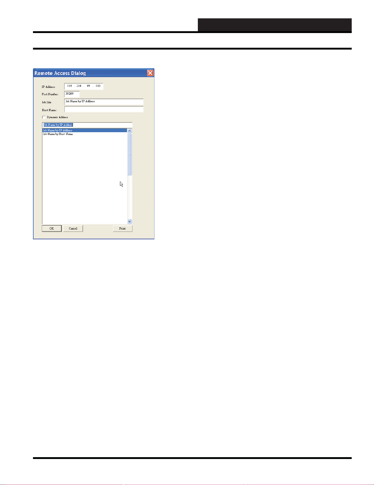
In an already fi lled out Remote Access Dialog Box, you can simply
select from the list of previously entered Job Sites that are displayed
in the bottom box fi eld. Then left-click
back to the Connection Dialog Box that was fi rst displayed. This
Connection Dialog Box now should have the desired IP address in
the Server IP Address location fi eld and the port number (39289)
in the Port Number location fi eld for the WCC III – MCD that you
wish to connect to with the WCC3.exe program.
IP Address:
This is the static IP address where the WCC III – MCD is located.
An IP Address is like a phone number on the world wide web.
The IP address for the WCC III – MCD must be static (does not
change) as opposed to Dynamic (constantly changing). This static
IP Address must be provided by your internet service provider.
(A static IP address is the preferred IP connection method for the
WCC III system to function.)
<OK>. This will take you
The Remote Access Dialog Box will allow you to enter multiple
WCC III – MCD IP addresses based upon “Job Site” names. This
is done by typing in the name of the jobsite you wish to call your
system.
First you must select a “BLANK” line in the bottom box area
with your left mouse button. (This line will then be highlighted
in “Blue”) You must then enter a Job Site name in the “Job Site”
fi eld, along with the static IP address and Port number (39289) for
the WCC III – MCD that you wish to connect to with the WCC3.
exe program.
If you are using a static “Host Name” instead of a static IP address
please make sure that the Dynamic Address check box has been
selected, along with the static “Host Name” in the space provided.
As mentioned previously, you must get this static “Host Name”
from your internet service provider, and it is limited to 58 characters
total.
Please note that this “Job Site” name will also be the name of a
subdirectory that will automatically be created in the Local disk C:\
Programs\WCCIII\WCC3 subdirectory on the WCC III Front end
computer. The Remote Access Dialog Box also creates a JobSite.
dat data fi le in the C:\ProgramFiles\WCCIII\WCC3 subdirectory.
This data fi le is not a viewable type of fi le. The JobSite.dat fi le
can be copied and then can be used on other WCC III front end
Port Number:
The WCC3.exe program opens a two-way, secure communications
port that then allows for communication between WCC III – MCD
and the WCC3.exe program that is running on the WCC III front
end computer. This IP Address connection is done on a higher
address port number than normal (WCC III connection is port
number 39289) to help reduce the risk of computer hacking.
Job Site:
This is the name of the jobsite you wish to call your system. Please
note that this name will also be the name of a subdirectory that
will automatically be created in the Local disk C:\ProgramFiles\
WCCIII\WCC3 subdirectory.
Host Name:
You can use a Dynamic IP Address with the WCC III – MCD,
but you must then have what is called a static “Host Name”. This
static “Host name” must then be provided by your internet service
provider and is limited to 58 total characters.
When you have fi lled out all necessary fi elds, left-click
This will take you back to the Connection Dialog Box that was
fi rst displayed. This Connection Dialog Box now should have the
desired IP address in the Server IP Address location fi eld and the
port number (39289) in the Port Number location fi eld for the
WCC III – MCD that you wish to connect to with the WCC3.exe
program.
<OK>.
WCC III Technical Guide
2-9
Page 12

2. INITIATING THE SYSTEM
Running the WCC3 Program
Left-click <Cancel> to return to the Connection Dialog Box that
was fi rst displayed. The Connection Dialog Box will have the
same IP address as listed originally before in the Server IP Address
location fi eld and the port number (39289) in the Port Number
location fi eld.
Left-click
Dialog Box to your Windows system default printer on the WCC
III front end computer. This print function is provided to give you
a hard paper backup copy of these IP address for the various WCC
III – MCD that you may have. This print function also creates a
Printscreen.dat data fi le in the C:\ProgramFiles\WCCIII\WCC3
subdirectory. This data fi le is not a viewable type of fi le.
<Print> to send all of this data in this Remote Access
2-10
WCC III Technical Guide
Page 13

2. INITIATING THE SYSTEM
Setting Passcodes
Assigning Operator Access Codes
Access codes can be assigned for up to 16 operators with 4 levels
of access. The systems are sent from the factory with an operator
number of 33333 and an access number of 3333. To assign other
codes, follow the steps in this section.
Step 1: With the WCC III Main Menu showing on the
screen, place the cursor on “System Parameters” and press
<Enter> to access the System Parameter Screen. The System
Parameter Screen should come into view with the computer
awaiting the operator ID.
Step 2: Input the factory set identifi cation number of 33333
and press <Enter>. The numbers at the top of the keyboard
must be used. The cursor will automatically move to the right
and await the code ID.
Step 3: Input the factory set code number of 3333 and press
<Enter>. The message to the right of the cursor should change
from “
View Screen Only” to “View All Codes.”
Step 4: Use the right arrow key to move the cursor to the
right of the “View All Codes” message.
NOTE: To access the system, the password codes must be
entered exactly as they were entered on this screen, including
any spaces which were entered using the space bar.
Passw ord Entry
To be able to make any changes to the inputs in the system, you
must have a password which has either a level 1, level 2 or level
3 access assigned to it. You enter your password by following the
steps in this section.
Step 1: With the Main Menu showing on the screen, place
the cursor on “System Parameters” and press <Enter> to
access the System Parameter Screen. The System Parameter
Screen should come into view with the computer awaiting the
operator ID.
Step 2: Input your assigned operator code and press
<Enter>. The cursor will automatically move to the right and
await the code ID.
Step 5: Press <Enter> and the screen will appear which
will allow codes for 16 operators with 4 levels of access. The
descriptions of the access levels are listed at the bottom of this
screen.
Step 6: Access codes can be assigned for the operators
who will be using the system. The operator ID can be up to
16 characters but is generally 5 characters using any letters,
numbers, or symbols. The code ID can be up to 10 characters
but is generally 4 characters using any letters, numbers, or
symbols. The system will distinguish between small and
capital letters. To assign an operator ID, type the desired
characters and press
<Enter>. The cursor will automatically
move to the right and await the code ID. Type the desired code
ID and press <Enter>. The cursor will now automatically
move to the right and await the Level access number. Type in
this Level number (1 through 3, 1 being the lowest and 3 being
the highest) and press
Step 7: After the codes have been entered, make sure you
<Enter>.
know what the codes are before leaving this screen. We
recommend leaving the 33333, 3333 access code until the
other codes are tested. To leave this screen, press
<HOME>
twice to return to the System Parameter Screen. Press
<HOME> once more to return to the Main Menu.
Step 3: Input your assigned code ID and press <Enter> You
are now “signed on” and may enter and/or change data as
necessary.
NOTE: You must enter your exact password. The system
distinguishes between upper and lower case letters, and it
recognizes spaces which are created using the
<space bar> .
WCC III Technical Guide
2-11
Page 14
2. INITIATING THE SYSTEM
WCCIII - MCD Local 2 by 20 Line Display
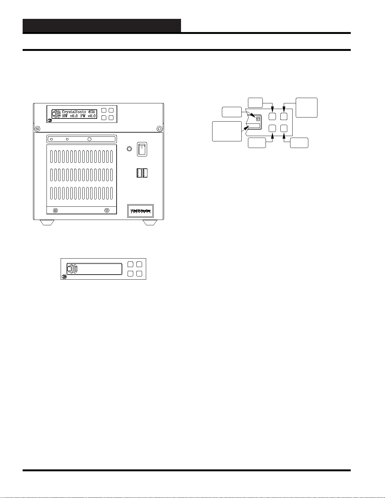
WCC III - MCD Display
WCC III - MCD Front View
Crystalfontz
POWER H.D.D RESET
Crystalfontz 631
HW v2.0 FW v2.0
Crystalfontz
HeartBeat
Location
Button Message
Area
| Hold
| Rotate
"UP"
Button
"DOWN"
Button
"SELECT"
"HOLD"
"ROTATE"
Button
"MENU"
Button
The LCD Display Buttons
There are four buttons on the front of the LCD display on the WCC
III - MCD.
The Upper Left button is the “UP” menu navigation button.
The Lower Left button is the “DOWN” menu navigation button.
The Upper Right button works as a “SELECT” button under the
MENU option or else it operates as a “HOLD” or “ROTATE”
button for the information screens.
The WCC III – MCD now has a 2 line by 20 character dot matrix
liquid crystal display. This LCD displays the following information:
IP ADDRESS, MCD UPTIME, RX, TX, Down, Up, User %,
System %, Nice %, Idle %.
This display is very helpful to determine if the WCC III – MCD is
functioning correctly.
2-12
Also the “BUTTON MESSAGE” area will momentarily display
either “HOLD” or “ROTATE” when the Upper Right button is
depressed.
The Lower Right button is the “MENU” button. It also serves as
a “HOME” button to return to the main menu when in any of the
sub-menus.
WCC III Technical Guide
Page 15

2. INITIATING THE SYSTEM
WCCIII - MCD Local 2 by 20 Line Display
SELECT
CHECK
DESELECT
HEART BEAT
UP/DOWN ITEM SELECT
SUBMENU UP SELECT
SUBMENU DOWN SELECT
The LCD Character Boxes
The Select box, Check box, and Deselect-box icons are displayed
on the LCD as a visual aid to selecting or deselecting an item.
The difference between the Select box and the Check box is that
the Select box icon is the default setting and the Check box icon is
a change to the setpoint that the user has initiated.
The Deselect box turns the selected item “OFF”.
The Heart Beat icon is to be used as a watchdog to make sure that
this Linux-based LCD program is still running and is not “Locked
Up”.
The Up/Down Item Select icon is used to display which of the
currently selected menu items is currently selected for viewing
and/or change.
WCC III MCD IPADDRESS
XXX.XXX.XXX.XXX
Crystalfontz
WCC III - MCD IP Address
This screen shows the actual IP address of the WCC III – MCD.
An Internet Protocol (IP) address is a numerical identifi cation
and logical address that is assigned to the WCC III – MCD that is
participating in a computer network that is then utilizing the Internet
Protocol for communication between its nodes. The WCC III MCD is confi gured to use the same IP address each time it powers
up - this is known as a Static IP address. In contrast, in situations
when the other computer’s IP address is assigned automatically,
it is known as a Dynamic IP address. The Static IP addresses are
manually assigned to the WCC III - MCD by an administrator.
MCD UPTIME
D.Days H.Hours m.Min
Crystalfontz
The submenu Up/Down icons are a reminder to use the Upper Left
or Lower Left buttons (UP/DOWN) to affect the changes to the
user-desired “Adjustable” settings and are used for “CONTRAST”,
“ON BRIGHTNESS”, and “OFF BRIGHTNESS” adjustments.
MCD UPTIME
D - Days, H - Hours, m - Min
This is the displayed run time total since the last reset or startup
of the WCC III – MCD. It is often used as a measure of computer
operating system reliability and stability, in that this time represents
the time that a computer can be left unattended without crashing
or needing to be rebooted for any administrative or maintenance
purposes.
WCC III Technical Guide
2-13
Page 16
2. INITIATING THE SYSTEM
WCCIII - MCD Local 2 by 20 Line Display
Rx: 0.0 Down l
Tx: 0.0 UP 0
Crystalfontz
IP Packet
An IP packet is the formatted unit of data that is carried by a
packet mode computer network. When the data is formatted into
IP packets, the bit rate of the communication medium (Ethernet)
can better be shared among users than if the network were circuit
switched.
Rx: Displays the number of IP Packets that are currently being
received on the network card right now.
Tx: Displays the number of IP Packets that are currently being
transmitted on the network card right now.
Down: Total IP Packets that have been received on the network
card since the last bootup.
Up: Total IP Packets that have been transmitted on the network
card since the last bootup.
Nice becomes useful when there are several processes that are
demanding more resources than the WCC III – MCD CPU can
provide. In this state, a higher priority process will get a larger
chunk of the WCC III – MCD CPU time than a lower priority
process. If the WCC III – MCD CPU can deliver more resources
than the processes are requesting, then even the lowest priority
process can get up to 99% of the WCC III - MCD CPU. Only the
superuser (root) may set the niceness to a smaller (higher priority)
value. On Linux it is possible to change ”/etc/security/limits.conf “
to allow other users or groups to set a low nice value.
Idle: Percentage of the WCC III – MCD CPU’s time that the CPU
were idle and the system did not do an outstanding disk I/O request.
A computer processor is described as idle when it is not being used
by any program.
Programs which make little use of the CPU Idle Time mean that
they run at a low priority so as not to impact programs that run at
normal priority like BackTask.exe. Many programs that use the
WCC III – MCD CPU idle time can cause the WCC III - MCD CPU
to always be 100% utilized, so that the time spent where the WCC
III – MCD CPU would have been idle is instead spent performing
useful computations. This generally causes the WCC III – MCD
CPU to consume more power as most modern computer’s CPUs
can enter power-save modes when they are idle.
Usr: 0.0% Nice 0.0%
Sys: 0.0% Idle100.0%
Crystalfontz
CPU Usage Percentages
Usr: Percentage of the WCC III – MCD CPU’s utilization that
occurred while executing at the user level (application). BackTask.
exe is an application.
Sys: Percentage of the WCC III – MCD CPU’s utilization that
occurred while executing at the system level (kernel). The Linux
operating system is system level.
Nice: Percentage of the WCC III – MCD CPU’s utilization that
occurred while executing at the user level.
Nice (pronounced /na is/) is a program that’s found within Linux.
Nice directly maps to a kernel call of the same name. For any
given process, it changes the priority in the kernel’s scheduler. A
niceness of −20 is the highest priority and 19 is the lowest priority.
The default niceness for any process is inherited from its parent
process, usually 0.
LCDproc Menu
Options
Crystalfontz
Options Menu
Press the Lower Right button (MENU) to select the “LCDproc
Menu” selection.
Press the Upper Right button (SELECT) to select the “Option”
selection.
2-14
WCC III Technical Guide
Page 17
2. INITIATING THE SYSTEM
WCCIII - MCD Local 2 by 20 Line Display
OPTIONS
Heartbeat
Crystalfontz
Options Menu – Heart Beat Selection
Press either the Upper Left or Lower Left buttons (UP/DOWN)
to select the following user settable options: “Heart Beat”,
“Backlight”, or “CFontzPacket”.
Press the Upper Right button (SELECT) to select or toggle the
“Heartbeat” selection setting ON or OFF with either the X box,
Check box or No box icon.
Or press the Lower Left button (DOWN) to select the “Backlight”
selection.
Or press the Lower Left button (DOWN) twice to select the
“CFontzPacket” selection.
Heartbeat
Backlight
Crystalfontz
Options Menu – Backlight Selection
Press the Upper Right button (SELECT) to select or toggle the
“Backlight” selection setting ON or OFF with either the X box,
Check box or No box icon.
Heartbeat
CFontxPacket
Crystalfontz
Options Menu – CfontzPack et Submenu
Press either the Upper Left or Lower Left buttons (UP/DOWN)
to select the following user settable options: “Contrast”, “On
Brightness”, or “Off Brightness”.
Or press the Upper Left button (UP) to select the “HEART BEAT”
selection.
Or press the Upper Left button (UP) twice to select the
“BACKLIGHT” selection.
CFontzPacket
Contrast
Crystalfontz
Options Menu – CfontzPack et Submenu – Contrast
Selection
Press the Upper Right button (SELECT) to select the “Contrast”
selection setting.
Or press the Upper Left button (UP) to select the “Heartbeat”
selection.
Or press the Lower Left button (DOWN) to select the
“CFontzPacket” selection.
WCC III Technical Guide
Contrast
min max
Crystalfontz
Options Menu – CfontzPack et Submenu – Contrast
Selection – Contrast Setting
Press either the Upper Left or Lower Left buttons (UP/DOWN) to
affect the change to the user desired “Contrast” setting.
2-15
Page 18

2. INITIATING THE SYSTEM
WCCIII - MCD Local 2 by 20 Line Display
Contrast
On Brightness
Crystalfontz
Options Menu – CfontzPack et Submenu – On
Brightness Selection
Press the Upper Right button (SELECT) to select the “On
Brightness” selection setting.
On Brightness
min max
Crystalfontz
Options Menu – CfontzPack et Submenu – On
Brightness Selection – On Brightness Setting
Press either the Upper Left or Lower Left buttons (UP/DOWN) to
affect the change to the user desired “On Brightness” setting.
On Brightness
Off Brightness
Crystalfontz
Options Menu – CfontzPack et Submenu – Off
Brightness Selection
Press the Upper Right button (SELECT) to select the “Off
Brightness” selection setting.
Off Brightness
min max
Crystalfontz
Options Menu – CfontzPack et Submenu – Off
Brightness Selection – Off Brightness Setting
Press either the Upper Left or Lower Left buttons (UP/DOWN) to
affect the change to the user desired “Off Brightness” setting.
2-16
WCC III Technical Guide
Page 19

2. INITIATING THE SYSTEM
The WCC III - MCD
The WCC III – MCD
Overview
The WCC III – MCD was converted from the Windows XP
operating system over to the Ubuntu version of Linux using the
command line interface only and was then released by WattMaster
Controls in October of 2009. The main function of the WCC
III – MCD is to provide a hardware and software platform for a
program that WattMaster Controls has developed that is called
“BACKTASK.exe”. The BACKTASK.exe program is a multiple
BACKground TASKing application program.
BACKTASK.EXE (SS5009)
The BACKTASK.exe program performs many functions such
as:
• USB communications to the internal MCOMM board
• Time clock functions
• Analog/binary global processing
• Overrides of control points
• Holiday scheduling
• Optimal starts
• PID programs
• Shed /Restore programs
• Duty cycle programs
• Proportional Programs
• Tenant Overrides
• Emailing of alarms
The BACKTASK.exe program also provides for remote IP
connection to a set of windows-based programs generally referred
to as the WCC III programs. This WCC III – MCD also has
hardware (WCCIII MCOMM board) that interfaces to a RS-485
communications loop that connects to SAT III type controllers for
building automation controls.
be plugged into a (NON – UPS) 120VAC outlet. The power cord
for the WCC III – MCD is to be connected to a dedicated UPS
(Uninterruptible Power Supply) outlet so that the MCD will keep
running during a minor power outage. The Cable/DSL modem/
router should also be plugged into one of these dedicated UPS
(Uninterruptible Power Supply) outlets.
MCD-Menu Program Overview
WattMaster Controls has developed a simple setup installation
program for the Linux command line interface, and this program
is called mcd-menu. Prior knowledge of Linux is not required, but
would be helpful. This mcd-menu program has eleven subprograms
incorporated into it that will allow for the following operations to
be preformed:
• The setup of the Network IP Confi guration of the
WCC III – MCD network card interface
• Copying of the BackTask specifi c data fi les to the root
of the USB Drive
• Restoring of the BackTask specifi c data fi les from the
root of the USB Drive
• The resetting of the WCC III - MCD IP address back
to the WattMaster factory Default IP Address settings
• The resetting of the WCC III - MCD DNS settings
back to the WattMaster factory default DNS settings
• The restarting of the 2 by 20 line LCD Driver that is
located on the front of the WCC III - MCD
• The restarting of the 2 by 20 line LCD Display that is
located on the front of the WCC III - MCD
• The testing of the Internet Connection, from the WCC
III - MCD to the internet
• The testing of DNS Settings, from the WCCIII - MCD
to the internet
• The shutdown of the WCC III - MCD – properly
closing down
• The shutdown and restart of the WCC III - MCD
Watchdog Circuit/P ow er F ail
If the BACKTASK.exe program is not running on the WCCIII
- MCD, there is a watchdog circuit that will restart the WCCIII
– MCD. This watchdog circuit may interfere with the installation
of new BACKTASK.exe software. There is a way to disable this
watchdog circuit. Please contact WattMaster Controls for further
information on temporarily disabling this watchdog circuit. In
addition to this watchdog circuit, there is a small wall wart 24vac
transformer that must be connected to 120VAC or else the WCCIII
- MCD will restart every two minutes. This is part of the power fail
design circuit of the WCC III – MCD. This transformer is meant to
WCC III Technical Guide
The Webmin access method can also accomplish all of these same
tasks, but is a little bit harder to use and is meant to be more of an
“off site” management tool for the WCC III - MCD. The mcdmenu program is meant to be used as the initial IP setting tool and
BACKTASK data fi le loading tool for the WCC III - MCD. For
this a monitor and keyboard needs to be connected temporarily
just for the initial IP setup and BACKTASK data fi le loading.
2-17
Page 20

2. INITIATING THE SYSTEM
Using the MCD-Menu Program
Using the MCD-Menu Program
Overview
The default administration username is wcciii and the password is
wt@@58 This user name and password are both CAP sensitive,
and should be entered in lower case letters only.
1. Type “mcd-menu” at the wcciii@wcciii-mcd:~$ prompt (view
only – restricted access). You can perform very few functions
as “View only restricted access”, such as Copy/restore WCCIII
data fi les.
2.To do the root level tasks like confi gure IP address,
shutdown the WCC III - MCD, reboot the WCC III - MCD,
reset the WCC III – MCD IP addresses and DNS settings
to DEFAULT confi gurations, and of course, copy/restore
WCCIII data fi les, you must be signed in as a “root” user.
You must be very careful signed in as a root user because
you can render your WCC III - MCD system unable to
communicate with the outside world if improperly used.
If you have selected a command and you are not signed in as a
root user, it will give you a warning message as listed below:
**************************************************
* *
* Warning: The program is not running as root. *
* Interface confi gurations or saving may fail! *
* *
**************************************************
The mcd-menu is straight forward. You can select the desired
function by number (1 to 11) and hit the enter key to execute
the desire function. You can quit this mcd-menu program at any
time by hitting the “q” and then the enter key to quit. Then type
“exit” at the wcciii-mcd:~$ prompt.
NOTE: DO NOT run the mcd-menu program from inside
WebMin’s Command Shell. It will not work there. This mcdmenu program is meant to work only from the telnet/ssh
session or from the actual console (i.e. keyboard and monitor
that is connected to the WCC III - MCD).
Running the mcd-menu program
Step 1:
and the password is wt@@58. Type mcd-menu at the prompt
(view only – restricted access)
Step 2: The following fi rst main menu screen should appear:
Please Pick a Function:
1. Setup Network Confi guration
2. Copy BackTask Files to USB Drive
3. Restore BackTask Files from USB Drive
4. Reset MCD to Default IP Address
5. Reset MCD to Default DNS Settings
6. Restart LCD Driver
7. Restart LCD Display
8. Test Internet Connection
9. Test DNS Settings
10. Shutdown MCD
11 Total Choices
Press ENTER (or “d”) to scroll downward
OR “u” to scroll upward (Press “q” to quit)
PLEASE ENTER A CHOICE: ___
Using the default low level, the username is wcciii
Helpful hint: While at the wcciii@wcciii-mcd:~$ prompt you
can select/toggle through previously entered commands with
the “UP” arrow key.
The new fi les are rolled into the installation fi les so they will
be available on new systems. They can also be pushed or
updated to older systems via secure ftp and then run from the
shell. Alternatively, they can also be upload to the WCC III
– MCD from inside the WebMin program and then run from
the command line from within the browser. This mcd-menu
program may be run remotely from PuTTY which is a terminal
emulator application program, provided that this program is
installed and properly setup on your computer.
2-18
WCC III Technical Guide
Page 21

2. INITIATING THE SYSTEM
Using the MCD-Menu Program
Step 3: Pressing the “enter” key or the “d” key will result
in the next (second) menu screen appearing. The following
second main menu screen should appear:
Please Pick a Function:
11. Shutdown and Reboot MCD
11 Total Choices
Press ENTER (or “d”) to scroll downward
OR “u” to scroll upward (Press “q” to quit)
PLEASE ENTER A CHOICE: ___
Helpful hint: You do not have to use the “u” or “d” keys and then
the “enter” to toggle between the fi rst and second menus. By using
the just “enter” key you can toggle between the fi rst menu screen
with selections of 1 to 10 and the second menu screen that has
selection 11 only.
Setup Network Confi guration (Choice #1)
This sub program will allow you to set the IP confi guration of the
WCC III – MCD. You will be prompted to enter a IP Address in
the XXX.XXX.XXX.XXX format. If you do not have all of the
following information, then you should not proceed any further.
The values should be written below for future reference.
Static IP address ___ ___ ___ . ___ ___ ___ . ___ ___
___ . ___ ___ ___ Must be static.
You will be now be prompted to enter the following data, and if you
do not want to change the address listed within the listed brackets
[ ] then just press the enter key and the value in the brackets [ ]
will not change.
Enter interface confi guration data:
Interface to confi gure: [eth0] __
IP address: [192.168.100.100] __
Netmask: [255.255.255.0] __
Gateway (none for no gateway): [192.168.100.1] __
Nameservers (blank separate list):
[208.67.222.222_208.67.220.220] __
Interface to confi gure: [eth0] __ There are two possible
entries here “eth0” and “eth0:0”
eth0 is the default main IP address for the WCC III – MCD.
eth0:0 is the secondary IP address for the WCC III – MCD and
it is meant for direct connection from the WCC III – MCD to a
local computer (Laptop) via a Ethernet crossover cable.
IP address: [192.168.100.100] __ This IP address must be
supplied by your internet provider or by your network IT
personnel. It must be a “static” as in not changing.
Netmask: [255.255.255.0] __ This IP address must be
supplied by your internet provider or by your network IT
personnel.
Gateway (none for no gateway): [192.168.100.1] __ This IP
address must be supplied by your internet provider or by your
network IT personnel.
Subnet mask ___ ___ ___ . ___ ___ ___ . ___ ___
___ . ___ ___ ___
Gateway ___ ___ ___ . ___ ___ ___ . ___ ___ ___ .
___ ___ ___
Nameserver ___ ___ ___ . ___ ___ ___ . ___ ___ ___
. ___ ___ ___
Nameserver ___ ___ ___ . ___ ___ ___ . ___ ___ ___
. ___ ___ ___ Optional
Nameserver ___ ___ ___ . ___ ___ ___ . ___ ___ ___
. ___ ___ ___ Optional
WCC III Technical Guide
Nameservers (blank separate list):
[208.67.222.222_208.67.220.220] __
address for a DNS server.
Some internet service providers do not have a static IP
address. They use what is called static host names, which
correspond to a actual static IP address. You can enter more
than one IP address here, a primary and a secondary,
and please note that they must be separated by a space.
For example, on the Internet there exists a special case of
nameservers lookup sites, the so called Domain Name System
(DNS) servers, which are used to translate a static hostname or
a domain name (for example, ‘WCC-CONTROLS.com’) to its
corresponding binary identifi er (the IP address 76.12.37.232),
or vice versa.
This is the actual IP
2-19
Page 22

2. INITIATING THE SYSTEM
Using the MCD-Menu Program
After you have entered in all of the required IP addresses, subnet
masks, Gateways, and/or Nameservers, the program will now
change the internal IP network confi guration fi les within the
Linux operating system of the WCC III – MCD. It will take a
few seconds to do this function, and will display the following
messages:
Confi guring interface:
/sbin/ifconfi g eth0 192.168.100.100 netmask 255.255.255.0
broadcast 192.168.100.255
Deleting old interface route:
/sbin/route del -net 192.168.100.100 netmask 255.255.255.0
eth0
Setting interface route:
/sbin/route add -net 192.168.100.0 netmask 255.255.255.0
eth0
Deleting old default route:
/sbin/route del default
Setting default route:
/sbin/route add default gw 192.168.100.1
Copy BackT ask da ta Files to USB Drive (Choice #2)
This sub program will copy all of the useful WCC III data fi les to
a USB drive (User / Contractor provided), assuming that there is a
USB drive plugged into the USB port on the WCC III – MCD. It
will copy all of these fi les to the root of the USB drive.
If there is not a USB hard drive in the USB port on the front of the
WCCIII – MCD, this program assumes that there is a USB drive
there even if it is not there. It will not report that there is a drive
reading or writing error or any other errors. So when backing up,
make sure that there is a USB hard drive in the USB socket port on
the front of the WCCIII – MCD, and also there should be a LED
on this USB hard drive that should light up when data is written or
read from it. Please verify that this LED operates when backing up
data to this USB hard drive.
All WCC III jobsites have multiple specifi c custom data fi les that
are the responsibility of the end user and/or mechanical contractor.
Any loss or the retention of these jobsite specifi c custom data fi les
are not within WattMaster Controls Inc. liabilities.
The following will be displayed on the screen:
Selecting Copy BackTask Files to USB Drive.
Writing /etc/network/interfaces:
Writing /etc/resolv.conf:
When completed the following information will be displayed:
New netstat settings:
192.168.100.100 0.0.0.0 255.255.255.0 U 0 0 0 eth0
192.168.200.0 0.0.0.0 255.255.255.0 U 0 0 0 eth0
0.0.0.0 192.168.100.1 0.0.0.0 UG 0 0 0 eth0
Network Confi guration Done.
**************************************************
* Exiting Program. *
**************************************************
wcciii@wcciii-mcd:~$
The mcd-menu program, as part of the setup process for the
IP connections, has on purpose exited the mcd-menu program.
This is normal operation.
Copying fi le: /home/wcciii/.wine/drive_c/Backtask/
AlarmBits.dat
Copying fi le: /home/wcciii/.wine/drive_c/Backtask/
AlarmMessage.dat
Copying fi le: /home/wcciii/.wine/drive_c/Backtask/
DutyCycleSchedule.dat
Copying fi le: /home/wcciii/.wine/drive_c/Backtask/
EnergyConsumption.dat
Copying fi le: /home/wcciii/.wine/drive_c/Backtask/
GeneralMessage.dat
Copying fi le: /home/wcciii/.wine/drive_c/Backtask/
GlobalAnalog.dat
Copying fi le: /home/wcciii/.wine/drive_c/Backtask/
GlobalBinary.dat
Copying fi le: /home/wcciii/.wine/drive_c/Backtask/
HolidaySchedule.dat
Copying fi le: /home/wcciii/.wine/drive_c/Backtask/
LookUpTable.dat
Copying fi le: /home/wcciii/.wine/drive_c/Backtask/
NetworkInformation.dat
Copying fi le: /home/wcciii/.wine/drive_c/Backtask/
OperatorCode.dat
Copying fi le: /home/wcciii/.wine/drive_c/Backtask/
OptimalSchedule.dat
Copying fi le: /home/wcciii/.wine/drive_c/Backtask/
OverrideSchedule.dat
Copying fi le: /home/wcciii/.wine/drive_c/Backtask/
PidProgram.dat
2-20
WCC III Technical Guide
Page 23

2. INITIATING THE SYSTEM
Using the MCD-Menu Program
Copying fi le: /home/wcciii/.wine/drive_c/Backtask/
ProportionalReset.dat
Copying fi le: /home/wcciii/.wine/drive_c/Backtask/
ShedRestoreSchedule.dat
Copying fi le: /home/wcciii/.wine/drive_c/Backtask/
StatusMessage.dat
Copying fi le: /home/wcciii/.wine/drive_c/Backtask/
SystemParameter.dat
Copying fi le: /home/wcciii/.wine/drive_c/Backtask/table.dat
Copying fi le: /home/wcciii/.wine/drive_c/Backtask/
TenantEvent_001_2009_09.dat
Copying fi le: /home/wcciii/.wine/drive_c/Backtask/
TenantEvent_004_2009_10.dat
Copying fi le: /home/wcciii/.wine/drive_c/Backtask/
TenantOverride.dat
Copying fi le: /home/wcciii/.wine/drive_c/Backtask/
TenantOverrideRecord.dat
Copying fi le: /home/wcciii/.wine/drive_c/Backtask/
UnitMessage.dat
Copying fi le: /home/wcciii/.wine/drive_c/Backtask/
WeekSchedule.dat
Done copying .dat fi les.
Returning to Main Menu.
The screen should now take you back to the mcd-menu main
screen after about a second or two.
Restore BackT ask data Files to USB Driv e (Choice
#3)
This sub program will copy all of the useful WCC III data fi les
from a USB drive (User/Contractor provided), assuming that
there is a USB drive plugged into the USB port on the WCC
III – MCD. It will copy all of these fi les to the //home/wcciii/.
wine/drive_c/Backtask/ subdirectory of the WCC III – MCD
solid state hard drive.
If there is not a USB hard drive in the USB port on the front of
the WCCIII – MCD, this program assumes that there is a USB
drive there even if it is not there. It will not report that there is
a drive reading or writing error or any other errors. So when
backing up, make sure that there is a USB hard drive in the USB
socket port on the front of the WCCIII – MCD, and also there
should be a LED on this USB hard drive that should light up
when data is written or read from it. Please verify that this LED
operates when restoring data from this USB hard drive.
All WCC III jobsites have multiple specifi c custom data fi les
that are the responsibility of the end user and or mechanical
contractor. Any loss or the retention of these jobsite specifi c
custom data fi les are not with in WattMaster Controls Inc.
liabilities.
The following will be displayed on the screen:
Selecting Restore BackTask Files from USB Drive.
Copying fi le: /home/wcciii/.wine/dosdevices/d:/AlarmBits.dat
Copying fi le: /home/wcciii/.wine/dosdevices/d:/
AlarmMessage.dat
Copying fi le: /home/wcciii/.wine/dosdevices/d:/
DutyCycleSchedule.dat
Copying fi le: /home/wcciii/.wine/dosdevices/d:/
EnergyConsumption.dat
Copying fi le: /home/wcciii/.wine/dosdevices/d:/
GeneralMessage.dat
Copying fi le: /home/wcciii/.wine/dosdevices/d:/GlobalAnalog.
dat
Copying fi le: /home/wcciii/.wine/dosdevices/d:/GlobalBinary.
dat
Copying fi le: /home/wcciii/.wine/dosdevices/d:/
HolidaySchedule.dat
Copying fi le: /home/wcciii/.wine/dosdevices/d:/LookUpTable.
dat
Copying fi le: /home/wcciii/.wine/dosdevices/d:/
NetworkInformation.dat
Copying fi le: /home/wcciii/.wine/dosdevices/d:/OperatorCode.
dat
Copying fi le: /home/wcciii/.wine/dosdevices/d:/
OptimalSchedule.dat
Copying fi le: /home/wcciii/.wine/dosdevices/d:/
OverrideSchedule.dat
Copying fi le: /home/wcciii/.wine/dosdevices/d:/PidProgram.
dat
Copying fi le: /home/wcciii/.wine/dosdevices/d:/
ProportionalReset.dat
Copying fi le: /home/wcciii/.wine/dosdevices/d:/
ShedRestoreSchedule.dat
Copying fi le: /home/wcciii/.wine/dosdevices/d:/
StatusMessage.dat
Copying fi le: /home/wcciii/.wine/dosdevices/d:/
SystemParameter.dat
Copying fi le: /home/wcciii/.wine/dosdevices/d:/table.dat
Copying fi le: /home/wcciii/.wine/dosdevices/d:/
TenantEvent_001_2009_09.dat
Copying fi le: /home/wcciii/.wine/dosdevices/d:/
TenantEvent_004_2009_10.dat
Copying fi le: /home/wcciii/.wine/dosdevices/d:/
TenantOverride.dat
WCC III Technical Guide
2-21
Page 24

2. INITIATING THE SYSTEM
Using the MCD-Menu Program
Copying fi le: /home/wcciii/.wine/dosdevices/d:/
TenantOverrideRecord.dat
Copying fi le: /home/wcciii/.wine/dosdevices/d:/UnitMessage.
dat
Copying fi le: /home/wcciii/.wine/dosdevices/d:/
WeekSchedule.dat
Done copying .dat fi les.
Returning to Main Menu.
The screen should now take you back to the mcd-menu main
screen after about a second or two.
Reset MCD to Default IP Address (Choice #4)
There are times when you may want to reset the IP address
back to WattMaster Control’s factory default settings. This
is primarily done at WattMaster on new systems before they
are sent out to the end user/contractor/customer. It is a base
known starting point. Please note that this choice will reset both
of the eth0 and eth0:0 ethernet confi gurations. The following
information will be displayed on the screen:
Selecting Reset MCD to Default IP Address.
IP Address restored to Default.
IP Address Confi guration is:
# This fi le describes the network interfaces available on your
system
# and how to activate them. For more information, see
interfaces(5).
iface eth0:0 inet static
address 192.168.200.200
netmask 255.255.255.0
broadcast 192.168.200.255
network 192.168.200.0 * Reconfi guring network
interfaces... SIOCSIFFLAGS: Cannot assign requested
address
* Stopping NTP server ntpd
...done.
* Stopping NTP server ntpd
[ OK ]
...done.
* Starting NTP server ntpd
...done.
* Starting NTP server ntpd
...done.
The screen should now take you back to the mcd-menu main
screen after about a second or two.
Reset MCD to Default DNS Settings (Choice #5)
There are times when you may want to reset the DNS settings
back to WattMaster Control’s factory default settings. This is
primarily done at WattMaster on new systems before they are
sent out to the end user /contractor/customer. It is a base known
starting point. The following information will be displayed on
the screen:
Selecting Reset MCD to Default DNS Settings.
DNS Settings restored to Default.
Contents of /etc/resolv.conf are:
# The loopback network interface
auto lo eth0 eth0:0
iface lo inet loopback
# The primary network interface
iface eth0 inet static
address 192.168.100.100
netmask 255.255.255.0
network 192.168.100.0
broadcast 192.168.100.255
gateway 192.168.100.1
post-up iptables-restore < /etc/iptables.up.rules
# dns-* options are implemented by the resolvconf
package, if installed
2-22
search parkville.wattmaster.com
nameserver 208.67.222.222
nameserver 208.67.220.220
* Reconfi guring network interfaces...
SIOCSIFFLAGS: Cannot assign requested address
* Stopping NTP server ntpd
...done.
[ OK ]
* Stopping NTP server ntpd
...done.
* Starting NTP server ntpd
...done.
* Starting NTP server ntpd
...done.
The screen should now take you back to the mcd-menu main
screen after about a second or two.
WCC III Technical Guide
Page 25

2. INITIATING THE SYSTEM
Using the MCD-Menu Program
Restart LCD Driver (Choice #6)
On the front of the WCC III – MCD, there is a 2 by 20 line
LCD display. This 2 by 20 line LCD display will display the
following information:
WCCIII - MCD IP ADDRESS
WCCIII - MCD UPTIME
WCCIII - MCD IP RECEIVE AND TRANSMIT PACKETS
WCCIII - MCD CPU UTILIZATION
This will stop the LCD driver and then restart it. The reasons
why you might want to restart the 2 by 20 line LCD driver are:
There may have been a issue with a stuck or blanked out screen,
or the USB connection to the 2 by 20 line LCD display might
have been disconnected or locked up.
If you have selected to restart the LCD driver, then the following
will be displayed on the screen:
Selecting Restart LCD Driver.
Restarting LCD Driver...
Restarting LCDd: Stopping LCDd: LCDd.
Starting LCDd: LCDd.
Stopping LCD Display...
kill: 74: Usage: kill [-s sigspec | -signum | -sigspec] [pid |
job]... or
kill -l [exitstatus]
LCD Display is stopped
Starting LCD Display...
LCD Display is now started.
The screen should now take you back to the mcd-menu main
screen after about a second or two.
Test Internet Connection (Choice 8)
If you have selected to Test the Internet Connection, then the
following will be displayed on the screen:
Selecting Test Internet Connection.
**************************************************
* *
* Internet is online. *
* *
**************************************************
The screen should now take you back to the mcd-menu main
screen after about a second or two.
Restart LCD Display (Choice #7)
On the front of the WCC III – MCD, there is a 2 by 20 line LCD
display. This display will display the following information:
WCCIII - MCD IP ADDRESS
WCCIII - MCD UPTIME
WCCIII - MCD IP RECEIVE AND TRANSMIT PACKETS
WCCIII - MCD CPU UTILIZATION
This will stop the LCD display program and then restart it.
The reasons why you might want to restart the 2 by 20 line
LCD display are: There may have been a issue with a stuck or
blanked out screen, or the USB connection to the 2 by 20 line
LCD display might have been disconnected or locked up.
If you have selected to restart the LCD display, then the
following will be displayed on the screen:
Selecting Restart LCD Display.
Restarting LCD Display...
Test DNS Settings (Choice 9)
If you have selected to Test DNS Settings, then the following
will be displayed on the screen:
Selecting Test DNS Settings.
Testing DNS Setting in /etc/resolv.conf...
www.google.com is online.
www.yahoo.com is online.
www.wcc-controls.com is online.
DNS is resolving correctly.
The screen should now take you back to the mcd-menu main
screen after about a second or two.
WCC III Technical Guide
2-23
Page 26

2. INITIATING THE SYSTEM
Using the MCD-Menu Program
Shutdown MCD (Choice 10)
There are times that occur when you would need to shutdown
the WCC III – MCD. This is generally done when servicing the
WCC III – MCD or when you perform software updates on the
WCC III – MCD.
If you have selected to shutdown the MCD, then the following
will be displayed on the screen:
Selecting Shutdown MCD.
**************************************************
* *
* Shutdown MCD *
* *
**************************************************
Broadcast message from wcciii@wcciii-mcd
(/dev/pts/0) at 9:01 ...
The system is going down for halt in 3 minutes!
You may cancel this shutdown command with a “Ctrl” “C” key
sequence anytime during this 3 minute shutdown time. And you
will also get the following shutdown cancelled confi rming message
on the display:
Shutdown and Restart the MCD (Choice 11)
There are times that occur when you would need to shutdown and
then restart the WCCIII – MCD. This is generally done when
servicing the WCCIII – MCD, or when you software updates to
the WCCIII – MCD.
If you have selected to shutdown the MCD, then the following
will be displayed on the screen:
**************************************************
* *
* Shutdown and Reboot MCD
*
* *
**************************************************
Broadcast message from wcciii@wcciii-mcd
(/dev/pts/0) at 9:01 ...11
The system is going down for reboot NOW!
This is an immediate shutdown and reboot of the WCC III – MCD.
You may not cancel this shutdown command with a “Ctrl” “C”
key sequence .
shutdown: Shutdown cancelled
2-24
WCC III Technical Guide
Page 27

2. INITIATING THE SYSTEM
Webmin Administration - Limited V ersion
How to Access the Linux-Based Limited
Functions of the Operating System of
the WCC III – MCD
There are two versions that can be displayed depending on the user code
and password. There is a limited user function version of the WebMin
program that will allow only limited changes to the MCD Controls
submenu and very limited access to the System submenu items. The
average user will only need access to the limited version. The unlimited
administration version of the WebMin program allows for complete
control and allows for every item to be changed. WattMaster Service
personal or a very knowable service or IP contractor should only really
have access to this unlimited administration version of the WebMin
program. Connecting to the Webmin Program is very simple and is
done by using any web browse and then accessing the Linux-based
WCC III – MCD via a https webpage. Https stands for Hypertext
T ransfer Protocol over Secur e Socket Layer . Https is a URI scheme
used for a secure communication connection to connect to the Linuxbased WCC III – MCD system Web Administration (Webmin) page.
Strictly speaking, https is not a separate protocol, but refers to the
combination of a normal HTTP interaction over an encrypted Secure
Sockets Layer (SSL) or Transport Layer Security (TLS) connection.
Step 2: If a successful login occurs, you should now be
viewing the following screen:
You must now enter a valid User Name and Password
You should manually write in your limited User Name and
Password in the space below:
For reference purposes a limited User Name and Password are
listed below:
USERNAME __ __ __ __ __ __ __ __ __ __ __ __ __
PASSWORD __ __ __ __ __ __ __ __ __ __ __ __ __
Step 1: In your web browser address fi eld, enter the following:
https://XXX.XXX.XXX.XXX:39290/
XXX.XXX.XXX.XXX = the static IP address of the WCC III - MCD
The default IP addresses for the WCC III – MCD for a direct connection
using an Ethernet cross over cable connected between the WCC III MCD and a user computer/laptop to confi gure the WCC III – MCD.
The IP address should be
only one that the end user should change)
This is the IP address (eth0) that you should change to connect to any
network or the internet.
For a direct connection with an Ethernet crossover cable
connected between the WCC III - MCD and a user computer/
laptop to confi gure the WCC III – MCD, the IP address should be
https://192.168.200.200:39290/
WARNING – YOU SHOULD NEVER CHANGE THIS IP ADDRESS
(eth0:0 Ethernet (Virtual))
https://192.168.100.100:39290/ (This is the
Please note that the user names and password are “CAP”
sensitive.
The default limited user level username is wcciii and the
password is wt@@58
Try not to change these passwords, but if you do then you must
write down the new password. – It is not recommended that
you change the passwords.
WCC III Technical Guide
2-25
Page 28
2. INITIATING THE SYSTEM
Webmin Administration - Limited V ersion
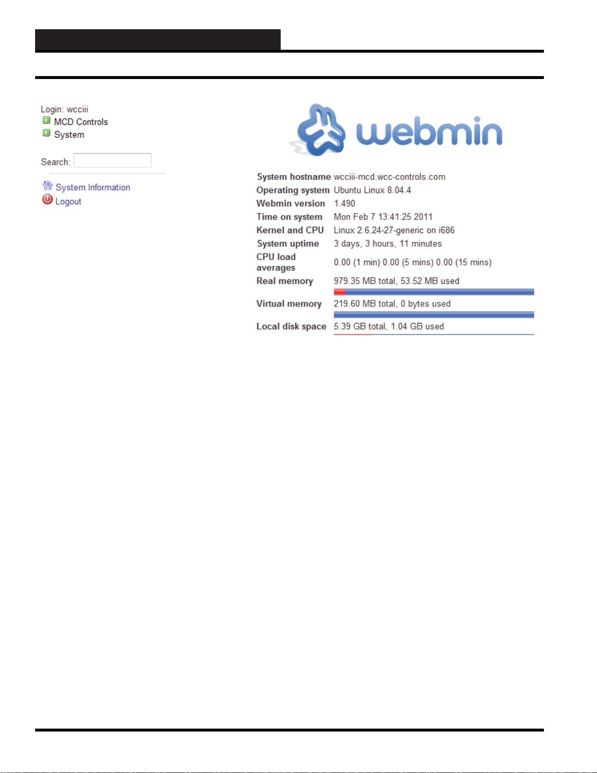
Step 3: If your login is successful, the webmin main page will
display as shown above. Various important static setup information
is displayed under the webmin logo.
System hostname
A hostname is the unique name by which the WCC III –
MCD device is known on a network. The hostname is used
to identify a particular host in various forms of electronic
communication such as the World Wide Web
Operating system
It is the operating system that is running on the WCC III
– MCD. Currently it is “Ubuntu” which is a subversion of
Linux.
Webmin version
This is the version of this program, and this program is used to
administer the WCC III – MCD.
Time on system
System time is measured by a hardware system clock, and this
is the time and date directly from the WCC III – MCD.
Kernel and CPU
This is the sub-version of Linux that the WCC III – MCD is
currently running. And what type of CPU that is in the WCC
III – MCD.
System uptime
Uptime is a measure of the time the WCC III – MCD has been
“up” and running since it have been restarted.
.
CPU load averages
This is a measure of the amount of work that the WCC III -
MCD is doing. The load average is the average system load
over a period of time.
Real memory
Real memory is the actual RAM that is on the WCC III –
MCD CPU board.
Virtual memory
The virtual memory is using hard disk space to increase the
physical memory size of the WCC III – MCD.
Local disk space
This lists the current space available on the Solid State Hard
Drive that is with in the WCC III – MCD.
2-26
WCC III Technical Guide
Page 29

2. INITIATING THE SYSTEM
Webmin Administration - Limited V ersion
On the Left hand side of the Main webmin page is a very limited
subset of the main webmin program sub-categories. These subcategories are used to setup, display, and monitor the operation of
the WCC III – MCD.
MCD Controls See Pages 2-28 to 2-29 for further details. This is
used to turn on and off WattMaster’s Backtask service that should
always be running on the WCC III – MCD.
System See Pages 2-30 to 2-33 for further details. Used to select
and setup the various Webmin administration system options
Search:
Used to search the Webmin application program for a exact specifi c
command, or for general help with the Webmin program.
System Information
This will display the exact same information that is on the right
side of the main menu. See page 2-26.
Logout
This will log you out the Webmin application, and take you back
to the fi rst initial Webmin log in screen. WattMaster Controls, Inc.
only supports the Ubuntu Linux at this time, changing the operating
system will void any and all warranties written or implied that
applies to the operation of the WCC III - MCD.
NOTICE: A knowledgeable computer person should be
used in the setup and deployment of the WCC III – MCD.
This person should also have a good working knowledge
of the Ubuntu Linux operating system and needs to be able
to make changes to the settings other than the WattMaster
Controls factory defaults. These proposed changes should be
sent to WattMaster Controls for written approval before any
changes occur. Failure to having not complied with the above
statements could result in improper operation of the WCC
III – MCD hardware and or software and could cause the
WattMaster Controls control program “Backtask” to function
improperly. Any unauthorized changes will void any and all
warranties, written or implied, that apply to the basic operation
of the WCC III – MCD system.
WCC III Technical Guide
2-27
Page 30

2. INITIATING THE SYSTEM
Webmin Administration - Limited V ersion
MCD CONTROLS
Custom Commands Modules
To ease the management of the WCC III – MCD, these custom
commands were created so that long, cryptic Linux commands
do not have to be entered in the “RUNNING PROCESSES”
command prompt menu. These are script fi les that are run when
selecting the command line or the “Run” button function. You may
edit them with the “edit button” also, but it is not recommended by
WattMaster Controls, Inc.
Named Shortcut Actual Linux Command
prompt usage
Show WCCIII Backtask Status /etc/init.d/backtask status
Stop Backtask Service /etc/init.d/backtask stop
Start Backtask Service /etc/init.d/backtask start
Restart Backtask MCD
Display Service /etc/init.d/backtask-lcd display restart
Restart LCD Driver /etc/init.d/LCDd restart
These commands directly affect the operation of the WCC III –
MCD. So if you stop Backtask service, you should also restart
it when you are done. You must wait approximately 10 seconds
before restarting the Backtask. Service. (Please note that the
Backtask service will automatically restart by itself after a
period of time 2 to 15 minutes).
Selecting “Show WCCIII Backtask Status” will display one of the
following messages:
“Output from /etc/init.d/backtask status ..
Backtask (pid XXXXX) is running”
“Output from /etc/init.d/backtask status ..
Backtask (pid XXXXX) is stopped.”
Selecting “Stop Backtask Service” will display the following
messages:
“Output from /etc/init.d/backtask stop ..
Stopping Backtask... Backtask is stopped”
Selecting “Start Backtask Service” will display the following
messages:
“Output from /etc/init.d/backtask start ..
Starting Backtask...”
And then within 5 seconds, the following message will
display after the end of the above message: “Backtask is
now started.”
Selecting “Restart Backtask MCD Display Service” will display
the following messages:
Output from /etc/init.d/backtask-lcd-
display restart .. Stopping LCD Display... LCD
Display is stopped Starting LCD Display...
And then with in 5 seconds the following message will
display at the end of the above message if everything is OK:
“LCD Display is now started.”
If everything is not OK, error messages can occur such as
the following message:
“Output from /etc/init.d/backtask-lcd-
display restart .. Stopping LCD Display... kill: 74:
Usage: kill [-s sigspec | -signum | -sigspec] [pid | job]... or
kill -l [exitstatus] LCD Display is stopped Starting LCD
Display...”
This message can occur if the “Restart LCD Driver”
command line has been selected and has stopped or
“Killed” the process.
And then within 5 seconds, the following message will
display at the end of the above message if everything is OK:
“LCD Display is now started.”
Selecting
messages:
“Restart LCD Driver” will display the following
Output from /etc/init.d/LCDd restart ..
Restarting LCDd: Stopping LCDd: LCDd. Starting LCDd:
LCDd.
2-28
WCC III Technical Guide
Page 31

System and Serv er Module Screen
This screen sets up a software “watchdog” function on the
“Backtask” program and then makes sure that the Backtask
program is running. If for some reason the “Backtask” program
stops running, this module will send out an Email to a selected
person stating the “Backtask” program is not running.
2. INITIATING THE SYSTEM
Webmin Administration - Limited V ersion
WCC III Technical Guide
2-29
Page 32
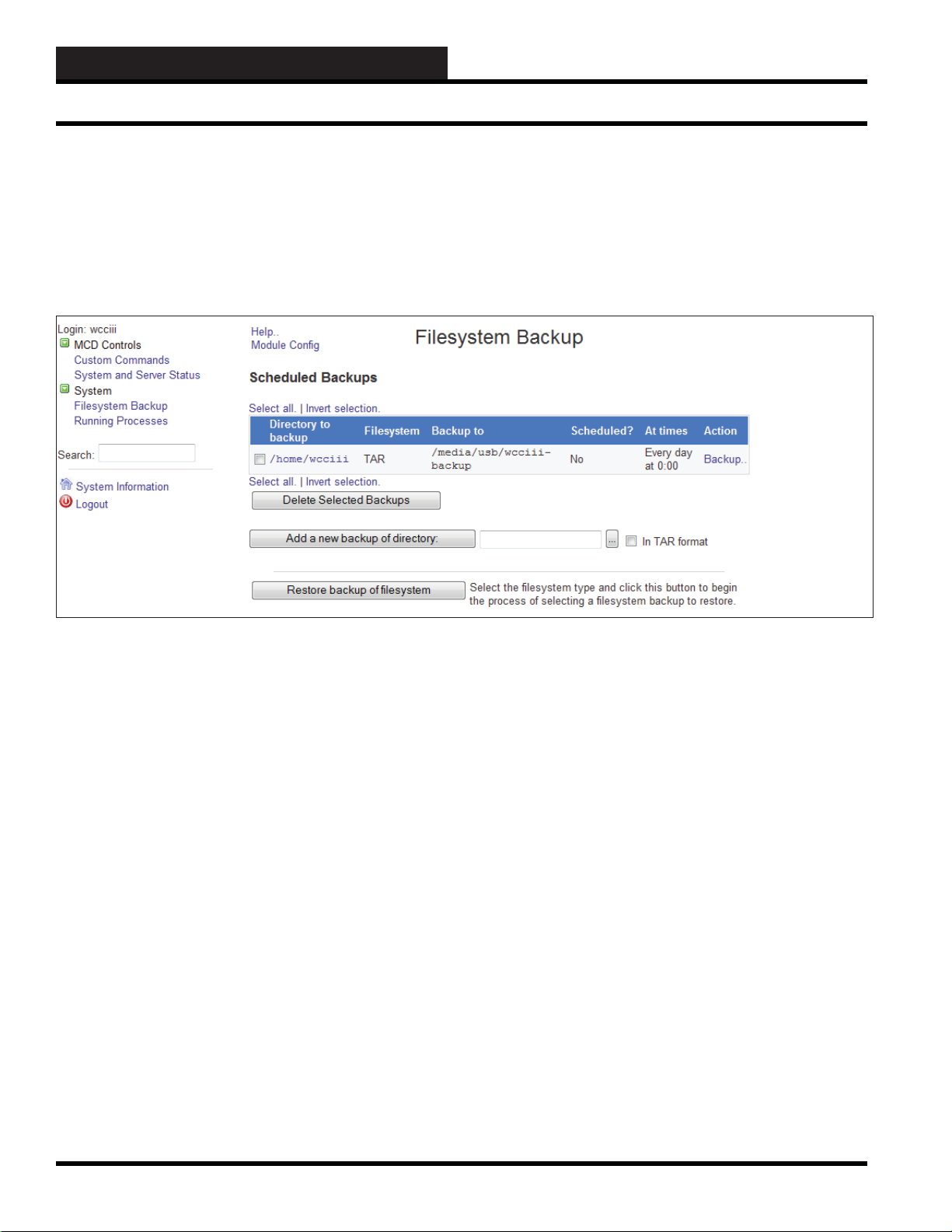
2. INITIATING THE SYSTEM
Webmin Administration - Limited V ersion
The Filesystem Backup Module
This module allows you to create and edit the scripts that are run
at bootup and shutdown time, called actions by the module. The
module can be found under the System category in Webmin, and
when you enter it, the main page will display a list of all available
actions, whether they are started at boot, and a short description
for each.
If this is the fi rst time you have used the module, the table of
backups will be empty.
To create a new backup job, do the following :
1. In the fi eld next to the Add a new backup of directory
button, enter the full path to the directory you want
to save. By default, the module will use the dump
command for backups, but if you prefer tar format
you should select the In tar format checkbox. Then
click the button. The rest of these steps will assume that
you selected the Tar option, as that is the most common
format.
2. On the Add New Backup form, you can add additional
paths to backup to the Directories to backup fi eld.
3. In the Backup to section, you can select File or tape
device if you want to save to a fi le on the same system.
In the adjacent fi eld, either enter a path like /backup/
myfi les.tar, or if you have an attached tape drive use
a path like /dev/st0 (the fi rst SCSI tape drive).
Alternately, you can select the Host option, and enter
a remote hostname, login name, and remote fi le into
the three fi elds next to it. Remote backups are clearly
preferable in most cases as they can be restored if the
system being backed up completely dies!
4. If performing a remote backup, the Remote backup
command fi eld can be used to select the protocol to
use for transferring the backup. SSH is most commonly
used, but FTP is a suitable alternative if you don’t have
an SSH login on the remote system. The default RSH
protocol is almost never used these days.
5. If backing up via SSH or FTP, you will need to enter a
password into the Password for SSH/FTP login fi eld.
This can be omitted if the root user on the source
system has his .ssh directory setup to allow password-
less logins as the destination user.
6. Most of the fi elds in the Backup options section can be
left as their defaults. The only exception is Compress
archive?, which should be set to Gzip or Bzip if your
backup is not to a tape drive.
7. If you want the backup to be run on a regular schedule,
select the Enabled, at times chosen below.. radio
button and enter an email address to notify into the
Email scheduled output to fi eld.
8. Select a schedule to run from the Cron time / date
chooser.
9. Click the Create button at the bottom of the form.
2-30
WCC III Technical Guide
Page 33

2. INITIATING THE SYSTEM
Webmin Administration - Limited V ersion
Running a Backup
Once a backup job has been defi ned, it can be started by clicking
on the Backup.. link in the last column of the backup jobs table.
By default, this will start the job as a foregroup process so that
you can view its progress in the browser. However, for long jobs,
it may be better to run them in the background so that closing the
browser does not interrupt the process. To enable this, click on the
Module Confi g link and change the *Run backups in* option to
Background.
Jobs run in the background (either explicitly started from the web
interface or run on schedule) will be displayed on the module’s
main page under the Running Backup Jobs header. By clicking
on a link in the Action column, you can terminate running jobs, or
if required, signal to the job that a new backup tape is available.
Editing and Deleting Backup Jobs
Once a job has been defi ned, you can edit it by clicking on the
source directory(s) in the fi rst column of the backup jobs table on
the module’s main page. This will bring up the same form as is
shown above, in which all of the job settings can be adjusted.
To delete a job, select the checkbox next to it on the module’s main
page, and click on the Delete Selected Backups button.
Restoring a Backup
If disaster strikes, Webmin can be used to restore backups created
using this module or even backups made manually with the tar
and dump commands. The steps to do this are :
1. Click on the job you want to restore on the module’s
main page.
2. At the bottom of the form, click on the Restore button.
This will bring up a form with the restore source already
fi lled in, as shown below.
3. To restore only some fi les in the backup, select the
Listed fi les option for Files to restore, and enter a
space-separate list of paths into the adjacent text fi eld.
These are typically absolute paths, like /etc/passwd.
4. Enter a destination path into the Restore to directory
fi eld. You can enter / to restore to the original paths,
or something like /tmp to restore elsewhere before
manually verifying the fi les and copying them to their
correct locations.
5. Change the Only show fi les in backup? option to No
if you want to actually restore fi les. When this is set to
Yes, instead of restoring Webmin, it will simply show
you what fi les the backup contains.
6. Click the Restore Backup Now button.
WCC III Technical Guide
2-31
Page 34

2. INITIATING THE SYSTEM
Webmin Administration - Limited V ersion
Introduction to Processes
Every program, process or command running on a Linux system
is a process. At any time, there are dozens of processes running
on your system, some for programs that you are interacting with
graphically, some for commands that you have started at a shell
prompt, some for servers running in the background, and some that
perform system tasks. Every time you type a command like ls or vi
at the shell prompt, a new process is created, only to exit as soon
as its job is done.
Each process is identifi ed by a unique ID, known as the PID or
process ID. Each is owned by a single user and is a member of
multiple groups, which determine the privileges that the process
has. And each has a priority (also known as the nice level), which
controls how much CPU time the process can use up on a busy
system. Almost every process has a parent, which is the process
that started it, and from which it inherits ownership, priority, and
other settings. A process will run until it chooses to exit, or until it
is killed by a signal from another process.
The Running Processes Module
This module can be used to view, kill, re-prioritize, and run
processes on your system. When you enter it for the fi rst time from
the System category, the main page will display a tree of processes
as shown below.
WARNING: Any unauthorized changes to the Webmin
Bootup and Shutdown module will void any and all warranties
written or implied that apply to the basic operation of the WCC
III – MCD system.
2-32
WCC III Technical Guide
Page 35

2. INITIATING THE SYSTEM
Webmin Administration - Limited V ersion
WCC III Technical Guide
2-33
Page 36

2. INITIATING THE SYSTEM
WCC III - MCD Linux Base System Installation
WCCIII – MCD Linux Base System
Install
Install the Software (SS5019)
Step 1: Insert the WCCIII – MCD Ubuntu install CD (WM part
# DM1WC014-XX ) into your external USB CDROM drive and
boot from it. (BIOs must be set to boot from USB device.)
Step 2: Select “English.”
Step 4: You need to determine the end jobsite location where
the WCC III -MCD is going to be shipped to. For the WCC
III - MCD, it is usually one of fi ve selections—Eastern, Central,
Mountain, Pacifi c, or Arizona.
Step 5: Now you need to partition your solid state hard disk.
You want to create one big partition (with the mount point /), so
select Guided - use entire disk.
Step 3: The main WCC III MCD Installation Screen will display
and you will have the following options—Install WCCIII MCD,
Rescue a broken system, Test memory, and Boot from fi rst hard
drive.
Normally, on a new installation, you would select Install WCCIII
MCD and proceed through the rest of the installation software.
This option will install all of the necessary software onto the WCC
III MCD’s solid state hard drive.
Step 6: Select the disk to partition. You should select the SCSII
(0,0,0) sda - 8.0GB ATA Transcend (image may be different, but
select sda).
2-34
WCC III Technical Guide
Page 37

2. INITIATING THE SYSTEM
WCC III - MCD Linux Base System Installation
Step 7: When prompted, you should highlight and select Yes
when you’re asked, “Write the changes to the disks?” Your new
solid state hard disk partitions are now being created and formatted.
Step 8: Now the base Linux Ubuntu operating system is being
installed, and the installation screen should be displaying the
various different fi les’ information in the middle of this screen. The
installation process has been automated and there should not be
any prompting for further information unless a problem occurs.
III - MCD is installed and is now creating the wcciii user account
information, installing the backtask program, and installing other
minor assorted fi les that are needed for proper operation of the
WCC III - MCD.
Step 11: The base Linux operating system installation is now
fi nished. You must now remove the USB key and press <Continue>
to reboot the WCC III - MCD system.
Step 9: The Linux operating system installation continues for 3-5
minutes at which point other non Linux operating system software
is also installed such as the webmin interface.
:
Step 10: At this point, the Linux operating system for the WCC
WCC III Technical Guide
2-35
Page 38

2. INITIATING THE SYSTEM
Setting Up a Direct Connection from a Stand-Alone Computer
How to Setup a Windows-Based
Local User’s Computer with a Direct
Connection (Ethernet Crosso ver
Cable) to the WCC III - MCD
Computer
There are times when a WCC III - MCD may never be networked
or connected to the internet. In these instances, it will be required
to install the WCC3 group of programs on a “Stand-Alone”
Windows-based computer so that the end user can program and
control the operation of the WCC III – MCD. For these “standalone” applications, it is possible to connect the WCC III – MCD
to a single Windows-based computer for the end user with an
Ethernet crossover cable. The current WCC3 programs-supported
Windows versions are Windows 98SE, Windows XP - Pro,
Windows Vista, and Windows 7.
The Windows-based local user’s computer will need to be setup at
a “new” known IP address so that the WCC III –MCD can connect
to it. This IP confi guration should be done by trained network
IT personnel. You must change a couple of network settings
that if done improperly could adversely affect the operation of
the local user’s computer, but they are not diffi cult if you take a
couple of minutes to understand what is going on.
We will use a Laptop computer and a WCC III – MCD that
is running Linux Ubuntu as our example machines in this
example. The Laptop machine will be running some variant
of the Windows operating system other than Windows NT
Server or Win2000 Server. The WCC III – MCD that is
running Linux Ubuntu is already pre-programmed from the
WattMaster factory to use this secondary IP numbering scheme.
On the Laptop computer you will need to start by getting into the
Network Neighborhood settings. Either right click on the Network
Connections icon and select properties or go through the control
panel to get to these settings.
On the Laptop - machine 1, check to see if you are using
DHCP. DHCP will not work in a crossover connection,
and you will need to set a static IP address. We will need to
change the IP address settings only on the Laptop machine,
because the WCC III – MCD is already programmed from
the factory to use this secondary IP numbering scheme:
IP Addressing Scheme: Make sure the fi rst three octets are the
same and the last octet is different.
(XXX.XXX.XXX.XXY) Both IP addresses - All XXX should be
the same, and the last digit “Y” should be different.
Example:
WCC III – MCD IP SETTINGS: 192.168.200.200 (Already
preprogrammed at the Factory)
LAPTOP Machine IP SETTINGS: 192.168.200.201
The subnet mask entry must also be identical on both
machines.
Example: 255.255.255.0
Close the network neighborhood, and you should be
prompted to reboot. Make sure the computers are linked
using your special cable. After the reboot, go to the network
neighborhood of one of the computers. The other machine’s
network name should be visible to you!
Important note: Only one Windows-based local user
computer can be connected to the WCC III – MCD computer
using this simple Ethernet crossover cable method.
Why use the 192.168.XXX.XXX for IP Addressing?
In Internet Protocol terminology, a private network is typically
a small network that uses a predefi ned private IP address space,
following the standards set by RFC 1918 and RFC 4193. These
addresses (192.168.XXX.XXX) are very common in home
and small offi ce local area networks (LANs) because globally
routable addresses are scarce, expensive to obtain, or their use
is not necessary. These addresses (192.168.XXX.XXX) are
private because they are not globally delegated, meaning they
aren’t allocated to a specifi c organization. Anyone can use these
addresses without approval from a regional Internet registry (RIR).
Consequently, they are not routable within the public Internet. If
such a private network needs to connect to the Internet, it must
use either a network address translator (NAT) gateway or a proxy
server.
Ethernet crossover cable
An Ethernet crossover cable is a type of Ethernet cable used to
connect computing devices together directly where they would
normally be connected via a network switch, hub, or router such
as directly connecting two personal computers via their network
adapters.
An Ethernet Crossover cable is a special Ethernet cable with the
sending and receiving wires switched on opposite ends. When two
computers are connected with this cable in the normal RJ45 port,
you have the ability to create a local workgroup style network
between the two machines. This of course is not a replacement for
a normal network connection, but can be a great way to ‘Transfer’
large fi les between two machines.
2-36
WCC III Technical Guide
Page 39
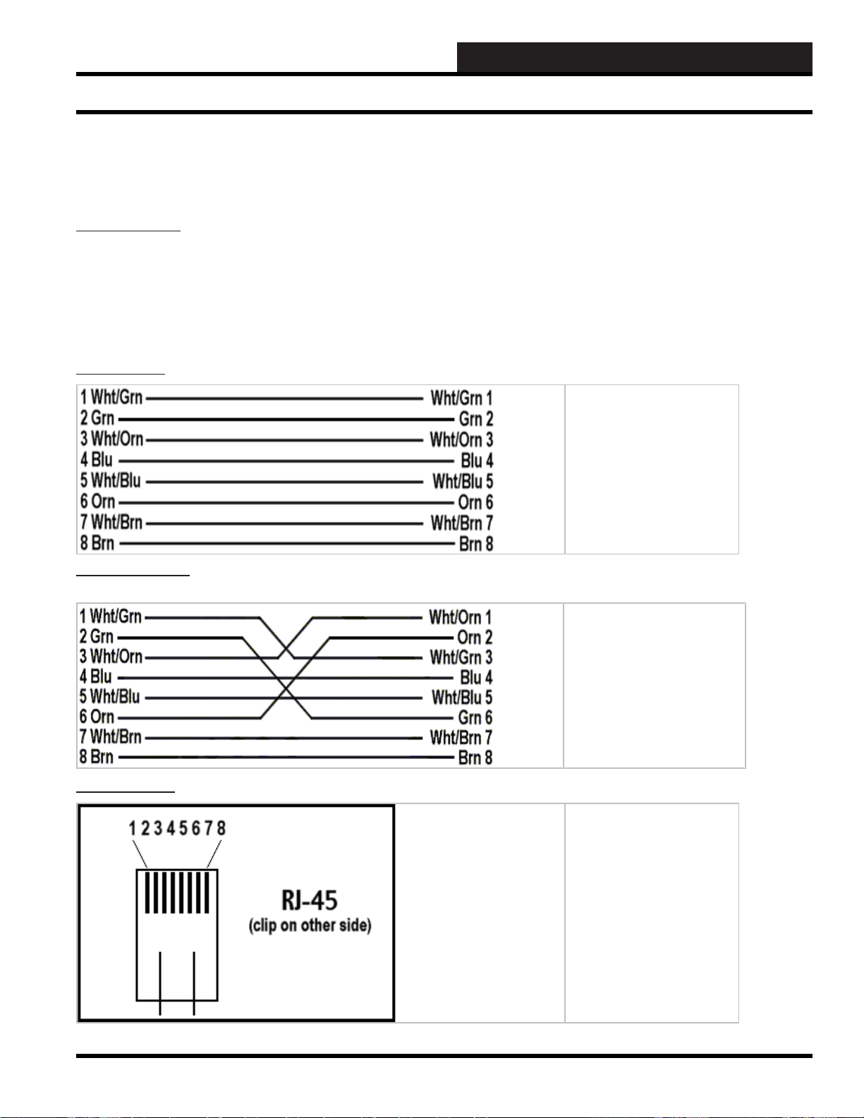
Setting Up a Direct Connection from a Stand-Alone Computer
You must change a couple of network settings, but they are not
diffi cult if you take a couple of minutes to understand what is
going on.
Cable Drawings
All network 10/100 baseT cables use 8-conductor, unshielded
twisted-pair (UTP) wire. Category 5 wiring should be free of tight
kinks and should be protected from pinches caused by fasteners,
staples, cable ties, etc. Loose excess cabling must not be coiled up
in loops. A cable from the hub to a PC may not exceed 328 feet in
length.
Standard Cable
2. INITIATING THE SYSTEM
Standard CAT5 cables are
used to connect PCs to the
network hub or network
switch. They are also used
to connect the WCC III –
MCD to a network hub,
network switch, or DSL/
Cable modem.
Crossover Cables (WattMaster Part # HZ000136 – 6 foot
long)
RJ-45 Diagram
Crossover cables are
designed to connect hubs
together, expanding the
capacity of a network.
Crossover cables may also
be used to connect a single
Windows-based computer
to a WCC III – MCD without
the use of a network hub or
network switch.
10/100 baseT cables use
RJ-45 connectors on the
ends. The diagram shows
how to determine the
correct pin numbers on
these RJ-45 connectors.
WCC III Technical Guide
2-37
Page 40

2. INITIATING THE SYSTEM
Setting Up a Direct Connection from a Stand-Alone Computer
Step by Step Instructions
To get the “Network Connections” icon you must be able to
navigate to the control panel settings so that you can proceed with
the IP modifi cations for connecting a computer to the WCC III –
MCD with an Ethernet crossover cable.
The Network Connections Icon
The Network Connection icon is used as an initial setup point for
IP settings. Double left click on the Network Connections icon with
your mouse button. This should have now taken you to the Network
Connections dialog screen with the “The Ethernet Icon”.
The Ethernet Icon
Network Connection settings. Double left click on the Ethernet
icon with your mouse button. This should have now taken you to
the Ethernet Status dialog screen.
At the Ethernet Status dialog screen select the “Properties”
button by double left clicking on the “Properties” button with
your left mouse button. This should have now taken you to the
“Ethernet Properties” dialog screen.
Ethernet Properties dialog screen
At the Ethernet Properties dialog screen select the “Internet
Protocol (TCP/IP)” choice fi eld with a single left click of the
mouse to highlight the “Internet Protocol (TCP/IP)” choice fi eld.
Next, using your mouse, double left click on the “Properties”
button. This should have now taken you to the Internet Protocol
(TCP/IP) Properties dialog screen.
Ethernet Status dialog screen
2-38
Internet Protocol (TCP/IP) Properties dialog screen
WCC III Technical Guide
Page 41
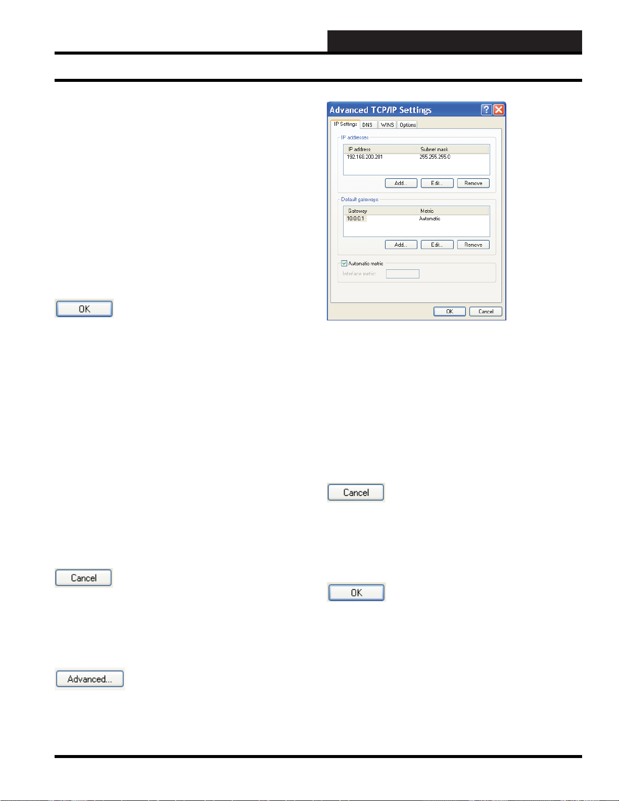
Setting Up a Direct Connection from a Stand-Alone Computer
At the Internet Protocol (TCP/IP) Properties dialog screen you
must select the “Use the Following IP address” radio button by a
single left click of the mouse to select the radio button to the left of
the “Use the Following IP address”.
You are required to enter the IP address, Subnet mask, and Default
gateway at this point. These standard values are used so that you
can easily connect to the WCC III – MCD with the minimal amount
of IP confi guration setup.
These are the correct values that should be entered for the IP
address, Subnet mask, and Default gateway.
IP address 192.168.200.201
Subnet mask 255.255.255.0
Default gateway 10.0.0.1
2. INITIATING THE SYSTEM
The OK button
Remember to hit the “OK” button with a single left click of the
mouse to save these values. It will also take you back to the previous
Ethernet Properties dialog screen. You should now be done setting
up the IP confi guration for the “How to setup a Windows-based
local user’s computer for WCC3 with direct connection (Ethernet
Crossover cable) to the WCC III – MCD computer”. You will have
to hit the “OK’ button again on the “Ethernet Properties” dialog
screen with the left button of your mouse, which will then take
you back to the “Ethernet Status” dialog screen. At the “Ethernet
Status” dialog screen you should now hit the “Close” button on the
Ethernet Status dialog screen with the left button of your mouse to
close this screen. At this point, any other open Windows screens
(Network Connections and Control Panel) should be closed out or
shut down with the close down box in the upper right hand corner.
It is good practice to restart the computer at this point for these
settings to be applied. Also, make sure that the Ethernet crossover
cable is connected from this computer to the WCC III – MCD at
this point.
The Cancel button
The Cancel button is used to cancel the IP changing operation of
this screen. It will also take you back to the previous Ethernet
Properties dialog screen.
Advanced TCP/IP Settings Dialog Screen
An IT person may also want to visit this “Advanced TCP/IP Settings
Dialog” screen to add or remove other unwanted IP addresses and/
or Default gateways with this screen. There are situations where
you can have multiple IP addresses with multiple gateways. This
would require advanced knowledge of how the internet / intranet
works.
Additionally, there are “Tabs” for DNS, WINS, and OPTIONS
settings. These are typically not used on this confi guration of
connection to the WCC III - MCD.
The Cancel button
The Cancel button is used to cancel the IP changing operation of
this screen. It will also take you back to the previous Ethernet
Properties dialog screen.
The OK button
Remember to hit the “OK” button with a single left click of the
mouse to save these values. It will also take you back to the
previous Internet Protocol (TCP/IP) Properties dialog screen.
The Advanced button
The Advanced button is used to access the Advanced TCP/IP
Setting screen.
WCC III Technical Guide
2-39
Page 42

2. INITIATING THE SYSTEM
Adding A Flash Hard Drive Card
Adding a Compact Flash Hard Drive
Card to the WCC III - MCD Computer
Under Windows XP on the WCC III MCD
Before you install the Linux Operating System, the fl ash hard
drive card needs to be installed.
Step 1: Properly shut down the WCC III - MCD computer.
Step 2: Insert the additional non-volatile Compact Flash
(CF) card to the CF card holder in the back of the Single
Board Computer PCI-6881 circuit board. CF cards can supply
additional storage that will behave much as a hard drive does
in a typical PC with a 2GB size currently installed in the
WCC III-MCD. These Compact Flash products are inherently
more rugged than a hard drive since they are completely
solid-state with no moving parts. The Compact Flash hard
drive acts as a secure data back up for the WCC III - MCD
computer.
Step 3: The BACKTASK program will make a new
subdirectory on the Compact Flash drive every month that is
based on a month / year fi le structure. In this “month / year”
subdirectory that is created every month, you will fi nd the last
daily data fi les back up for the month – either on the 28
st
or 31
, depending on the month. The Compact Flash hard
drive in the WCC III - MCD stores the BACKTASK data
fi les on it every day at midnight. Also, the current identical
fi les will also co-exist in the BACKTASK subdirectory on the
WCC III - MCD.
th
, 30th,
Since the Compact Flash card appears as a standard IDE drive
on the WCC III-MCD, it uses no additional RAM for drivers.
In a Windows XP operating system, the Compact Flash drive
on the WCC III-MCD must be mapped to drive letter “E”.
This is accomplished with the following instructions:
Step 4a: Reconnect the power to the WCC III-MCD
computer and allow it to boot up normally.
Step 4b: Left click My Computer and from the pull down
menu, select Properties. The following screen will appear.
Step 4c: Right click on Disk Management.
Step 4: All of the Satellite data will need to be retrieved
from the WCC Utilities Program. The Satellite data is usually
in the specifi c jobsite subdirectory, because the WCC III-
MCD BACKT ASK Program does not store these fi les. These
fi les can be downloaded and then saved from any of the pre-
existing SAT III type controllers at the jobsite.
The 2GB Compact Flash card has the added advantage of
being removable media. A Compact Flash reader with writer
device may be needed at the host PC for fi le transfers. This
results in the ability to quickly move fi les from a host PC to
the WCC III - MCD using a Compact Flash card as the
removable media.
2-40
WCC III Technical Guide
Page 43

2. INITIATING THE SYSTEM
Adding A Flash Hard Drive Card
Step 4d: Next, right mouse click on the TRANSCEND drive
under the “Volume label” (or other manufacturer of the Compact
Flash hard drive). A pull down type menu will appear. Right
click on “Change Drive Letter and Paths…”
Step 4e: Select and highlight the current Compact Flash hard
drive, and then click the Change button.
(Right Mouse Click selects it)
Step 4f: Using the drive letter selection button, select the
drive letter “E” , and only “E”.
Then select the “OK” button to exit this program, and keep
selecting the “OK” or “APPLY” buttons until you are back at
the main desktop menu again. Using the “My Computer” icon
please confi rm that the Compact Flash drive assignment is
now set at drive letter “E”, and “E” only.
WCC III Technical Guide
2-41
Page 44

2. INITIATING THE SYSTEM
Formatting Disks
Formatting Disks
The fi rst step in copying disks is to format the disk which will serve
as the “Target Disk.” After the disk has been formatted, the system
can direct the fi les to be stored in certain places.
WARNING: Make sure that the disk that you format does not
contain any programs that you want to save. The formatting
process will erase everything presently on the disk.
To format a disk
1. If the disk you want to format is a fl oppy disk, insert it
into its drive. Otherwise, skip to step 2.
2. Open
3. On the File menu, point to the name of the fl oppy drive,
4. Specify the following options:
<My Computer>*, and then click the disk you
want to format.
and then click
<Format>.
• Capacity
• File system
• Allocation unit size
• Volume label
• Quick Format**
• Enable Compression (NTFS only)
• Create an MS-DOS startup disk
5. Click <Start>.
* To open My Computer, click
Computer>.
** Quick Format removes fi les from the disk without scanning
the disk for bad sectors. Use this option only if the disk has been
previously formatted, and you are sure the disk is not damaged.
NOTE: You cannot format a disk if fi les are open on the
disk, the contents of the disk are displayed, or the disk
contains the system or boot partition.
You can also format a disk by using Disk Management. For more
information, click Related Topics.
<Start>, and then click <My
Copying a File or F older to a Diskette
To copy a fi le or folder to a fl oppy disk:
6. Insert the fl oppy disk into the disk drive.
7. Open
8. If the fi le or folder you want to copy is not located
9. Click the fi le or folder you want to copy. To select more
10. Under File and Folder Tasks, click <Copy this fi le>,
11. In Copy Items, click <3 1/2 Floppy (A:)>, and then click
*To open My Documents, click
Documents>.
You can also copy a fi le or folder to a fl oppy disk by right-clicking
the fi le or folder, pointing to
Floppy (A)>.
After you copy fi les or folders to the diskette, it is useful to view
the diskette to confi rm that the fi les are copied.
<My Documents>*.
in My Documents or its subfolders, use Search to
fi nd it. To open Search, click <Start>, and then click
<Search>.
than one fi le, hold the
fi les you want.
<Copy this folder>, or <Copy the selected items>.
<Copy>.
<Ctrl> key while you click on the
<Start>, and then click <My
<Send To>, and then clicking <3 1/2
Copying a File or F older to a USB
Flash Drive
To copy fi les and folders to a USB fl ash drive:
12. Insert a USB fl ash drive into the USB port.
13. Open
14. Click the fi les or folders you want to copy to the fl ash
15. In the Copy Items dialog box, click the USB drive, and
16. In My Computer, double-click the USB drive and verify
<My Computer>*.
drive. To select more than one fi le, hold down the
<Ctrl> key while you click the fi les you want. Then,
under File and Folder Tasks, click
<Copy this folder>, or <Copy the selected items>.
then click <Copy>.
that the fi le(s) were copied to the USB device.
<Copy this fi le>,
2-42
* To open My Computer, click
Computer>.
WCC III Technical Guide
<Start>, and then click <My
 Loading...