

Page 1
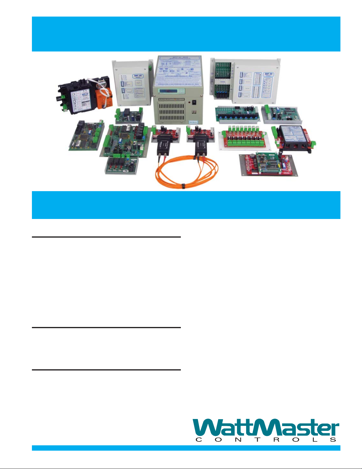
WattMaster Control Center
WCC III
WCC III Provides Complete Control and Energy
Management for Any Size Facility
Economical For Small Systems
Because Of Modular Construction
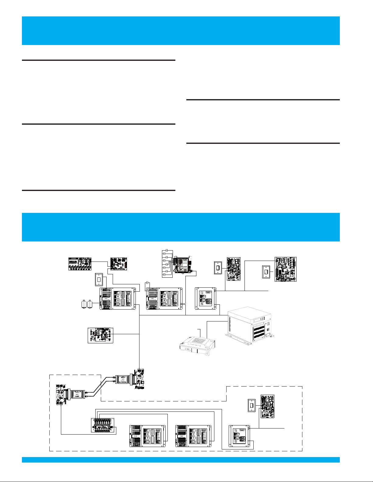
The WCC III System is comprised of an MCD that operates primarily as a distribution point for control
schedules and data used/shared by direct digital control panels (satellite controllers and terminal unit controllers) which are distributed throughout the building.
Satellite controllers and terminal unit controllers
provide the actual control and are added and programmed to suit your specifi c system requirements.
Menu Driven Program Makes System
Set-up Easy And System Operation
Even Easier
All steps of the WCC III operation including initial satellite
controller set-up are menu driven. This means operators
do not have to be system programmers, and changes can
be made without referencing a complex computer program.
Reduced Costs
Equipment Cost is reduced because the system, including satellite controllers, is modular. You only buy the number of satellites required. Satellites have capacity for 8 selectable inputs (analog or binary), 16 binary and 8 analog
outputs, and there are expansion boards available to extend binary inputs and outputs along with analog outputs.
Direct Digital Control further reduces costs because
satellite controllers interface directly with valve and damper actuators, eliminating costly intermediate controls.
Terminal Unit Controllers Reduces Wiring Costs:
Use of terminal unit controllers further reduces installed
costs by greatly reducing fi eld wiring and often allow-
ing factory installation of controls on terminal units to
reduce fi eld labor and wiring errors. Special satellites
and terminal unit controllers are available to control fan
coil units, heat pumps, and pressure dependent and
pressure independent VAV and fan terminal boxes.
Operating Costs are reduced through menu driven programs, including adaptive optimal start, demand limiting,
deadband spreading, duty cycling, night setback, and other programs you can create for your specifi c requirements
thru the logic programs related to global commands.
Equipment Replacement Costs drop because equipment lasts longer. Close monitoring and logging of
performance and run time means service needs can
be recognized before a serious breakdown occurs.
Improved Cost Management: Equipment and lighting are precisely controlled during “normal occupancy
hours”. After hours override by tenants permits logging or extra usage so that costs can be properly allocated to tenants/departments using extra energy.
Installation Cost is reduced because “Global” information gathered at one satellite can be shared with other
satellites, eliminating wiring runs and control duplication.
Page 2
WCC III Provides
Comfort And Monitoring Features
Improved Comfort
Happy People: Comfortable tenants do not move out,
and comfortable employees work more effi ciently . The
WCC III is designed to monitor and control each terminal
unit in the building. Control is precise, and alarms are displayed when any temperature exceeds limits. Corrective
action can be taken before occupants become aware of
a problem.
Tenant Override and Report:
The override allows up to 500 different tenants to override
lights, heat, and air conditioning (or other functions) for a
selectable time period. Overrides are logged and totaled
by tenant and subcode for monthly billing purposes. Up to
12 month log is stored by month for each tenant.
Remote Monitoring/Alarm E-mail
Increases Effi ciency For Owners
Of Multiple Buildings
The WCC III system is supplied with remote access for
authorized operators. Setpoints, schedules, etc., may be
WCC III Typical
changed and system status monitored from this remote
location. Thus, the performance of multiple buildings can
be monitored from a single location and alarm reports automatically received at this or any other location through
the alarm e-mail function of the WCC III.
Enhanced Graphic Option
An enhanced graphics program (WGCC3) with standard
symbols and drawing package is available for the user desiring further refi nement of graphic capability. This is an
optional upgrade.
Internet Access:
Improves communication on large facilities: The ability
to have multiple operators that can have access to the
system simultaneously. This truly optimizes system performance by coordinating all service maintenance and
operators’ input in one operating program.
Optional B-OUT Board
( 8 RELAYOUTS)
(2 PER SATIII)
OE210
TYPICAL
SENSOR
(X8)
ON/OFF RELAY
PUMPS, LIGHTS,
ETC.
16 OUTPUTS
PER SATIII
WCC II TO WCC III
GLOBAL BRIDGE
CONNECTION
TO OLD WCC II
MANCHESTER
COMM LOOP
WATTMASTER CONTROLS INC
SATII
UP TO 60 TOTAL SAT III
OR SAT3C/D/F/P PER LOOP.
THERE ARE 4 POSSIBLE
SATIII RS485
COMMUNICATIONS LOOPS
(UP TO 239 SAT III MAXIMUM)
BUILDING # 2
PL102335
RS-485 TO FIBER
OPTIC ADAPTOR
USUALLYONE
OR TWO PER
FLOOR
SATCOMM LOOP
P 102224L
POWER AND
SWITCHABLE COMM
Optional B-INPUT Board
( 8 BINARY INPUTS)
(2 PER SATIII)
HSS PORT
GLOBALBRIDGE
PROGRAM SOCKET
YS102210 REV 1
MADE IN USA
ADDRESS
R/T
SHLD
PCF8583
C
COMMT
EEPROM
24C128
POWER
SATII STAT
485
COMM R
DRIVER
LT1785
SATIII
VBAT
COMM
24VAC
CHASSIS GND
GND
FIBER OPTIC LINES
MAXIUM OF 2.5 MILES
(USES "ST" CONNECTORS)
SATCOMM LOOP
System Schematic
OE455-P
SAT3P
CONTROLLER
PULSE INPUTS
P1
SATIII-P
PULSE METER BOARD
P2
ATTMASTER CONTROLS
YS102268 REV0
P3
MADE IN USA
P4
PULSE 1
P5
PULSE 2
TOTALWIRING FOR EACH INPUTNOT
PULSE 3
TO EXCEED 100 FEET.
P6
USE 18 GAUGETWISTED PAIR WITH
PULSE 4
SHIELD FOR EACH PULSE METER
PULSE 5
CONNECTION.
P7
PULSE 6
CONNECTTHE SHIELD WIRETO GND.
PULSE 7
P8
PULSE 8
STATREC
“P”MODEADDRESSING NOTES
GND
SATIIIADDRESSING STARTSAT
STATXMIT
ADDRESS NUMBER 8.
LOCALSET
EACH "P" MODE SATIIITAKES UP
GND
STATUS
(8) SATIII LOGICALADDRESSES.
THEREARE ONLY(8) USEDACTIVE
INPUTS PER SAT3P.
OPTIONS
ADDRESS
ANALOG INPUT#1 (PULSE INPUT#1)
SEL
ADD
ON EACH SATIIIADDRESS ISACTIVE.
1
ALLOTHER INPUTSAND OUTPUTS ON
TEST
THE SAT3PARE NOTFUNCTIONAL.
LOCAL
2
LDIS
4
OPT1
8
OPT2
16
OPT3
32
64
128
COMM
POWER
24 VAC
R
SH
GND
T
OE454/OE455/OE456
SAT3C/D/F
CONTROLLER
HIGH SPEED CABLE
MODEM / DSL ROUTER
SATCOMM LOOP
OE421- SATIII
CONTROLLER
OE213
TYPICAL
SENSOR
ETHERNET
CABLE
HSS PORT
MULTIPLE PULSE
INPUTS FROM
POWER METERS
SINGLE PULSE
INPUT FROM
POWER METER
OE421- SATIII
CONTROLLER
TO THE ISP
(INTERNET SERVICE PROVIDER)
CONNECTION TO THE INTERNET
(BY OTHERS)
PL102335
RS-485 TO FIBER
OPTIC ADAPTOR
USED IN MULTIPLES
OF TWO
OE421- SATIII
CONTROLLER
OE320
TUC-2R
VAV B O X
WCC III-MCD
OE213
TYPICAL
SPACE
SENSOR
OE455
SAT3D
CONTROLLER
OE213
TYPICAL
SENSOR
OE320
TUC-2R
VAV B O X
TUC COMM LOOP
UP TO 32 TOTAL
FAN COIL, HEAT PUMP
PD VAV TERMINAL UNITS
PI VAV TERMINAL UNITS
PARALLELFAN BOX, ETC.
OE331
TUC-5R+
HEATPUMP
UP TO 32 TOTAL
FAN COIL, HEAT PUMP
PD VAV TERMINAL UNITS
PI VAV TERMINAL UNITS
PARALLELFAN BOX, ETC.
Page 3

WCC III Provides
These Specifi c Features
Function Benefi t
Menu Driven Software Easiest system to operate on the market today
Sort By Descriptions
Automatic Daylight Savings Correction
Linux-Based Software Embedded system approach from the start
Capacitor Backup Memory for the Satellite Memory Protection from 72 plus hour power failure
Program Flow Trace Simplifi es program analysis on large systems
Multiple (8) Alarm Levels Reduces nuisance alarms
E-mailing of Alarms Improves service /maintenance support
Automatic Alarm Printout Provides hard copy record of alarms
Data Copy Functions Reduces set time and errors
Adaptive Optimal Starts (64 programs) Optimizes energy use and comfort
Demand Limiting, Deadband Spreading
Morning Warm-up Program Controlled warm-up maximizes comfort
Controlled Restart after Power Outages Prevents breaker lockout from electrical surges
Softstart for Morning Warm-up Reduces electrical surge and demand peak problems
Isolated RS-485 Communications to SATs Reduces damage from voltage surges
Fiber Optics Reduces damage from voltage surges
Multiple Levels of Operator Security Codes Prevents unauthorized access to program level
Temporary Overrides - Locally or Remotely Permits temporary schedule changes by the tenant or
maintenance
Analog Input Simulation Aids in service and system checkout and reduces
start-up time
Analog Input Trend Logs Log (and graph) of all analog inputs improves system analysis
Extreme Trend Logs Helps determine system performance
Change of State Logs Documents equipment operation time/characteristics
Runtime Accumulation Improves service, maintenance, and after hours billing
capabilities
Analog Comparison, Boolean Logic Optimizes system performance and minimizes energy use
Math Operators/Enthalpy Logic Energy consumption is reduced with customized
programs
User Confi gurable Lookup Tables Precise readout from nonlinear inputs
Event Initiated Logic Reduces wiring interlocks costs
Signal Selection/Averaging Optimizes reset schedules from selectable loads
Proportional Reset/Graph Reduces energy use, stabilizes control, and graph
simplifi es readout
Programmable Switch Hysteresis Extends equipment life by reducing cycling
Programmable Filter Time Constants Improves system stability and performance
Multiple Demand Limiting Ten energy consumption screens fi t multiple meter
facilities
Remote Monitoring/Uploading/Downloading Improves service capabilities
Internet Based Communications Accessible from anywhere
Terminal Unit Interface (Sat3 c/d/f) Reduces installed cost
Duty Cycling User Defi nable Versatile program for special applications
Page 4

WCC III
Technical Specifi cations
WCC III added system improvements over the WCC II
system:
SAT III controller added improvements over the SAT II
controller:
Recommended Computer for the WCC III program:
• Increased the Global Analogs from 128 to 256
• Increased the Global Binaries from 256 to 512
• Increased the Week Schedules from 32 to 128
• 16 dedicated PID programs
• Since the system is now internet based,
multiple workstations are now supported.
• Relay outputs instead of “Chipswitches”
• LED status indicators for the relay outputs
• HSS expansion port – supports new Binary
Input, Binary Output boards.
• Added HSS Binary Outputs to SAT III (Up to
16 more relay outputs)
• The SAT III has a 12 bit A to D converter,
while the SAT II has a 10 Bit A to D converter.
• Analog Inputs of 0 to 1 VDC, 0 to 5 VDC, 0 to
10 VDC, 4 to 20mA, and Thermistor sensors
are now supported.
• Pentium 4 computer or better that is running
at 2 GHz or faster
• 1 Gig RAM minimum
• Windows XP-Pro
• 80 Gig Hard Drive or larger
• High Speed internet access (cable modem
preferred)
• Printer (optional for data print outs)
Computer Power Requirements (WCC III-MCD):
SAT III Power Requirements:
Communications Loop:
Internet Access Requirements:
Operating Temperature:
• 96 to 143 VAC 50/60 Hz 200 Watts
• Use dedicated 120 VAC circuit (4-3 wire
ground plug required)
• (UPS is recommended)
• 24 VAC @ 1 Amp
• Each communications loop communicates
with up to 60 SATs. (4 loops are possible)
• Communications wire is 18 gage twisted with
shield.
• 4000 feet to furthest Satellite.
• Fiber Optics
• High Speed Access (cable modem is
preferred)
• 50 to 100 degrees Fahrenheit, 10% to
90% (non condensing)
Form: WM-WCCIII-SBR-01D Printed in the USA October 2011
All rights reserved. Copyright 2011
WattMaster Controls Inc. • 8500 NW River Park Drive • Parkville, Mo. · 64152
Phone (816) 505-1100 www.wcc-controls.com Fax (816) 505-1101
 Loading...