

Page 1

Operator’s Guide
www.wattmaster.com
www.wattmaster.com
Operator’s Guide
WCC II
Page 2

WattMaster Controls, Inc.
8500 NW River Park Drive · Parkville, MO 64152
Toll Free PH: (866) 918-1100
PH: (816) 505-1100 · FAX: (816) 505-1101 · E-mail: mail@wattmaster.com
Visit our web site at www.wattmaster.com
Form: WM-WCCII-OGD-01A Copyright 2006 WattMaster Controls, Inc.
WattMaster Controls, Inc. assumes no responsibility for errors, or omissions.
This document is subject to change without notice.
Page 3

WCC II Operator’s Guide
Table of Contents
INTRODUCTION: SYSTEM OVERVIEW ......... I-1
Diagram of WCCII System ................................... I-1
Operator Control Console Components .............. I-2
Satellite Controller .............................................. I-2
SAT II .............................................................................I-3
SAT II-A ..........................................................................I-3
TUC Input/Output Features .........................................I-3
SAT II-B ..........................................................................I-3
System Features .................................................. I-4
Standard Software ........................................................I-4
Optional Enhanced Color Graphics ............................I-4
Optional Tenant Override ............................................I-4
System Size ..................................................................I-4
Modular Construction ..................................................I-4
SECTION 1: GENERAL INSTRUCTIONS ...... 1-1
“Where To Find” Features ................................... 1-1
ECC/WCC II Routine Maintenance ...................... 1-1
ECC/WCC II Software Version List ..................... 1-2
Recommended Data Entry Procedure ................ 1-3
Analog Inputs ...................................................... 1-3
Binary Inputs....................................................... 1-4
Analog Outputs ................................................... 1-5
Binary Outputs .................................................... 1-6
Point Addresses .................................................. 1-7
Data Registers .................................................... 1-8
Time Clock ...................................................................1-8
EA Driver ......................................................................1-9
Dual Limit .....................................................................1-9
Alarm Print-Out and Call-Out ............................ 1-10
Run Time Alarm .........................................................1-12
Satellite Fail Alarm ....................................................1-13
Operator Sign On/Off ........................................ 1-13
Manual Overrides .............................................. 1-13
System Re-Boot ................................................ 1-13
Hardware Requirements ................................... 1-13
SECTION 2: INITIATING THE SYSTEM......... 2-1
Dual Disk Drive Systems ..................................... 2-1
Hard Disk Drive Systems .................................... 2-2
Copying Disks ..................................................... 2-2
Formatting Disks................................................. 2-2
Copying Data - Dual Floppy Systems .................. 2-4
Copying Data - Hard Disk Drive Systems ........... 2-4
Returning to the ECC/WCC II Program ............... 2-6
Dual Disk Drive Systems ............................................2-6
Hard Disk Drive Systems ............................................2-6
Assign Operator Access Codes .......................... 2-6
Password Entry ................................................... 2-7
SECTION 3: SCREEN DESCRIPTIONS ......... 3-1
HELP SCREEN ..................................................... 3-1
MAIN MENU SCREEN .......................................... 3-5
ANALOG INPUT SUMMARY SCREEN .................. 3-7
ANALOG INPUT SCREEN .................................... 3-9
CONTROL OUTPUT SCREENS .......................... 3-12
CONTROL OUTPUT SUMMARY SCREEN ...............3-13
EA DRIVER SCREEN .................................................3-15
DUAL LIMIT SCREEN ................................................3-17
TIMECLOCK SCREEN ...............................................3-20
ANALOG OUTPUTS ........................................... 3-22
ANALOG OUTPUT SUMMARY SCREEN ..................3-22
ANALOG OUTPUT SCREEN .....................................3-24
TREND LOGGING .............................................. 3-25
TREND LOGGING SUMMARY SCREEN ...................3-26
ANALOG PEAK TREND LOG SCREEN ....................3-27
ANALOG TREND TREND LOG SCREEN .................3-28
CHANGE OF STATE TREND LOG SCREEN ............3-31
RUN TIME TREND LOG SCREEN .............................3-32
LOGIC SWITCH .................................................. 3-34
LOGIC SWITCH SUMMARY SCREEN ......................3-34
LOGIC SWITCH SCREEN ..........................................3-35
ALARM SUMMARY SCREEN .............................. 3-36
SATELLITE SUMMARY SCREEN ....................... 3-38
OVERRIDE SCREEN ........................................... 3-40
Operator Interfaces
TOC-1
Page 4

WCC II Operator’s Guide
Table of Contents
HOLIDAY SCHEDULE SCREEN .......................... 3-41
SYSTEM PARAMETERS SCREEN ...................... 3-43
OPERATOR CODES SCREEN ..................................3-45
ON/OFF UNITS OF MEASURE
MESSAGE SCREEN ............................................ 3-46
ALARM MESSAGE SCREEN ............................... 3-47
SATELLITE SAVE/RESTORE .............................. 3-48
SATELLITE COPY SCREEN ............................... 3-51
SECURE SCREEN .............................................. 3-52
ENERGY CONSUMPTION SCREEN .................... 3-53
WEEK SCHEDULES ........................................... 3-55
WEEK SCHEDULE SUMMARY SCREEN .................3-55
WEEK SCHEDULE SCREEN .....................................3-56
OPTIMAL START SCREEN ................................. 3-57
ANALOG GLOBALS ............................................ 3-60
ANALOG GLOBAL SUMMARY SCREEN .................3-61
ANALOG GLOBAL SCREEN .....................................3-62
ANALOG GLOBAL - AVERAGED LIST ...................3-64
ANALOG GLOBAL - SORTED LIST ........................3-65
ANALOG GLOBAL - INTEGRAL MODE .................3-66
SLIDING WINDOW .....................................................3-66
SLIDING WINDOW MODE SCREEN .........................3-67
AVERAGE MODE .......................................................3-69
AVERAGE MODE SCREEN .......................................3-70
ACCUMULATION MODE ...........................................3-71
ACCUMULATION MODE SCREEN ...........................3-73
MATH FUNCTION SCREEN .......................................3-75
LOOK UP TABLE MODE ...........................................3-77
LOOK UP TABLE SCREEN .......................................3-78
BINARY GLOBALS ............................................. 3-80
Binary Global Summary Screen...............................3-80
COMBINATORIAL MODE ..........................................3-82
COMPARE MODE ......................................................3-84
ALARM MODE ............................................................3-86
EXTERNAL MODE .....................................................3-87
ALARM-BY-CLASS MODE ........................................3-88
SHED/RESTORE SCREEN .................................. 3-89
DUTY CYCLE SCREEN....................................... 3-91
PROPORTIONAL RESET SCREEN ..................... 3-93
SPECIAL KEYS PROGRAM ................................ 3-96
UTILITY SCREEN .............................................. 3-98
SYSTEM PARAMETER II SCREEN ...........................3-99
REBUILD SATELLITE TABLE SCREEN .................3-101
SEARCH AND OVERRIDE SCREEN .......................3-102
POINT DESCRIPTION SEARCH SCREEN ..............3-104
LOGICAL ADDRESS SEARCH SCREEN ................3-106
ENHANCED GRAPHICS SCREEN ..........................3-108
CUSTOM SCREEN ................................................... 3-111
SET MONITOR COLOR SCREEN ...........................3-114
TENANT OVERRIDE SCREEN ................................3-115
TENANT OVERRIDE REPORT ................................3-115
Binary Global Screen - Combinatorial Mode ........3-118
Tenant Override Report ..........................................3-118
MESSAGE SCREEN ................................................3-120
WCC/SCC FILE MANAGEMENT SCREEN .............3-121
EXIT WCC II SYSTEM ..............................................3-124
TUC.................................................................. 3-125
GENERAL INFORMATION .......................................3-125
TUC - ANALOG INPUT SCREEN ............................3-127
TUC - CONTROL OUTPUT SUMMARY SCREEN .3-128
TUC - EA DRIVER SCREEN ..................................3-129
TUC SUMMARY SCREEN ........................................3-131
TUC SETUP SCREEN ..............................................3-134
PNEUMATIC OUTPUT SCREEN .............................3-140
STEPPER MOTOR ACTUATOR SCREEN ..............3-142
TUC-VR ........................................................... 3-144
GENERAL INFORMATION .......................................3-144
ANALOG INPUT SCREEN .......................................3-146
CONTROL OUTPUT SUMMARY SCREEN .............3-148
EA DRIVER SCREEN ...............................................3-149
TUC-VR EA DRIVER SCREEN ................................3-150
TUC-VR SETUP SCREEN ........................................3-152
TOC-2
Operator Interfaces
Page 5

WCC II Operator’s Guide
Table of Contents
SECTION 4: REMOTE
COMMUNICATIONS ..................................... 4-1
GENERAL INSTRUCTIONS .................................. 4-1
SYSTEM REQUIREMENTS ................................... 4-2
INITIALIZING THE DISK ..................................... 4-2
OPERATION INSTRUCTIONS .............................. 4-4
FCC/SCC II MAIN MENU ...................................... 4-5
SEARCH ROUTINES ............................................ 4-6
SATELLITE SAVE/RESTORE PROGRAM .............. 4-7
AUTOMATIC CALL OUT ON ALARM .................... 4-8
MODEM SWITCH SETTINGS ................................ 4-9
Hayes Smartmodem 1200 ...........................................4-9
ADC Modem Switch Settings ...................................4-10
Capetronics Modem Switch Settings ......................4-10
Okidata Modem Switch Settings ..............................4-12
SOFTWARE KEY ................................................ 4-13
SECTION 5: INSTALLATION GUIDE ............. 5-1
SAT II-A/TUC ...................................................... 5-26
The SAT II-A ...............................................................5-27
Addressing the SAT II-A ............................................5-28
Addressing (Numbering) TUC’s ...............................5-29
SAT II-A Wiring Diagram ...........................................5-30
SAT II-B ............................................................. 5-31
System Architecture .................................................5-31
SAT II-B - General Information .................................5-32
Addressing (Numbering) the SAT II-B .....................5-33
SAT II-B Wiring Diagram ...........................................5-34
CPU to SAT II-B Wiring .............................................5-35
TUC-VR .............................................................. 5-36
TUC-VR Communication Wires ................................5-40
SAT II-B to TUC-VR Wiring .......................................5-41
INDEX .......................................................... Index-1
OPERATOR CONTROL CONSOLE ........................ 5-1
Uninterruptable Power Supply ...................................5-1
MODEM SWITCH SETTINGS ................................ 5-2
Hayes Smartmodem 1200 ...........................................5-2
ADC Modem .................................................................5-3
Capetronics Modem ....................................................5-3
Okidata Okitel 1200 .....................................................5-5
SOFTWARE KEY .................................................. 5-6
SATELLITE CONTROLLER .................................. 5-7
Mounting in an Enclosure ..........................................5-7
System Wiring ...........................................................5-10
Addressing (Numbering) SAT II Controllers ...........5-13
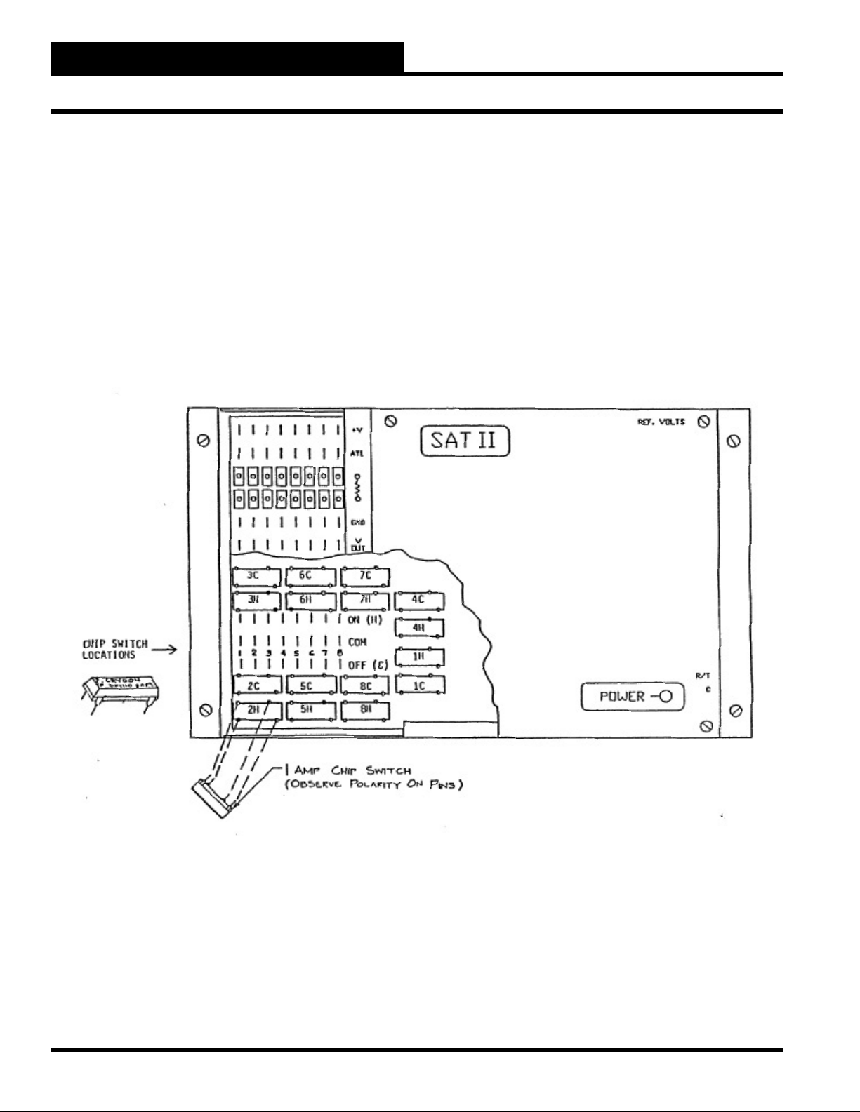
SAT II Chip Switches .................................................5-15
SAT II V-Out (DAC) Modules .....................................5-16
Binary Input Board ....................................................5-17
V-Out Binary Interface Board ...................................5-18
Proportional-Integral (PI) Output Board ..................5-21
Temperature Sensors ................................................5-24
Operator Interfaces
TOC-3
Page 6

WCC II Operator’s Guide
Table of Contents
TOC-4
Operator Interfaces
Page 7
WCC II Operator’s Guide
System Overview
INTRODUCTION: SYSTEM
OVERVIEW
____________________________________________________
The ECC/WCC II is a microprocessor based energy management
and temperature control system designed to minimize the energy
usage of a building and maximize the occupant comfort.The ECC/
WCC II system provides the building owner with a means of
monitoring and controlling building mechanical systems from one
central location. The ECC/WCC II system provides computerized
control of building mechanical systems, but requires no computer
experience to operate or program the system.
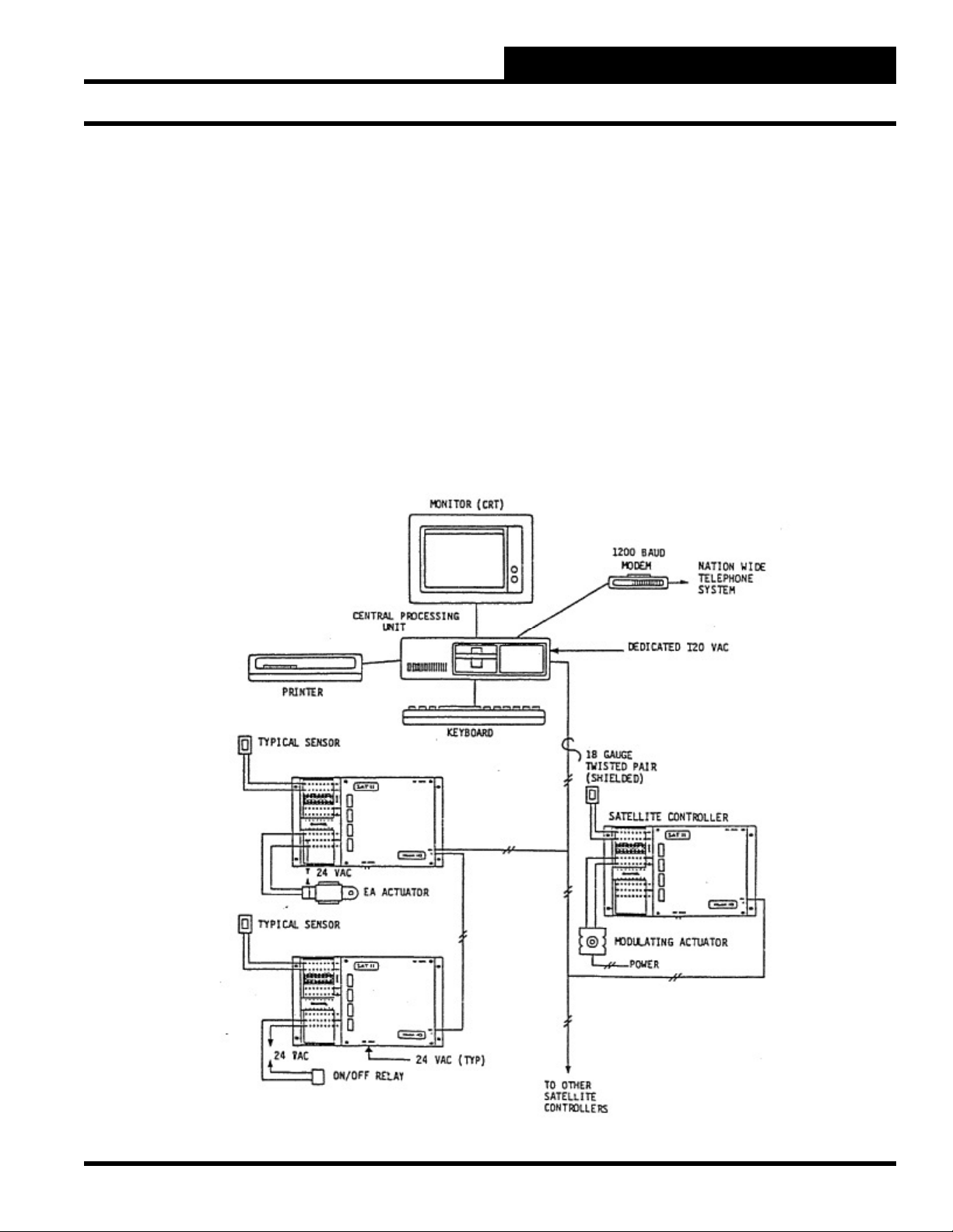
Diagram of WCCII System
The “front end” of the ECC/WCC II system consists of a personal
computer with custom communication boards. See Diagram that
follows. The computer is referred to as the Central Processing
Unit (CPU), and the computer, keyboard, monitor (screen), printer
(optional), and modem (optional) together are referred to as the
Operator Control Console. The CPU communicates with the
remote satellite controllers using a two-wire communication loop.
Operator Interfaces
I-1
Page 8

WCC II Operator’s Guide
System Overview
Operator Control Console
Components
The building operator monitors and controls the building
mechanical systems from one central location called the Operator
Control Console. The Operator Control Console consists of the
following components:
1. Central Processing Unit (CPU)
2. Keyboard
3. Monitor (CRT)
4. Printer (optional)
5. Modem (optional)
Central Processing Unit
A personal computer with custom communication boards acts as
the Central Processing Unit (CPU) which communicates with the
remote mounted satellite controllers via a two wire communication
loop.
The personal computer is dedicated to the ECC/WCC II system
and cannot be used for other functions. The use of hardware
accessories with the ECC/WCC II CPU that is not specifi cally
approved in writing by WattMaster Controls Group will void the
warranty on the ECC/WCC II system. The use of software other
than that furnished with the ECC/WCC II system may result in
system malfunction. WattMaster Controls Group is not responsible
for a system failure so generated.
Monitor
Note: We highly recommend that you only use the number
keys along the top of the keyboard while entering numeric
values and use the keypad ONLY for cursor control on the
ECC/WCC II system.
Printer
The on-site printer allows the operator to print status or schedule
summaries, a permanent record of entered programs, and trend
logging reports. The printer will automatically print alarms as they
occur, print operator ID as the user signs on and off the system,
and print any overrides that are entered.
Satellite Controller
The satellite controllers are fi eld mounted, microprocessor based
units which provide direct digital control of building mechanical
systems. The satellite controllers receive operating instructions
from the CPU, but once they are programmed, they have the
“brains” to monitor and control building mechanical systems
independently of the CPU. If communication from the CPU to
the satellite controllers is broken, the satellite controllers will
continue to control at programmable setpoints. In the event of a
primary power failure, the satellites will retain both their operating
instructions and accumulated data in battery backed memory.
The three versions of the satellite controller that will communicate
with the ECC/WCC II system are the SAT II, SAT II-A, and SAT
II-B.
The monitor resembles a television and displays computer data in
text on its cathode ray tube (CRT), or screen.
Keyboard
The keyboard is arranged like a typewriter to allow manual entry
of data and programs. We suggest that you fi rst become familiar
with the keyboard before attempting to operate the system. Refer
to the owner’s manual supplied with your computer for additional
keyboard information.
I-2
Operator Interfaces
Page 9

WCC II Operator’s Guide
System Overview
SAT II
Sensors and relays etc. are wired to the SAT II controller to allow
it to monitor and control loads directly. Each SAT II controller can
handle the following number of inputs and outputs:
8 analog or binary inputs
•
•
16 additional binary inputs
- 1 binary input board receives 8 binary inputs
- 2 binary input boards may be used with one
SAT II
8 analog outputs (0-15 VDC maximum range)
•
- 1 DAC module enables 4 analog outputs
- 2 DAC modules may be installed in SAT II
- Any or all of the 8 analog outputs may be
converted to binary outputs using 1 V-Out
to Binary board
- 1 chip switch is required for each binary
output
•
16 binary outputs
- 1 chip switch is required for each binary
output
SAT II-A
The SAT II-A is a version of the satellite controller that allows the
ECC/WCC II front end computer to communicate with remote
mounted Terminal Unit Controllers.
The Terminal Unit Controller (TUC) is a microprocessor based
device which can be used to control terminal units such as pressure
dependent variable air volume (VAV) boxes, pressure dependent
fan power boxes, fan coil units, heat pumps etc. The TUC can be
used as a stand-alone controller, or the TUC can be used with the
ECC/WCC II system.
The TUC accepts an input from a room temperature sensor to allow
it to monitor the space temperature and when used with the SA
(Stepper Actuator) actuator, provides pressure dependent control
of the primary air damper on terminal units such as variable air
volume boxes, constant fan power induction units, and intermittent
fan power induction units. The SA Actuator is not an integral
part of the TUC and must be ordered and purchased separately.
The TUC can also have three relay outputs to provide control of
the fan and fi rst and second stages of heat on fan terminal units,
or to control the fan, compressor, and reversing valve on a heat
pump. The TUC can also provide an output to control two 24 VDC
solenoid air valves to obtain “feed” and “bleed” type control of
pneumatic controlled devices. The TUC is generally mounted at
the terminal unit (i.e. VAV box, heat pump, etc.).
When the TUC’s are to be used with the ECC/WCC II system,
a type SAT II-A satellite controller is required as the interface
between the Central Processing Unit (CPU) and the Terminal Unit
Controller (TUC). The SAT II-A is a special version of the satellite
controller, and its only purpose is to interface with the TUC’s. Up
to 32 TUC’s can be connected to one SAT II-A using a 3-wire,
shielded cable. The TUC’s are wired to the SAT II-A in a “daisy
chain” arrangement. That is to say, the 3-wire cable does not have
to be run from each TUC back to the SAT II-A. The 3-wire cable
is run from the SAT II-1 to the nearest TUC and the 3-wire cable is
extended from that TUC to the next.
TUC Input/Output Features
The fi ve versions of the pressure dependent TUC are shown in the
table that follows:
Model TUC Description
TUC-R 3 Relays with 2 amp, 24 Volt SPDT Contacts
TUC-A Stepper Motor Actuator Output
TUC-AR Stepper Motor Actuator Output & 3-24 Volt
SPDT Relays
TUC-P Pneumatic Output
TUC-PR Pneumatic Output & 3-24 Volt SPDT Relays
Note: The SA actuator and solenoid air valves must be
ordered and purchased separately.
SAT II-B
The SAT II-B is similar to the SAT II-A, only the SAT II-B
communicates with up to 32 TUC-VR’s.
The TUC-VR is a velocity resetting (pressure independent)
controller for use with variable air volume (VAV) terminal units.
The TUC-VR mounts on the VAV box and communicates with
the front end ECC/WCC II through a SAT II-B. The TUC-VR
provides precise direct digital control of the following types of
VAV terminal units:
1-Cooling Only
2-Cooling/Staged Electric Reheat
3-Cooling/Time Proportioning Electric Reheat
4-Cooling Proportional Reheat Valve
5-Parallel Fan Powered/No Reheat
6-Parallel Fan Powered/Staged Electric Reheat
Operator Interfaces
I-3
Page 10

WCC II Operator’s Guide
System Overview
7-Parallel Fan Powered/Time Proportioning Electric Reheat
8-Parallel Fan Powered/Proportional Reheat Valve
9-Series Fan Powered/No reheat
10-Series Fan Powered/Staged Electric Reheat
11-Series Fan Powered/Time Proportioning Electric Reheat
12-Series Fan Powered/Proportional Reheat Valve
System Features
Standard Software
The following features are part of the standard ECC/WCC II
software package:
User Designed Screens
•
Schedule Override by Room Number (or name)
•
Point Involvement Summary
•
Data Copy Routine
•
Message Screen
•
Math Operators/Enthalpy Logic
•
User Confi gurable Look Up Tables
•
Sliding Window Averaging of Values
•
Accumulation of Values
•
Trend Logging features which include:
•
Analog Trend (with graph)
Analog Peak
Change of State
Run Time
Proportional Reset (with graph)
•
Auto-Scan and Print Routines
•
Multiple Energy Consumption Tables
•
Remote monitoring
•
Local or remote override capability
•
Remote read and reset
•
Automatic print-out and call-out on alarm
•
16 operator codes with 4 levels of access
•
365 day timeclock with automatic daylight savings
•
time changeover
32 week schedules and 18 holiday schedules
•
8 alarm levels
•
Temperature control with automatic temperature
•
setback
Adaptive optimized start and optimized stop
•
Duty cycling
•
Timed overrides
•
Demand limiting
•
Dead band spreading
•
Lighting control
•
Optional Enhanced Color Graphics
The Enhanced Color Graphics option allows the ECC/WCC II
system to display up to 60 color graphic pictures in the same front
end computer that acts as the ECC/WCC II CPU. The color graphic
pictures can be drawn using nearly any color graphics package,
and once the picture is displayed on the screen, a “snap-shot” of
the picture is captured and used as the background picture on the
Enhanced Color Graphics Screen. Dynamic analog and binary
values are then placed on the screen to allow the user to see actual
temperatures, status, etc. in the proper place on the picture.
When ordering the Enhanced Color Graphics option, a WCC II with
a 20MB hard disk, an EGA card, and color monitor is required as
the front end computer along with the additional Enhanced Color
Graphics software and a graphics package such as PC Paintbrush.
Optional Tenant Override
The Tenant Override Feature allows the occupants in the building
to call the ECC/WCC II system on the telephone and cause the
lights and/or heating and/or cooling equipment to control according
to their occupied (daytime) control scheme. The system has the
capability of overriding the control for 500 zones.
The ECC/WCC II system will “talk” to the tenant using an artifi cial
voice, and the user instructs the ECC/WCC II system by pressing
the numbers on the telephone.
A summary report of which tenants used the telephone override
system is available for billing purposes. A separate telephone line
is required for the Tenant Override Feature.
System Size
The central processing unit is capable of communicating with up
to 240 SAT II controllers. The front end ECC/WCC II considers
each SAT II-A or SAT II-B as 4 SAT II controllers. The equivalent
number of satellite controllers must be under 240.
A system with 240 satellite controllers is capable of handling up to
11520 points, a point being a hard wired input or output.
Modular Construction
Equipment cost is reduced because the system, including the satellite
controllers, is modular. Only the number of satellite controllers
required for the job are purchased, and only the required number of
outputs are purchased for the satellites. Installation cost is reduced
because “global” information gathered at one satellite can be shared
with other satellites, eliminating costly intermediate controls.
I-4
Operator Interfaces
Page 11

WCC II Operator’s Guide
Section 1: General Instructions
SECTION 1: GENERAL
INSTRUCTIONS
____________________________________________________
“Where To Find” Features
The following is a list of commonly used ECC/WCC II features
and the screens you should access to use them.
FEATURES SCREEN
Alarms
“Call-Out-On-Alarm”
Call “Both” or “Either” Phone
Number
Input Telephone Numbers
Select Remote Printer
Clear (Acknowledge) Alarms Alarm Summary
Disable Local Printer Utility-Sys Par II
Set Alarm Limits
Analog Inputs
Run Time
Global Analog Values
Global Binary Values
View Alarms
All Alarms (Except Globals)
Global Alarms
Daylight Savings Time Adjustment System Parameters
Demand Limiting Shed/Restore
Delete Back-Up Files Utility-File Mgmnt
Monitor Analog Inputs
(Temperature/Pressure etc.)
Find Highest or Lowest Building
Tem p
Find Average Building Temp
Present Value
Trend Logs
Monitor Binary Inputs (air fl ow switch etc.)
Present Value
Trend Log.
Password Entry
Assign Operator Access Codes
“Sign-On”
“Sign-Off”.
Print Screens Automatically Special Keys
Rebuild Satellite Tables Utility-Rbld Sat
Schedules
Change Schedules Permanently.
Holiday Schedules
Utility-Sys Par II
System Parameters
System Parameters
Analog Input Screen
Trend Logs
Global Analog
Global Binary
Alarm Summary
Global Summary
Global Analog-Sort
Global Analog-Avg
Analog Input Summary
Analog Trend
Logic Switches
Change of State
Sys Par/Oper Codes
System Parameters
Secure Screen
Week Schedules
Holiday & Week Sch
FEATURES SCREEN
Setpoints
Change Setpoints - Satellite
Change Setpoints - TUC
Sequence Satellites After a Power Outage Satellite Summary
Time and Date Modifi cations System Parameters
Control Outputs
EA Driver & TUC
ECC/WCC II Routine Maintenance
The following maintenance items should be performed on a regular
basis:
Service Item As
Req’d
Blow out
keyboard
Blow out CPU
assy
Check all
external cable
connections
Test/Verify
U.P.S.
operation
Clean display
screen
Dim display
screen
Clean fl oppy
drives
Tes t fl oppy
drives
Test CPU
memory
Test display
monitor
Test printer
Test modem
(system’s
ability to
answer
incoming
calls)
Test modem
(system’s
ability to callout-on-alarm)
Every WkEvery MoEvery
XX
XX
XX
XX
*X
XX
3 Mo
Every
6 Mo
X
X
X
X
X
Every
12 Mo
X
X
Operator Interfaces
1-1
Page 12

WCC II Operator’s Guide
Section 1: General Instructions
Service Item As
Req’d
Delete“backup” (*.bak)
fi les
Make “backup” copies of
disks
Check disks
for available
space to
prevent
overfi lling the
disk
Check loop
connection on
rear of CPU
Save satellite
data to disk
Rebuild all
satellite and
global tables
Test satellites’
local-set
capability
Test satellites’
battery (or
capacitor)
Check/Clear
satellite
communication errors
on
Satellite
Every WkEvery MoEvery
3 Mo
XX
XX
XX
XX
X
XX
Summary
Screen
Run loop test X
Check/Reset
trend logs
View/Clear all
alarms
Cycle power
to CPU to
verify correct
system re-start
after a power
outage
XX
XX
Every
6 Mo
Every
12 Mo
ECC/WCC II Software Version List
The ECC/WCC II software is updated periodically to include more
features. The two fi les that change as the ECC/WCC II system is
upgraded are the WCC2 fi le and the BACKTASK fi le. When a
WCC II fi le is installed in a system, the BACKTASK fi le may need
to be changed also. The following list shows the WCC2 version
numbers and the BACKTASK fi le that must be used with it.
Note: You can see the present WCC2 and BACKTASK
version used by the system by looking at the lower left hand
corner of the Main Menu Screen.
X
WCC2 Version Minimum BACKTASK Version
1.47* 1.1B
1.48* 1.1B
1.49* 1.1B
1.52 1.22
1.54 1.24
X
X
1.6A 1.24
1.6B 1.24
1.63 1.24
1.64 X.2B**
1.65 X.2BB**
1.67 1.2E
1.68 1.2E
1.69 1.4A
1.70 1.4A
1.71 1.4B
1.72 1.4B
1.74 1.4D
* These versions of software require the front end computer to
have 448K of RAM memory; later versions require 640K.
X
**X = 1 to 3
1 = IBM PC or XT
2 = IBM XT 286
3 = 3 satellite system
* Set the screen’s intensity to the lowest setting when the system
is not being used.
1-2
Operator Interfaces
Page 13
WCC II Operator’s Guide
Section 1: General Instructions
Recommended Data Entry Procedure
When setting up an ECC/WCC II system, the screens can be
programmed in any order. However, you may fi nd it easier to
follow this sequence:
Make back-up copies of the disks
1.
System Parameter Screen
2.
Utility Screen - Rebuild Satellite Tables
3.
Satellite Summary Screen
4.
On/Off Units Messages Screen / Alarm Message
5.
Screen —Enter the On/Off messages, units of
measure messages, and alarm messages, and then
print the messages using <Print Screen>. Keep a
copy of these messages handy while entering data
on the remaining screens
Week Schedule Screens
6.
Holiday Screen
7.
Analog Input Screens
8.
Logic Switch Screens
9.
Control Output Screens
10.
Analog Inputs
An analog input is a numerical value (signal) sent to the SAT II
controller to allow monitoring of space temperatures, duct pressures
etc. The SAT II controller can accept 8 analog inputs which
are named, A1-A8. (Note: A1-8 may be either analog or binary
inputs.) On certain screens (such as Global Analog Screens), you
must indicate the satellite controller number along with the channel
on the satellite controller. For example, 12A2 means analog input
number 2 on satellite controller #12.
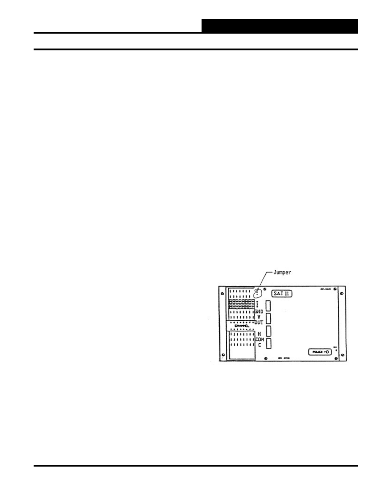
The analog inputs are usually wired to the “+V” and “ATI” (Actual
Temperature In) terminals on the SAT II controller (three wire
sensors are wired to the “GND” terminal also.) The “+V” terminal
on channels 1-7 are a 12 VDC power source. The “+V” terminal
on channel 8 provides either 12 VDC or 18 VDC depending on
the position of the jumper under the cover near channel 8. To get
12 VDC from the “+V” terminal on channel 8, the jumper must
connect the A and B terminals. To get 18 VDC, the jumper must
connect the B and C terminals.
A 20 mA sensor can be used on up to 5 channels on the SAT II
controller. The total current for all 8 analog inputs must be kept
under 115 mA.
TUC Screens
11.
Analog Output Screens
12.
Analog Global Screens
13.
Binary Global Screens
14.
Optimal Start Screens
15.
Shed/Restore Screens
16.
Duty Cycle Screens
17.
Proportional Reset Screens
18.
Energy Consumption Screens
19.
Trend Log Screens
20.
Custom Screens/Enhanced Graphic Screens
21.
Special Keys Programs
22.
Save Satellite Data to Disk
23.
Make Back-Up Copies of the Disks
24.
Operator Interfaces
1-3
Page 14
WCC II Operator’s Guide
Section 1: General Instructions
Binary Inputs
A binary input is an On/Off (dry contact closure) signal sent to
the SAT II controller to allow monitoring of air fl ow switches,
switch settings, etc. The SAT II controller comes standard with
16 small toggle switches on its front panel labeled, L1-L16 which
are in effect manually controlled binary inputs. The ECC/WCC II
monitors the On/Off status of these switches and can control and/or
alarm based on the position of these switches. The binary input
board(s) allow the manual toggle switches to be replaced with a
terminal strip which accepts wiring from remote mounted binary
input devices.
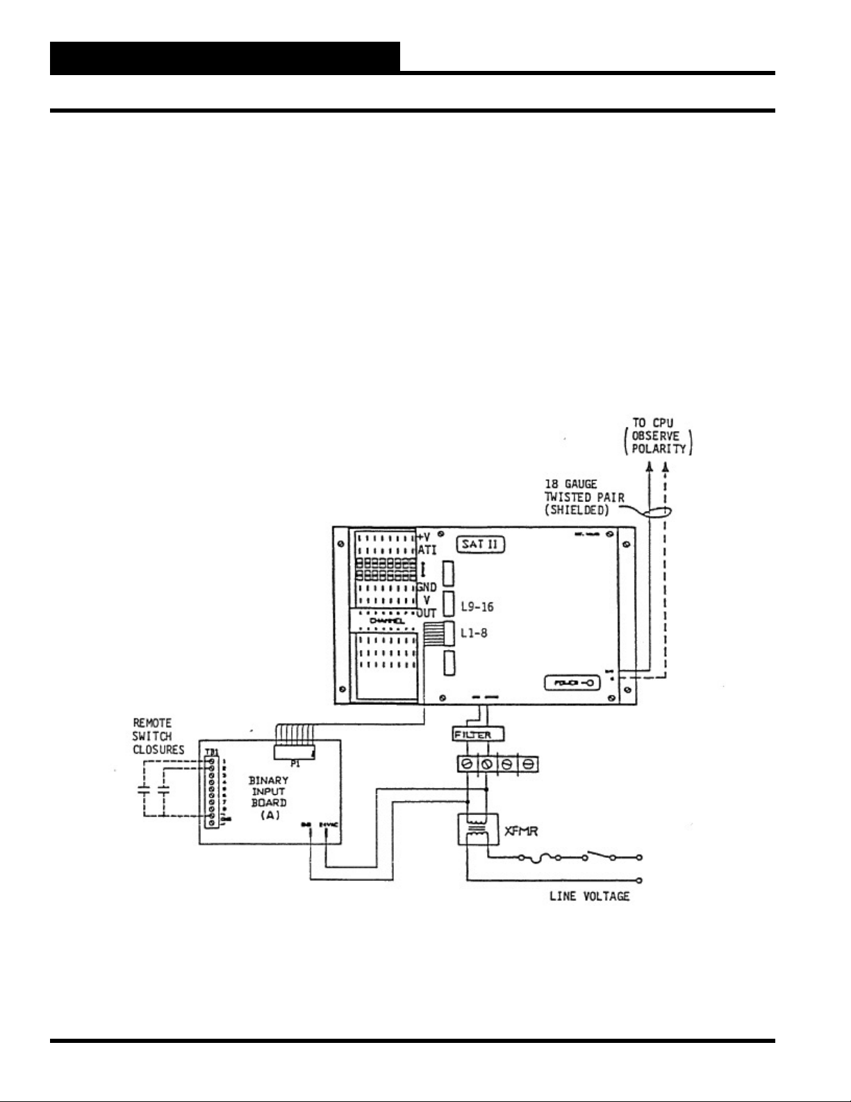
The SAT II controller has two sets of 8 small toggle switches on its
front cover labeled L1-L16. Switches L1-L8 are housed together in
one module, and switches L9-L16 are housed together in another
module. One module of switches is removed for each binary input
board and replaced with a ribbon cable which connects the binary
input board to the SAT II controller. The binary devices to be
monitored are then wired to the terminal strip of the binary input
board. The binary input board requires a 24 VAC power supply.
1-4
Operator Interfaces
Page 15
WCC II Operator’s Guide
Section 1: General Instructions
Analog Outputs
An analog output is a variable DC voltage signal sent from the
satellite controller used for proportional control of devices with
modulating actuators. The analog outputs are wired to the “V-Out”
and “Gnd” terminals on the SAT II controller and are named P1P8. The P stands for Proportional Output.
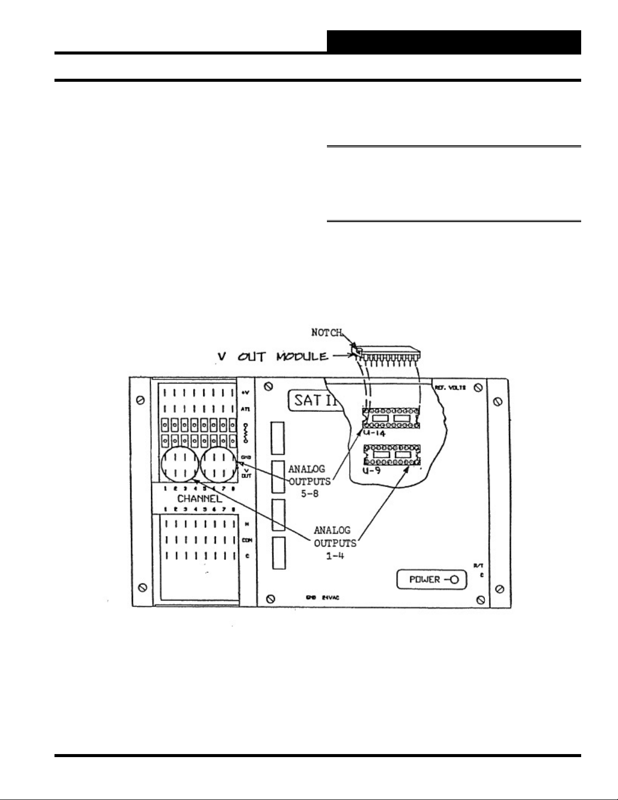
The SAT II controller has the capability of providing 8 analog
output signals which have a maximum range of 0-15 VDC. If the
analog outputs are to be used, V-Out modules must be purchased
and are fi eld installed. One V-Out module is required for 4 analog
outputs, and two V-Out modules can be installed in one satellite
controller to allow one satellite controller to provide up to eight
analog outputs.
Each analog output has a limit of 15 mA. The total current output
of all 8 analog outputs must be kept under 115 mA.
Note: Later versions of the satellite controllers require two
modules for each set of four analog outputs. On these models,
sockets U-9 and U-10 activate outputs 1-4, and sockets U-11
and U-14 activate outputs 5-8.
Operator Interfaces
1-5
Page 16
WCC II Operator’s Guide
Section 1: General Instructions
Binary Outputs
A binary output on the SAT II controller is the electronic equivalent
of a relay contact which is used to complete a 24 VAC circuit to
activate on/off devices such as relays, 2-position valves, etc. The
binary output contacts cannot be used to complete a DC voltage
circuit; they will work with AC circuits only. The binary output
terminals are labeled H, COM, and C.
The SAT II controller is capable of providing 16 binary (on/
off) outputs. Each binary output requires 1 chip switch which is
purchased separately and is fi eld installed.
The terminals for the binary outputs are found at the lower left hand
corner of the SAT II controller. The “COM” to “H” contacts are
referred to as K1h-K8h. The “COM” to “C” contacts are referred
to as K1c-K8c.
1-6
Operator Interfaces
Page 17
WCC II Operator’s Guide
Section 1: General Instructions
Point Addresses
A Point Address uniquely identifi es a point within the ECC/WCC
II system. All point addresses have an associated “analog” or
“binary” value. The term “analog” simply means a value which
is represented by a number (such as room temperature, duct static
pressure, etc.). The term “binary” means the value is represented by
one of two conditions, ON or OFF. An input is a signal sent to the
ECC/WCC II system, and an output is sent from the ECC/WCC II
system. Therefore, room temperature is an analog input, fan status
is a binary input, and controlling a fan relay is a binary output.
In addition to the inputs and outputs that are wired to the SAT
II controllers, there are several software point addresses within
the system. For example, the ECC/WCC II system has 32 week
schedules. This means that a separate day/night schedule can be
assigned to 32 different areas of the building.
For example, assume that you have three different areas in a
building that have different schedules as shown in the following
table.
Area Occupied Time
Week Schedule #1 1st Floor West 8:00 am - 5:00 pm, M-F
Week Schedule #2 1st Floor East 7:00 am - 7:00 pm, M-F
Week Schedule #3 2nd Floor 9:00 am - 4:00 pm, M-Th
Week Schedule #1 is named W1, and the value of W1 will be On
between 8:00 am and 5:00 pm, Monday through Friday, etc.
The Name column in the table that follows is the name that you
should use when specifying a point address to the system. The “n”
is where a “point number” for the point address is to be entered.
Name Description Value
TnC Trend Logging Change of State None
TnA Trend Logging Analog Trend None
TnP Trend Logging Analog Peak None
Ln Logical Input On/Off
Wn Week Schedules On/Off
Sn Optimal Starts On/Off
GBn Binary Globals On/Off
GAn Analog Globals Analog
Constant Point Addresses
The following list shows several point addresses within the
system that are always available for use on many of the data input
screens.
Name Description Associated Data Type
0 Logical Zero Always Off
1 Logical One Always On
//// Logical Null Ignored
. . . . Logical Off Always Off/Not Used
Note: When a point option is not required, replace the default
value (/ / / /) with either a zero (0) or dot (. . . .) to force the
system to realize that the option is always OFF. If the slashes
are not replaced, the system will ignore that input and the
system can, in rare cases, see the slashes as being ON.
Table of Point Addresses
Name Description Value
Cn Comparator (See analog input
screen binary setpoint)
An Analog Inputs Analog
Pn Analog Inputs Analog
KnH Control Outputs
(H Contacts)
KnC Control Outputs
(C Contacts)
RnA Data Registers (a) Analog
RnB Data Registers (b) Analog
TnR Trend Logging Run Time Analog
Operator Interfaces
On/Off
On/Off
On/Off
Name Description
Analog 0 Initiates a 0 (zero) value
TIME Current Time (in HH:MM format)
TIMEB Current Time (in minutes-since-midnight format)
NEWSEC New Second
NEWMIN New Minute
NEWHR New Hour
NEWDAY New Day
NEWMON New Month
1-7
Page 18

WCC II Operator’s Guide
Section 1: General Instructions
Time & TimeB
These logical addresses are the actual time on HH:MM (TIME) and
minutes-since-midnight (TIMEB) formats. They are considered
analog values and have value ranges of 0000 to 2359 (TIME), and
0000 to 1439 (TIMEB).
Typical application of these logical addresses includes use in
the Dual Limit mode, allowing such modes of control as “OnBetween-Times” and “Off-Between-Times.”
NEWSET, NEWMIN, NEWHR, NEWDAY, & NEWMON
These logical addresses are considered binary values and are based
on real-time. They have a pulse-type nature in that each of these
addresses has a value of one (or ON) for one second after the
occurrence of the specifi ed event. After the one second ON period
has elapsed, the value returns to zero (or OFF).
These addresses have several uses throughout the system. One
example would be the generation of a variable duty cycle output.
When used in conjunction with the separate “Minimum ON/OFF”
timers, these addresses can achieve cycles of from one second to
several days with a wide range of cycles.
Examples of “point addresses” within the system:
Data Registers
The ECC/WCC II system has some capabilities built into the
software that are very helpful, and you should be aware of them.
There is a Data Register associated with each of the Control
Output Screens. A Control Output Screen allows the user to tell
the satellite controller when to open and close the binary output
contacts. A Control Output Screen can be a Time Clock, EA Driver,
or Dual Limit Mode Screen.
Time Clock
When the binary output contact on the satellite controller is
controlled by a Time Clock Screen, the contact opens and closes
based on time only. For example, a Time Clock Screen can be used
to run a water circulating pump from 8:00 am to 5:00 pm, Monday
through Friday. Each Time Clock Screen has a Data Register
associated with it.
The Data Register is an analog value which is the time in seconds
since the satellite controller binary output contact closed. Assume
the water circulating pump is controlled by satellite controller
contact K1h. That is to say, the “COM” to “H” contact on channel
1 of the satellite controller closes to complete a 24 VAC signal to
run the pump.
Name Description
GA12 Global Analog #12
135A5 Satellite #135, Analog Input #5
A5 Analog Input #5, Current Satellite
W12 Week Schedule #12
S27 Optimal Start #27
C1 Setpoint Comparator on Analog Input #1
K1h
14P3
When K1h is ON, the chip switch within the
satellite controller which connects the electrical
path between the “H” and “COM” terminals on
channel 1 of the satellite controller is closed.
When K1h is OFF, the circuit is open.
Satellite #14, Analog Output #3.
The Data Register for a Time Clock Screen is named RnA or RnB.
R stands for data register, n refers to channel 1-8 of the satellite
controller, A means the “COM” to “H” contact, and B means the
“COM” to “C” contact. Therefore, the Data Register for contact
K1h is R1A. As contact K1h closes, the Data Register for contact
Klh (R1A) starts recording time in seconds. That is to say, the value
of R1A is the time in seconds since contact K1h closed.
RnA = Time in seconds since COM to H contact closed
RnB = Time in seconds since COM to C contact closed
The Data Register for a Time Clock Screen might be used to
start one piece of equipment after another has been started. For
example, assume we want to start an air handler two minutes after
the water circulating pump starts. The pump would be controlled
by a Time Clock Screen as mentioned above. The air handler would
be controlled using a Dual Limit Screen. The analog input value
for the Dual Limit Screen would be R1A, which is time in seconds
since the pump started. The Dual Limit Screen is set up to close the
contact for the air handler when the value of R1A is between 120
seconds and infi nity.
1-8
Operator Interfaces
Page 19

WCC II Operator’s Guide
Section 1: General Instructions
EA Driver
The EA Driver Mode is “3-point fl oating” control. For example,
assume that the control outputs on channel 2 of the satellite
controller are used to control a Tempmaster VAV box using the
EA Driver Mode. When the space needs heat, the “COM” to “H”
contacts on the satellite controller will close to drive the damper in
the VAV box to the closed position. When the space needs cooling,
the “COM” to “C” contact on the satellite controller will close to
open the damper in the VAV box.
There are two Data Registers associated with an EA Driver Screen.
The value of the fi rst Data Register is equal to the setpoint entered
on the EA Driver Screen and is referred to as “RnA.” The value
of the second Data Register is equal to the difference between the
setpoint and the actual temperature and is referred to as “RnB.”
“R” stands for data register, and “n” refers to channel 1-8 of the
satellite controller.
RnA = Setpoint
RnB = Difference between Setpoint and Measured Value (error)
For example, assume that the setpoint for the room in question
is 72 °F, and the actual temperature is 70 °F. The value of Data
Register R2A (setpoint) is 72 °F, and the value of Data Register
R2B (error) is -2 °F, since the actual space temperature is 2 °F
below the setpoint.
The Data Register could be used to turn on a second stage of heat
whenever the space temperature falls 2 °F below setpoint. Assume
that the second stage of heat is a heating coil which is energized
when satellite controller contact K3h is closed. A Dual Limit Screen
is used to control contact K3h. Data Register R2B is entered as
the analog input value for the Dual Limit Screen. When the value
of R2B is -2 or less (the space temperature is at least 2 °F below
setpoint), contact K3h closes to turn on the second stage of heat.
The Data Register for a Dual Limit Screen is named “RnA” or
RnB.” “R” stands for data register, “n” refers to channel 1-8 of the
satellite controller, “A” means the “COM” to “H” contact, and “C”
means the “COM” to “C” contact. Therefore, the Data Register for
contact Klh is R1A.
RnA = Difference between Setpoint and Measured Value (COM
to H)
RnB = Difference between Setpoint and Measured Value (COM
to C)
The Dual Limit Screen has two setpoints, the high limit and the low
limit. Since the Data Register is the difference between the setpoint
and the actual temperature, you have to “tell” the system what you
are considering the setpoint to be. Therefore, the Data Register is
measured from either the “Midpoint” or “Nearest Limit” of the
setpoints, depending on how the Dual Limit Screen is set up.
For example, assume that a Dual Limit Screen is used to control a
heat pump compressor to have the compressor off if the space is
between 70 and 74 °F. If the space temperature is below 70 °F, the
compressor will be on for heating, and if the space temperature is
above 74 °F, the compressor will be on for cooling. Assume the
actual space temperature is 76 °F.
The Data Register can be measured from either the “Midpoint”
or the “Nearest Limit.” If the Data Register is measured from the
“Midpoint,” the value of the Data is 4 °F.
Low Limit High Limit
70 72 74 76
4 Deg
Midpoint Actual Temperature
Data Register
Dual Limit
When the binary output contact on the satellite controller
is controlled by a Dual Limit Screen, the contact opens and
closes based on how the analog input value compares to a pair
of setpoints. There is one Data Register for each contact on the
satellite controller which is controlled by a Dual Limit Screen. The
value of the Data Register is the difference between the setpoint
and the actual temperature.
Operator Interfaces
Difference between actual temperature and the “Midpoint” of the
setpoints = 4 °F, and therefore, the value of the Data Register is 4
°F.
If the Data Register is measured from the nearest limit, the value of
the Data Register is 2 °F.
Low Limit High Limit
70 74 76
2 Deg
Nearest Actual
Limit Temperature
Data Register
1-9
Page 20

WCC II Operator’s Guide
Section 1: General Instructions
Alarm Print-Out and Call-Out
The ECC/WCC II will automatically print alarms as they occur
on a local printer or will call out over standard telephone lines
and report the alarms to a remote printer. There are eight different
alarm types or alarm priorities. The fi rst fi ve alarm types can “callout”; each of these fi ve alarm types can call a primary and alternate
number.
The following is a sample of the ECC/WCC II print-outs:
-----------------------------------------------------------------------------------------
ECC/WCC II SYSTEM ID: *** TEMPERATURE INDUSTRIES, INC. *** 14:36 10/08
ALARM: ANALOG LIMITS
SAT #: 1 [SCIENCE RM] Input: 1 went into alarm at 14:36 on 10/08. High: 80.6 Deg F
low: ****** Deg F Class: 4
OPERATOR LOG-ON
Operator 33333 logged-on locally at 14:37 on 10/08 [Pswd Level: 3]
ALARM: RUN-TIME
SAT #: 1 [GYM FAN] Point: 5 went into alarm at 14:39 on 10/08. [OIL BEARINGS] Value:
501 Hours Class: 3
OPERATOR LOG-OFF
Operator 33333 logged-off locally at 14:39 on 10/08 [Pswd Level reset to 0]. (Logon
time: 0 hours 2 minutes)
OPERATOR LOG-ON
Operator JOHN logged-on locally at 14:40 on 10/08 [Pswd Level: 3]
OVERRIDE
Override for W1 entered at 14:40 on 10/08. Start: 14:40 on 10/08 End: 18:40 on 10/08
Override value: OFF
OPERATOR TIME-OUT
Operator JOHN timed-out locally at 14:43 on 10/08 [Pswd Level reset to 01]. (Logon time:
0 hours 3 minutes)
-----------------------------------------------------------------------------------------
1-10
Operator Interfaces
Page 21

WCC II Operator’s Guide
Section 1: General Instructions
Analog Alarm Limit
Each analog input can have a low and high limit assigned to it
on the Analog Input Screen. If the value of the analog input falls
below the low limit or rises above the high limit, the system
automatically generates an alarm. For example, assume that the
analog input in question is a room temperature sensor located in
an offi ce space. If the space temperature falls below 68 °F or rises
above 80 °F during the occupied period, we want an alarm to print
on the printer. To set up the alarm limits, fi rst sign on by accessing
the System Parameter Screen and entering your password. An
access level of 1 or greater is required to enter or change alarm
limits. After you are signed on, return to the Main Menu and place
the cursor over “ANALOG INPUT” and press <RETURN>. An
Analog Input Screen similar to what is shown below should come
into view:
-----------------------------------------------------------------------------------------
Satellite #1 ANALOG INPUT #1
Description: RM 101 Type: Analog
Pattern for values associated with this input: xxx.x
Units @ 0% scale: 0.0 Deg F Units of Measure Message #: 1
@ full scale: 100.0 Deg F Filter Time Constant: 8 seconds
The alarm limits along with the alarm type and alarm message
numbers are assigned on this screen (see the Analog Input Screen
section of this guide on page 3-9 for more information). If the
space temperature drifts out of the entered alarm limits, the system
will automatically generate an alarm. For example, assume that the
space temperature rises above the high limit value of 80 °F. Alarm
message #1 (High Temperature) along with the time and date of the
alarm and the high peak value of the room temperature will appear
on Analog Input Summary Screen and the Alarm Summary Screen.
Within one minute from the time the alarm appears on the screen, it
will automatically be printed on the local printer. (To acknowledge
alarms, use the <Control-A> function described in the Help Screen
(page 3-1), Analog Input Summary Screen (page 3-7), and Alarm
Summary Screen (page 3-36) sections of this guide.)
-------------------ALARMS--------------------
Controlled by: W1 Limits Low High
Alarm Type: 1 On 68.0 80.0 Deg F
Alarm Message #’s: Low 2 High 1 Off 50.0 90.0 Deg F
Alternate Limits selected by:.... On (alt) 0.0 0.0 Deg F
Off (alt) 0.0 0.0 Deg F
Limit overlap time
after control change: 20 Minutes Local set 55.0 90.0 Deg F
--------------------BINARY SETPOINT---------------------- OFF Above 0.0 Deg F On Message #: 0
OFF Below 0.0 Deg F Off Message #: 0
Home for menu
-----------------------------------------------------------------------------------------
Operator Interfaces
1-11
Page 22

WCC II Operator’s Guide
Section 1: General Instructions
Run Time Alarm
The ECC/WCC II system also has the capability of alarming if
the total ON time of a binary (on/off) value has exceeded the
run time alarm limit. To assign a run time alarm limit, fi rst sign
on by accessing the System Parameter Screen and entering your
password. An access level of 2 or greater is required to enter or
change alarm limits. After you are signed on, return to the Main
Menu and place the cursor over “TREND LOGS” and press
<RETURN>. The Trend Log Summary Screen should come into
view. To access a Run Time Trend Logging Screen, use the arrow
keys to place the cursor (>) by the desired run time point, and press
<RETURN>. The following screen should come into view:
-----------------------------------------------------------------------------------------
Satellite # 1 TREND LOGGING # 1 of Type: RUN TIME
Records total ON time Starting at : *:* on */*
for K1c Fan # 1 Reset by: L16 being ON
Alarm Type: 6
Alarm Message #: 7
In this example screen, we are recording the total “ON” time of
contact Klc (COM to C contact closure) on satellite controller
#1. When contact Klc is closed, or “ON”, Fan #1 runs. Run time
recorder #1 records total accumulated run time of the fan. Alarm
message #7 (Grease Bearings) will automatically appear on the
Alarm Summary Screen when the total accumulated run time of
the fan exceeds 500 hours. Within one minute after the alarm
appears on the screen, it will automatically print out on the local
printer. (See the Alarm Summary Screen section, page 3-36, for
information about how to acknowledge a run time alarm, and see
the Run Time Trend Logging Screen section, page 3-32, of this
manual for information about how to reset the accumulated run
time to zero.)
-
Current run time: 250 Hours Alarm Limit: 500 Hours
Home for Menu
-----------------------------------------------------------------------------------------
1-12
Operator Interfaces
Page 23

WCC II Operator’s Guide
Section 1: General Instructions
Satellite Fail Alarm
If the Central Processing Unit loses communications with a satellite
controller, a Satellite Alarm will print on the printer showing which
satellite is out of service and the time and date of the alarm.
Operator Sign On/Off
The ECC/WCC II system will automatically print the operator ID,
time, and date when an operator signs on or off the system. The
message will also indicate the password level of the operator and
if he or she signed on/off locally or remotely. When the operator
signs off, the total amount of time the operator has been signed on
the system will also be printed.
Manual Overrides
When the operator uses the Override Screen to force a point to
another value, a message will be printed indicating what was
overridden along with the time and date of the override.
To utilize the “call-out” on alarm feature, a 1200 baud Hayes
compatible modem is required at the on-site ECC/WCC II
computer, and a 1200 baud Hayes compatible modem and an IBM
graphics compatible printer, custom confi gured with a high speed
serial adapter is required at the remote site.
System Re-Boot
When the system is re-booted or restarted by either shutting the
computer off and then turning it back on or using <Ctrl> <Alt>
and <Del>, a message is shown on the printer showing the time
and date of the re-boot.
Hardware Requirements
The ECC/WCC II print routine is a standard software feature, and
the standard CPU has all of the hardware items required to support
a local printer. If local print-out is desired, an Okidata 182A, IBM
compatible, parallel printer with a standard IBM compatible cable
is recommended. We cannot offer trouble-shooting support if other
printers are used.
The local printer must be a parallel printer as opposed to a serial
printer. The ECC/WCC II CPU has a parallel and a serial port for
data output. The difference between a parallel and serial port is the
way in which data is transmitted. The only purpose a parallel port
serves is to send data to a printer on-site, and therefore the local
printer must be a parallel printer.
Operator Interfaces
1-13
Page 24

WCC II Operator’s Guide
Section 1: General Instructions
1-14
Operator Interfaces
Page 25

WCC II Operator’s Guide
Section 2: Initiating the System
SECTION 2: INITIATING THE SYSTEM
__________________________________________
The programs and data which are necessary to cause the personal
computer to act as the ECC/WCC II Central Processing Unit
are saved on a diskette(s) similar to the way music is stored on a
cassette tape.
Note: The personal computer also has special integrated
circuit boards, manufactured at WattMaster, which allow it to
act as the CPU.
After the satellite controllers have been installed and powered up,
the Central Processing Unit (personal computer) set up, and the 2wire communication line between the satellite controllers and the
CPU hooked up (see the Installation and Trouble Shooting Guide
for satellite controller start-up and check-out information), the
software needs to be loaded into the system. Loading the software
is a term which means that data on the diskettes is transferred into
the memory of the personal computer and/or into the memory of
the satellite controllers.
The personal computer used with the ECC/WCC II system may
have either two fl oppy disk drives or one fl oppy disk drive and one
hard disk drive. If the front end computer is an IBM system 2, the
fl oppy disks are 3.5 inch; otherwise, they are 5.25 inch disks. The
3.5 inch disks are sometimes referred to as micro fl oppy disks or
micros. The disk drive on the left hand side of the computer (Drive
A) always accepts a fl oppy disk. The right hand disk drive uses
either a fl oppy disk or a hard disk. If it is a fl oppy disk, then it is
referred to as drive B; if it is a hard disk then it is referred to as drive
C. Hard disks hold much more data than a fl oppy. A hard disk is
recommended on systems which have over 20 satellite controllers
and is required on systems which utilize Enhanced Color Graphics
or the Telephone Override Feature.
You should receive the following disks with an ECC/WCC II
system:
Dual Floppy Systems
“DOS Disk - Version 3.3”
“Drive A Operating Disk”
“Drive B Operating Disk”
“Drive A Back Up Disk”
“Drive B Back Up Disk”
Hard Disk Drive Systems
“DOS Disk - Version 3.3”
“Back Up Disk #1”
“Back Up Disk #2”
The DOS (Disk Operating System) Manual is shipped in the box
with the ECC/WCC II CPU (personal computer). You should
fi nd two disks in the back of the DOS manual; you need the disk
labeled “DOS”. The ECC/WCC II system will operate with DOS
2.1 or greater.
CAUTION: DOS 2.1 must be used on dual fl oppy systems
which have 5.25 inch disk drives. The DOS 3.3 fi le is too large
and will not allow enough room for the other ECC/WCC II
fi les.
If you have a dual disk system, “Disk A” will stay in Drive A of the
ECC/WCC II CPU (personal computer) and “Disk B” will remain
in drive B. If you have a “Hard Disk” system, the “Disk A” and
“Disk B” will be copies onto the hard disk (Drive C).
It is very important to make back-up copies of the disks after the
system has been “programmed” to control your building.
You can tell if your system has a hard disk by looking at the disk
drives on the personal computer. A disk drive that uses a fl oppy
disk has a door with a slot which allows you to insert and remove
the disk. The hard disk is permanently in the drive, and therefore
there is no door on the front of the drive. If your system has two
fl oppy disk drives, then it is referred to as a “ Dual Floppy” or a
“ Dual Disk Drive” system. If the disk on the right does not have a
disk drive door, then the disk in the right hand drive is a hard disk,
and the system is referred to as a “Hard Disk” or “Fixed Disk”
system.
Operator Interfaces
Dual Disk Drive Systems
If the ECC/WCC II CPU (personal computer) has two “fl oppy”
disk drives, then the following procedure should be followed to
load the software into the computer. Before you can load the ECC/
WCC II software, you need to have the following items:
1) “Drive A Operating Disk”
2) “Drive B Operating Disk”
2-1
Page 26

WCC II Operator’s Guide
Section 2: Initiating the System
Insert the ECC/WCC II “Drive A Operating Disk” into drive A
(left hand drive), the “Drive B Operating Disk” into drive B (right
hand drive) and “boot-up” the system.
If your computer is off: Turn the power on. Then close the
disk drive doors.
If your computer is on: Press and hold <Ctrl> and <Alt>.
Then press and hold <Del>.
After a few seconds the computer should read the data from the
disks, and it will automatically bring up the ECC/WCC II Main
Menu.
Note: As you program a system to control a building,
information is written on the disks. It is very important to
make back-up copies of the “Working” disks after the system
has been programmed to control the building.
Hard Disk Drive Systems
If the ECC/WCC II CPU (personal computer) is a “Hard-Disk”
system, the ECC/WCC II program is stored on the hard disk so
“booting-up” the system will cause the ECC/WCC II Main Menu
to appear on the screen.
If your computer is off: Open the drive A door and then turn
the power on.
If your computer is on: Press and hold <Ctrl> and <Alt>.
Then press and hold <Del>.
After a few seconds the computer should read the date from the
hard disk (drive C) and the ECC/WCC II Main Menu system
should eventually appear on the screen.
The hard disk can hold a vast amount of data which can accidentally
be erased or lost due to system malfunction, operator error, etc.
Therefore it is extremely important to make a back-up copy of
the data on the hard disk. As you program a system to control a
building, information is written on the disks. Therefore, back-up
copies of the hard disk should be made after the system has been
programmed to control the building.
Copying Disks
“ Backing-up” a disk means to make a copy of the disk’s data on
another disk. Back-up copies of all of the disks should be made in
case the primary disk is destroyed, lost or stolen. The information
on a hard disk can be transferred to several fl oppy disks, a cassette
tape or another hard disk.
To make a back-up copy of a disk, you must have the following
items:
1 - The “Source Disk” (the disk you want to back up)
2 - The “Target Disk” (the disk that will receive the data)
3 - DOS (version 2.1 or higher)
Formatting Disks
The fi rst step in copying disks is to format the disk which will serve
as the “Target Disk.” After the disk has been formatted, the system
can direct the fi les to be stored in certain places.
The following procedure should be followed to format disks:
WARNING: Make sure that the disk that you format does not
contain any programs that you want to save. The formatting
process will erase everything presently on the disk.
Before you start the disk formatting procedure, the “A>“ should
appear on the screen. If you are using the ECC/WCC II system
to format the disks, you should “exit” from the ECC/WCC II
system.
To exit from the ECC/WCC II program, you must have level 3
access. Access the Utility Screen and then move the cursor down
to “WCC/SCC File Management” and then press the right arrow
key. The cursor should move to “Exit WCC II System.” Then press
<Enter>. The system should exit to DOS and either an A>, B> or
C> will appear on the screen. If the B> or C> appears, the A> will
appear if you enter the following command:
B>A: <Enter>
2-2
Formatting the Target Disk Using a Dual Floppy
System
Insert the DOS version 2.1 or higher diskette into the
1.
left disk drive (drive A) and close the door.
Operator Interfaces
Page 27

Insert the “Target Disk” (new, blank disk) into the right
2.
disk drive (drive B) and close the door.
WARNING: Make sure that the disk that you format does not
contain any programs that you want to save. The formatting
process will erase everything presently on the disk.
If the disk you are formatting is to be a back-up for
3.
drive A, at the DOS prompt (A>), type in the following
command to format the blank diskette in drive B with
the system fi les:
A>FORMAT B:/S <Enter>
If the disk you are formatting is to be a back-up for drive B,
at the DOS prompt (A>), type in the following command
to format the blank diskette in drive B without the system
fi les:
A>FORMAT B: <Enter>
WCC II Operator’s Guide
Section 2: Initiating the System
The diskette in drive B has now been formatted.
5.
Remove this diskette and lay it to one side in its
protective envelope. If you need to format another
diskette, insert another new, blank diskette into drive B
and close the door. The computer will now ask you if
you wish to format another diskette. Press <Y> to format
the additional diskette.
Format another (Y/N)? Y <Enter>
If you do not wish to format any additional diskettes, simply
press <N> in response to this question. You will then return to
the DOS operating system.
Format another (Y/N)? <N>
A>
Formatting the Target Disk Using a Hard Disk Drive
System
Insert the DOS version 2.1 or higher diskette into the
1.
left disk drive (drive A) and close the door.
The computer will instruct you to insert the new diskette
4.
in drive B and press <Enter> when ready. Since you
have already put the blank diskette in drive B, press
<Enter>. Messages similar to that shown below will be
displayed on the screen:
Formatting... Formatting...format
complete
System Transferred
362496 bytes total disk space
40960 bytes used by system
321536 bytes available on disk
If the system states that “Bad Sectors” appear
(displayed on the screen):
1. Remove the diskette from the drive.
2. Put the diskette back into the drive.
3. Format the diskette again.
If the “Bad Sectors” message reappears, discard the
diskette and acquire another diskette for formatting.
If the “Bad Sectors” message does not reappear, format the
diskette once again to verify results. (This is a “best-twoout-of-three formats” technique. Oftentimes the diskette is
not “seated” properly in the disk drive when fi rst inserted,
and as such, the format process may fail.)
Type in the following command:
2.
A>FORMAT A: <Enter>
The computer will instruct you to insert the new diskette in
drive A and press <Enter> when ready.
WARNING: Make sure that the disk that you format does not
contain any programs that you want to save. The formatting
process will erase everything presently on the disk.
Remove the DOS disk from drive A and insert the
3.
“Target Disk” (new, blank disk) into drive A, close the
disk drive door, and press <Enter>.
Messages similar to those shown below will appear on the
screen:
Formatting...
Formatting...Format complete
362496 bytes total disk space
362496 bytes available on disk
If the system states that “Bad Sectors” appear
(displayed on the screen):
Operator Interfaces
2-3
Page 28

WCC II Operator’s Guide
Section 2: Initiating the System
1. Remote the diskette from the drive.
2. Put the diskette back into the drive.
3. Format the diskette again.
If the “Bad Sectors” message reappears, discard the
diskette and acquire another diskette for formatting.
If the “Bad Sectors” message does not reappear,
format the diskette once again to verify results. (This is a
“best-two-out-of-three formats” technique. Oftentimes the
diskette is not “seated” properly in the disk drive when fi rst
inserted, and as such, the format process may fail.)
The diskette in drive A has now been formatted.
4.
Remove this diskette and lay it to one side in its
protective envelope. If you need to format another
diskette, insert another new, blank diskette into drive B
and close the door. The computer will now ask you if
you wish to format another diskette. Press <Y> to format
the additional diskette.
Format another (Y/N)? Y <Enter>
If you do not wish to format any additional diskettes,
simply press <N> in response to this question. You will
then return to the DOS operating system.
Format another (Y/N)? <N>
A>
AUTOEXEC.BAT
-
-
-
-
n File(s) copied
The diskette in drive B now contains the same data as the disk in
drive A. Remove this diskette and label it using a SOFT FELT TIP
PEN.
We recommend using the newly made disk in the system and
keeping the original in a safe place to be used as back-up in case
of an emergency.
Copying Data - Hard Disk Drive
Systems
The data that is stored on the hard disk can be accidentally erased
or the hard disk can malfunction resulting in all the data being
destroyed. Since a hard disk can hold such a huge amount of data,
it is extremely important to have a back-up copy of the information
on the hard disk.
There are several ways to obtain a back-up copy of the hard disk,
which include:
Floppy Disk Back-Up
Cassette Tape Back-Up
Selected Program Back-Up
Copying Data - Dual Floppy Systems
The information from the “Source Disk” is copied onto the “Target
Disk” using the following procedure:
1) Insert the “Source Disk” into drive A (left drive) and
1.
close the door. Insert a newly formatted diskette into
drive B and close the door. With the A> prompt showing
on the screen, type the following command:
A>COPY *.* B:/V <Enter>
The screen will now display the copy process:
A>COPY *.* B:<Enter>
COMMAND.COM
2-4
The information from the hard disk can be copied onto fl oppy disks
using the disk copy procedure outlined in the DOS manual. The
problem with this method is that it is very time consuming and it
requires many fl oppy disks. Therefore, we recommend using either
a cassette tape or a selected program to back up the data on the hard
disk. If you need help in selecting a tape or selected program for
your system, feel free to contact WattMaster for assistance.
If your system has a 5.25 inch fl oppy drive, it will take several
disks to back up the hard disk, and therefore, a back-up program
should be used. If your system has a 3.5 inch fl oppy drive, you can
generally copy all of the system fi les and help fi les onto one disk,
all of the data fi les onto another disk, and the custom screen fi les
onto a third disk. If the color graphics option is used, a back-up
program is recommended.
Operator Interfaces
Page 29
WCC II Operator’s Guide
Section 2: Initiating the System
Generally, the ECC/WCC II systems with less than 20 satellite
controllers which do not use the optional telephone override feature
or the color graphics feature require three 3.5 inch fl oppy drives to
back up the hard disk.
Floppy Disk #1 System Files Help Files
AUTOEXEC.BAT HELP*.*
MCOMM33.COM
BACK###.EXE
GO2.COM
WCC2###.EXE
Floppy Disk #2 Data Files
*.DAT
Floppy Disk #3 Custom Screen Files
*.TXT
Files can be copied from the hard disk to the fl oppy disk without
exiting from the ECC/WCC II program by using the WCC/SCC
File Management Screen. Complete the following steps to make a
back-up copy of the hard disk:
Label three 3.5 inch formatted, blank disks as follows
1.
------------------------------------------- File name: *.COM
New fi lename: A:*.COM
Direction: WCC
Action: Copy
---------------------------------------------
Leave Disk #1 in drive A and fi ll out the WCC/SCC File
5.
Management Screen as shown below to copy WCC###.
EXE and BACK###.EXE from drive C to drive A:
---------------------------------------------
File name:
New fi lename: A:*.EXE
Direction: WCC
Action: Copy
---------------------------------------------
Leave Disk #1 in drive A and fi ll out the WCC/SCC File
6.
*.EXE
Management Screen as shown below to copy the help
fi les from drive C to drive A:
---------------------------------------------
Disk #1 - ECC/WCC II Back-up Disk #1 - System and
Help fi les
Disk #2 - ECC/WCC II Back-up Disk #2 - Data fi les
Disk #3 - ECC/WCC II Back-up Disk #3 - Custom
Screen fi les
Access the Utility Screen, then move the cursor down to
2.
“WCC/SCC File Management” and press <Enter>.
Insert Disk #1 in drive A and fi ll out the WCC/SCC
3.
File Management Screen as shown below to copy the
AUTOEXEC.BAT fi le from drive C to drive A:
---------------------------------------------
File name:
New fi lename: A:AUTOEXEC.BAT
Direction: WCC
Action: Copy
---------------------------------------------
Leave Disk #1 in drive A and fi ll out the WCC/SCC
4.
AUTOEXEC.BAT
File Management Screen as shown below to copy
MCOMM33.COM and GO2.COM from drive C to
drive A:
File name:
New fi lename: A:HELP*.*
Direction: WCC
Action: Copy
---------------------------------------------
Insert Disk #2 in drive A and fi ll out the WCC/SCC File
7.
HELP*.*
Management Screen as shown below to copy the data
fi les from drive C to drive A:
---------------------------------------------
File name:
New fi lename: A:*.DAT
Direction: WCC
Action: Copy
---------------------------------------------
*.DAT
Operator Interfaces
2-5
Page 30

WCC II Operator’s Guide
Section 2: Initiating the System
Insert Disk #3 in drive A and fi ll out the WCC/SCC
8.
File Management Screen as shown below to copy the
custom screen fi les from drive C to drive A:
---------------------------------------------
File name:
New fi lename: A:*.TXT
Direction: WCC
Action: Copy
---------------------------------------------
After the copy process is completed, store the fl oppy
9.
disks in a safe place.
*.TXT
Returning to the ECC/WCC II Program
Dual Disk Drive Systems
If you are using the ECC/WCC II personal computer to copy the
disks, the need to replace the ECC/WCC II disks in the proper
drives and “re-boot” the system by fi rst pressing <Ctrl> and <Alt>,
and then pressing <Del>. After a couple of minutes, the Main Menu
should appear on the screen.
Assign Operator Access Codes
Access codes can be assigned for up to 16 operators with 4 levels
of access. The systems are sent from the factory with an operator
number of 33333 and an access number of 3333. To assign other
codes, follow the steps in this section.
STEP #1: With the Main Menu showing on the screen, place
the cursor above “System Parameters” and press <Enter> to
access the System Parameter Screen. The System Parameter
Screen should come into view with the computer awaiting the
operator ID.
STEP #2: Input the factory set identifi cation number of
33333 and press <Enter>. The numbers at the top of the
keyboard must be used. The cursor will automatically move to
the right and await the code ID.
STEP #3: Input the factory set code number of 3333 and
press <Enter>. The message to the right of the cursor should
change from “View Screen Only” to “View All
.”
Codes
STEP #4: Use the right arrow key to move the cursor to the
right of the “View All Codes” message.
STEP #5: Press <Enter>, and the screen will appear which
will allow codes for 16 operators with 4 levels of access. The
descriptions of the access levels are listed at the bottom of this
screen.
Hard Disk Drive Systems
Open the door on drive A and “re-boot” the system by pressing
<Ctrl> and <Alt> and then pressing <Del>. After a couple of
minutes, the Main Menu should appear on the screen.
CAUTION: The CPU will not communicate with the satellite
controllers while it is going through the “re-boot” process. If
the satellite controllers do not communicate with the CPU for
approximately two minutes, they will go into local set. The
time it takes for the system to “re-boot” will usually cause the
satellite controllers to go into local set.
STEP #6: Access codes can be assigned for the operators
who will be using the system. The operator ID is 5 characters
using any letters, numbers, or symbols (it is important to
input all 5 characters when inputting an operator code; a
space may be entered as a character if desired). The code ID
is 4 characters using any letters, numbers, or symbols (it is
important to enter all 4 characters for the code ID; a space may
be used as a character if desired). The system will distinguish
between small and capital letters. To assign an operator ID,
type the desired characters and press <Enter>. The cursor will
automatically move to the right and await the code ID. Type
the desired code ID and press <Enter>. The cursor will now
automatically move to the right and await the Level access
number. Type in this Level number (1 through 3, 1 being the
lowest and 3 being the highest) and press <Enter>.
STEP #7: After the codes have been entered, make sure
you know what the codes are before leaving this screen. We
recommend leaving the 33333, 3333 access code until the
other codes are tested. To leave this screen, press <HOME>
twice to return to the System Parameter Screen. Press
<HOME> once more to return to the Main Menu.
2-6
Operator Interfaces
Page 31

Note: To access the system, the password codes must be
entered exactly as they were entered on this screen, including
any spaces which were entered using the space bar.
Password Entry
To be able to make any changes to the inputs in the system, you
must have a password which has either a level 1, level 2 or level
3 access assigned to it. You enter your password by following the
steps in this section.
STEP #1: With the Main Menu showing on the screen, place
the cursor above “System Parameters” and press <Enter> to
access the System Parameter Screen. The System Parameter
Screen should come into view with the computer awaiting the
operator ID.
WCC II Operator’s Guide
Section 2: Initiating the System
STEP #2: Input your assigned operator code and press
<Enter>. The cursor will automatically move to the right and
await the code ID.
STEP #3: Input your assigned code ID and press <Enter>.
You are now “signed on” and may enter and/or change data as
necessary.
Note: You must enter your exact password. The system
distinguishes between upper and lower case letters, and it
recognizes spaces which are created using the <space bar>.
Operator Interfaces
2-7
Page 32

WCC II Operator’s Guide
Section 2: Initiating the System
2-8
Operator Interfaces
Page 33

WCC II Operator’s Guide
Section 3: Screen Descriptions
SECTION 3: SCREEN DESCRIPTIONS
____________________________________________________
HELP SCREEN
<Alt> <H>: HELP SCREEN - SPECIAL
PURPOSE KEYS
The special purpose keys are a very powerful and necessary part
of the ECC/WCC II system, but they can also be very dangerous
if you are not sure how to use them. Therefore, most of the special
purpose keys require that the operator have the highest level
password (3).
The Help Screen, depicted in the three Help menus that follow,
can be accessed from nearly any screen within the ECC/WCC II
system by fi rst pressing <Alt> and then <H> and then releasing
both keys at the same time.
****** Help Menu (I) ******
Group 1: General Ctrl-Function keys
Ctrl A: Acknowledge Alarms
Used at Analog Input Summary Screen, Trend
Logging Run Time Screen, Alarm Summary
Screen and Global Analog/Binary Summary
Screens.
Ctrl Home: Clear Input Data from Present Screen
Cursor must be in the “HOME” position on the
screen
Ctrl PgUp: Return to the SAT # position in the main menu
screen
****** Help Menu (II) ******
Group 2: General Alt-Function keys
Alt C: Copy Data to Present Screen
Alt F: Copy Data from Present Screen
Alt A: Clear All Satellite Alarms
Used in the Satellite Summary Screen
Group 3: Keys used for Special Keys Program
Alt A: Enter Append mode; used at SAT # in main menu
screen
Alt E: Stop Learning or Append Mode
Alt N: Generate a Form Feed in the Replay Mode
Alt L: Enter learning mode; used at “Sat #” in main menu
screen
Alt P: Generate a Print Screen in the Replay Mode
Alt Q: Quit replay mode before fi nished
Alt S: Start replay mode; used at “Sat #” in main menu
screen
Ctrl G: Display Graphs
Used at the Analog Trend Screen, Proportional
Reset Screen and the
Ctrl K: Clear communication errors
Used at Satellite Summary Screen for trouble-
shooting
Ctrl R: Manually Reset (Clear) Data
Used at Trend Log Screen, Global Analog
Integral Mode to Reset accumulated consumption,
Energy Consumption screen to reset
consumption, or in the “Disabled by” position on
the System Parameters Screen to clear alarm call-
out for one type
Ctrl S: Hold Screen
Used at Analog Input Summary Screen, press any
key to start displaying again
Operator Interfaces
Alt T: Print a screen on the remote printer in the replay
mode
Group 4: Keys used for saving and loading data fi les in Analog
Trend Screen
F9: Save current analog trend data to disk
F10: Load stored data fi le from disk
ESC: Stop viewing data from disk, and go back to current
data
****** Help Menu #3 ******
Group 5: Help Keys
Alt H: General Help Information
Alt J: Help Menu for each different screen
F1: Window Help Screen for each Input
3-1
Page 34

WCC II Operator’s Guide
Section 3: Screen Descriptions
Group 1 Help Keys
<Ctrl><A>: Acknowledge Alarms
When an alarm occurs within the system, the alarm condition
appears on its respective summary screen as a fl ashing display
generally on the right side of the display. Once the alarm has been
acknowledged, one of two possible conditions will be displayed.
The fi rst condition is when an alarm is acknowledged, but the
alarm remains outside of the alarm limits. When this happens, the
alarm information is still displayed on the screen, but it appears
solid instead of blinking. The second condition is when an alarm
is acknowledged AND the alarm is inside the alarm limits. In this
instance, all alarm information for that point is cleared (or removed)
from the screen.
To acknowledge new (blinking) alarms, position the cursor (>)
at the point for which you wish to acknowledge alarms. Once
positioned, press and hold <Ctrl>, then press <A>, and then release
both keys at the same time. At this point you should notice that one
of the above stated conditions is occurring.
<Ctrl><G>: Display Graphs
The ECC/WCC II system has graphs for the Analog Trend Screen,
the Proportional Reset Screen, and the Look-Up Table Screen that
can be displayed on the screen and can be printed on the printer
using the manual “Print Screen” command.
The graph for the Analog Trend - Trend Logging Screen is accessed
while the cursor is at the “Home” position of an Analog Trend
Screen. Press and hold <Ctrl>, then press <G>, and then release
both keys at the same time. Press any key to return to the Analog
Trend Screen.
Note: If the ECC/WCC II system is “re-painting” the screen
at the moment you access the graph, the full graph will not be
displayed. To make sure you get a full graph, move the cursor
to the “HOME” position on the screen, and press <Ctrl><G>
while the cursor is blinking at the HOME position.
The Proportional Reset Screen also has a graph associated with
it that can be accessed by pressing <Ctrl><G> while the cursor is
anywhere on the Proportional Reset Screen.
The graph for the Look-Up Tables (GA 121-128) is accessed in the
same way. While the cursor is at any position on a Global Analog
Look-Up Table, simultaneously press <Ctrl><G> to cause the
Look-Up Table graph to be displayed on the screen.
<Ctrl><K>: Clear Communication Errors
The ECC/WCC II system keeps track of the transmission and
receive errors between the Central Processing Unit (personal
computer) and the satellite controllers on the Satellite Summary
Screen. The <Ctrl><K> feature clears the existing number of errors
and is used for trouble-shooting purposes.
<Ctrl><R>: Reset Trend Logs or Global Analog
Accumulation Screens
When you are at a Trend Logging Screen and wish to reset (clear)
the existing trend log data on the particular screen, simply press
<Ctrl> and <R> at the same time. This should automatically reset
(clear) the data on the Trend Log Screen. On new systems, the Trend
Log Screens should be reset before they have been programmed to
clear out any “bad data” that might be in the satellite controller.
The <Ctrl><R> feature is also used to reset the global analogs
using the integral mode and the Energy Consumption Screen.
If the system is trying to call-out an alarm and it cannot report
its information to the remote printer for some reason, the system
will continue to try and call the telephone number(s) forever unless
you press <Ctrl> and <R> simultaneously while the cursor is
at the “Disabled by” position for that alarm type on the System
Parameters Screen.
<Ctrl><S>: Hold Screen
The Analog Input Summary Screen automatically displays alarm
messages as the alarm occurs. There are four different messages
that show on the screen (i.e. the time, date, user entered alarm
message, etc.). After the fi rst message for a given alarm is displayed
for several seconds, the next message will appear. The <Ctrl><S>
feature will cause the screen to hold the same message to give you
time to read it before the next message appears.
To use the <Ctrl><S> feature, place the cursor on the “HOME”
position of the Analog Input Summary Screen. Press and hold
<Ctrl> and then press <S>, holding both keys down for an instant
and then releasing both keys at the same time.
3-2
Operator Interfaces
Page 35

WCC II Operator’s Guide
Section 3: Screen Descriptions
<Ctrl><Home>: Clear Input Data from Present Screen
You must have a password level of 3 to use the <Ctrl><Home>
feature.
Each screen (or point) has data which is saved in the memory of the
CPU or the satellite controller. Before any processing of the data
entered on a screen is performed, the system checks the point’s
“structure valid” indicator to insure that the data it contains is valid
and properly formed. If the point is not valid, then that point is
skipped and processing continues with the next point. In addition,
all summary data is removed from that point’s summary screen.
To clear a screen (invalidate it), the cursor must be in the “Home”
position on the individual screen that is to be cleared. Once there,
press <Ctrl><Home> at the same time. The data on the screen
should be cleared away. Once you have cleared a point, the data
for that point is lost and it cannot be recovered. Therefore, make
sure you have the right point before using <Ctrl><Home>.
<Ctrl><PgUp>: Return to the “Sat #” position on the
Main Menu
You can automatically go to the “Sat #” position on the Main Menu
from nearly anywhere in the system by using the <Ctrl><PgUp>
command.
<Alt><A>: Clear All Satellite Alarms, Used in Alarm
Summary Screen
If you want to clear all of the satellite alarms in the system at one
time, access the Alarm Summary Screen. Once there, press
and <A> simultaneously and all of the non-active alarms will be
cleared.
<Alt>
Group 3 Help Keys
The ECC/WCC II Special Keys program allows you to “teach” the
system a set of key strokes that can be repeated at set time intervals
at a specifi c time each day when a global binary value goes ON or
manually. Among other things, this allows you to automatically
print screens on the printer at certain times or when certain events
occur without operator interface. There are 10 auto-scan/print
routines in the ECC/WCC II system. Each of the 10 routines can
have up to 100 key strokes.
To “teach” the system a set of key strokes, follow this procedure: i
1) Start the “learning” process at the “Sat #” position on the main
menu by pressing <Alt> and then <L>, holding both keys down
at the same time for an instant and then releasing both keys at the
same time.
Group 2 Help Keys
<Alt><C>: Copy Data to Present Screen
If you want to copy the data from one screen to another screen
within the ECC/WCC II system, fi rst go to the screen that you want
to copy and simultaneously press <Alt> and <F>. Then go to the
screen which is to receive the data and simultaneously press <Alt>
and <C> and the data will automatically be entered in the screen.
See section titled “Copying Information Within the Same Satellite”
in this guide for additional information.
<Alt><F>: Copy Data from Present Screen
If you want to copy the data from one screen to another screen
within the ECC/WCC II system, go to the screen that you want
to copy and simultaneously press <Alt> and <F>. Then go to the
screen which is to receive the data and simultaneously press <Alt>
and <C> and the data will automatically be entered in the screen.
See section titled “Copying Information Within the Same Satellite
in this manual for additional information.
While you are in the “learning” mode, the following keys perform
special functions (to use these special keys, press <Alt> fi rst and
then press the second key, holding both keys down for an instant
then releasing both keys):
<Alt><A>: Enter append mode; Used at “Sat #”
position on Main Menu Screen
The append mode is used to add key strokes to an existing autoscan/
print routine. The <Alt><A> feature works only when the cursor is
at the “Sat #” position on the Main Menu Screen.
<Alt><E>: Stop learning or append mode
After you have entered all of the key strokes that you would like to
“teach” the system, use <Alt><E> to exit from the learning mode.
<Alt><N>: Generate a form feed in the replay mode
If you are programming the system to automatically print a screen
(or screens) on the printer during the replay mode, the <Alt><N>
command causes the printer to generate a form feed to cause the
outputs to be printed on separate pages.
Operator Interfaces
3-3
Page 36

WCC II Operator’s Guide
Section 3: Screen Descriptions
<Alt><L>: Enter learning mode; Used at “Sat #”
position on the Main Menu Screen
Using the <Alt><L> command while the cursor is in the “Sat #”
position on the Main Menu Screen starts the learning mode.
<Alt><P>: Generate a “ Print-Screen” in the replay
mode
Normally, you can print the characters that are currently on the
screen by fi rst pressing <Shift> and then <PrtSc>. However,
when you are “teaching” the system a set of key strokes to
perform automatically, the <Shift><PrtSc> command will not be
recognized by the system in the replay mode. As you are entering
the key strokes you want the system to automatically replay, use
the <Alt><P> command instead of the <Shift><PrtSc> command
when you are at a screen that you want to print on the printer.
<Alt><Q>: Quit replay mode before it is fi nished
If the system has started to replay the key strokes that you taught it,
and you want to cause it to stop, use the <Alt><Q> command.
<Alt><S>: Start replay mode; used at “Sat #” position
on the Main Menu Screen
If you want to manually start the replay mode, use the <Alt><S>
command while the cursor is at the “Sat #” position on the Main
Menu Screen.
<Alt><T>: Print a screen on the remote printer in the
replay mode
Group 4 Help Keys
<F9>: Save current analog trend data to disk
You have the option of saving the data on the analog trend screens
on a disk fi le by using <F9>. To use this feature you must be at the
Analog Trend Screen you would like to save on disk.
<F10>: Load stored data fi le from disk
If you have previously saved an analog trend screen to disk, you
may retrieve it by using <F10>. You must be at the Analog Trend
Screen to use this function.
<Esc>:
After you have viewed the Analog Trend Screen that has been
retrieved from a disk fi le, press <Esc> to return to the current
screen.
<Alt><H>: General Help Information
<Alt><J>: Help Menu for each different screen
These help menus are not supported at this time.
<F1>: Window Help Screen for each input
Pressing <F1> will bring up a Window Help Screen while the
cursor is at most of the data entry locations.
Notes:
As you are entering the key strokes you want the system to
automatically replay, use the <Alt><T> command when you reach
a screen that is to be printed at the remote printer. The fi rst time
<Alt><T> is used for each of the 10 special key buffers, a line
will appear at the bottom asking for the associated alarm class for
remote call-out. The ECC/WCC II system will print the screen
on the remote printer using the telephone number associated with
this alarm class. There are 10 special key buffers; each special key
buffer will be allowed one alarm type from 1 to 5. The screens will
only be printed at one remote site, even if the “dial both telephone
numbers” feature is enabled. The fi les will be saved on the disk
temporarily; they are erased the next time a screen is printed
remotely.
3-4
Operator Interfaces
Page 37

WCC II Operator’s Guide
Section 3: Screen Descriptions
MAIN MENU SCREEN
----------------------------------------------------------------------------------------------------------------------------------------------------------------------
WATTMASTER CONTROL CENTER
ECC/WCC II
+-------Sat #____-----+ +------------Overview---------+ +-------Central Unit-------+
Alarm Summary
Analog Inputs Satellite Summary Week Schedules
Control Outputs Overrides Optimal Starts
Analog Outputs Holidays Analog Globals
Trend Logs System Parameters Binary Globals
Logic Switches On/Off Units Messages Shed/Restore Program
Alarm Messages Duty Cycle Programs
+----------------------+ Save/Restore to Disk Proportional Reset
Satellite Copy Special Keys
Secure the System Utility Screen
Message! Energy Consumption +--------------------------+
+------------------------------+
Active alarms in classes:
Alt H for Help
WCC2 Version X.XX
Backtask Version X.XX
The Main Menu Screen allows you to view the available screens
within the ECC/WCC II system. To get to a screen listed on the
Main Menu, use the arrow keys to position the cursor over the
name of the screen you want to access and press <Return>.
The Main Menu is divided into three categories: Sat #, Overview,
and Central Unit.
Sat #____
The information associated with the screens within this category
is stored in the satellite controllers and IS NOT stored in the CPU
(personal computer). It is a very good idea to save this information
on a back-up disk by using the Satellite Save/Restore program
located in the overview category.
Overview
This section allows the operator to perform operations and view
screens which affect all of the satellite controllers on the system.
The information associated with the screens located in this
category is stored in the CPU (personal computer). When the
screens in this category are programmed for the fi rst time, or when
a change is made to these screens, the system automatically stores
the information on the data disk.
Central Unit
The screens located in this category are GLOBAL commands.
Global commands “travel” along the two-wire communication
loop and are used by any or all of the satellite controllers. All of
the satellites are constantly monitoring this information but only
certain satellites will react to the information depending on how
they have been programmed. The information associated with
the screens located in this category is stored in the CPU (personal
computer). When the screens in this category are programmed for
the fi rst time or when a change is made to these screens, the system
automatically stores the information on the data disk.
Operator Interfaces
3-5
Page 38

WCC II Operator’s Guide
Section 3: Screen Descriptions
Message!
This will automatically appear on the screen when a message
has been entered in the Message Screen. To access the Message
Screen, place the cursor over the Utility Screen and press <Enter>.
After the Utility Screen appears, place the cursor over Message
Screen and press <Enter> again. The screen with the message will
appear.
Active alarms in classes:
If an alarm is active within the system, the alarm type number will
appear at this location. You will need to go to the Alarm Summary
Screen to locate the specifi c alarm.
If the alarm is highlighted, it has not been acknowledged. If the
number is not highlighted, all of the alarms in that class have been
acknowledged.
WCC2 Version _.__
BACKTASK Version _.__
The version number of the software presently being used by the
ECC/WCC II system will appear at these locations. Backtask is a
portion of the ECC/WCC II software. Each version of the WCC2
software operates with a specifi c version of Backtask. This has
been added to insure that the right version of Backtask is operating
with the WCC2 software.
* These versions of software require the front end computer to
have 448K of RAM memory; later versions require 640K.
** X = 1 to 3 1 = IBM PC or XT
2 = IBM XT 286 3 = 3 satellite system
Alt H for Help
This message is a reminder that the Help Screen can be accessed
by simultaneously pressing <Alt> and <H>. The Help Screen can
be accessed from nearly any screen within the system.
Disk-write-error
If the ECC/WCC II cannot write a fi le to disk because there is
not enough space left on the disk, a “disk-write-error” message
will appear on the Main Menu Screen. To clear the message, go to
the Utility-System Parameter II Screen and select “Yes” after the
“Clear disk_write_error fl ag” statement.
---------------------------------------------
Utility - System Parameter II
Clear disk_write_error fl at: <Yes> No>
---------------------------------------------
WCC2 Version Minimum BACKTASK Version
1.47* 1.1B
1.48* 1.1B
1.49* 1.1B
1.52 1.22
1.54 1.24
1.6A 1.24
1.6B 1.24
1.63 1.24
1.64 X.2B**
1.65 X.2BB**
1.67 1.2E
1.68 1.2E
1.69 1.4A
1.70 1.4A
1.71 1.4B
1.72 1.4B
1.74 1.4D
3-6
Operator Interfaces
Page 39

WCC II Operator’s Guide
Section 3: Screen Descriptions
ANALOG INPUT SUMMARY SCREEN
---------------------------------------------------------------------------------------- Analog Inputs Satellite 1 Time Date
-------------------Analog Inputs----------------------------- 14:17 7/07
Description Current Value Alarm Limits Stat Mode Alarm Details
A1: RM101 74.7 Deg F 65.0 80.0 ON
A2: SA TEMP 54.6 Deg F 45.0 65.0 OFF
A3: OA TEMP 89.8 Deg F -10.0 100.0 ON
A4: DOCK TEMP 85.0 Deg F 45.0 100.0 ON
A5:
A6:
A7:
A8:
C1: OFF
C2: OFF
C3: CHW OFF
C4: OFF
C5:
C6:
C7:
C8:
HOME for menu
-----------------------------------------------------------------------------------------
An analog input is a signal sent to the satellite controller that can
be represented by a number such as temperature, pressure, etc. The
Analog Input Screen is used to “tell” the ECC/WCC II system the
characteristics of the sensor and to set alarm limits. The “Binary
Setpoint” option at the bottom of the Analog Input Screen can be
used to convert the analog input to a binary (On/Off) input.
Analog Inputs
Specifi es the summary type to be displayed. Because this is a
“choice” fi eld, the list of available choices will be displayed at the
bottom of the screen:
CHOICES: <Anal, Cont, Anal, Trend, Logi, TUC>
You can access one of the screens which appear in this choice fi eld
without returning to the Main Menu by pressing the <space bar>
until the desired summary type has been selected and then pressing
<Enter>.
Satellite______
Specifi es the number of the satellite which you are currently
communicating with. If you would like to view the analog input
summary data for a different satellite, use the arrow keys to move
the cursor to this fi eld, enter the desired satellite number, and press
<Enter>.
To view or edit a specifi c analog input, use the arrow keys to move
the cursor (shown as “>” along the left-hand side of the screen) to
the desired point and press <Enter>. The Analog Input Screen for
the specifi ed point will now appear.
Time Date
The present time and date will automatically appear at these
locations.
Description:_______________
The description message which was entered on the Analog Input
Screen is displayed here to help you identify the different analog
inputs within the system.
Operator Interfaces
3-7
Page 40

WCC II Operator’s Guide
Section 3: Screen Descriptions
Current Value
The current value of the analog input is automatically displayed
here.
Alarm Limits
The alarm limits which were input on the Analog Input Screens
will automatically be displayed here.
Stat
The present “ON” or “OFF” status of the binary input which is
controlling the schedule for the alarm limits is shown here. For
example, if week schedule #1 (W1) has been input to control
the schedule of the alarm limits, the message “ON” will appear
here when week schedule #1 is “ON” and “OFF” will appear
when week schedule #1 is “OFF”. When W1 is “ON” the “On
Schedule” alarm limits will be active, and when W1 if “OFF” the
Off Schedule” alarm limits will be active.
Mode
The “alt” message will appear here when the alternate alarm limits
are active. When the input value which has been entered on the
Analog Input Screen to select the alternate alarm limits is “ON,”
the ECC/WCC II system will use the “Alternate Alarm Limits”
and the “alt” message will be displayed here.
IBM COLOR SCREENS OR PS2 SYSTEMS
When an alarm occurs, the alarm message will show on the screen
using the background and foreground colors chosen for alarms in
the Set Monitor Color Screen. To acknowledge an alarm, position
the cursor (shown as “>” along the left hand side of the screen)
at the point for which you wish to acknowledge the alarm. Then
press <Ctrl><A>, holding both keys down at the same time for
an instant and then releasing both keys. At this point, one of two
things should happen. If the value of the analog input is presently
within the alarm limits, the message will disappear. If the value of
the analog input is not within the alarm limits, the message will stay
on the screen, but it will show on the screen using the background
and foreground colors chosen for the cursor display.
Alarm Details
This location will automatically display the alarm message, the
high or low value of the analog input, and the time and date of the
occurrence of the peak value.
IBM PC SYSTEMS WITH A MONOCHROME (GREEN)
SCREEN
When an alarm occurs, the alarm message will blink on the screen.
To acknowledge an alarm, position the cursor (shown as “>” along
the left hand side of the screen) at the point for which you wish
to acknowledge the alarm. Then press <Ctrl><A>, holding both
keys down at the same time for an instant and then releasing both
keys. At this point, one of two things should happen. If the value of
the analog input is presently within the alarm limits, the message
will disappear. If the value of the analog input is not within the
alarm limits, the message will stay on the screen, but it will quit
blinking.
3-8
Operator Interfaces
Page 41

WCC II Operator’s Guide
Section 3: Screen Descriptions
ANALOG INPUT SCREEN
Satellite # 1 ANALOG INPUT # 1
Description: RM101 Type: Analog
Pattern for values associated with this input: xxx.x
Units @ 0% scale: 0.0 Deg F Units of Measure message #: 1
@ full scale: 100.0 Deg F Filter Time Constant: 8 seconds
-------------------ALARMS---------------------Controlled by: W1 Limits Low High
Alarm Type: 1 On 65.0 80.0 Deg F
Alarm Message #’s: Low 2 High 1 Off 50.0 100.0 Deg F
Alternate limits selected by: . . . . . . . . . . On (alt) 0.0 0.0 Deg F
Off (alt) 0.0 0.0 Deg F
Limit overlap time
after control change: 20 minutes Local set 55.0 90.0 Deg F
-------------------BINARY SETPOINT------------------- OFF Above 0.0 Deg F On Message #: 0
OFF Below 0.0 Deg F Off Message #: 0
HOME for menu
-----------------------------------------------------------------------------------------
Satellite # _______
Specifi es the number of the satellite which you are currently
editing. If you would like to edit a different satellite, use the arrow
keys to move the cursor to this fi eld, type in the desired satellite
number, and press <Enter>.
Analog Input # ________
This “fi eld” actually contains two separate fi elds. The fi rst fi eld
specifi es the point “type” (i.e., analog input, control output, analog
output, etc.) and displays the current type in textual form. Because
this is a “choice” fi eld, the list of available choices will be displayed
at the bottom of the screen:
Additionally, this fi eld specifi es the point number to edit. For the
Analog Input Screen, this number can range from one to eight,
corresponding from A1 to A8, respectively. If you would like to
edit a different point, move the cursor to this fi eld by using the
arrow keys, enter the desired point number, and press <Enter>.
Description:
A short message is entered here which is displayed on Summary
Screens to help you remember points within the system. You may
enter up to ten characters (control codes, ALT codes, and the double
quote character are not allowed).
Type:
CHOICES: <Anal, Cont, Anal, Trend, Logi, TUC>
You may make your selection by pressing the <space bar> until
the desired choice appears and then pressing <Enter>. (If you select
a point type that is different than that currently being displayed, the
screen will be rewritten with the appropriate screen and data.)
Operator Interfaces
This fi eld is automatically fi lled in by the system. On screens 2-8,
this will always read “ANALOG.” On screen number 1, it will
read either “ANALOG” or “PULSE” depending on the position of
the pulse switch on the satellite controller.
3-9
Page 42

WCC II Operator’s Guide
Section 3: Screen Descriptions
Pattern for Values Associated With This Input:
Specifi es where you would like the decimal point to appear in the
value displayed by the system. Because this is a “choice” fi eld,
a list of available choices will be displayed at the bottom of the
screen:
CHOICES: < x,xxx , xxx.x , xx.xx , x.xxx >
You may make your selection by pressing the <space bar>
until the desired data pattern has been selected and then pressing
<Enter>.
Units @ 0% scale:
@ Full scale:
If the screen type is “ANALOG,” this specifi es the scaling
information used by the system to proportionally scale the input
value to the desired range. The raw input value to the satellite
controller ranges from zero to one volt. If the scaling information
has been set to 0 at 0% scale, and 100 at Full scale, a raw input
value of 0.6 volts would produce a scaled value of 60.
_______ Pulses = _______ Hours
If the screen type is “PULSE,” this specifi es the calibration
information for the pulse meter connected to channel 1 of the
satellite controller. The fi rst input is a “choice” fi eld, and therefore
a list of available choices will be displayed at the bottom of the
screen.
CHOICES: < 100, 1000 >
The second input is used to “scale” or “calibrate” the particular
sensor that is being used. For example, consider a pulse meter
which measures the kwh of a building. Electrical meters are
basically a small motor whose speed is proportional to power
being used. Let’s consider a meter where one revolution equals
one kwh, and the meter sends 5 pulses to the satellite controller
for every 6 revolutions. Therefore, we would enter “100 Pulses =
120 kwh Hours.” (Note: maximum pulse rate allowed = 4 pulses
per second.)
5 pulses = 6 revolutions
1 revolution = 1 kwh
5 pulses = 6 kwh
100 pulses = 120 kwh
Units-of Measure Message #: 1
A number is entered here that references a message on the On/Off
Units Messages Screen. For example, if units-of-measure message
#4 is “° F,” entering “4” will cause “°F” to be displayed as the
units-of-measure for the analog input.
Filter Time Constant: ____ Seconds
Specifi es the sampling rate of the analog input. This is used by the
satellites to “fi lter” (or smooth) the analog input signal. This can be
used on inputs that “jump around” to reduce sporadic load control.
Because this is a “choice” fi eld, the list of available choices will be
displayed at the bottom of the screen:
CHOICES: < 0, 1, 2, 4, 8, 16, 32, 64 >
You may make your selection by pressing the <space bar> until
the desired fi lter time constant has been selected and then pressing
<Enter>.
------ALARMS------
Controlled by:
Specifi es the binary value that selects the ON or OFF alarm limits.
When this value is OFF, the OFF alarm limits are selected; when it
is ON, the ON alarm limits are selected.
Alarm Type:
Specifi es the priority (or “importance”) level for any alarms
generated by this input. Alarm types range from one (highest
priority) to eight (lowest priority). The system prints out and calls
out higher priority alarms fi rst. (The fi rst fi ve alarm priorities (1-5)
have call-out-on-alarm capabilities.)
Alarm Message # Low: ___ High: ___
Specifi es a pair of message numbers, one for LOW alarms and
the second for any HIGH alarms. These numbers are used by
the system to reference a message which is entered on the Alarm
Message Screen.
3-10
Operator Interfaces
Page 43

WCC II Operator’s Guide
Section 3: Screen Descriptions
Alternate Limits Selected By:
Specifi es the point that initiates the Alternate mode. When this
address is zero (or OFF), the Normal alarm limits are selected;
when it is one (or ON), the Alternate alarm limits are selected.
Limits Low High
On _____ _____ °. F
Off _____ _____ °. F
On (alt) _____ _____ °. F
Off (alt) _____ _____ °. F
Local Set _____ _____ °. F
This group of inputs specifi es the alarm limits for the “Normal,”
“Alternate,” and “Local Set” modes. Each mode has a LOW and
HIGH limit. When the value of the analog input goes out of these
limits, an alarm is generated, and it will automatically print-out and
call-out (provided that the print-out has not been disabled on the
System Parameters II Screen and the call-out has not been disabled
on the System Parameters Screen).
There are two fi elds on this screen that determine which set of
limits are active—the status of the “Controlled by” fi eld and the
status of the “Alternate Limits selected by” fi eld. When the value
that has been input in the “Controlled by” fi eld is ON, either the
“On” limits or the “On (Alt)” limits are active depending on the
status of the value input in the “Alternate Limits selected by” fi eld.
If the value in the “Alternate” fi eld is on, the “On (Alt)” limits are
used, and when the “Alternate” value is OFF, the “On” limits are
used.
Alternate Limits Active Alarm
Controlled by: Selected by: Limits:
On Off On
On On On (Alt)
Off Off Off
Off On Off (Alt)
------ BINARY SETPOINTS ------
____Above:____
____Below:____
These inputs are used to convert the analog signal to a binary (On/
Off) signal. The value that is going ON and OFF is a software point
referred to as a comparator. Each analog input has a comparator
associated with it named “Cn.” The comparator for analog input #1
is “C1,” analog input number 2 is “C2,” and so on. The status of the
comparator can be seen on the Analog Input Summary Screen.
When the User
has selected:
OFF Above &
OFF Below:
OFF Above &
ON Below:
ON Above &
OFF Below:
ON Above &
ON Below:
Because this is a “choice” fi eld, a list of available choices will be
displayed at the bottom of the screen:
The value of the comparator is:
OFF when the Analog Input value is greater than
the ABOVE setpoint or less than the BELOW
setpoint, and ON when the Analog Input value is
equal to either one or between the two setpoints.
OFF when the Analog Input value is greater
than or equal to the ABOVE setpoint or until the
Analog Input value becomes less than the BELOW
setpoint, and ON when the Analog Input value
is less than or equal to BELOW setpoint or until
the Analog Input value becomes greater than the
ABOVE setpoint.
OFF when the Analog Input value is less than or
equal to the BELOW setpoint or until the Analog
Input value becomes greater than the ABOVE
setpoint, and ON when the Analog Input value is
greater than or equal to the ABOVE setpoint or
until the Analog Input value becomes less than the
BELOW setpoint.
OFF when the Analog input value is equal to either
one or between the two setpoints, and ON when
the Analog Input value is greater than the ABOVE
setpoint or less than the BELOW setpoint.
The local set alarm limits become active if the front end
computer quits communicating with the satellite controller. After
communications are re-established, any alarms that occurred while
the satellite was in local set will be reported.
Operator Interfaces
CHOICES: <ON, OFF>
You may make your selection by pressing the <space bar> until
the desired choice is selected and then pressing <Enter>.
3-11
Page 44

WCC II Operator’s Guide
Section 3: Screen Descriptions
On Message #:
Off Message #:
Specifi es a pair of message numbers, the fi rst for the ON state and
the second for the OFF state of the comparator. These numbers
are used by the system to reference a message on the ON/OFF
Units Message Screen. For example, the comparator might be set
up to come on when the outside air temperature is below 55 °F for
economizer operation. Set up the On/Off Message Screen so that
message #3 is “ECON” and message #4 is “REFRIG.” The “On
Message” number would be “3” (ECON), and the “OFF Message”
number would be “4” (REFRIG).
CONTROL OUTPUT SCREENS
The Control Output Screens are used to “tell” the satellite controller
when to open or close the binary output contacts. A binary output
contact may be “programmed” using one of the following
screens:
1) EA Driver
2) Dual Limit
3) Timeclock
EA Driver Screen
The EA Driver Screen is generally used to control the electric
actuators on a Tempmaster variable air volume (VAV) box;
however, it can be used for other applications. The Tempmaster
“EA Actuators” have two 24 VAC motors—one motor drives
the damper closed, and the other motor drives the damper open.
The EA Driver Screen uses two binary outputs on the satellite
controller—the “COM to H” contact closes on a call for heating,
and the “COM to C” contact closes on a call for cooling. The
generic term for the method of control provided by the EA Driver
Screen is “3 point fl oating control.” When the analog input signal is
within the deadband, both contacts open and the actuator does not
move. When the analog input signal falls below the setpoint into
the pulse band, the “COM to H” output contact pulses at a preset
rate to slowly move the actuator toward the required position. If
the analog input signal falls below the pulse band, the “COM to H”
contact closes and the actuator drives full speed. When the analog
input signal rises above the setpoint, the same sequence occurs
with the “COM to C” contact.
3-12
Dual Limit Screen
The Dual Limit Screen is used to “program” one binary output on
the satellite controller to open and close based on how the value
of an analog input compares to the setpoints. It is called dual limit
because you have the option of entering two setpoints if required.
For example, if you are using the SAT II to control a heat pump
compressor, the binary output should close if the space temperature
is below 72 °F for heating, close if the space temperature is above
76 °F for cooling, and be open when the space temperature is
between 72 °F and 76 °F.
Timeclock Screen
The Timeclock Screen is used to open and close a binary output
based on time only. For example, if you want the SAT II to run
a pump from 8:00 am to 6:00 pm, Monday through Friday, a
Timeclock Screen would be used to “program” the binary output
for the pump.
Operator Interfaces
Page 45

WCC II Operator’s Guide
Section 3: Screen Descriptions
CONTROL OUTPUT SUMMARY SCREEN
-----------------------------------------------------------------------------------------
Control Out Satellite 1 Time Date
----------Control Outputs---------- 17:07 7/07
SCHED ANALOG CONTROL LIMIT
COMMENTS STATUS STATUS MODE CONTROL INPUT LOW HIGH
Klh: RM101 GHLT Lght On + W1
c: AHU #1 Fan On + GB2 76.2 Deg F 74.0 200.0
K2 VAV BOX Idle + GB2 74.7 Deg F set = 74.0
K3h:
c:
K4h:
c:
K5h:
c:
K6h:
c:
K7h:
c:
K8h:
c:
HOME for menu
-----------------------------------------------------------------------------------------
Control Out
Specifi es the summary type to be displayed. Because this is a
“choice” fi eld, the list of available choices will be displayed at the
bottom of the screen:
CHOICES: <Anal, Cont, Anal, Trend, Logi, TUC>
You may make your selection by pressing the <space bar> until
the desired summary type appears and then pressing <Enter>.
If you select a summary type that is different than that currently
being displayed, the screen will be rewritten with the new screen
information.
Satellite ______
Specifi es the number of the satellite which you are currently
communicating with. If you would like to view the control output
summary data for a different satellite, use the arrow keys to move
the cursor to this fi eld, enter the desired satellite number, and press
<Enter>.
To view or edit a specifi c control output, use the arrow keys to
position the cursor (shown as “>” along the left hand side of the
screen) to the desired point and press <Enter>. The Control Output
Screen for the specifi c point will now appear.
Time Date
The present time and date will automatically appear at these
locations.
COMMENTS
The description message which was entered on the control output
screen is displayed here to help you identify the different control
outputs within the system.
Operator Interfaces
3-13
Page 46

WCC II Operator’s Guide
Section 3: Screen Descriptions
STATUS
A message is displayed here to help you monitor the status of the
equipment being controlled. For items being controlled by the time
clock or dual limit modes, the on/off messages which were input
on the respective control output screens will automatically appear
here. For the EA driver mode you will see one of the following
symbols or messages:
idle: When this message appears, the value of the analog input
associated with the control output is within the setpoint
deadband. In the idle mode, both the “h” and “c” contacts
are open and the controlled device remains in its present
position.
->C When this symbol appears, the value of the analog input
associated with the control output is above the deadband
but within the pulse band. The “c” contact is pulsing at the
programmed time intervals.
-->C When this symbol appears, the value of the analog input
associated with the control output is above the pulse band.
The “c” contact is closed, and the controlled device is
moving full speed toward the cooling position.
->H When this symbol appears, the value of the analog input
associated with the control output is below the deadband
but within the pulse band. The “h” contact is pulsing at the
programmed time intervals.
-->H When this symbol appears, the value of the analog input
associated with the control output is below the pulse band.
The “h” contact is closed, and the controlled device is
moving full speed toward the heating position.
Sched Status
The binary input which is controlling the schedule of the control
output is shown here along with a plus (+) or minus (-) sign. The plus
and minus signs indicate the present status (“ON” or “OFF” state)
of the input value which is controlling the schedule. For example,
if week schedule W1 has been input to control the schedule on
an EA Driver Screen, the message “+ W1” will appear here when
week schedule #1 is “ON,” and “- W1” will appear when week
schedule #1 is “OFF.”
Mode
One of the following messages may be displayed here:
altl: This message is to inform you that a control output using
the time clock mode is in the primary alternate mode. When
the status (“ON” or “OFF” state) of the [binary] input
value which has been entered on the Control Output Screen
to select the primary alternate mode is “ON,” the “altl”
message will be displayed here.
alt2: This message is to inform you that a control output using
the time clock mode is in the secondary alternate mode.
When the status (“ON” or “OFF” state) of the [binary] input
value which has been entered on the Control Output Screen
to select the secondary alternate mode is “ON,” the “alt2”
message will be displayed here.
loc: This message is to inform you that the control outputs are
in the local set mode. This message will appear if the small
toggle switch on the front of the satellite controller labeled
“local set” is in the on position. This message will also
appear when the satellite is going through a power up delay.
The power up delay allows the ECC/WCC II system to
soft-start the equipment after a power failure. When power
is restored to a satellite, the output contacts will remain open
for an adjustable amount of time. The delay time is entered
for each satellite controller on the satellite summary screen.
CAUTION: Note that the contact outputs in the satellite
controller will remain open during the power up delay time.
This should be taken into consideration when you are deciding
whether an open contact in the satellite should cause the
equipment to be ON or OFF.
revr: This message appears when the control output is in the
reverse acting mode (EA Driver Screen only.)
ovr:
Analog Control Input
When using the Dual Limit Screen, this message will appear
when the output has been overridden from the Override
Screen.
The value of the analog input associated with the EA Driver and
Dual Limit Screens will automatically be displayed here.
CONTROL LIMIT
LOW HIGH
The setpoints entered on the EA Driver and Dual Limit Screens
will automatically be displayed here.
alt:
3-14
This message is to inform you that the setpoints for the EA
Driver or Dual Limit Screens are in the alternate mode. When
the status (“ON” or “OFF” state) of the [binary] input value
which has been entered on the Control Output Screen to
select the alternate setpoints is “ON,” the “alt” message will
be displayed here.
Operator Interfaces
Page 47

WCC II Operator’s Guide
Section 3: Screen Descriptions
EA DRIVER SCREEN
-----------------------------------------------------------------------------------------
Satellite # 1 CONTROL OUTPUT 2 Mode: EA Driver
Description: VAV BOX COM to H makes on Decreasing Ctrl Sig
Analog Control by: A1 COM to C makes on Increasing Ctrl Sig
Schedule Control by: W1
--------------Setpoints--------------
On Schedule: 74.0 Deg F Alternate On: 0.0 Deg F
Off Schedule: 90.0 Deg F Off: 0.0 Deg F
Local Set: 74.0 Deg F Selected by: . . . .
Dead Band Width +/-: 1.0 Deg F Reverse Action Selc’d when . . . . is ON
Pulse Band Width +/-: 2.0 Deg F
“ “ Off Time: 2 Seconds
“ “ On Time: 2 Seconds
CONTROL ACTION DIAGRAM
<-----COM to H-----> <------------ALL-----------> <-----COM to C----->
ON PULSED OFF PULSED ON
Setpoint
+--------Dead Band-------+
+---------------------Pulse Band-------------------------+
HOME for menu
Satellite #:_____
Specifi es the number of the satellite you are currently editing. If
you would like to edit a different satellite, use the arrow keys to
move the cursor to this fi eld, enter the desired satellite number,
and press <Enter>.
Control Output _____
This “fi eld” actually contains two separate fi elds. The fi rst fi eld
specifi es the point “type” (i.e., analog input, control output, analog
output, etc.) and displays the current type in textual form. Because
this is a “choice” fi eld, the list of available choices will be displayed
at the bottom of the screen:
CHOICES: <Anal, Cont, Anal, Trend, Logi, TUC>
You may make your selection by pressing the <space bar> until
the desired point type has been selected. If you select a point type
that is different than that currently being displayed, the screen will
be rewritten with the appropriate screen and data.
The second fi eld specifi es the point number to edit. For the Control
Output Screen, this number can range from one to eight. If you
would like to edit a different point, use the arrow keys to move
the cursor to this fi eld, enter the desired point number, and press
<Enter>.
Mode: __________
Specifi es the mode type of the output contact. Because this is a
“choice” fi eld, the list of available choices will be displayed at the
bottom of the screen:
Operator Interfaces
CHOICES: <EA Driver, Time Clock, Dual Limit>
3-15
Page 48

WCC II Operator’s Guide
Section 3: Screen Descriptions
You make your selection by pressing the <space bar> until the
desired point type appears and then pressing <Enter>. If you select
a mode type that is different than that currently being displayed, the
screen will be rewritten with the appropriate screen information.
Description: ____________
A short message entered here will appear on summary screens to
help you remember points within the system. You may enter up
to ten characters (control codes, ALT codes, and the double quote
character are not allowed).
Analog Control by:
Specifi es the analog point address that acts as the input signal
source for this control output. Analog points within the satellite are
named A1-A8. Global analog values are GA1-GA128. (See Table
of Point Addresses in the General Instructions section on page 1-7
for more information.)
Schedule Control by: ____________
Specifi es the binary (On/Off) point address used to schedule
this control output. When this address is zero (or OFF), the OFF
schedule mode is selected; when it is one (or ON), the ON schedule
mode is selected.
COM to H makes on Decreasing Control Signal
COM to C makes on Increasing Control Signal
Displayed by the system as a reminder of the function of the output
contacts in the EA Driver mode. The EA Driver mode uses two of
the SAT II binary output contacts. The COM to H contact closes
to complete a 24 VAC signal when the value of the analog input is
less than the setpoint. The COM to C contact closes to complete a
24 VAC signal when the value of the analog input is greater than
the setpoint.
Schedule Alternate Limits
Control by: Selected by: Setpoint
On Off On Schedule
On On Alternate On
Off Off Off Schedule
Off On Alternate Off
Dead Band Width (+/-): _______
Pulse Band Width (+/-): _______
Specifi es the width (plus or minus the setpoint) of the Dead and
Pulse bands. When the system is within the Pulse band, the EA
driver is pulsed, using the timing given below. When the system is
within the Dead band, both contacts open and the controlled device
will remain in its present position.
“ “ Off Time: ____ Seconds
“ “ On Time: ____Seconds
Specifi es the length of time for the ON and OFF states of the
contact in the Pulse mode. The range is 0 to 60 seconds or minutes,
depending on the unit of time selected. These inputs also act as a
minimum On/Off time for the COM to H and COM to C contacts.
That is, if 10 seconds is entered as the Pulse ON and Pulse OFF
times, once either contact opens it will remain open for a minimum
of 10 seconds, and once a contact closes it will remain closed for a
minimum of 10 seconds.
Because this is a “choice” fi eld, the list of available choices will be
displayed at the bottom of the screen:
CHOICES: < Seconds, Minutes >
You may make your selection by pressing the <space bar> once
for each choice, and when the desired unit of time appears, press
<Enter>.
----------- Setpoints ---------On Schedule: ______ Alter nate On: ______
Off Schedule: ______ Off: ______
Local Set: _______ Selected by: ______
Specifi es a set of analog setpoints (5 total) for the ON and OFF
normal mode schedule, ON and OFF alternate mode schedule, and
Local Set.
The value of the input in the Schedule Control by fi eld and the
Alternate Limits Selected by fi eld determine which setpoint will
be used as shown as follows:
3-16
Reverse Action Selection When _______is _______
Specifi es the binary point address along with the value that the point
address must have to select reverse action mode. When the reverse
action mode is enabled, the opposite contact closes. Normally, the
COM to C contact closes when the value of the analog input is
above the setpoint, but while the reverse action mode is in effect,
the COM to H contact closes and vice versa.
Because this is a “choice” fi eld, the list of available choices will be
displayed at the bottom of the screen:
CHOICES: <Off, On>
You may make your selection by pressing the <space bar> once
for each choice, and when the desired state has been selected, press
<Enter>.:
Operator Interfaces
Page 49

WCC II Operator’s Guide
Section 3: Screen Descriptions
DUAL LIMIT SCREEN
-----------------------------------------------------------------------------------------
Satellite # 1 CONTROL OUTPUT 1 Mode: Dual Limit
-------------- C Contact --------------
Description: HP COMP Contact Open Message #: 2 Off
Analog Control by: A5 Contact Closed Message #: 1 On
Schedule Control by: W1 Minimum Off Time: 3 Minutes
Alt Mode Selected by: . . . . Minimum On Time: 3 Minutes
Override OPEN when . . . . is ON Hysteresis: +/- 5 x 0.1 Deg F
Low Limit Hi Limit
Local Set OPEN Between 70.0 & 76.0 Deg F
On Schedule OPEN Between 70.0 & 76.0 Deg F
Off Schedule OPEN Between 60.0 & 80.0 Deg F
On Schedule (alt) OPEN Between 0.0 & 0.0 Deg F
Off Schedule (alt) OPEN Between 0.0 & 0.0 Deg F
Data Register is measured from Midpoint and Refl ects Hysteresis
HOME for menu
----------------------------------------------------------------------------------------
Satellite #: _____
Specifi es the number of the satellite you are currently editing. If
you would like to edit a different satellite, use the arrow keys to
move the cursor to this fi eld, enter the desired satellite number, and
press <Enter>.
Control Output _____
This fi eld actually contains two separate fi elds. The fi rst fi eld
specifi es the point “type” (i.e., analog input, control output, analog
output, etc.) and displays the current type in textual form. Because
this is a “choice” fi eld, the list of available choices will be displayed
at the bottom of the screen:
CHOICES: <Anal, Cont, Anal, Trend, Logi, TUC>
You may make your selection by pressing the <space bar> once
for each choice, until the desired point type has been selected. (If
you select a point type that is different than that currently being
displayed, the screen will be rewritten with the appropriate screen
and data.) The second fi eld specifi es the point number to edit. For
the Control Output Screen, this number can range from one to
eight. If you would like to edit a different point, simply position
the cursor to this fi eld by using the cursor positioning (arrow) keys,
enter the desired point number, and press <Enter>.
Mode: ____________
Specifi es the mode type of the output contact. Because this is a
“choice” fi eld, the list of available choices will be displayed at the
bottom of the screen:
CHOICES: <EA Driver, Time Clock, Dual Limit>
You may make your selection by pressing the <space bar> once
for each choice, until the desired point type has been selected, and
then pressing <Enter>. (If you select a mode type that is different
than that currently being displayed, the screen will be rewritten
with the appropriate screen information.
_______ Contact
Specifi es which of the two available contacts per point (H or C)
to confi gure. Because this is a “choice” fi eld, the list of available
choices will be displayed at the bottom of the screen:
CHOICES: <H,C>
Operator Interfaces
3-17
Page 50

WCC II Operator’s Guide
Section 3: Screen Descriptions
You may make your selection by pressing the <space bar> once
for each choice until the desired point type has been selected and
then pressing <Enter>.
Note that the H and C contact designations do not mean that they
must be used to control heating or cooling loads respectively.
Description: ______________
A short message is entered here which is displayed on Summary and
Data Entry/Editing Screens to help you to remember points within
the system. You may enter up to ten characters (control codes, ALT
codes, and the double quote character are not allowed).
Analog Control by: _______________
Specifi es the analog point address that acts as the input signal
source for this control output.
Schedule Control by: _________________
Specifi es the binary point address used to schedule this control
output. When this address is OFF, the OFF schedule setpoints are
used; when it is ON, the ON schedule setpoints are used.
Alternate Mode Selected by: _________________
Specifi es the binary point address that initiates the Alternate mode.
When this address is zero (or OFF), the Normal mode is selected;
when it is one (or ON), the Alternate mode is selected.
Override __________ when _________ is __________
This fi eld is used to override the satellite contact either open or
closed based on a binary value going ON or OFF. This has priority
over everything except the minimum on and off times.
When _____ is _____
The override is enabled when this statement is true. For example, if
you enter “Override Open When GB1 is ON,” the satellite contact
will be forced open when global binary #1 goes ON.
Contact Open Message #: ____
Contact Closed Message #: ____
Specifi es a pair of message numbers, one for the contact open state
and the second for the contact closed state. These numbers refer to
a message on the On/Off Message Screen. For example, message
#1 might be “Fan On” and message #2 “Fan Off.” If you want the
message on the Control Output Summary Screen to be “Fan On”
when the satellite contact is closed, enter “#1” as the contact closed
message etc.
Minimum Off Time: ____ seconds
Minimum On Time: ____ seconds
Specifi es the minimum ON and OFF times for switching a load
to its opposite state (i.e., ON to OFF or OFF to ON). That is, once
the satellite contact closes it will remain closed for the minimum
ON time, and once it opens it will remain open for the minimum
OFF time. The range is 0 to 60 seconds or minutes, depending on
the unit of time selected. Because this is a “choice” fi eld, the list of
available choices will be displayed at the bottom of the screen:
CHOICES: <Seconds, Minutes>
To make your selection, press the <space bar> once for each
choice, and when the desired unit of time appears, press <Enter>.
Note that the minimum ON and OFF time has precedence over
demand limiting, overrides, etc.
Override ______
Because this is a “choice” fi eld, the list of available choices will be
displayed at the bottom of the screen:
CHOICES: <Closed, Open>
Closed means that the satellite contact will be forced closed when
the override statement is true. Open means the satellite contact
will be forced open. To make your selection, press the <space
bar> once for each choice until the desired override state has been
selected, and then press <Enter>.
3-18
Hysteresis: = _____ x 0.1
Hysteresis is a software entry that allows an operator to specify
how much a measure variable, such as room temperature, has to
change before the switch changes state. For example, consider
a temperature setpoint of 72 °F with a +/-0.5 °F hysteresis. The
switch will change state (open/close) when the temperature rises
to 72.5 °F and will not switch back to its original state until the
temperature drops to 71.5 °F.
The multiplier is automatically selected based on the data pattern
for the analog input associated with this screen. If the data pattern
is xxx.x, then 0.1 will appear as the multiplier. If a +/-0.5 hysteresis
is desired, input 5, and the system will multiply 5 by 0.1 to equal
0.5.
Operator Interfaces
Page 51

WCC II Operator’s Guide
Section 3: Screen Descriptions
Low Limit High Limit
Local Set _______ Between_______ & _______
On Schedule _______ Between_______ & _______
Off Schedule _______ Between_______ & _______
On Schedule (Alt)____ Between_______ & _______
Off Schedule (Alt)_____Between_______ & _______
This group of inputs specifi es the setpoints for the “Local Set,”
“Normal,” and “Alternate” modes.
The “Local Set” setpoints are selected whenever the front end
computer quits communicating with the satellite controller.
The value of the input in the Schedule Control by fi eld and the
Alternate Mode Selected by fi eld determine which setpoints will
be used as shown below:
Schedule Alternate Mode
Control by: Selected by: Setpoint
On Off On Schedule
On On On Schedule (Alt)
Off Off Off Schedule
Off On Off Schedule (Alt)
In the fi rst fi eld you specify whether you want the satellite contact
to “Open” or “Close” when the value of the analog input is between
the limits. Because this is a “choice” fi eld, the list of available
choices will be displayed at the bottom of the screen:
You may make your selection by pressing the <space bar> until
the desired defi nition appears and then pressing <Enter>.
If “Midpoint” is selected, the value of the data register will be the
difference between the actual value of the analog input associated
with this screen, such as room temperature, and the midpoint
between the two setpoints.
If “Nearest Limit” is selected, the value of the data register will
be the difference between the actual value of the analog input
associated with this screen, such as room temperature, and the
nearest setpoint.
See the Data Register write-up in the General Instructions section
of this guide on page 1-8 for more information.
CHOICES: <CLOSED, OPEN>
You may make your selection by pressing the <space bar> until
the desired contact state appears and then pressing <Enter>.
If you have an application where you want the low limit to be
negative infi nity, input the slash (/) for the low limit value. The
system will show a series of minus signs as the (-----) setpoint. In
the same manner, if you want the high limit to be positive infi nity,
input the slash (/) as the high limit value. The system will show a
series of plus signs (+++++) as the input value.
Data register is measured from ______ and ______
Hysteresis.
For the phrase: “Data register is measured from ...”
CHOICES: Midpoint, Nearest Limit>
and for the phrase: “and __________ Hysteresis.”
CHOICES: <Ignores, Refl ects>
Operator Interfaces
3-19
Page 52

WCC II Operator’s Guide
Section 3: Screen Descriptions
TIMECLOCK SCREEN
-----------------------------------------------------------------------------------------
Satellite # 1 CONTROL OUTPUT 1 Mode: Time Clock
-------- H Contact --------
Description: RM101 LGHT Contact Open Message #: 8 Lght Off
Contact Closed Message #: 7 Lght On
Minimum Off Time: 0 Seconds
Minimum On Time: 0 Seconds
Contact is: CLOSED in “On” Schedule Selected by: W1
CLOSED in Primary Alternate Mode Selected by: L1
OPEN in Secondary Alternate Mode Selected by: ////
HOLD LAST in Local Set
HOME for menu
--------------------------------------------------------------------------------
Satellite #: ____
Specifi es the number of the satellite you are currently editing.
If you would like to edit a different satellite, simply position the
cursor to this fi eld by using the cursor positioning (arrow) keys,
enter the desired satellite number, and press <Enter>.
Control Output ____
This fi eld actually contains two separate fi elds. The fi rst fi eld
specifi es the point “type” (i.e., analog input, control output, analog
output, etc.) and displays the current type in textual form. Because
this is a “choice” fi eld, the list of available choices will be displayed
at the bottom of the screen:
CHOICES: <Anal, Cont, Anal, Trend, Logi, TUC>
You may make your selection by pressing the <space bar> once
for each choice, until the desired point type has been selected. (If
you select a point type that is different than that currently being
displayed, the screen will be rewritten with the appropriate screen
and data.) The second fi eld specifi es the point number to edit. For
the Control Output Screen, this number can range from one to
eight. If you would like to edit a different point, simply position
the cursor to this fi eld by using the cursor positioning (arrow) keys,
enter the desired point number, and press <Enter>.
Mode: ______________
Specifi es the mode type of the currently specifi ed contact. Because
this is a “choice” fi eld, the list of available choices will be displayed
at the bottom of the screen:
CHOICES: <EA Driver, Time Clock, Dual Limit>
To make your selection, press the <space bar> once for each
choice until the desired point type has been selected, and then
press <Enter>. (If you select a mode type that is different than
that currently being displayed, the screen will be rewritten with the
appropriate screen information.)
______ Contact
Specifi es which of the two available contacts per point (H or C)
to confi gure. Because this is a “choice” fi eld, the list of available
choices will be displayed at the bottom of the screen:
CHOICES: <H,C>
Make your selection by pressing the <space bar> once for each
choice until the desired point type has been selected, and then press
<Enter>.
3-20
Operator Interfaces
Page 53

WCC II Operator’s Guide
Section 3: Screen Descriptions
Note that the H and C contact designations do not mean that
the contacts must be used to control heating or cooling loads,
respectively.
Description: _____________
A short message is entered here which will be displayed on Summary
and Data Entry/Editing Screens to aid you in remembering points
within the system. You may enter up to ten characters (control codes,
ALT codes, and the double quote character are not allowed).
Contact Open Message #: ____
Contact Closed Message #: ____
Specifi es a pair of message numbers, the fi rst for the contact open
state and the second for the contact closed state. These numbers
refer to a message on the On/Off Message Screen. For example,
message #1 might be “Fan On” and message #2 “Fan Off.” If
you want the message on the Control Output Summary Screen to
be “Fan On” when the satellite contact is closed, enter “#1” as the
contact closed message etc.
Minimum Off Time: _____ seconds
Minimum On Time: _____ seconds
Specifi es the minimum ON and OFF times for switching a load
to its opposite state (i.e., ON to OFF or OFF to ON). That is, once
the satellite contact closes it will remain closed for the minimum
ON time, and once it opens it will remain open for the minimum
OFF time. The range is 0 to 60 seconds or minutes, depending on
the unit of time selected. Because this is a “choice” fi eld, the list of
available choices will be displayed at the bottom of the screen:
The Primary Alt mode has highest priority, followed by Secondary
Alternate, and then On Schedule.
Since the fi rst fi eld is a “choice” fi eld, the list of available choices
will be displayed at the bottom of the screen:
CHOICES: <CLOSED, OPEN, HOLDS LAST>
Make your selection by pressing the <space bar> once for each
choice until the desired contact state has been selected, and then
press <Enter>.
Note that the HOLDS LAST is available for Primary Alt,
Secondary Alt and Local Set modes only. If HOLDS LAST is
selected, the contact will stay closed if it was closed at the time the
satellite went into local set or will stay open if it was open when the
satellite went into local set.
CHOICES: <Seconds, Minutes>
Make your selection by pressing the <space bar> once for each
choice, and when the desired unit of time appears, press the
<Enter> key.
Note that the minimum ON and OFF time has precedence over
demand limiting, overrides, etc.
Contact is:
_________in “On” Schedule Selected by:________
_________in Primary Alt Mode Selected by:________
_________in Secondary Alt Mode Selected by:________
_________in Local Set Selected by:________
The fi rst fi eld specifi es whether the satellite contact is to Open or
Close when the binary value entered in its Selected by fi eld goes
On.
Operator Interfaces
3-21
Page 54

WCC II Operator’s Guide
Section 3: Screen Descriptions
ANALOG OUTPUTS
ANALOG OUTPUT SUMMARY SCREEN
-----------------------------------------------------------------------------------------
Analog Out Satellite 1 Time Date
17:17 7/07
--------Analog Outputs--------
COMMENTS STATUS MODE CURRENT INPUT INPUT RANGE OUTPUT RANGE
--------------------------------------------------------------------------- P1: CHW VALVE 7.1 V 54.7 Deg F 50.0 - 60.0 0.0 - 15.0 V
P2: 0.0 V 0 - 0 0 - 0 V
P3: 0.0 V 0 - 0 0 - 0 V
P4: 0.0 V 0 - 0 0 - 0 V
P5: 0.0 V 0 - 0 0 - 0 V
P6: 0.0 V 0 - 0 0 - 0 V
P7: 0.0 V 0 - 0 0 - 0 V
P8: 0.0 V 0 - 0 0 - 0 V
HOME for menu
--------------------------------------------------------------------------------
An analog output is a proportional DC voltage supplied by the
SAT II with a maximum range of 0-15 VDC. The analog outputs
are proportional only, not proportional plus integral (PI), or
proportional plus integral plus derivative (PID).
Analog Out
Specifi ed the summary type to be displayed. Because this is a
“choice” fi eld, the list of available choices will be displayed at the
bottom of the screen.
CHOICES: <Analog In, Control 0, Analog Ou, Trend Lo>
Make your selection by pressing the <space bar> until the desired
summary type has been selected, and then press <Enter>. If you
select a summary type that is different than that currently being
displayed, the screen will be rewritten with the new information.
Satellite ______
Specifi es the number of the satellite which you are currently
communicating with. If you would like to view the analog output
summary data for a different satellite, use the arrow keys to
move the cursor to this fi eld, enter the desired number, and press
<Enter>.
To view or edit a specifi c analog output, use the arrow keys to move
the cursor (shown as “>” along the left hand side of the screen) to
the desired point, and press <Enter>. The Analog Output Screen
for the specifi ed point will appear.
Time and Date
The current time and date will automatically be displayed here.
COMMENTS
The description message which is entered on the individual Analog
Output Screens will automatically appear here to help you identify
the different analog outputs within the system.
STATUS
The amount of DC voltage supplied by the analog output is shown
here to help you monitor the status of the analog output.
MODE
An “alt” message may be displayed in this column to inform you
that analog output is in its alternate mode. When the status of the
binary input which has been entered on the analog output screen to
select the alternate mode is “ON,” the alternate control limits are
used, and the “alt” message is shown here.
3-22
Operator Interfaces
Page 55

CURRENT INPUT
The value of the analog input associated with the Analog Output
Screen is automatically displayed here. For example, if you are
controlling a chilled water valve based on supply air temperature,
the supply air temperature will be shown here.
INPUT RANGE OUTPUT RANGE
You specify an output voltage for a given analog input signal on
the Analog Output Screen. The values which are input on the
analog output screen are shown here. For example, if you input the
following ranges on the Analog Output Screen:
Output = 0.0 volts when input is 50.0 °F
Output = 15.0 volts when input is 60.0 °F
The Summary Screen would look like this:
INPUT RANGE OUTPUT RANGE
----- ------
50.0 - 60.0 0.0 - 15.0 V
WCC II Operator’s Guide
Section 3: Screen Descriptions
Operator Interfaces
3-23
Page 56

WCC II Operator’s Guide
Section 3: Screen Descriptions
ANALOG OUTPUT SCREEN
-----------------------------------------------------------------------------------------
Satellite # 1 ANALOG OUTPUT # 1
Description: CHW VALVE
Filter time constant: 8 seconds
Controlled by input: A6
Output = 0.0 volts when input is 50.0 Deg F
Output = 15.0 volts when input is 60.0 Deg F
-----------------Alternate Mode------------------
Selected by: C3
Output = 0.0 volts when input is 0.0 Deg F
Output = 0.0 volts when input is 100.0 Deg F
HOME for menu
-----------------------------------------------------------------------------------------
Satellite # _____
Specifi es the number of the satellite you are currently editing. If
you would like to edit a different satellite, move the cursor to this
fi eld using arrow keys, enter the desired satellite number, and press
<Enter>.
Analog Output #_____
This fi eld actually contains two separate fi elds. The fi rst fi eld
specifi es the point “type” (i.e., analog input, control output, analog
output, etc.) and displays the current type in textual form. Because
this is a “choice” fi eld, the list of available choices will be displayed
at the bottom of the screen:
CHOICES: <ANALOG IN, CONTROL O, ANALOG OU, TREND>
Make your selection by pressing the <space bar> once for each
choice until the desired point type has been selected. (If you select
a point type that is different than that currently being displayed, the
screen will be rewritten with the appropriate screen and data.
This second fi eld specifi es the point number to edit. For the
Analog Output Screen, this number can range from one to eight,
corresponding from P1 to P8, respectively. If you would like to
edit a different point, simply position the cursor to this fi eld by
using the cursor positioning (arrow) keys, enter the desired point
number, and press <Enter>.
Description
This is displayed on Summary and Data Entry/Editing Screens to
aid you in remembering points within the system. You may enter
up to ten characters (control codes, ALT codes, and the double
quote character are not allowed).
Filter Time Constant: _____ seconds
Specifi es the reaction rate of the analog output. This is generally
used to slow down the rate at which the analog output changes
voltage to reduce “hunting.”
Because this is a “choice” fi eld, the list of available choices will be
displayed at the bottom of the screen:
3-24
CHOICES: <0, 1, 2, 4, 8, 16, 32, 64>
Operator Interfaces
Page 57

WCC II Operator’s Guide
Section 3: Screen Descriptions
To make your selection, press the <space bar> once for each
choice until the desired fi lter time constant has been selected, and
then press <Enter>.
Controlled by input:
Specifi es the [analog] point address that acts as the input signal
source for the control range specifi ed. The output voltage is
proportional to the value of this input.
Output = ___._ volts when input is _____
Output = ___._ volts when input is _____
Specifi es the output voltage range for a given analog input signal.
The maximum output range is 0 to 15 volts D.C., and may be
specifi ed in such a way as to allow a proportional (direct acting)
or an inversely proportional (reverse acting) output voltage.
(Alternate and normal modes each have an output voltage range
specifi cation.)
For example, if
Output = 0.0 volts when input is 72 °F
Output = 15.0 volts when input is 76 °F
TREND LOGGING
The ECC/WCC II system has four trend modes described below.
Change of State
A trend logging mode which records any changes of state (i.e.
“OFF” going to “ON” or “ON” going to “OFF”) of a binary value
along with the time and date of the change.
Run Time Total
A trend logging feature which allows the ECC/WCC II to
accumulate the amount of time a binary value has been “ON” or
“OFF.”
Analog Trend
A trend logging mode which records the value of a measured
variable, such as room temperature, at programmed time
intervals.
is used, the output will range from 0 to 15 volts when the input
signal is from 72 °F to 76 °F. If the input signal is less than 72 °F or
greater than 76 °F, the output will be 0 and 15 volts, respectively.
Selected by:
Specifi es the [binary] point address that initiates the Alternate
mode. When this address is zero (or OFF), the Normal output
range is selected; when it is one (or ON), the Alternate output range
is selected.
Analog Peak
A trend logging mode which records the highest and lowest value
of a measured variable along with the time and the date that the
peak occurred.
Operator Interfaces
3-25
Page 58

WCC II Operator’s Guide
Section 3: Screen Descriptions
TREND LOGGING SUMMARY SCREEN
---------------------------------------------------------------------------------------- Trend Logging Satellite 1 Time Date
9:58 7/07
--------CHANGE OF STATE-------- -----------------RUN TIME TOTAL----------------
Point Description Last Change Point Description Current Val Alm Limit
T1c: HP COMP 9:55 7/07 T1r: HP COMP 240 Hours 500 Hours
T2c: Non Exist T2r: Non Exist
T3c: Non Exist T3r: Non Exist
T4c: Non Exist T4r: Non Exist
T5c: Non Exist T5r: Non Exist
T6c: Non Exist T6r: Non Exist
T7c: Non Exist T7r: Non Exist
T8c: Non Exist T8r: Non Exist
---------ANALOG TREND---------- ------------------ANALOG PEAK--------------- Point Description Last Sample Point Description Low High Units
T1a: RM101 TEMP 73.9 DEG F T1p: OA TEMP 5.4 98.8 DEG F
T2a: Non Exist T2p: Non Exist
T3a: Non Exist T3p: Non Exist
T4a: Non Exist T4p: Non Exist
T5a: Non Exist T5p: Non Exist
T6a: Non Exist T6p: Non Exist
T7a: Non Exist T7p: Non Exist
T8a: Non Exist T8p: Non Exist
-----------------------------------------------------------------------------------------
Trend Log
Specifi es the summary type to be displayed. Because this is a
“choice” fi eld, the list of available choices will be displayed at the
bottom of the screen:
CHOICES: <Anal, Cont, Anal, Trend, Logi, TUC>
Make your selection by pressing the <space bar> once for each
choice until the desired summary type has been selected, and then
press <Enter>. (If you select a summary type that is different
than that being displayed, the screen will be rewritten with the
appropriate information.)
Satellite ______
Specifi es the number of the satellite which you are currently
communicating with. If you would like to view the trend log
summary data for a different satellite, simply position the cursor to
this fi eld using the arrow keys, enter the desired number, and press
<Enter>. To view or edit a specifi c trend log, simply position the
cursor (shown as “>“) using the arrow keys to the desired point,
and press <Enter>. The Trend Log Screen for the desired point
will appear.
Point
The system automatically displays the “name” of each of the trend
log points.
T = Trend Log
1 - 8 = The number of the trend log
c = Change of State
r = Run Time
a = Analog Trend
p = Analog Peak
Description
The message which is entered on the specifi c Trend Logging Screen
is automatically displayed here to help you identify the different
trend logs within the system.
Each of the trend log modes have a heading such a “Last Change,”
“Current Value,” etc. The most recent value of the individual trend
logs will automatically be displayed here.
3-26
Operator Interfaces
Page 59

WCC II Operator’s Guide
Section 3: Screen Descriptions
ANALOG PEAK TREND LOG SCREEN
---------------------------------------------------------------------------------------- Satellite # 1 TREND LOGGING # 1 of Type: ANALOG PEAK
Records time and date of high & low Starting at: *:* on */*
peaks for: A3 OA TEMP Reset by: L16 being ON
Last Low Peak: 5.4 Deg F at 5:34 on 12/22
Last High Peak: 98.8 Deg F at 16:56 on 7/04
HOME for menu
-----------------------------------------------------------------------------------------
Satellite #: ____
Specifi es the number of the satellite you are currently editing. If
you would like to edit a different satellite, position the cursor to this
fi eld by using the cursor positioning (arrow) keys, enter the desired
satellite number, and press <Enter>.
Trend Log #: ____
This fi eld actually contains two separate fi elds. The fi rst fi eld
specifi es the point “type” (i.e., analog input, control output, analog
output, etc.) and displays the current type in textual form. Because
this is a “choice” fi eld, the list of available choices will be displayed
at the bottom of the screen:
CHOICES: <Anal, Cont, Anal, Trend, Logi, TUC>
Make your selection by pressing the <space bar> once for each
choice until the desired point type has been selected. (If you select
a point type that is different than that currently being displayed, the
screen will be rewritten with the appropriate screen and data.)
The second fi eld specifi es the point number to edit. For the Trend
Log Screen, this number can range from one to eight. If you would
like to edit a different point, simply position the cursor to this fi eld
by using the cursor positioning (arrow) keys, enter the desired
point number, and press <Enter>.
of Type:
Specifi es which of the four available trend logging modes (analog
peak, analog trend, change-of-state, and run time) you wish to use.
Because this is a “choice” fi eld, the list of available choices will be
displayed at the bottom of the screen:
CHOICES: <ANALOG TR, ANALOG PE, CHANGE OF, RUN TI>
To make your selection, press the <space bar> once for each
choice until the desired mode has been selected, and then press
<Enter>. (When you select a trend logging mode that is different
than that currently being displayed, the screen will be rewritten
with the appropriate screen and data.)
Records time and date of high & low peaks for:
Specifi es the analog point address for which the analog peaks (high
and low) are to be recorded.
Starting at: 00:00 on 00/00
Specifi es the time and date that the trend log recording should begin.
(The time is represented in 24-hour format.) The system considers
*’s in these positions to be “wild cards.” Therefore, if you want the
system to always log the low and high peaks independent of the
time and dates, enter “*.* on */*.”
Reset by ______ being ____.
Specifi es the [binary] point address that will be used to reset (or
clear) the record trend log data. The fi rst fi eld specifi es the point
address, and the second specifi es the state or condition that the
point address needs to be in in order to clear the data.
Last Low Peak: 00.0 at 00:00 on 00/00
Last High Peak: 00.0 at 00:00 on 00/00
This is the actual trend log data. It is displayed by the system from
information received by the satellite. It details the value of the high
and low peaks and the time and date of their occurrence.
Press <Ctrl><R> to Reset Data
If you want to reset (clear) the existing trend log data, you may do
so by pressing and holding <Ctrl> and then pressing <R>. After
several seconds this will automatically reset (clear) the data on the
Trend Log Screen (you must leave the screen and come back to it
for the screen to clear). On new systems, each Trend Log Screen
should be reset after it has been programmed to clear out any
“random data” that might be in the satellite controller.
Operator Interfaces
3-27
Page 60

WCC II Operator’s Guide
Section 3: Screen Descriptions
ANALOG TREND TREND LOG SCREEN
---------------------------------------------------------------------------------------- Satellite # 1 TREND LOGGING # 1 of Type: ANALOG TREND
Records value of: A1 RM101 Starting at: *:* on */*
once every: 1 Minute Reset by: L16 being ON
Roll after 48 readings
16:32 7/07 75.5 16:48 7/07 73.8 17:04 7/07 73.9
16:33 7/07 75.4 16:49 7/07 73.8 17:05 7/07 73.9
16:34 7/07 75.4 16:50 7/07 73.8 17:06 7/07 73.9
16:35 7/07 75.4 16:51 7/07 73.7 17:07 7/07 73.9
16:36 7/07 75.4 16:52 7/07 73.7 17:08 7/07 73.9
16:37 7/07 75.3 16:53 7.07 73.7 17:09 7/07 73.9
16:38 7/07 75.2 16:54 7/07 73.7 17:10 7/07 73.9
16:39 7/07 75.0 16:55 7/07 73.6 17:11 7/07 73.9
16:40 7/07 74.8 16:56 7/07 73.6 17:12 7/07 73.9
16:41 7/07 74.6 16:57 7/07 73.6 17:13 7/07 73.9
16:42 7/07 74.4 16:58 7/07 73.6 17:14 7/07 73.9
16:43 7/07 74.3 16:59 7/07 73.7 17:15 7/07 73.9
16:44 7/07 74.2 17:00 7/07 73.7 17:16 7/07 73.9
16:45 7/07 74.0 17:01 7/07 73.8 17:17 7/07 73.9
16:46 7/07 73.9 17:02 7/07 73.8 17:18 7/07 73.9
16:47 7/07 73.9 17:03 7/07 73.8 17:19 7/07 73.9
HOME for menu
-----------------------------------------------------------------------------------------
Satellite #: ____
Specifi es the number of the satellite you are currently editing.
If you would like to edit a different satellite, simply position the
cursor to this fi eld by using the cursor positioning (arrow) keys,
enter the desired satellite number, and press <Enter>.
Trend Log #: ____
This fi eld actually contains two separate fi elds. The fi rst fi eld
specifi es the point “type” (i.e., analog input, control output, analog
output, etc.) and displays the current type in textual form. Because
this is a “choice” fi eld, the list of available choices will be displayed
at the bottom of the screen:
CHOICES: <Anal, Cont, Anal, Trend, Logi, TUC>
To make your selection, press the <space bar> once for each
choice until the desired point type has been selected. (If you select
a point type that is different than that currently being displayed, the
screen will be rewritten with the appropriate screen and data. The
second fi eld specifi es the point number to edit. For the Trend Log
3-28
Screen, this number can range from one to eight. If you would like
to edit a different point, simply position the cursor to this fi eld by
using the cursor positioning (arrow) keys, enter the desired point
number, and press <Enter>.
of Type:
Specifi es which of the four available trend logging modes (analog
peak, analog trend, change-of-state, and run time) you wish to use.
Because this is a “choice” fi eld, the list of available choices will be
displayed at the bottom of the screen:
CHOICES: <ANALOG TR, ANALOG PE, CHANGE OF, RUN TI>
Make your selection by pressing the <space bar> once for each
choice until the desired mode has been selected, and then press
<Enter>. (When you select a trend logging mode that is different
than that currently being displayed, the screen will be rewritten
with the appropriate screen and data.)
Operator Interfaces
Page 61

WCC II Operator’s Guide
Section 3: Screen Descriptions
Record value of: ______once every _____ minutes
Specifi es the [analog] point address for which the analog trend is
to be recorded. Also specifi es the time interval between samples in
either minutes or hours. Because this is a “choice” fi eld, the list of
available choices will be displayed at the bottom of the screen:
CHOICES: <MINUTES, HOURS>
Make your selection by pressing the <space bar> once for each
choice until the desired units of time have been selected.
Starting at: 00:00 on 00/00
Specifi es the time and date that the trend log recording should begin.
(The time is represented in 24-hour format.) The system considers
*’s in these positions to be “wild cards.” Therefore, if you want the
system to always log the analog trend values independent of the
time, enter “*:* on */*.”
Reset by ___________ being _______
Specifi es the [binary] point address that will be used to reset (or
clear) the record trend log data. The fi rst fi eld specifi es the point
address, and the second specifi es the state or condition that the
point address needs to be in in order to clear the data.
_______ after 48 readings
--------------Graphic Help Menu----------Alt B : Assign the bottom number of the
display range
Alt T : Assign the top number of the display
range
If you want to change the bottom scale of the screen, press <Alt>
and then <B>, holding both keys down at the same time for an
instant and then releasing both keys. The system will prompt you
for the number you want to use for the bottom of the scale. Type
in the number and then press <Enter>. If you want to change the
top scale on the screen, press <Alt> and then <T>, holding both
keys down for an instant and then releasing both keys. The system
will then prompt you for the number to be used for the top of the
scale. The modifi ed scale values will be erased when you leave the
screen by pressing the space bar.
Save/Retrieve Data on Disk
A “snap-shot” of the values on the Analog Trend Screen can be
saved on the data disk in the CPU by pressing <F9> while the
Trend Log Screen appears on the monitor. The data can be retrieved
by pressing <F10>. After you press <F10>, the following message
will appear on the bottom of the screen:
Press ‘M’ for manual search, ‘A’ for autosearch
Specifi es whether the data logging process will stop after 48
readings have been taken or will continue (roll over).
Trend Log Graph
The Analog Trend Screen has a graph which can be accessed by
pressing <Ctrl> and <G>, holding both keys down for an instant
and then releasing both keys at the same time. A graph which
shows the value of the analog global versus time should appear on
the screen. If the ECC/WCC II system is “re-painting” the screen
at the moment you access the graph, the full graph will not be
displayed. To make sure that you get a full graph on the screen,
move the cursor to the “Home” position on the screen, and press
<Ctrl><G> while the cursor is blinking at the HOME position.
After the graph appears on the screen, the upper and lower range
values on the scale may be changed. A Graphic Help Menu is
available from the screen with the graph by pressing <Alt> and
<H>, holding both keys down at the same time for an instant and
then releasing both keys. The following menu should appear:
If you press <A>, the system will search for the most recent data
fi le. If you press <M>, the following set of prompts will appear one
at a time on the bottom of the screen:
Year of Data File to Load {Enter} for current
value: [1987]
Month of Data File to Load {Enter} for current
value: [1-12]
Day of Data File to Load {Enter} for current
value: [1-31]
Hour of Data File to Load {Enter} for current
value: [1-23]
When the system fi nds the data fi le, the values that were saved on
disk will be displayed on the screen with the following message at
the bottom of the screen:
Data from disk, Ctrl-G to Plot, and ‘F’
and ‘B’ to search
If you want to plot the data on a graph, press
<Ctrl><G>. If you
want to search back in time press <B>, and if you want to search
forward in time, press <F>.
Operator Interfaces
3-29
Page 62

WCC II Operator’s Guide
Section 3: Screen Descriptions
The system will search seven days from the date showing on the
data screen. If you want to search seven more days, press <B> or
<F> again.
You may want to periodically make back-up copies of the analog
trend data fi les and then delete the trend log fi les to avoid overfi lling the data disk. The trend log data fi les are saved using the
following format:
001T2708.321
001 -> Satellite number (001-240)
T -> Always T, for analog trend log
2 -> Analog Trend Log # (1-8)
7 -> Last digit of the year (i.e. 1987 = 7)
08 -> Hour that the trend log was saved (0-23)
3 -> Month in Hex Code (1-C)
21 -> Day of the Month that the trend log was saved (1-31)
Press <Ctrl> <R> to Reset Data
If you want to reset (clear) the existing trend log data, you may
do so by pressing and holding <Ctrl> and then typing <R>. After
several seconds this will automatically reset (clear) the data on the
Trend Log Screen (you must leave the screen and come back to it
for the screen to clear). On new systems, each Trend Log Screen
should be reset after it has been programmed to clear out any
“random data” that might be in the satellite controller.
3-30
Operator Interfaces
Page 63

WCC II Operator’s Guide
Section 3: Screen Descriptions
CHANGE OF STATE TREND LOG SCREEN
-----------------------------------------------------------------------------------------
Satellite # 1 TREND LOGGING # 1 of Type: CHANGE OF STATE
Records time & date of Starting at: *:* on */*
state changes on: K1c HP COMP Reset by: L2 being on
Roll after 48 readings
ON --- 0. 5:43 7/07
OFF --- 1. 9:55 7/07
HOME for menu
-----------------------------------------------------------------------------------------
Satellite #: _____
Specifi es the number of the satellite you are currently editing.
If you would like to edit a different satellite, simply position the
cursor to this fi eld by using the cursor positioning (arrow) keys,
enter the desired satellite number, and press <Enter>.
Trend Log #: ____
This fi eld actually contains two separate fi elds. The fi rst fi eld
specifi es the point “type” (i.e., analog input, control output, analog
output, etc.) and displays the current type in textual form. Because
this is a “choice” fi eld, the list of available choices will be displayed
at the bottom of the screen:
CHOICES: <Anal, Cont, Anal, Trend, Logi, TUC>
You may make your selection by pressing the <space bar> once
for each choice until the desired point type has been selected. (If
you select a point type that is different than that currently being
displayed, the screen will be rewritten with the appropriate screen
and data. The second fi eld specifi es the point number to edit. For
the Trend Log Screen, this number can range from one to eight. If
you would like to edit a different point, simply position the cursor
to this fi eld by using the cursor positioning (arrow) keys, enter the
desired point number, and press <Enter>.
of Type
you select a trend logging mode that is different than that currently
being displayed, the screen will be rewritten with the appropriate
screen and data.)
Record time & date of state change on: ________
Specifi es the [binary] point address for which the change-of-states
are to be recorded.
Starting at: 00:00 on 00/00
Specifi es the time and date that the trend log recording should begin.
(The time is represented in 24-hour format.) The system considers
*’s in these positions to be “wild cards.” Therefore, if you want the
system to always log the changes-of-state peaks independent of the
time and date, enter “*:* on */*.”
Reset by _________ being _____.
Specifi es the [binary] point address that will be used to reset (or
clear) the record trend log data. The fi rst fi eld specifi es the point
address, and the second specifi es the state or condition that the
point address needs to be in in order to clear the data.
_________ after 48 readings
Specifi es whether the data logging process will stop after 48
readings have been taken or will continue (roll over).
Specifi es which of the four available trend logging modes (analog
peak, analog trend, change-of-state, and run time) you wish to use.
Because this is a “choice” fi eld, the list of available choices will be
displayed at the bottom of the screen:
CHOICES: ANALOG TR, ANALOG PE, CHANGE OF, RUN TI>
You may make your selection by pressing the <space bar> once
for each choice until the desired mode has been selected. (When
Operator Interfaces
Press <Ctrl> <R> to Reset Data
If you want to reset (clear) the existing trend log data, you may
do so by pressing and holding <Ctrl> and then typing <R>. After
several seconds this will automatically reset (clear) the data on the
Trend Log Screen (you must leave the screen and come back to it
for the screen to clear). On new systems, each Trend Log Screen
should be reset after it has been programmed to clear out any
“random data” that might be in the satellite controller.
3-31
Page 64

WCC II Operator’s Guide
Section 3: Screen Descriptions
RUN TIME TREND LOG SCREEN
-----------------------------------------------------------------------------------------
Satellite # 1 TREND LOGGING # 1 of Type: RUN TIME
Records total ON time Starting at : *:* on */*
for Klc HP COMP Reset by: L16 being ON
Alarm Type 6
Alarm Message #: 3
Current run time: 261 Hours Alarm Limit: 500 Hours
HOME for menu
-----------------------------------------------------------------------------------------
-
Satellite #: _____
Specifi es the number of the satellite you are currently editing.
If you would like to edit a different satellite, simply position the
cursor to this fi eld by using the cursor positioning (arrow) keys,
enter the desired satellite number, and press <Enter>.
Trend Log #: ____
This fi eld actually contains two separate fi elds. The fi rst fi eld
specifi es the point “type” (i.e., analog input, control output, analog
output, etc.) and displays the current type in textual form. Because
this is a “choice” fi eld, the list of available choices will be displayed
at the bottom of the screen:
CHOICES: <Anal, Cont, Anal, Trend, Logi, TUC>
You may make your selection by pressing the <space bar> once
for each choice until the desired point type has been selected. (If
you select a point type that is different than that currently being
displayed, the screen will be rewritten with the appropriate screen
and data.
The second fi eld specifi es the point number to edit. For the Trend
Log Screen, this number can range from one to eight. If you would
like to edit a different point, simply position the cursor to this fi eld
by using the cursor positioning (arrow) keys, enter the desired
point number, and press
of Type
Specifi es which of the four available trend logging modes (analog
peak, analog trend, change-of-state, and run time) you wish to use.
Because this is a “choice” fi eld, the list of available choices will be
displayed at the bottom of the screen:
CHOICES: <ANALOG TR, ANALOG PE, CHANGE OF, RUN TI>
<Enter>.
Make your selection by pressing the <space bar> once for each
choice until the desired mode has been selected, and then press
<Enter>. (When you select a trend logging mode that is different
than that currently being displayed, the screen will be rewritten
with the appropriate screen and data.)
Records total ____ time for: ______
Specifi es the state (ON or OFF) and the [binary) point address for
which the run time is to be recorded. Because the state fi eld is a
“choice” fi eld, the list of available choices will be displayed at the
bottom of the screen:
CHOICES: <OFF, ON>
Make your selection by pressing the <space bar> once for each
choice until the desired state has been selected, and then press
<Enter>.
Current run time: _____ seconds
This is the current accumulated run time. You may select the
units of time by positioning the cursor after the current run time.
Because this is a “choice” fi eld, the list of available choices will be
displayed at the bottom of the screen:
CHOICES: <Hours, Seconds, Minutes>
Make your selection by pressing the <space bar> once for each
choice until the desired state has been selected, and then press
<Enter>.
3-32
Operator Interfaces
Page 65

Starting at: 00:00 on 00/00
Specifi es the time and date that the trend log recording should
begin. (The time is represented in 24-hour format.) The system
considers *’s in these positions to be “wild cards.” Therefore, if
you want the system to log the run time independent of the time
and date, enter “*:* on */*.”
Reset by _______ being ____.
Specifi es the [binary] point address that will be used to reset (or
clear) the record trend log data. The fi rst fi eld specifi es the point
address, and the second specifi es the state or condition that the
point address needs to be in in order to clear the data.
Alarm Type: _____
Specifi es the priority (or “importance level”) for any alarms
generated by this input. Alarm types range from one (high priority)
to eight (low priority). The system responds to higher priority
alarms fi rst.
WCC II Operator’s Guide
Section 3: Screen Descriptions
Alarm Message #: _____
Specifi es a message number for the run time alarm condition. This
number is used by the system to reference a textual message which
is displayed on the Trend Log Summary Screen.
Alarm Limit: ____ seconds
Specifi es a time limit at which point an alarm will be activated. That
is, when the total run time exceeds this limit, an alarm indication
will be sent from the satellite. The units of time will be the same as
that selected for the current run time.
Press <Ctrl> <R> to Reset Data
If you want to reset (clear) the existing trend log data, you may
do so by pressing and holding <Ctrl> and then typing <R>. After
several seconds this will automatically reset (clear) the data on the
Trend Log Screen (you must leave the screen and come back to it
for the screen to clear). On new systems, each Trend Log Screen
should be reset after it has been programmed to clear out any
“random data” that might be in the satellite controller.
Operator Interfaces
3-33
Page 66

WCC II Operator’s Guide
Section 3: Screen Descriptions
LOGIC SWITCH
LOGIC SWITCH SUMMARY SCREEN
-----------------------------------------------------------------------------------------
Logic Switch Satellite 1 Time Date
9:59 7/07
Description On Message Off Message Current Value
L1: TEN OVR 1 ON 2 OFF OFF
L2: OFF
L3: OFF
L4: OFF
L5: OFF
L6: OFF
L7: OFF
L8: OFF
L9: OFF
L10: OFF
L11: OFF
L12: OFF
L13: OFF
L14: OFF
L15: OFF
L16: OFF
HOME for menu
----------------------------------------------------------------------------------------------------------------------------------------------------------------------
Logic Switch
Specifi es the summary type to be displayed. Because this is a
“choice” fi eld, a list of available choices will be displayed at the
bottom of the screen:
CHOICES: <Anal, Cont, Anal, Trend, Logi, TUC>
You may make your selection by pressing the <space bar> once
for each choice until the desired point type has been selected, and
then press <Enter>. (If you select a point type that is different than
that currently being displayed, the screen will be rewritten with the
appropriate screen and data.)
Satellite #: ____
Specifi es the number of the satellite you are currently editing.
If you would like to edit a different satellite, simply position the
cursor to this fi eld by using the cursor positioning (arrow) keys,
enter the desired satellite number, and press <Enter>.
Description
This location displays the descriptive message of the address. The
information comes from the description area of the logic switch
screen.
On Message
The ON message for the logic switch is displayed here.
Off Message
The OFF message for the logic switch is displayed here.
Current Value
The current value of the logic switch will be displayed in this
location. The value will either be ON or OFF.
To input data, or to edit data on this screen, you need to access
the Logic Switch Screen by positioning the cursor (shown as “>”
along the left hand side of the screen) using the cursor positioning
(arrow) keys to the desired point, and press <Enter>. The Logic
Switch Screen will now appear.
3-34
Operator Interfaces
Page 67

WCC II Operator’s Guide
Section 3: Screen Descriptions
LOGIC SWITCH SCREEN
---------------------------------------------------------------------------------------- Satellite # 1 LOGIC SWITCH
Description On Message Off Message Current Value
L1: TEN OVR 1 ON 2 OFF OFF
L2: OFF
L3: OFF
L4: OFF
L5: OFF
L6: OFF
L7: OFF
L8: OFF
L9: OFF
L10: OFF
L11: OFF
L12: OFF
L13: OFF
L14: OFF
L15: OFF
L16: OFF
HOME for menu
-----------------------------------------------------------------------------------------
The Logic Switch Screen looks the same as the Logic Switch
Summary Screen except for the location of the “LOGIC SWITCH”
and “Satellite #” labels at the top of the page. You must access the
Logic Switch Screen to input or edit data.
Satellite # _____
Specifi es the number of the satellite you are currently editing.
If you would like to edit a different satellite, simply position the
cursor to this fi eld by using the cursor positioning (arrow) keys,
enter the desired satellite number, and press <Enter>.
Logic Switch
Specifi es the summary type to be displayed. Because this is a
“choice” fi eld, a list of available choices will be displayed at the
bottom of the screen:
CHOICES: <Anal, Cont, Anal, Trend, Logi, TUC>
To make your selection, press the <space bar> once for each
choice until the desired point type has been selected, and then
press <Enter>. (If you select a point type that is different than
that currently being displayed, the screen will be rewritten with the
appropriate screen and data.)
Description
Specifi es a short textual message which is displayed on Summary
and Data Entry/Editing Screens to aid you in remembering
points within the system. You may enter up to twelve characters
(control codes, ALT codes, and the double quote character are not
allowed).
On Message Off Message
Specifi es a pair of message numbers, one for the switch open state
and the other for the switch closed state. These numbers are used
by the system to reference a textual message which is displayed in
association with this switch input.
Current Value
The current value of the logic switch will be displayed in this
location. The value will either be ON or OFF.
Operator Interfaces
3-35
Page 68

WCC II Operator’s Guide
Section 3: Screen Descriptions
ALARM SUMMARY SCREEN
---------------------------------------------------------------------------------------- Alarm Summary Time Date
Address Class Pending Description Alarm Message(s) 11:54 7/21
1A1 5 TRAININ RM Temp Too Low
1T3r 2 AHU Motor Chg Filters
HOME for menu
-----------------------------------------------------------------------------------------
-
Address:
This location designates the address which is, or has been, in alarm
and has not been acknowledged. The listing for the alarm addresses
will be in sequential order from the lowest satellite number to the
highest satellite number. Twenty alarms can be viewed on one
screen. To move from the present twenty alarms to the next set
of twenty alarms, simply press <PgDn> (Page Down) located
on the keypad to the right of the keyboard. To view the previous
twenty alarms, simply press <PgUp> (Page Up) also located on
the keypad.
Alarm Screen Access
If you would like to view any of these alarms, you may move the
cursor (>) to the desired alarm by using the arrow keys located on
the keypad and then pressing <Enter>. This will bring you to the
summary screen of the point in alarm. At this summary screen you
may acknowledge the alarm if desired. (For further information on
acknowledging alarms, refer to the Analog Input Summary Screen
section on page 3-7.)
<Ctrl A> Acknowledge Individual Alarms
An alarm may be acknowledged at the Alarm Summary Screen by
using the arrow keys to move the cursor (>) to the desired alarm
and pressing <Ctrl><A>. To perform a <Ctrl><A> function, press
<Ctrl> down and then press <A>, holding both keys down at the
same time and then releasing both keys. The alarm message will
automatically disappear, but the address, class, and description will
remain until you have exited the screen. When you return to the
Alarm Summary Screen, this information will be gone.
<Alt A> Acknowledge All Alarms
Class:
This location designates the class level (1-8) which has been
assigned to the alarm. 1 is the highest priority, and 8 is the lowest
priority.
Pending:
If the system has detected an alarm but has not reported it on the
local or remote printer, a message will show up indicating an alarm
is pending. PRT will appear when an alarm is waiting to print on
the local printer, and CAL will appear when an alarm is waiting to
call out. If the local has been disabled using the System Parameter
II Screen, the PRT message will not appear.
Description:
This location displays the description message of the address.
This information comes from the description area of the screen
corresponding to that particular address.
Alarm Message(s):
This location will display the alarm message associated with the
particular alarm. If the address was assigned two alarm messages
(a low message and a high message), the alarm which is initiated
fi rst will appear under the Alarm Message(s) section. If a second
alarm exists, it will appear after the fi rst message which is located
under the time and date location.
If you have a high and/or low alarm message and wish to see at
what time and on what day the alarm occurred, you will need to
go to the summary screen for the particular address to view this
information.
If you would like to acknowledge all of the alarms at once, press
<Alt> and <A> simultaneously while the cursor is at the top of this
screen.
3-36
Operator Interfaces
Page 69

WCC II Operator’s Guide
Section 3: Screen Descriptions
Clearing Random Data in Satellite
Run Time Registers
You may see some blank lines between two actual alarms on the
Alarm Summary Screen the fi rst time the ECC/WCC II system is
brought on line. These blank lines are caused by random data in
a satellite run time register the fi rst time a satellite controller is
powered up. If these registers are not cleared, the speed at which
the ECC/WCC II system can move from screen to screen will be
much slower.
To fi nd which satellite run time registers need to be reset, use the
arrow keys to move the cursor to one of the blank lines on the
Alarm Summary Screen and press <Enter>. The Run Time Screen
that needs to be reset will appear on the screen.
Enter data in the Run Time Screen as shown below:
-----------------------------------------------------------------------------------------
Satellite # 1 TREND LOGGING # 1 of Type: RUN TIME
Records total ON time Starting at: *:* on */*
for 1 logical on Reset by: .... being OFF
Alarm Type 8
Alarm Message #: 60
Current run time: -1 Hours Alarm Limit: 9999 Hours
HOME for menu
-----------------------------------------------------------------------------------------
Now press
the screen. Clear all of the alarms by pressing and holding <Alt>
and then typing <A>. Wait for about 30 seconds, and the blank line
should disappear from the screen.
<Home> until the Alarm Summary Screen reappears on
Operator Interfaces
3-37
Page 70

WCC II Operator’s Guide
Section 3: Screen Descriptions
SATELLITE SUMMARY SCREEN
-----------------------------------------------------------------------------------------
Satellite Summary Time Date
Sat # Location Power-Up Alarms 11:54 7/21
Delay by-class LOC TST TYPE VER ERR
1 Satellite #1 10 Seconds 12345678 II 1.06
2 Satellite #2 3 Minutes 12345678 II 1.06
3 SOS
4 Non-Existent
5 Non-Existent
6 Non-Existent
7 Non-Existent
8 Non-Existent
9 Non-Existent
10 Non-Existent
11 Non-Existent
12 Non-Existent
13 Non-Existent
14 Non-Existent
15 Non-Existent
16 Non-Existent
17 Non-Existent
18 Non-Existent
19 Non-Existent
20 Non-Existent
HOME for menu
-----------------------------------------------------------------------------------------
Sat #:
Twenty satellites will appear on each Satellite Summary Screen.
If your system has more than twenty satellites, to view the next
twenty satellites, simply press <PgDn> (Page Down) located on
the keypad to the right of the keyboard. To view the previous
twenty satellites, simply press <PgUp> (Page Up) also located on
the keypad.
When fi rst entering this Satellite Summary Screen, you will
experience a slight delay in acquiring information on the screen.
This is because the system needs to travel the entire communication
loop to gather the information needed for this particular segment
of the program.
Location:
This location is a user entered message which may pertain to the
name of the satellite, the location of the satellite, etc.
3-38
If you are adding satellites to an existing system, you will not see
the new satellites on this screen until you have rebuilt the data
tables for these satellites. With any new hardware additions (adding
new satellites, optional boards, etc.), you MUST rebuild the table
for the particular satellite controller using the new hardware. Also,
whenever you receive and install a new version of ECC/WCC II
software, you MUST rebuild the ENTIRE table for the ENTIRE
system. For further information on rebuilding the table for the
system, consult the Special Purpose Keys section on page 3-1 of
this guide.
Power-Up Delay:
This feature allows the ECC/WCC II system to soft-start a building
after a main power failure. If power is lost to the building, the
satellites cannot control any of the equipment because everything
will be off. When power is restored, the binary output contacts on
the satellite controller will remain open for the power up delay
time, thus holding the equipment off. You may want to bring on a
critical satellite fi rst (lighting) and less critical satellites later.
Operator Interfaces
Page 71

Caution: Please note that the contacts in the SATELLITE
will remain open during the power up delay time. This should
be taken into consideration when you are deciding whether an
open contact in the satellite should cause the equipment to be
ON or OFF.
Specifi c points may be soft-started within the satellite by using the
Shed/Restore Programs. (For more information, consult the Shed/
Restore Programs section on page 3-89 of this guide.)
WCC II Operator’s Guide
Section 3: Screen Descriptions
Time Date
The present time and date will automatically appear in these
locations.
VER:
The satellite controllers have their own software. This location will
tell you what version of software your satellite controllers have.
This is necessary for any updates or changes in software for the
satellites in the future.
ERR:
An asterisk (*) will appear to the right of the entered time when the
satellite is presently in the power up delay mode.
Alarms by class:
This location will display the eight alarm classes associated with
each satellite. When there is an alarm type active within the satellite,
the alarm type number will be in reverse-video. This will aid you in
acknowledging alarm conditions present within the satellite. After
viewing the alarm, you should go to the Alarm Summary Screen to
locate the alarm specifi cally.
LOC:
The “loc” message will appear if the “local set” switch on the front
of the satellite controller is in the ON position, causing the satellite
controller to operate in its local set mode.
TST:
This location will designate if you are operating the satellite
controller in the test mode. The test mode is active if the test switch
on the front of the satellite controller is in the on position. The test
mode can be used to check out the operation of the system. For
example, if a piece of equipment is controlled using the time clock
mode, “TEST” can be input as the binary value which closes the
contact to run the piece of equipment in question. To make sure the
system works properly, place the test switch in the on position and
the contact on the satellite controller should close to run the piece
of equipment in question.
This location is generally used by Temperature Industries for
monitoring transmission and receiving errors. We must monitor
such information to aid in trouble-shooting various problems
associated with the communications of the system.
SOS
If the system determines that a satellite controller has stopped
communicating, an SOS (Satellite Out of Service) message will
appear on the screen. The system will automatically give this alarm
a priority 1, and it will print-out and call-out.
To activate this feature, the satellite tables must be rebuilt (see
Utility Screen - Rebuild Satellite Table on page 3-98). Once the
system “sees” the satellite controller by rebuilding the table, it will
give an SOS alarm if the satellite controller is missing.
TYPE
The satellite type will appear here, either a Sat II, Sat II-A, or Sat
II-B.
Operator Interfaces
3-39
Page 72

WCC II Operator’s Guide
Section 3: Screen Descriptions
OVERRIDE SCREEN
-----------------------------------------------------------------------------------------
OVERRIDES
-----------Start----------- ------------End------------
ADDRESS Type/Value TIME MONTH DAY TIME MONTH DAY
W12 Off 745 2 15 845 2 15
S5 Off 745 2 15 845 2 15
GB9 On 745 2 15 845 2 15
GA15 72.5 Deg F 950 2 16 1200 2 17
GA10 30.0 Deg F 1130 3 17 2200 3 18
184K2C Schd On 900 4 11 1500 4 14
HOME for menu
-----------------------------------------------------------------------------------------
This screen allows you to override addresses within the system for
programmable time periods. The allowable choices for override
type depend on the password level.
With Level 1 Password, choices are <Schd On, Schd Off>
With Level 2 Password, choices are <On, Off, SchdON, SchdOff
With Level 3 Password, choices are <ALL>
ADDRESS
This is a user entered fi eld which initiates the Override program of
the ECC II/WCC II system. Addresses which may be used on this
screen are shown below:
#An - Analog Input
#Pn - Analog Output
#KnH - Control Output (H Contact)
#KnC - Control Output (C contact)
Wn - Week Schedule
Sn - Optimal Start
GBn - Binary Global
GAn - Analog Global
Type/Value
The Type or Value of the address is entered in this position. A
binary type of address will have a type of either being ON or OFF.
An analog address will have a numerical value such as °F, PSI,
KW, % Sun, etc.
----- Start -----
----- End -----
The Start and End portion of the program is where you enter the
Time, Month, and Day for the override to occur. If you enter a start
time later than the present time, the override will erase itself from
the screen after the override has been completed.
3-40
Operator Interfaces
Page 73

WCC II Operator’s Guide
Section 3: Screen Descriptions
HOLIDAY SCHEDULE SCREEN
-----------------------------------------------------------------------------------------
--------------------HOLIDAY SCHEDULE--------------------
------------Start------------ -------------End------------ TIME MONTH DAY TIME MONTH DAY
0001 7 4 2359 7 4
--- --- --- --- --- ---
--- --- --- --- --- ---
--- --- --- --- --- ---
--- --- --- --- --- ---
--- --- --- --- --- ---
--- --- --- --- --- ---
--- --- --- --- --- ---
--- --- --- --- --- ---
--- --- --- --- --- ---
--- --- --- --- --- ---
--- --- --- --- --- ---
--- --- --- --- --- ---
--- --- --- --- --- ---
--- --- --- --- --- ---
--- --- --- --- --- ---
--- --- --- --- --- ---
HOME for menu
-----------------------------------------------------------------------------------------
--------Start-------- ---------End---------
TIME MONTH DAY TIME MONTH DAY
Enter the Start time, month, and day that you wish to begin a
holiday. Then enter the End time, month, and day that you wish
to end the holiday. The time is in 24-hour format, the month has a
range of 1 to 12 (1 for January and 12 for December), and the day
can range from 1 to 31 (depending on the month).
The Holidays may be entered up to one year in advance and may
be entered out of sequence.
Each week schedule has a location at the bottom of the screen named
HOL as shown in the next screen. This HOL location becomes
active on the dates listed on the Holiday Schedule Screen.
Operator Interfaces
3-41
Page 74

WCC II Operator’s Guide
Section 3: Screen Descriptions
------ WEEK SCHEDULES ----- Description: Week Schedule#1
Current status Week Off OFF WED 1456
On Message #: 1 Week On Password level req’d to alter: 2
Off Message #: 2 Week Off
DAY EVENT EVENT EVENT EVENT EVENT EVENT
--------------------------------------MON on 0700 off 1800 --- --- --- ---
TUE on 0700 off 1800 --- --- --- ---
--------------------------------------WED on 0700 off 1800 --- --- --- --THR on 0700 off 1800 --- --- --- ---
--------------------------------------FRI on 0700 off 1800 --- --- --- --SAT on 0900 off 1500 --- --- --- ---
--------------------------------------SUN on 1200 off 1500 --- --- --- --HOL off --- --- --- --- ---
--------------------------------------HOME for menu
The week schedule will obey the entries listed on the HOL line
when a holiday occurs. In this example, the week schedule will be
off on the dates listed as holidays on the Holiday Screen. (When
the system sees ---, it will remain in its present state until it sees the
next on or off command.)
There must be at least eight hours between the Start time and End
time of the Holiday. If a shorter time is needed, you will need to
set up the strategies within the Override Screen, described on page
3-40.
The data on this screen DOES NOT erase itself after the holiday has
been completed. If you need to erase a particular holiday, simply
position the cursor over the value in the month column at the left
hand side of the screen of the holiday in question. Press
and then <Home>, holding both keys down at the same time and
then releasing them. The <Ctrl><Home> feature will clear out one
holiday at a time. To perform the <Ctrl><Home> function, you
must have a level 3 access code.
<Ctrl>
3-42
Operator Interfaces
Page 75

WCC II Operator’s Guide
Section 3: Screen Descriptions
SYSTEM PARAMETERS SCREEN
-----------------------------------------------------------------------------------------
Present Time Daylight Saving Adjustment
Time Month Day Year Type Time Month Day
1641 7 7 86 FALL 0200 3 26
SPRING 0000 0 0
System ID: ECC/WCC II
Alarm Type Disabled by Calls Phone #’s
5 1st
Alt
4 1st
Alt
3 1st
Alt
2 1st
Alt
1 1st 555-5555
Alt 333-3333
Current Operator: 33333 Code: 3333 View All Codes
Time out: 30 Minutes Remote printer: 182
HOME for menu
-----------------------------------------------------------------------------------------
Present Time
Time Month Day Year
Specifi es the current time and date. The time is in 24-hour
format, the month has a range of 1 to 12 (1 for January and 12 for
December), and the day can range from 1 to 31 (depending on the
current month).
Daylight Savings Adjustment
Type Time Month Day
Specifi es the type, time, and date of the next Daylight Savings
adjustment to be made. The time is in 24-hour format, the month
has a range of 1 to 12 (1 for January and 12 for December), and the
day can range from 1 to 31 (depending on the current month).
The daylight savings adjustment type is either SPRING (set the
clock one hour ahead), FALL (set the clock one hour back), or
NONE (does not change the time). Because this is a “choice” fi eld,
a list of available choices will be displayed at the bottom of the
screen:
To make your selection, press the <space bar> once for each
choice until you’ve selected the desired daylight savings type, and
then press <Enter>.
You are required to enter these parameters once for every daylight
saving adjustment. The actual adjustment, however, occurs
automatically.
System ID:
Specifi es a line of text that identifi es your system. This “I.D.” is
printed whenever alarm information is reported and on the Main
Menu and Energy Consumption Table. You may enter up to 50
characters (control codes, ALT codes, and the double quote
character are not allowed).
CHOICES: <SPRING, FALL, NONE>
Operator Interfaces
3-43
Page 76

WCC II Operator’s Guide
Section 3: Screen Descriptions
Alarm Type Disabled by Calls Phone #’s
Eight alarm types can be entered on the various screens that have
alarm limits. The fi rst fi ve alarm types can be reported to a remote
printer over standard telephone lines.
The “Disabled by” column specifi es the [binary] point address that
disables the alarm call out feature. When this address is zero (or
OFF), the alarm call out feature is active; when it is one (or ON),
the alarm call-out feature is disabled. For example, assume you
want to call a remote printer at your house if an alarm occurs during
non-working hours, but you don’t want the system to call when
you are at work. You can create a week schedule, Week Schedule
#1 (W1) for example, that is “ON” during your normal working
hours. If W1 is entered as the “Disabled by” input, then the system
will not call out if an alarm occurs while W1 is “ON.”
The “Calls Phone #’s” column specifi es two telephone numbers
that are to be used in the event of an alarm. The system will attempt
to use the “1st” phone number. If this number does not answer,
the system will then attempt to use the “ALT” phone number, if
specifi ed. (The system will alternate between the 1st and ALT
phone numbers until one of them answers.) The system must
connect with a modem and must “dump” all of its information. If it
doesn’t, it will call again. If only one number is supplied (either 1st
or ALT), the system will attempt to call out using only that number.
You may enter up to 30 characters (control codes, ALT codes, and
the double quote character are not allowed).
If you want the system to report the alarm to both telephone
numbers, access the Utility Screen from the Main Menu and then
access the System Parameters II Screen. You may instruct the
system to call “either” or “both” telephone numbers for each alarm
type.
General Edit Allowed
This privilege level (Level 1) allows the operator to view all screens
and edit selected portions of each screen. In general, the operator
may edit any item for a particular point, but may not change the
point’s type (e.g., the operator may not change a point set to the
Dual-Limit mode to the EA Driver mode).
Effect Screen Edit
This privilege level (Level 2) allows the operator to view all screens
and edit most portions of the program except operator password
codes and other “sensitive” information.
View All Codes
This is the highest privilege level possible (Level 3) within the
system. At this level, the operator can perform all of the functions
allowed by the lower levels as well as gain access to the operator
password codes and other “sensitive” information.
Time out:
The time out feature causes the ECC/WCC II system to
automatically “sign off” if there has not been any keyboard activity
for the input amount of time. The system will reset the access level
to zero which will allow the user to view screens only.
Remote Printer:
The ECC/WCC II system has the capability of automatically
calling-out over standard telephone lines and printing alarms as
they occur on a remote printer. The ECC/WCC II system will
support two different printers—an Okidata 82A or Okidata 182.
The operator needs to designate which remote printer is used with
the system using this input.
Current Operator: Code:
Each operator is assigned a password which consists of a 5 digit
operator ID and a 4 digit code. When an operator signs on, he or
she must enter their 5 digit Operator ID at the “Current Operator”
location and press <Enter>. The cursor will move to the right
and await the code. The operator then enters the 4 digit code and
presses <Enter> again. The “View Screen Only” message in the
lower right hand corner of this screen will change to indicate which
level of access the operator has.
View Screen Only
This is the lowest privilege level possible (Level 0) within the
system. At this level, the operator can only view the various
screens. No editing of data is allowed.
3-44
Operator Interfaces
Page 77

WCC II Operator’s Guide
Section 3: Screen Descriptions
OPERATOR CODES SCREEN
-----------------------------------------------------------------------------------------
Operator Codes
Operator Code Level
1. 33333 3333 3
2. JohnB 9876 2
3. 0
4. 0
5. 0
6. 0
7. 0
8. 0
9. 0
10. 0
11. 0
12. 0
13. 0
14. 0
15. 0
16. 0
Level 0 = View Only
Level 1 = General Entry Allowed
Level 2 = Level 1 + modes, globals & energy management options
Level 3 = Level 2 + system parameters & operator codes
HOME for system parameters
-----------------------------------------------------------------------------------------
Operator
Specifi es the password that identifi es an operator. A character,
symbol, number or a space (press <space bar>) should be entered
for each of the fi ve spaces (control codes, ALT codes, and double
quote characters are not allowed).
Note: The Operator ID must be 5 digits or the ECC/WCC II
system will allow the operator access without requiring the 4
digit code.
Code
Specifi es a password code for that operator. This protects the
system from unauthorized use. A character, symbol, number, or
space (press <space bar>) should be entered for each of the four
spaces (control codes, ALT codes, and double quote characters are
not allowed).
Operator Interfaces
Level
Specifi es the level of priority that is to be assigned to an operator.
This value can range from zero (lowest priority) to 3 (highest
priority).
3-45
Page 78

WCC II Operator’s Guide
Section 3: Screen Descriptions
ON/OFF UNITS OF MEASURE MESSAGE SCREEN
---------------------------------------------------------------------------------------- On/Off Messages
1. On 11. 21.
2. Off 12. 22.
3. Fan On 13. 23.
4. Fan Off 14. 24.
5. Open 15. 25.
6. Closed 16. 26.
7. Lght On 17. 27.
8. Lght Off 18. 28.
9. CHW 19. 29.
10. Econ 20. 30.
Units-of-Measure Messages
1. Deg F 9. 17.
2. % 10. 18.
3. PSI 11. 19.
4. % Sun 12. 20.
5. IN WG 13. 21.
6. KW 14. 22.
7. 15. 23.
8. 16. 24.
-----------------------------------------------------------------------------------------
The ECC/WCC II system will accept up to 30 On/Off messages
which can have up to eight characters each. The number which
corresponds to the message is entered on a Data Input Screen. As
the number is entered, the system automatically prints the message
on the Data Input Screen and the appropriate summary screen(s).
The ECC/WCC II will accept up to 24 units of measure messages
which can have up to 6 characters each. The number which
corresponds to the message is entered on a Data Input Screen. As
the number is entered, the system automatically prints the message
on the Data Input Screen and the appropriate summary screen(s).
If you are beginning to “program” the ECC/WCC II system for the
fi rst time, you may wish to print these screens. To print a screen,
fi rst press <Shift> and then press <PrtSc>. The system will then
print the screen on the printer.
3-46
Operator Interfaces
Page 79

WCC II Operator’s Guide
Section 3: Screen Descriptions
ALARM MESSAGE SCREEN
---------------------------------------------------------------------------------------- Alarm Messages
1. High Temperature 21. 41.
2. Low Temperature 22. 42.
3. Maint Routine #5 23. 43.
4. OA Temp < -10 F 24. 44.
5. OA Temp > 100 F 25. 45.
6. Peak KW 26. 46.
7. Grease Bearings 27. 47.
8. 28. 48.
9. 29. 49.
10. 30. 50.
11. 31. 51.
12. 32. 52.
13. 33. 53.
14. 34. 54.
15. 35. 55.
16. 36. 56.
17. 37. 57.
18. 38. 58.
19. 39. 59.
20. 40. 60.
-----------------------------------------------------------------------------------------
The ECC/WCC II system will accept up to 60 alarm messages
which can have up to 16 characters each. The number which
corresponds to the message is entered on a Data Input Screen. As
the number is entered, the system automatically prints the message
on the Data Input Screen and the appropriate summary screen(s).
If you are beginning to “program” the ECC/WCC II system for the
fi rst time, you may wish to print a copy of this screen. To print this
screen, fi rst press <Shift> and then press <PrtSc>. The computer
will then print the screen on the printer.
Operator Interfaces
3-47
Page 80

WCC II Operator’s Guide
Section 3: Screen Descriptions
SATELLITE SAVE/RESTORE
The data which is entered on the following ECC/WCC II screens
is stored in the memory of the satellite controllers and is not stored
in the CPU (personal computer):
1) Analog Inputs
2) Control Outputs
3) Analog Outputs
4) Trend Logs
5) Logic Switches
6) TUC
However, you have the option of saving the information which is
in the satellite controllers on a disk in the Central Processing Unit
(CPU) to allow you to have a back-up copy of the satellite data. We
strongly encourage you to do this to avoid the possibility of having
to manually re-enter satellite data.
The satellite data may be saved on a disk which is in the CPU
(personal computer) located at the building being controlled, or if
you have our remote communications software, you may save this
information on a disk in a remote computer which communicates
with the CPU over telephone lines.
System Disk
The system disk has the computer programs, or “code”, on it
which enables the CPU to operate as an energy management
and temperature control system. This disk stays in drive A or B
(depending on the version of software) on dual disk systems
(dual fl oppy disk drives). If your system has a hard disk drive, the
information from this disk is loaded onto the hard disk (drive C).
Data Disk
The information which is entered on the screens in the “Overview”
and “Central Unit” categories of the Main Menu is automatically
saved on the data disk. This disk stays in drive A or B (depending
on the version of software) on dual disk systems. If your system
has a hard disk drive, the information is automatically saved on the
hard disk (drive C).
Satellite Backup Disk(s)
Data from the satellite controllers is copied onto the satellite
backup disk. If you have a dual disk drive system, the satellite
backup disk(s) is not kept in the CPU, but should be kept in a safe,
dry, dirt and dust free location. If your system has a hard disk drive,
this information is kept on the hard disk (drive C).
Change Path
The information for up to 240 satellite controllers may be saved
on a hard disk, or information for up to 10 satellite controllers may
be saved on one 5¼” fl oppy disk or 20 satellites on a 3½” disk.
Before the system saves the data on the disk, it checks to see if data
for the particular satellite already exists on the disk. If it does, the
information which is already on the disk is put in a back-up fi le, and
the new information is saved in a new data fi le. Therefore, when
you are saving the information from the satellites for the fi rst time,
it is possible to get the data from 20 satellite controllers on one 5¼”
fl oppy disk. However, the next time you try and save the data, you
will get a “disk full” message due to the system making the backup fi les. If your system has more than 10 satellites controllers, and
your CPU has dual fl oppy 5¼” disk drives, then we recommend
saving satellites 1-10 on one disk, 11-20 on the next disk, etc.
An ECC/WCC II system requires a System Disk, a Data disk, and
a Satellite Backup Disk(s). We recommend keeping a backup copy
of these disks, especially if you have a CPU with a hard disk drive.
See the Section in this manual titled, “Initiating the System” for
additional information on making backup disks.
The system will automatically save the information from the
satellite controllers on the same drive as the Data Disk which is
shown on the heading of this screen after “Satellite File Directory.”
If you would like to save the data to a different disk drive, follow
these instructions:
Access the System Parameters Screen and sign on by
1.
entering your password. You must have a level 3 access
code to perform this operation.
Return to the Main Menu and place the cursor over the
2.
words “Save/Restore to Disk” and press <Enter>. The
following screen should appear:
---------------------------------------------
--SATELLITE <--> DISK Operations -- Satellite
File Directory: a:\
S(save to disk), R(restore from disk), C(change
path) or E(exit)?
---------------------------------------------
Since you would like to “change the path” of where the
3.
data is to be saved, press <C>.
3-48
Operator Interfaces
Page 81

WCC II Operator’s Guide
Section 3: Screen Descriptions
The following message should appear on the screen:
4.
Current directory is a:\ (c: for a
hard disk system)
Enter desired path:
If you would like to change paths, enter the letter
5.
corresponding to the desired default drive, followed
by a colon, and press <Enter>. If you decide not to
change paths, simply press <Enter>.
The system will return you to the Save/Restore Screen.
6.
Press <E> to return to the Main Menu.
CAUTION: This path also tells the ECC/WCC II system
where the Data Disk is located. If you change the path for the
satellite save/restore operation, you must change the path back
to what it was when you accessed this screen after your save/
restore operations are completed, or the ECC/WCC II system
will start saving data on the wrong disk which will eventually
cause your system to malfunction.
Save Satellite Data
If you would like to save information from the satellite(s) on a data
disk, follow these instructions:
Access the System Parameters Screen and sign on by
1.
entering your password. You must have a level 3 access
code to perform this operation.
Return to the Main Menu and place the cursor over the
2.
words “Save/Restore to Disk” and press <Enter>. The
following screen should appear:
---------------------------------------------
--SATELLITE <--> DISK Operations -- Satellite
File Directory: a:\
---------------------------------------------
--SATELLITE <--> DISK Operations -- Satellite
File Directory: a:\
Save SAT #(s):
Separate satellite numbers with commas
or spaces.
Place a dash between two satellite
numbers to include all satellites
between the numbers.
Example:
1 3-8 25, 26
would specify satellites 1, 3, 4, 5, 6,
7, 8, 25 and 26
---------------------------------------------
If you have a dual disk drive system, remove the Data
4.
Disk. You can determine which disk is the Data Disk by
looking at the heading on this screen. The Data Disk is
in the drive specifi ed as the Satellite File Directory. In
this example, it is the A (left hand) drive.
--SATELLITE <--> DISK Operations --
Satellite File Directory: a:\
Replace the Data Disk with a formatted disk which
will serve as the Satellite Backup Disk. (See Section 2:
Initiating the System–Formatting Disks on page 2-2 for
instructions on how to format a disk.) You may save up
to 10 satellite controllers on one fl oppy disk.
S(save to disk), R(restore from disk), C(change
path) or E(exit)?
---------------------------------------------
Since you want to save information from the satellite to
3.
the disk, press <S>. The following screen should appear:
Operator Interfaces
Enter the numbers of the satellite controllers which are
5.
to be “saved to disk” in the format shown on this screen,
and press <Enter>.
The system will display the points on the screen as the
6.
information is being copied from the satellite. After the
process is complete, the number of the successfully, as
well as unsuccessfully, saved satellite controllers will be
displayed on the screen. The following message will be
at the bottom of the screen:
Save/Restore complete. Hit any key to
continue...
3-49
Page 82

WCC II Operator’s Guide
Section 3: Screen Descriptions
Press the <space bar> and the Save/Restore Screen will
7.
appear. Press <E> to return to the Main Menu.
If you have a dual disk system, remove the Satellite
8.
Backup Disk and insert the “Data Disk.”
Store the Satellite Backup Disk in a safe, dry, dirt and
9.
dust free location.
Restore Satellite Data
If you would like to restore information from the Satellite Backup
Disk to a satellite, follow these instructions:
Access the System Parameters Screen and sign on by
1.
entering your password. You must have a level 3 access
code to perform this operation.
Return to the Main Menu and place the cursor over the
2.
words “Save/Restore to Disk” and press <Enter>. The
following screen should appear:
---------------------------------------------
--SATELLITE <--> DISK Operations -- Satellite
File Directory: a:\
S(save to disk), R(restore from disk),
C(change path) or E(exit)?
---------------------------------------------
Since you want to restore information from the Satellite
3.
Backup Disk to the satellite, press <R>. The following
screen should appear:
---------------------------------------------
If you have a dual disk drive system, remove the Data
4.
Disk. You can determine which disk is the Data Disk by
looking at the heading on this screen. The Data Disk is
in the drive specifi ed as the Satellite File Directory. In
this example it is the A (left hand) drive.-
-SATELLITE <--> DISK Operations --
Satellite File Directory: a:\
Replace the Data Disk with the Satellite Backup Disk.
Enter the numbers of the satellite controllers which
5.
are to have information transferred to them from the
disk using the format shown on the screen, and press
<Enter>.
The system will display the points on the screen as the
6.
information is being copied to the satellite. After the
process is complete, the number of the successfully, as
well as unsuccessfully, restored satellite controllers will
be displayed on the screen. The following message will
be at the bottom of the screen:
Save/Restore complete. Hit any key to
continue...
Press the <space bar> and the Save/Restore Screen will
7.
appear. Press <E> to return to the Main Menu.
If you have a dual disk system, remove the Satellite
8.
Backup Disk”and re-insert the Data Disk.
Store the Satellite Backup Disk in a safe, dry, dirt and
9.
dust free location.
--SATELLITE <--> DISK Operations -- Satellite
File Directory: a:\
Restore SAT #(s):
Separate satellite numbers with commas
or spaces.
Place a dash between two satellite
numbers to include all satellites
between the numbers.
Example:
1 3-8 25, 26
would specify satellites 1, 3, 4, 5, 6,
7, 8, 25 and 26
---------------------------------------------
3-50
Operator Interfaces
Page 83

WCC II Operator’s Guide
Section 3: Screen Descriptions
SATELLITE COPY SCREEN
----------------------------------------------------------------------------------------SATELLITE COPY
Copy from Satellite # : _____
Copy to Satellite # : _____
Point Number
Point Name All 1 2 3 4 5 6 7 8 9 10 11 12 13 14 15 16
All *
Analog Inputs :
Analog Outputs :
Heat Contacts :
Cool Contacts :
Run Time :
Change of State :
Analog Peak :
Analog Trend :
Logic Switches :
TUC’s :
Velocity Reset :
Allow overwrite of valid structures in destination satellite ? NO
Include non-valid structures from source satellite in copy ? NO
Are you ready for the copy to begin? NO
HOME for menu
-----------------------------------------------------------------------------------------
If the cursor skips over this position on the Main Menu Screen, you
need to check your access level. A password level of 3 is needed to
access this screen.
Copy from Satellite #:
Specifi es the number of the satellite which has the information
which will be transferred to the other satellites(s).
Copy to Satellite #:
Specifi es the number for the satellite(s) which will receive the
information. You may input multiple satellites in this location
by using commas between and/or two (2) periods for strings of
satellites as in the example below:
Copy from Satellite # : 2
Copy to Satellite # : 4, 6, 12, 21..27, 57, 158
In this example, we are copying information from Satellite #2 to
Satellites #4, 6, 12, 21, 22, 23, 24, 25, 26, 27, 57, and 158.
Point Number
The Point Numbers are the top row of numbers which are labeled
All and 1-16. This information corresponds to the addresses of the
satellites in question.
Point Name
The Point Names are All Analog Inputs through TUC’s located
vertically on the left of the screen. These also correspond to the
addresses of the satellite controllers in question.
Specifying Points for Copy (*)
An asterisk (*) must be inserted in the location which corresponds
with the “Point Name” and the “Point Number” on the screens you
are wanting to copy.
Operator Interfaces
3-51
Page 84

WCC II Operator’s Guide
Section 3: Screen Descriptions
Allow overwrite of valid structures in destination
satellite ? NO
You are given the choice of a YES or a NO answer for this question.
When in this area of the screen, you may simply toggle the choices
by pressing the
<Enter> to enter the choice. If the satellite which is receiving the
information has previously been programmed, but you would like
to over-write what is presently in it, enter YES. If you want to save
what is already in the satellite which is receiving the information,
but want the new information to be copied onto screens that are
presently blank, enter NO.
For example, if you are copying from satellite #1 to satellites #2
and #3, but satellite #3 has good information which you would like
to keep and #2 does not, then you would choose NO for this choice,
so that the valid structures in #3 would not be written over.
Include non-valid structures from source satellite in
copy ? NO
You are given the choice of a YES or NO answer for this question.
When in this area of the screen, you may simply toggle the choices
by pressing the <space bar> on the keyboard and then pressing
<Enter> to accept the choice. If you do not want to include non-
valid structures (such as blank screens) from the satellite which is
sending the information, then a NO answer should be left in this
location. If you wish to include any non-valid structures (such as
blank screens) from the satellite you are copying from, then a YES
answer should be applied to this location.
You will generally leave the “NO” answer in this location. There are
not very many times non-valid structures from the source satellite
need to be included. This selection is generally used in troubleshooting to distinguish between a problem with the satellite’s
processor and the CPU processor by duplicating the programming
in the memory from one satellite controller to another.
<space bar> on the keyboard and then pressing
When at the screen that has the information which is to be
transferred to the other screen, the cursor may be at any place on
the screen. Press <Alt> and then press <F>, holding both keys
down for an instant and then releasing both keys. The system will
automatically beep three times, and the following message will be
displayed at the bottom of the screen:
Point ___ of Satellite ___ was tagged for copy!
For example, if you want to copy from analog input #2 to analog
input #7 on satellite #183, the message would read:
Point 2 of Satellite 183 was tagged for copy!
After this portion of the process has been completed, you need to
move the cursor to the Home position of the screen which will
receive the new information. Once you are at this HOME position,
press <Alt> and then press <C>, holding both keys down for an
instant and then releasing both keys. The system will automatically
beep three times, and the screen will be fi lled in with the new
information. The copying process has been completed.
This copying process must be done for each screen you wish to
copy. You cannot tag one point and copy this point to three other
points.
If you “Tag” a point to be copied and suddenly change your mind,
you can perform one of the following two procedures:
Go HOME to the Main Menu. This will clear out the
1.
copying command.
You can make changes to the screen and Re-Tag the
2.
screen or go to another screen and Tag it. The last screen
Tagged will be the screen to be copied from.
Are you ready for the copy to begin ? YES
When you are ready for the copy process to begin, simply change
the “NO” to a “YES” by pressing the <space bar> while at this
position and pressing <Enter>. The copy process will automatically
begin. The points being copied will show on the screen, and when
the process has been completed, the system will return you back
to the Main Menu.
COPY ONE SCREEN AT A TIME
You must have a level 3 access code to use this feature. You may
copy from one screen to another by using <Alt>, <F>, and <C>.
<Alt> is located to the left of the <Space Bar> on the keyboard.
<F> and <C> are located on the alpha section of the keyboard.
3-52
SECURE SCREEN
This position on the Main Menu Screen is used for signing off after
you are fi nished using the system. To sign off, place the cursor over
“Secure the System” by using the cursor positioning (arrow) keys,
and press <Enter>. This will cause the access level to return to zero
which allows the operator to “View Screens Only.”
The ECC/WCC II system has an automatic lock-out feature which
automatically monitors keyboard activity. If there has not been
any keyboard activity for a set period of time, the system will
automatically sign off and secure the system to a level zero access.
The amount of time which will cause the system to automatically
sign off is entered on the System Parameters Screen.
Operator Interfaces
Page 85

WCC II Operator’s Guide
Section 3: Screen Descriptions
ENERGY CONSUMPTION SCREEN
----------------ENERGY CONSUMPTION SUMMARY----------------
1 11:29 2/23
Building A
----------Current Consumption Statistics--------- Satellite #: 1 Current Demand: 50 KW
Consumption Since Last Reset: 3500 DKH
Demand From: GAO
-----------Energy Consumption History--------- Today Yesterday This Month Last Month
Consumption: 1000 KWH 1200 KWH 1200 DKH 4200 DKH
Peak Demand: 62 KW 65 KW 65 KW 72 KW
Time of Peak: 10:20 16:05 14:30 2/10 16:50 1/25
Consumption Past 12 Months in DKH Average over 12 Months 6200 DHK
JAN 5600 NOV 6600 SEP 3450 JUL 6780 MAY 5700 MAR 5600
DEC 4600 OCT 6000 AUG 8900 JUN 7700 APR 4600 FEB 5000
The ECC/WCC II system has ten Energy Consumption Screens.
The number directly under the ENERGY CONSUMPTION
SUMMARY title is the number of the screen. To change the
number, move the cursor to this fi eld, enter the number you would
like, and then press <Enter>.
Building A
The same message that is entered on the System Parameter Screen
to identify the system is automatically printed on the Energy
Consumption Screen.
Satellite #: 1
Enter the number of the satellite controller which has the pulse
type kw meter connected to it. (Note: The pulse meter must be
connected to the analog input #1 on the satellite controller, and the
pulse switch on the front of the satellite controller must be in the
“On” position.)
Current Demand:
Consumption Since Last Reset:
The current demand and the current consumption since last reset
are automatically displayed here. To reset the consumption, with
the cursor in the home position on the screen, press <Ctrl> and
then <R>, holding both keys down at the same time for an instant
and then releasing both keys at the same time.
The following units may be selected for consumption by placing
the cursor over the units for the “Consumption since last reset,”
pressing the <space bar> until the desired units appear, and then
pressing <Enter>.
KWH = 1 KWH
DKH = 10 KWH
HKH = 100 KWH
MWH = 1,000 KWH
DMH = 10,000 KWH
HMH = 100,000 KWH
GWH = 1,000,000 KWH
DGW = 10,000,000 KWH
5428 KWH will appear as 543 DKH
5428 KWH will appear as 54 HKH etc.
The units selected will appear for the consumption since last reset
and also for the monthly consumption. The maximum value of
9999 for monthly consumption should be taken into consideration
when selecting units. The signifi cant fi gures will be adjusted as
different choices are selected. For example, if you have a present
value of 5428 KWH,and you change the units from KWH to HKH,
54 HKH will appear on the screen. If you then change back to
KWH, 5400 KWH will appear.
Operator Interfaces
3-53
Page 86

WCC II Operator’s Guide
Section 3: Screen Descriptions
Demand From: GA0
If you would like to average the kwh of the building using the
sliding window feature of the analog globals, enter the number of
the analog global which has the building kwh. If you want to read
the kwh from the satellite controller directly, enter GA0.
Energy Consumption History
The system will automatically show what the consumption (kwh)
and demand (kwh) is for today, yesterday, this month, and last
month. The system will also show the time and date when the peak
occurred.
<Consumption> <Demand>
You may select either Consumption or Demand by placing the
cursor in this fi eld, pressing the <space bar> until the desired
word appears and then pressing <Enter>.
<Past 60 Days> <Past 12 Months>
You may also choose to display the past 60 days of data or the past
12 months by pressing the <space bar> until the desired choice
appears and then pressing <Enter>.
You may move the cursor down into the consumption or demand
table and manually enter kwh or kwh demand for certain days or
months.
Energy Consumption Printout
The energy consumption data for each screen will automatically be
printed once an hour if a printer is connected to the ECC/WCC II. If
you do not want this print-out, go to the Utility-System Parameter
II Screen to deactivate the print-out feature.
---------------------------------------------
Utility - System Parameter II Screen
Disable Energy Consumption print-out: <Yes> <No>
---------------------------------------------
3-54
Operator Interfaces
Page 87

WCC II Operator’s Guide
Section 3: Screen Descriptions
WEEK SCHEDULES
WEEK SCHEDULE SUMMARY SCREEN
-----------------------------------------------------------------------------------------
Week Schedule Summary W 1 Time Date
14:17 7/07
Description State Used by Optimals
W1 : STANDARD SCHEDULE On ON S1
W2 :
W3 :
W4 :
W5 :
W6 :
W7 :
W8 :
W9 :
W10:
W11:
W12:
W13:
W14:
W15:
W16:
W17:
W18:
W19:
W20:
HOME for menu
-----------------------------------------------------------------------------------------
Week Schedule Summary W_____
Specifi es the number of the fi rst week schedule to be displayed on
the Summary Screen. The system can display summary information
for 20 schedules at one time.
To view or edit a specifi c week schedule, simply use the arrow
keys to position the cursor (shown as “>” along the left hand side
of the screen) to the desired point and press <Enter>. The week
schedule for the specifi ed point will now appear.
Time Date
The present time and date will automatically appear at these
locations.
Description: ____________
The description message which was entered on the Week Schedule
Screen is displayed here to aid you in identifying the individual
week schedules within the system.
State
There are two messages which appear under this heading. The fi rst
one is the On/Off message the user enters on the Week Schedule
Screen. The second message is the current status of the week
schedule.
Used by Optimals
The optimal start programs within this system are based on
week schedules. That is to say, the optimal start programs will
automatically start the heating and air conditioning equipment at
the latest possible moment each morning and yet have the space at
the desired temperature level when a week schedule goes “ON.”
The optimal start programs within the system that are based on
the particular week schedule will be shown next to that week
schedule.
Operator Interfaces
3-55
Page 88

WCC II Operator’s Guide
Section 3: Screen Descriptions
WEEK SCHEDULE SCREEN
-----------------------------------------------------------------------------------------
-------------Week Schedule 1-------------
Description: STANDARD SCHEDULE
Current Status On ON MON 14:17
On Message #: 1 On Password Level req’d to alter: 2
Off Message #: 2 Off
DAY EVENT EVENT EVENT EVENT EVENT EVENT
------------------------------------------------------------------------------MON on 0700 off 1700 on 2050 off 2300 --- --TUE on 0700 off 1700 --- --- --- ---
------------------------------------------------------------------------------WED on 0700 off 1700 --- --- --- ---
THUR on 0700 off 1700 --- --- --- ---
------------------------------------------------------------------------------FRI on 0700 off 1700 --- --- --- ---
SAT on 1000 off 1500 --- --- --- ---
---------------------------------------------------------------------------------------SUN --- --- --- --- --- --HOL on 1000 off 1500 --- --- --- ---
------------------------------------------------------------------------------HOME for menu
WEEK SCHEDULE _____
Specifi es the number of the week schedule which you are currently
editing. If you would like to edit a different week schedule, simply
position the cursor to this fi eld by using the cursor positioning
(arrow) keys, enter the desired week schedule number, and press
<Enter>. There are 32 week schedules within the ECC/WCC II
system to choose from.
Description: ______________
Specifi es a short textual message which is displayed on Summary
and Data Entry/Editing Screens to aid you in remembering points
within the system. You may enter up to ten characters (control
codes, ALT codes, and the double quote character are not allows).
Current status ______
Displays the current status (ON or OFF) of this week schedule.
On Message #:___ Off Message #: ___
Specifi es a pair of message numbers, the fi rst for the ON schedule and
the second for the OFF schedule state. These numbers correspond
to a message on the On/Off Message Screen. The message is then
displayed in association with this week schedule.
Password level req’d. to alter: ____
Specifi es the minimum priority level required by the system to
either allow you to make changes to the existing week schedule
or enter a new one. This priority level corresponds directly to the
priority level assigned each operator.
Event Entry
You may specify up to six events per day. Each event requires an
event type and time. The event time is in a 24-hour format, and the
event type is a choice list. Because this is a “choice” fi eld, the list of
available choices will be displayed at the bottom of the screen:
CHOICES: <OFF, ON, -- >
To make your selection, press the <space bar> once for each
choice until the desired event type has been selected, and then
press <Enter>.
3-56
Operator Interfaces
Page 89

WCC II Operator’s Guide
Section 3: Screen Descriptions
OPTIMAL START SCREEN
---------------------------------------------------------------------------------------- Optimal Start # 7 Time Date
10:14 7/07
Based on Schedule: W1 Outdoor Sensor: 1A3
Description: 1st Floor - East
Mode: adaptive Indoor Sensor: GA2
Status: ON SCHEDULE Cooling Target: 76.0 Deg F
Reason: Done Late Heating Target: 70.0 Deg F
Last start occurred at 6:10 on 7/06
with Outdoor = 85.0 Deg F
with Indoor = 81.0 Deg F
Last start completed within normal tolerance
Outdoor reading Advance Time
------------------- -----------------
105.0 Deg F 11:00 Advance time is measured in
85.0 Deg F 10:00 minutes/1.0 Deg F difference
65.0 Deg F 8.07 between indoor and target
45.0 Deg F 12:11 temperatures
25.0 Deg F 13.00
5.0 Deg F 13.20
-15.0 Deg F 14.30
- 35.0 Deg F 15.00
HOME for menu
-----------------------------------------------------------------------------------------
OPTIMAL START #_____
Specifi es the number of the optimal start program you are currently
editing. The ECC/WCC II will accept up to 64 optimal start
programs.
The optimal start programs are referred to as S1 to S64. If a piece
of equipment is to be optimally started, then Sn (n being a number
from 1 to 64) is used for the schedule on the Control Output Screen
for that piece of equipment. If the week schedule that the optimal
start program is based on is input as the schedule for the control
output, the control output will not operate based on the optimal
start schedule. The Sn designation must be used to utilize the
optimal start program. The Sn designation may be input directly in
the Control Output Screen or used in a binary global.
BASED ON SCHEDULE:
Specifi es the time period for which the building is to be at the “ON”
schedule temperature. For example, if the user enters W1 (week
schedule #1), and W1 is “ON” from 8:00 am to 5:00 pm, then the
ECC/WCC II system will start the equipment early enough in the
morning to have the space temperature at the target temperature
when the occupants arrive at 8:00 am.
OUTDOOR SENSOR:
INDOOR SENSOR:
Specifi es the location of the indoor and outdoor temperature
sensors to be used with this optimal start program. For example,
if the outdoor air temperature sensor is wired to analog input A3
on satellite number 1, 1A3 may be input for the outdoor air sensor.
Or, you may want to use a global analog which would allow you to
average or sort the temperature of several zones.
MODE:
Specifi es the mode to be used. Because this is a choice fi eld, the list
of available choices will be displayed at the bottom of the page.
<LOCKED, ADAPTIVE, DISABLED>
Operator Interfaces
3-57
Page 90

WCC II Operator’s Guide
Section 3: Screen Descriptions
Locked:
The system will use the advanced time variable specifi ed by the
user and will not adjust these values.
Adaptive:
The system will automatically adjust the advance start time based
on previous system performance. This allows the ECC/WCC II
system to “fi ne tune” the morning start time so your building is at
the target temperature when the schedule it has been assigned to
goes ON.
Disabled:
The optimal start will be disabled when this choice has been
selected. The optimal start will have no effect and the value input
for the “based on schedule” category of this optimal start will
provide the on/off schedule for the equipment.
STATUS
The Optimal Start Screen will automatically display one of the
four messages below:
Status: <OFF, ON SCHEDULE, COOL START, HEAT START>
The messages correspond with the following descriptions below:
The cooling target temperature MUST be greater than the heating
target temperature. Also, the cooling target temperature must be
greater than or equal to the ON schedule setpoint of the zone in
question, and the heating target temperature must be less than or
equal to the ON schedule setpoint of the zone in question.
LAST START OCCURRED AT _____ ON _____
The system will automatically fi ll in the time and date of last start.
This permits the user to check the system during the day to observe
when the Optimal Start Program began.
A Change-Of-State Trend Log may also be used to log the start and
stop time of the Optimal Start. To use the Change-Of-State Trend
Log, record the change of state for Sn (n being a number from 1 to
64 which corresponds to the optimal start in question).
with Indoor =
with Outdoor =
When the last start occurred, the Outdoor and Indoor temperatures
at the time of the start will automatically be recorded and displayed.
This will aid you in monitoring the Optimal Start Programs for
your system.
Last start completed <required major adjustment>
<within normal tolerance> required major adjustment
-
OFF: The Optimal Start program is not in effect at the moment.
ON SCHEDULE: The Optimal Start program is not in effect at the
moment, but the schedule which is assigned to the Optimal Start is
in the “ON” mode.
COOL START: HEAT START: The Optimal Start program is in
effect at the moment and is either initiating a COOL START or a
HEAT START.
REASON:
Done On Time: The space temperature was at target temperature
within 5 minutes of when the week schedule went on.”
Done Early: The space temperature was at target temperature
more than 5 minutes before the week schedule went on.
Done Late: The space temperature was at target temperature more
than 5 minutes after the week schedule went on.
COOLING TARGET: _____ °F
HEATING TARGET: _____ °F
Specifi es the desired temperature to be maintained in the space by
the time the schedule associated with the optimal start goes on.
Locked Mode
The “required major adjustment” message will appear when
the Optimal Start Screen is in the “locked mode” if the space
temperature did not reach target temperature within 2 minutes of
when the week schedule for this screen went ON.
Adaptive Mode
The “required major adjustment” message will appear when
the Optimal Start Screen is in the “adaptive mode” if the target
temperature was not reached within the number of minutes
equal to the difference between the actual temperature and target
temperature when the optimal start began. That is, if there was
a 10 °F difference between the actual temperature and the target
temperature when the Optimal Start Program began, then the
“required major adjustment” message will appear if the space
temperature did not reach target temperature within 10 minutes of
when the week schedule went ON.
3-58
Operator Interfaces
Page 91

WCC II Operator’s Guide
Section 3: Screen Descriptions
within normal tolerance -
Locked Mode
The “within normal tolerance” message will appear when the
Optimal Start Screen is in the locked mode when the space
temperature reaches the target temperature within 2 minutes of
when the week schedule for this screen goes ON.
Adaptive Mode
The “within normal tolerance” message will appear when the
Optimal Start Screen is in the “adaptive mode” if the space
temperature reaches the target temperature within the number of
minutes equal to the difference between the actual temperature
and target temperature when the optimal start began. That is, if
there was a 10 °F difference between the actual temperature and
the target temperature when the Optimal Start Program began, then
the “within normal tolerance” message will appear if the space
temperature was at the target temperature within 10 minutes of
when the week schedule went ON.
OUTDOOR READING
Enter two values under the outdoor reading heading—the top
value and the bottom value. The computer automatically fi lls in the
values between these two numbers at even increments. Usually, the
highest outdoor air temperature expected is input at the top, and the
lowest outdoor air temperature expected is input at the bottom.
ADVANCE TIME
For example, assume the outdoor temperature is 45 ºF, the indoor
temperature is 65 ºF, and the indoor target temperature is 70 ºF.
Outdoor Temperature: 45 ºF
Indoor Temperature : 65 ºF
Target Temperature : 70 ºF
From the Advance Start Table, the advance start time is 12.11
minutes per ºF.
The difference between the indoor and target temperatures is
5 ºF.
Target Temperature: 70 ºF
Indoor Temperature: 65 ºF
---------- Difference: 5 ºF
Therefore, the advance start time is 60.55 minutes.
12.11 x 5 = 60.55 MINUTES EARLY START
If you have selected the “adaptive” mode, and the space temperature
does not reach the target temperature when the schedule associated
with this optimal start program goes ON, the system will
automatically increase the advance start time. If the space reaches
the indoor target temperature before the schedule goes ON, then
the system will automatically reduce the advance start time.
This is a user-entered fi eld which corresponds with the Outdoor
reading. These values also correspond with the message to its right
which states:
Advance time is measured in minutes/1.0 Deg F
difference between indoor and target
temperatures.
In the LOCKED mode, the system will always use these advance
start times. In the ADAPTIVE mode, the system will automatically
adjust these values based on previous system performance.
The Optimal Start Program reads the indoor temperature and
calculates how far it is away from the target temperature. It also
reads the outdoor temperature and then determines the start time
needed to bring the building to the target temperature. The largest
number which may be entered in this position is 99.99.
Operator Interfaces
3-59
Page 92

WCC II Operator’s Guide
Section 3: Screen Descriptions
ANALOG GLOBALS
The ECC/WCC II system has 128 analog globals. The term
“ analog” means a numerical value represented by a directly
measurable quantity such as temperature, pressure, etc. The
term “ global” means information which is shared by all of the
satellite controllers in the system. Therefore, an “analog global”
is a numerical value which can be used by any satellite controller
within the ECC/WCC II system.
An ECC/WCC II system has the capability of generating the value
of the analog globals by the following methods:
Averaging several numerical values
•
•
Sorting several numerical values to fi nd the highest
number, lowest number, or any number in between
Calculating a “sliding window” average
•
•
Averaging one value over a period of time
•
Add data readings together to obtain an
accumulated total
•
Math functions
•
Look up tables
3-60
Operator Interfaces
Page 93

WCC II Operator’s Guide
Section 3: Screen Descriptions
ANALOG GLOBAL SUMMARY SCREEN
----------------------------------------------------------------------------------------ANALOG Global Summary GA 1 Time Date
10:02 7/07
Description Value Alarm Limits Alarm Time
GA1: GLOBAL ANALOG #1 74
GA2:
GA3:
GA4:
GA5:
GA6:
GA7:
GA8:
GA9:
GA10:
GA11:
GA12:
GA13:
GA14:
GA15:
GA16:
GA17:
GA18:
GA19:
GA20:
HOME for menu
-----------------------------------------------------------------------------------------
ANALOG
Specifi es the summary type to be displayed. Because this is a
“choice” fi eld, the list of available choices will be displayed at the
bottom of the screen:
CHOICES: <ANALOG, BINARY>
To make your selection, press the <space bar> once for each
choice until the desired summary type has been selected and then
press <Enter>. (If you select a summary type that is different than
that currently being displayed, the screen will be rewritten with the
appropriate screen information.)
To view or edit a specifi c analog global, use the arrow keys to
position the cursor (shown as “>” along the left-hand side of the
screen) to the desired point and press <Enter>. The Analog Global
Screen for the specifi ed point will now appear.
Description
The description message which was entered on the Analog Global
Screen is displayed here to aid you in identifying the different
analog globals within the screen.
Value
The present value of the global analog is displayed on the screen
at this location.
Alarm Limits Alarm Time
The alarm limits for the global analog are shown here along with
the time that the alarm occurred.
The alarms for global analogs do not appear on the Alarm Summary
Screen. However, if a global alarm is active, the alarm class will
appear on the Main Menu after the “Active alarms in classes:”
statement.
Acknowledge Alarms
The global analog alarms are acknowledged from the Global
Analog Summary Screen by moving the cursor to the active alarm
and pressing <Ctrl><A>. If the global analog value is within the
alarm limits, the alarm message will be cleared from the screen.
It can take up to 30 seconds before the alarm is cleared from the
screen.
Operator Interfaces
3-61
Page 94

WCC II Operator’s Guide
Section 3: Screen Descriptions
ANALOG GLOBAL SCREEN
----------------------------------------------------------------------------------------Description: GLOBAL ANALOG # 1 Data Pattern: xxx.x
Unit of Measure: 1
In Local Set this global defaults to FIXED value of: 74
Mode 1: Averaged List
Values to be averaged
5A4 7A6 22A1 13A3 ____ ____ ____ ____
Substitute 72 for each unavailable value until more than 3 values are unavailable, then
use 70 as the value for this global.
Range Low Limit High Limit Type Message # Message
Inside 0.0 0.0 0 0
-----------------------------------------------------------------------------------------
Global #:____
Specifi es the global number and its type. Because this is a “choice”
fi eld, the list of available choices will be displayed at the bottom
of the screen:
CHOICES: <ANALOG, BINARY>
Make your selection by pressing the <space bar> once for each
choice until the desired global type has been selected, and then
press <Enter>. (If you select a global type that is different than
that currently being displayed, the screen will be rewritten with the
appropriate screen information.)
If you would like to edit a different global, simply position the
cursor to this fi eld by using the cursor positioning (arrow) keys,
entering the desired global number, and pressing <Enter>.
name is ______
Specifi es the name (point address) of this analog global. Any
changes to the global number will be refl ected in this point address
(e.g., ANALOG GLOBAL #: 28 would show GA 28 as the
name).
Description: ________________
Specifi es a short message which is displayed on Summary and Data
Entry/Editing Screens to aid you in remembering points within the
system. You may enter up to 20 characters (control, codes, ALT
codes, and the double quote character are not allowed).
Data Pattern: _____
Specifi es the number of signifi cant digits for analog global values
displayed by the system. Because this is a “choice” fi eld, the list of
available choices will be displayed at the bottom of the screen:
CHOICES: <x,xxx, xxx.x, xx.xx, x.xxx>
Units of Measure:
Specifi es a message number to be used throughout the system to
reference a textual message which is displayed with the values
associated with this global. For example, if units of measure
message #4 is Deg F, and the units of measure message for the
specifi c analog global is degrees Fahrenheit, then the units of
measure would be 4.
In Local Set this global defaults to
Because this is a “choice” fi eld, the list of available choices will be
displayed at the bottom of the screen:
CHOICES: <FIXED, LAST>
Make your selection by pressing the <space bar> once for each
choice until the desired default choice has been selected, and then
press <Enter>.
3-62
Operator Interfaces
Page 95

The term local set means that communication is lost between the
Central Processing Unit (CPU) and the satellite controllers. If the
CPU stops communicating, the global analog values will be gone.
This input allows you to specify a default value for the global
analog if the CPU quits communicating. You may input a fi xed
number, or you may choose to select LAST VALUE. If LAST
VALUE is chosen, the global analog will default to the value it had
when communications with the CPU were lost.
Mode
Because this is a “choice” fi eld, the list of available choices will be
displayed at the bottom of the screen:
CHOICES: <AVERAGED, SORTED, INTEGRAL, MATH, LOOK UP>
Make your selection by pressing the <space bar> once for each
choice until the desired mode type has been selected, and then press
<Enter>. One of the following screens will appear, depending on
which choice you select:
WCC II Operator’s Guide
Section 3: Screen Descriptions
Averaged List Math Function
Sorted List Look-Up Table
Integral External
Sliding Window
Average
Accumulation
CAUTION Select the mode before entering any other data on
an Analog Global Screen. If other information is entered before
the mode is selected, there is a chance that the global analog
will not perform properly. If data has already been entered and
you want to change the mode, you must fi rst clear the screen by
using the <Ctrl><Home> feature, and then exit to the Global
Analog Summary Screen before re-entering data.
Operator Interfaces
3-63
Page 96

WCC II Operator’s Guide
Section 3: Screen Descriptions
ANALOG GLOBAL - AVERAGED LIST
----------------------------------------------------------------------------------------Description: GLOBAL ANALOG # 1 Data Pattern: xxx.x
Unit of Measure: 1
In Local Set this global defaults to FIXED value of: 74
Mode 1: Averaged List
Values to be averaged
5A4 7A6 22A1 13A3 ____ ____ ____ ____
Substitute 72 for each unavailable value until more than 3 values are unavailable, then
use 70 as the value for this global.
Range Low Limit High Limit Type Message # Message
Inside 0.0 0.0 0 0
-----------------------------------------------------------------------------------------
Value to be averaged
You may input up to 8 analog values to be averaged. The values
may be input in the form of 12A4 (analog input #4 on satellite
controller #12) or GA20 (global analog #20).
If a satellite controller that has an analog input used on this screen
stops communicating, then a value will be missing from the list.
The statement at the bottom of the screen allows you to specify a
default value for the missing values. However, if several inputs are
missing, you may default to a fi xed value. Consider the following
example:
Substitute 72 for each unavailable value until more than 3 values
are unavailable, and then use 70 as the value for this global.
If one analog input on this screen is lost, then 72 will be substituted
for the lost value. If more than 3 analog input values are missing
from this screen, the value of the global will default to 70.
Range
The system has the capability of generating an alarm if the value
of this global analog is either inside or outside of the desired range.
If inside is selected, an alarm will be generated when the value of
the global analog is within the two limits specifi ed. If outside is
selected, an alarm will be generated if the value of the global is
outside the limits specifi ed.
Low Limit High limit
The Low and High Limits can be either an Address or a Value.
When you move the cursor to this fi eld, the word Address or Value
will appear. Since this is a choice fi eld, press the <Space Bar>
until the desired choice appears and then press <Enter>.
If you select “Value” as the choice for this fi eld, you can enter a
number which will serve as the alarm limit.
If you select “Address,” you can specify an address such as an
analog input or global analog to be used as the alarm limit.
3-64
Operator Interfaces
Page 97

WCC II Operator’s Guide
Section 3: Screen Descriptions
ANALOG GLOBAL - SORTED LIST
----------------------------------------------------------------------------------------Description: GLOBAL ANALOG # 1 Data Pattern: xxx.x
Unit of Measure: 1
In Local Set this global defaults to FIXED value of: 74
Value to be sorted
____ ____ ____ ____ ____ ____ ____ ____
List will be ordered from lowest of above values to highest.
Lowest element will be number 1. Highest will be number n.
Global value = sorted list element #:____.
If more than ____ values are unavailable, then use ____ as the value for this global.
Range Low Limit High Limit Type Message # Message
Inside 0.0 0.0 0 0
-----------------------------------------------------------------------------------------
Values to be sorted
You may input up to 8 analog values to be sorted. The values may
be input in the form of 12A4 (analog input #4 on satellite controller
#12) or GA20 (global analog #20). The values of the analog inputs
on this screen will be sorted from the lowest to the highest. For
example, assume that the following analog inputs have been
entered on this screen as values to be sorted:
5A4 7A6 22A1 13A3 _____ _____ _____ ___
Assume:
The value of analog input #4 on satellite #5 (5A4) = 76 º F
The value of analog input #6 on satellite #7 (7A6) = 72 º F
The value of analog input #1 on satellite #22 (22A1) = 70 º F
The value of analog input #3 on satellite #13 (13A3) = 74 º F
The system will order the values from the lowest to the highest
as shown below:
1 2 3 4
---- ---- ---- --- 70 72 74 76
You may designate the value of this global to be any of these four
values. Let’s assume that we want the value of this global to be the
next highest of the sorted values. Therefore we would input a 3 for
the sorted list element #.
Global value = sorted list element #: 3
list. The statement at the bottom of the screen allows you to specify
a default value. If several inputs are missing, you may default to a
fi xed value. Consider the following example:
If more than 3 values are unavailable, then use 74 as the value
for this global.
If more than 3 inputs are lost, the global will no longer sort the
list, but default to 74.
Range
The system has the capability of generating an alarm if the value
of this global analog is either inside or outside of the desired range.
If inside is selected, an alarm will be generated when the value of
the global analog is within the two limits specifi ed. If outside is
selected, an alarm will be generated if the value of the global is
outside the limits specifi ed.
Low Limit High limit
The Low and High Limits can be either an Address or a Value.
When you move the cursor to this fi eld, the word Address or Value
will appear. Since this is a choice fi eld, press the <space bar> until
the desired choice appears, and then press <Enter>.
If you select Value as the choice for this fi eld, you can enter a
number which will serve as the alarm limit.
The value of the global analog would be 74 in this example
since 74 is number 3 in the ordered list.
If a satellite controller which has an analog input used on this
screen stops communicating, a value will be missing from the
Operator Interfaces
If you select Address, you can specify an address such as an analog
input or global analog to be used as the alarm limit.
3-65
Page 98

WCC II Operator’s Guide
Section 3: Screen Descriptions
ANALOG GLOBAL - INTEGRAL
MODE
The integral mode can be used to either determine the average
value of a measured variable using a “sliding window” effect or the
straight average for a given time period. The integral may also be
used to add data readings together to obtain an accumulated total.
SLIDING WINDOW
Assume that we want to know the
average kW demand of a building over
a 30 minute time period. The ECC/WCC
II system will take a kW reading at
programmed time intervals; for example,
1 reading every three minutes. The value
of the analog global will be the average
kW for the 10 most recent readings. To
understand this mode better, think of
the data as being in a “window” which
moves along the time axis and has the 10
most recent kW readings in it. The value
of the analog global is the average of the
kW values that are in the window. As
the next kW reading becomes available,
the oldest kW reading in the window drops off and is no longer
included in the data set which is used to determine the value of the
global analog.
Notes:
3-66
Operator Interfaces
Page 99

WCC II Operator’s Guide
Section 3: Screen Descriptions
ANALOG GLOBAL - INTEGRAL MODE
SLIDING WINDOW MODE SCREEN
---------------------------------------------------------------------------------------- ANALOG Global #: 30 Name is GA30
Description: Building kW Data Pattern: x,xxx
Unit of Measure: 4 kW
In Local Set this global defaults to LAST VALUE
Mode 3: Integral
Sampling from : GA1 Automatic Reset by GBA1 being ON
Sampling rate: 3 Minutes Window: 10 samples
Mode: Sliding Window Divisor: 1
i = n
Global value = ( Σ Di/n) / divisor
i = 1
If sampling data is unavailable, then use 50 as default value
---------------Alarm--------------Range Low Limit High Limit Type Message # Message
None
Press <Ctrl> <R> to reset data
-----------------------------------------------------------------------------------------
Sampling From:
The value of the global analog will be the average of this input
using the sliding window averaging method.
For example, if 3A1 is input here, the system will periodically read
the value of analog input #1 on satellite controller #3. The value of
the global analog will be the average of several of the most recent
readings, depending on how other inputs on this screen are fi lled
out.
Automatically reset by GB1 being OFF
This allows you to have the system automatically restart the
averaging cycle when a binary value goes either ON or OFF.
Integral Mode: Sliding Window
There are three integral modes which can be selected by pressing
the <space bar> until the desired choice appears, and then pressing
<Enter>. The following choices are available:
<Sliding Window, Average, Accumulation>
Divisor: 1
Due to memory limitations within the ECC/WCC II system, the
maximum value of any global analog is 65,535, and the largest
number which can be displayed on the screen is 9999. The value
of the global analog is divided by this number to lower the number
shown on the screen. The maximum divisor allowed is 9999.
Sampling Rate: 3 Minutes Window: 10 Sam
Assume we are monitoring building kW, and 3 minutes is entered
as the sampling rate, and 10 samples is entered for the Window.
The system will read the value of the building kW every 3 minutes
and then average the 10 most recent readings. The value of this
global analog will be the average kW for the last 30 minutes. The
maximum number of samples allowed is 11.
Operator Interfaces
3-67
Page 100

WCC II Operator’s Guide
Section 3: Screen Descriptions
i = n
Global value = (
i = 1
This is simply the form of the math equation used to generate the
value of this global analog.
If sampling data is unavailable, use 50 as the default value.
If the input value is not available or invalid, then the value of this
global analog will default to this number.
Range
The system has the capability of generating an alarm if the value
of this global analog is either inside or outside of the desired range.
If inside is selected, an alarm will be generated when the value of
the global analog is within the two limits specifi ed. If outside is
selected, an alarm will be generated if the value of the global is
outside the limits specifi ed.
Low Limit High limit
The Low and High Limits can be either an Address or a Value.
When you move the cursor to this fi eld, the word Address or Value
will appear. Since this is a choice fi eld, press the <space bar>
until the desired choice appears and then press <Enter>.
Σ Di / n) / divisor
If you select Value as the choice for this fi eld, you can enter a
number which will serve as the alarm limit.
If you select Address, you can specify an address such as an analog
input or global analog to be used as the alarm limit.
Press <Ctrl> <R> to reset data.
After you enter data on this screen, or after you make any changes
to the screen, you should reset the data by moving the cursor to the
home position on this screen and then pressing <Ctrl> and then
<R>, holding both keys down at the same time for an instant and
then releasing both keys. The computer will beep three times after
it has reset the data. You may also use the reset feature whenever
you want to cause the calculation process to start over.
3-68
Operator Interfaces
 Loading...