

Page 1
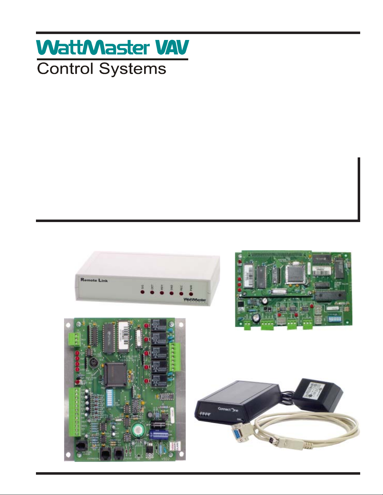
www.wattmaster.com
VAV Systems
Technical Guide
Page 2

Table Of Contents
Selecting The Right WattMaster VAV System ................................................................................................ 3
Using the Selection Chart........................................................................................................................................................... 3
Networked Single Loop System ...................................................................................................................... 4
Operators Interface Options ....................................................................................................................................................... 4
Communication Device Options ................................................................................................................................................. 4
Add-on Device Requirements..................................................................................................................................................... 5
Networked Multiple Loop System ................................................................................................................... 6
Operators Interface Options ....................................................................................................................................................... 6
Communication Device Options ................................................................................................................................................. 6
Add-on Device Requirements..................................................................................................................................................... 7
Figure 1: Typical Networked Single Loop System - Connections & Wiring ............................................................................... 8
Figure 2: Typical Networked Single Loop System - Connections & Wiring Using Computer & Remote Link ........................ 9
Figure 3: Typical Networked Single Loop System - Connections & Wiring Using Computer & IP-Link................................ 10
Figure 4: Typical Networked Multiple Loop System - Connections & Wiring ...........................................................................11
Figure 5: Typical Networked Multiple Loop System - Connections & Wiring Using Computer & Remote Link ................... 12
Figure 6: Typical Networked Multiple Loop System - Connections & Wiring Using Computer & IP-Link............................. 13
Notes:............................................................................................................................................................. 14
WattMaster Controls Inc.
8500 NW River Park Drive · Parkville , MO 64152
Toll Free Phone: 866-918-1100
PH: (816) 505-1100 · FAX: (816) 505-1101 · E-mail: mail@wattmaster.com
Visit our web site at www.wattmaster.com
Form: WM-VAV-SYS-TGD-01A Copyright 2004 WattMaster Controls, Inc.
WattMaster Controls, Inc. assumes no responsibility for errors, or omissions.
Page 3
Selecting The Right WattMaster VAV System
Technical Guide
The WattMaster VAV series of controllers and components are connected together with communication wiring to form complete systems
solutions. W attMaster VA V controllers can be configured into two main
system types, which are the Networked Single Loop or the Networked
Multiple Loop system. The right system for you depends on the number
and types of controllers being used. Each of these main system types
have a series of options available that relate to what kind of operators
interface(s) you wish to use to program and monitor your WattMaster
VAV system. Several other options are available depending on the system type and operators interface you have selected. By selecting the
right system and options you can build a complete HVAC controls system that will meet your job requirements.
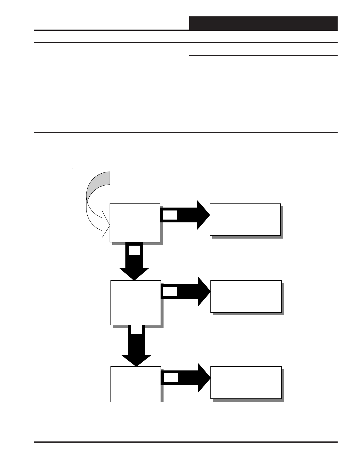
Which WattMaster VAV System
Should I Select?
Do You Have A Single
HVAC Unit With
VAVBOX Controllers
Total Number of All
Controllers Combined
Cannot Exceed 59
YES
Using the Selection Chart
WattMaster has designed this publication in order to make it easy to
select the right WattMaster VAV system type for your specific application. Start by selecting a main system type from the selection chart below. Proceed to the pages listed on the selection chart for information
and available options for that system type. After deciding what operators interface and other options you want, proceed to the connections &
wiring section pages listed for that system type for detailed installation
information.
Use The Networked
Single Loop System
See Pages 4, 5 & 6
NO
Do You Have Between
1 to 59 HVAC Unit or
Add-On Co n trolle r s
With One Un it That h as
VAVBOX Contr ollers .
Total Number of All
Controllers Combined
Cannot Exceed 59
NO
Do You Have More Than
59 HVAC Unit Or Add-On
Controllers And/Or
Multiple HVAC Units
Using VAVBOX
Controllers
YES
YES
Use The Networked
Single Loop System
See Pages 4, 5 & 6
Use The Networked
Multiple Loop System
See Pages 7, 8 & 9
Systems
3
Page 4

Technical Guide
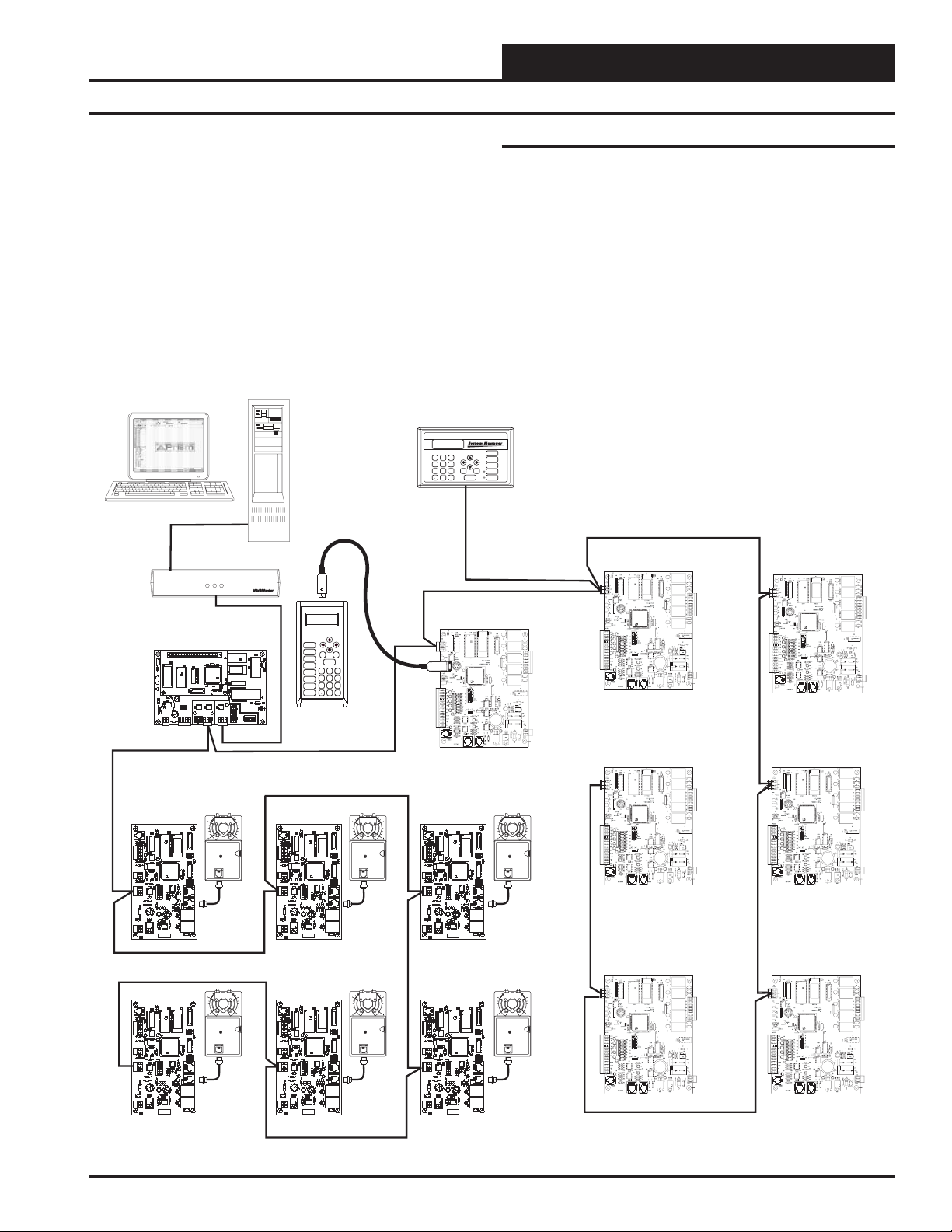
Networked Single Loop System
The Networked Single Loop system is used when you have between 1
to 59 WMVAV controllers, VAVBOX controllers and Add-on Device
controllers total. Only one of the WMVAV controllers on the loop may
also have VAVBOX controllers attached. If your system exceeds any of
these limitations you will need a Networked Multiple Loop System.
When your proposed system has WMVAV and/ or Add-on Device controllers with only 1 WMVAVcontroller that has VAVBOX controllers
and the total number of these controllers and Add-on Devices is 59 or
less, you should use the Networked Single Loop System. If you have
more than 1 WMVAV with VAVBOX controllers or more than 59 total
controllers and Add-on Devices, please see the Networked Multiple Loop
section that follows. To create this system simply connect the controllers together in a daisy chain fashion using WattMaster communications wire or 18 gauge 2 conductor twisted pair with shield wire (Belden
#82760 or equivalent). These are then connected to the system communication devices. All WattMaster VAV systems require that a
CommLink II and a MiniLink Polling Device system communication
device are purchased and wired into the communications loop. The
required CommLink and MiniLink Polling Device are available as a
kit by ordering the OE715-VAV WMVAV System Package. Programming and status monitoring are accomplished by selecting and installing an operators interface. For most controllers, any one of the operators interfaces can be used for system programming and monitoring or
two or all three can be used together if desired. The exception to this is
when any Add-on Devices are used. The Add-on Devices must be programmed with a PC using the WattMaster VAV Prism software, they
cannot be programmed with the System Manager or the Modular Service T ool. See the section titled “Operators Interface Options” that follows for a list and block connection diagrams of the operators interface
options available along with their capabilities and limitations. For detailed wiring and connection diagrams of the Networked Single Loop
systems see pages 10, 11 and 12.
Operators Interface Options
Modular Service Tool
The Modular Service T ool provides complete programming and monitoring capabilities for WMVAV and VAVBOX controllers. Add-on Device controllers cannot be programmed with the Modular Service T ool.
The Modular Service Tool connects to the controller by means of a
modular cable with DIN connectors. It is normally used to program and
service the unit and then is removed by the service person upon completion of these tasks. The Service Tool is not designed for permanent installation. Generally the service person would only connect it when servicing or reprogramming the controller. For this reason if continuous
monitoring of the controllers is required, it is better to select a System
Manager or an on site PC for programming and monitoring. The Service T ool can be used in conjunction with the other operators interfaces
if desired.
System Manager
The System Manager provides programming and monitoring of controllers in a package that is designed for permanent wall mounting in
the space or an equipment room. It is housed in an off white plastic
housing that is suitable for most decors. The System Manager is also
provided with alarm and override LED indicators on its faceplate. Addon Device controllers cannot be programmed with a System Manager.
.
Personal Computer With Prism Software
A computer interface can also be used in conjunction with the other
operators interfaces listed above, or by itself. The PC used can be a
laptop or desktop computer. WattMaster VAV Prism software must be
installed on the PC. WattMaster VAV Prism Software is available free
of charge at our website, www.wattmaster.com. If remote connection
via a phone line is required you must also purchase and install a Remote
Link. For remote computer connection via an intranet or Internet you
would purchase and install the IP-Link instead of the Remote Link.
Both an on-site and remote PC can be used together if desired.
The personal computer to be used with the Orion Prism software must
meet or exceed the following specifications:
• IBM™ Compatible Computer
• Pentium 200 MHz or Faster Microprocessor
• 64 Meg RAM
• Windows 95 / 98 / ME / XP / 2000/ NT
• Super VGA Monitor w/ 1024 x 768 Resolution Minimum
• Available Serial Port for On Site Installations
• Internal or External Modem for Remote Installations
• Network Card for TCP/IP Communications
A PC with Prism installed provides features not available with the other
operators interfaces:
• Trend logs can be exported for easy use into any standard
spreadsheet/database program
• Automatic installation
• Alarm logs are maintained on disk
• E-mailing of alarms
• History logs of user interactions with the system
• On site or remote modem or TCP/IP communications
• User programmable descriptions for every piece of
equipment
• User definable passcode levels for setpoints
• Current status printouts
• User defined custom screens for floor plans, etc.
• Tenant log creation for tenant override Billing
• Automatic retrieval of trend logs
Communication Device Options
All Networked Single Loop system require that you have both a
CommLink and MiniLink PD installed on the system for correct operation. Other optional communication devices are listed in the following
paragraphs along with a description of how they function with the Networked Single Loop control system.
4
Systems
Page 5
Technical Guide
Remote Link
The Remote Link is used with the CommLink to provide for a remote
PC to interface to the system via a phone line. It can also be used with
the CommLink to provide alarm callouts to a pager without requiring
an on site or remote PC.
IP-Link
The IP-Link is used with the CommLink to provide for a remote PC to
interface to the system via a local intranet or the Internet. The IP-Link
will allow up to 5 computer TCP/IP connections to be operating at the
same time.
PERSONAL COMPUTER
CLII
omm ink
MINILINK PD
RV1
F
E
CX3
R
V
U3
CX4
2
U4
X
C
4
R
LED1
LED2
EPROM
RAM
2
X
POWER
C
C8
26
25
C7
R
R
1
V
27
AIN2
AIN1
R
THERM
THERM
4-20mA
4-20mA
U12
0-10V
0-10V
31
R
OFF=0-5V
C
D
1
2
4
N
D
+5V
AIN
AIN
24VA
G
C11
1
D5
TB2
TB
LOCAL LOOP
COMMLINK
RLINK
COMP
LOOP
STATUS
NETWORK LOOP
P1
C4
YS101818P552
X1
PROCESSORPBOARD
C1
C2
CX5
U5
PHILIPS
1
D
U1
1
1
R
U6
CX1
C3
U2
CX6
R2
WDOG
24
R
LD4
PROC.
LOOP
NETWORK
DRIVER
DRIVER
DRIVER
15
14
13
X
X
X
C
C
C
14
13
15
U
U
U
LD6
LD5
NETWORK
LOCALLOOP
LOOP
LD
LD
D
N
P4
G
R
SH
T
R
T
SH
3
4
TB
TB
CONTROLS
UP
Mode
Selection
NEXT
PREV
U1
CX7
U7
1
CX
X6
C
U6
U10
YS101900PMINILINK
POLLING
DEVICE
REV.1
RN2
U11
C9
RN3
X2
3
R28
P
R29
R30
4
1
2
8
32
16
P5
D
D
A
OFF
SW1
STATUS
SETPOINTS
DOWN
CLEAR
1
C
R3
X1
3
C
C10
ESC
SCHEDULES
ENTER
OVERRIDES
13
2
ALARMS
CONFIGURATION
BALANCE-TEST
708
DEC
ON
MODULAR
SERVICE
TOOL
654
9
MINUS
-
SYSTEM MANAGER
UP
13
2
PREV
654
ESC
DOWN
708
9
DEC
MINUS
ENTER
-
WMVAV CONTROLLER
(Variable Volume)
Add-on Device Requirements
If you wish to use any of the Add-on Device controllers on your system
you must use a PC with the Prism software installed for programming
and monitoring of the controllers. These devices cannot be programmed
or monitored from the System Manager or Service Tool.
The Add-on Controllers that require a PC for programming and monitoring are:
• GPC and GPC-17
• Lighting Controller
• Optimal Start Scheduler
STATUS
SETPOINTS
NEXT
SCHEDULES
CLEAR
OVERRIDES
ALARMS
WMVAV CONTROLLER
(Constant Volume)
(1MEG)
(1MEG)
WMVAV CONTROLLER
(Constant Volume)
WMVAV CONTROLLER
(Constant Volume)
(1MEG)
WMVAV CONTROLLER
(Constant Volume)
VAVBOX
CONTROLLER - TYP
AIRFLOW
CX4
CX3
CX1
CX8
RN1
U3
U4
U8
PJ3
P.U.
D5
R27
D6
P.U.
R32
T'STAT
R28
R33
D7
COMM
485
DR
R26
YS101562REV.3
D4
R35
V3
24VAC
GND
C16
AIRFLOW
PJ3
P.U.
D5
R27
D6
P.U.
R32
T'STAT
R28
R33
D7
COMM
485
DR
R26
YS101562REV.3
D4
R35
V3
24VAC
GND
C16
U1
R34
R18
CX9
U9
C13
C9
C14
R22
VREF
ADJ
P.U.
C10
R23
R24
U11
R19
R20
C11
C15
EWDOG
R25
ADDRESS
ADD
CX10
OFF
U10
SW1
V
POWER
SCAN
R21
L1
VR1
OI
7824
R16
R17
CX8
RN1
U8
R34
R18
CX9
U9
C13
C9
C14
R22
VREF
ADJ
P.U.
C10
R23
R24
U11
R19
R20
C11
C15
EWDOG
R25
ADDRESS
ADD
CX10
OFF
U10
SW1
V
POWER
SCAN
R21
L1
VR1
OI
7824
R16
R17
0
PAL
R1
R2
Q1
R3
EPROM
C8
U5
CX2
X1
C1
U2
C2
R4
CX5
R5
R6
R8
R7
PJ1
U6
1
EXPANSION
2
4
CX6
C3
8
16
32
C4
TOKEN
C5
PJ2
R100
NET
ACTUATOR
R14
R13
REC
V1
R9
K1
R12
R11
C6
Q2
D1
D3
K2
C7
R15
Q3
U7
D2
V2
CX4
CX3
CX1
U3
U4
U1
0
PAL
R1
R2
Q1
R3
EPROM
C8
U5
CX2
X1
C1
U2
C2
R4
CX5
R5
R6
R8
R7
PJ1
U6
1
EXPANSION
2
4
CX6
C3
8
16
32
C4
TOKEN
C5
PJ2
R100
NET
ACTUATOR
R14
R13
REC
V1
R9
K1
R12
R11
C6
Q2
D1
D3
K2
C7
R15
Q3
U7
D2
V2
AIRFLOW
CX4
CX3
CX1
CX8
RN1
U3
U4
U8
1
1
PJ3
P.U.
D5
R27
D6
P.U.
R32
T'STAT
R28
R33
D7
COMM
485
DR
R26
YS101562REV.3
D4
R35
V3
24VAC
GND
C16
AIRFLOW
PJ3
P.U.
D5
R27
D6
P.U.
R32
T'STAT
R28
R33
D7
COMM
485
DR
R26
YS101562REV.3
D4
R35
V3
24VAC
GND
C16
U1
R34
R18
CX9
U9
C13
C9
C14
R22
VREF
ADJ
P.U.
C10
R23
R24
U11
R19
R20
C11
C15
EWDOG
R25
ADDRESS
ADD
CX10
OFF
U10
SW1
V
POWER
SCAN
R21
L1
VR1
OI
7824
R16
R17
CX8
RN1
U8
R34
R18
CX9
U9
C13
C9
C14
R22
VREF
ADJ
P.U.
C10
R23
R24
U11
R19
R20
C11
C15
EWDOG
R25
ADDRESS
ADD
CX10
OFF
U10
SW1
V
POWER
SCAN
R21
L1
VR1
OI
7824
R16
R17
0
PAL
R1
R2
Q1
R3
EPROM
C8
U5
CX2
X1
C1
U2
C2
R4
CX5
R5
R6
R8
R7
PJ1
U6
1
EXPANSION
2
4
CX6
C3
8
16
32
C4
TOKEN
C5
PJ2
R100
NET
ACTUATOR
R14
R13
REC
V1
R9
K1
R12
R11
C6
Q2
D1
D3
K2
C7
R15
Q3
U7
D2
V2
CX4
CX3
CX1
U3
U4
U1
0
PAL
R1
R2
Q1
R3
EPROM
C8
U5
CX2
X1
C1
U2
C2
R4
CX5
R5
R6
R8
R7
PJ1
U6
1
EXPANSION
2
4
CX6
C3
8
16
32
C4
TOKEN
C5
PJ2
R100
NET
ACTUATOR
R14
R13
REC
V1
R9
K1
R12
R11
C6
Q2
D1
D3
K2
C7
R15
Q3
U7
D2
V2
AIRFLOW
CX4
CX3
CX1
CX8
RN1
U3
U4
U8
1
1
PJ3
P.U.
D5
R27
D6
P.U.
R32
T'STAT
R28
R33
D7
COMM
485
DR
V
R26
YS101562REV.3
D4
R35
V3
OI
24VAC
GND
C16
AIRFLOW
RN1
PJ3
P.U.
D5
R27
C13
C14
D6
P.U.
ADJ
R32
T'STAT
R28
R33
R25
D7
COMM
485
DR
V
R26
YS101562REV.3
D4
R35
V3
OI
24VAC
GND
C16
U1
R34
R18
CX9
U9
R1
C13
C9
R2
R3
EPROM
C8
U5
C14
CX2
R22
VREF
ADJ
P.U.
C10
X1
R23
C1
R24
C2
U11
R19
R20
C11
C15
R4
CX5
EWDOG
R5
R25
ADDRESS
R6
R8
ADD
R7
CX10
PJ1
OFF
U6
1
2
4
CX6
U10
C3
SW1
8
16
32
POWER
C4
TOKEN
C5
PJ2
R100
NET
R14
R13
SCAN
REC
V1
R21
R9
R12
R11
C6
Q2
L1
D1
D3
VR1
C7
R15
7824
Q3
U7
R16
R17
D2
V2
CX4
CX3
CX1
CX8
U3
U4
U8
R34
R18
CX9
U9
R1
C9
R2
R3
EPROM
C8
U5
CX2
R22
VREF
P.U.
C10
X1
R23
C1
R24
C2
U11
R19
R20
C11
C15
R4
CX5
EWDOG
R5
ADDRESS
R6
R8
ADD
R7
CX10
PJ1
OFF
U6
1
2
4
CX6
U10
C3
SW1
8
16
32
POWER
C4
TOKEN
C5
PJ2
R100
NET
R14
R13
SCAN
REC
V1
R21
R9
R12
R11
C6
Q2
L1
D1
D3
VR1
C7
R15
7824
Q3
U7
R16
R17
D2
V2
1
0
PAL
Q1
U2
EXPANSION
ACTUATOR
K1
K2
U1
1
0
PAL
Q1
U2
EXPANSION
ACTUATOR
K1
K2
Typical Networked Single Loop System With All Operators Interface Options
Systems
(1MEG)
ADD-ON DEVICE
(1MEG)
(1MEG)
ADD-ON DEVICE
(1MEG)
5
Page 6

Technical Guide
Networked Multiple Loop System
The Networked Multiple Loop system is used when you have more
than 59 WMVAV controllers and/or Add-on Device controllers or are
using multiple WMVAV controllers that are connected to VAVBOX
controllers. These groups of controllers are broken up into multiple
“Local Loops” which connect to each other via the “Network Loop”.
Each individual MiniLink PD handles its specific local loop’s communications requirements. The CommLink communications interface
handles all the communications between the individual MiniLink PDs
to form the network loop. Up to 60 local loops can connected together
with this configuration. This provides the capability for over 3500 controllers to be networked together.
If you have more than 59 WMVAV and or Add-on Device controllers or
multiple WMVAV controllers that have VAVBOX controllers you must
split them into separate local loops with no more than 59 controllers
total on each local loop and only 1 WMVAV with VAVBOX controllers
on each loop. Each loop must have its own MiniLink PD. T o create this
system simply connect the controllers together on each local loop in a
daisy chain fashion using W attMaster communications wire or 18 gauge
2 conductor twisted pair with shield wire (Belden #82760 or equivalent). These loops are then connected to the system communication
devices. The Networked Multiple Loop systems require that 1
CommLink and 1 MiniLink Polling Device per local loop are purchased and wired into the communications loop. The required
CommLink and 1 MiniLink Polling Device are available as a kit by
ordering the OE715-VAV WMVAV System Package. The other
MiniLink PDs for each local loop are ordered individually. The
MiniLink PDs on the system are connected together in daisy chain fashion between their network loop terminals by using W attMaster communications wire or 18 gauge 2 conductor twisted pair with shield wire
(Belden #82760 or equivalent). The first MiniLink PD on the network
loop also connects to the CommLink using 18 gauge 2 conductor twisted
pair with shield wire. Programming and status monitoring are accomplished by selecting and installing an operators interface. For most
controllers, any one of the operators interfaces can be used for system
programming and monitoring or two or all three can be used together if
desired. The exception to this is when any Add-on Devices are used.
The Add-on Devices must be programmed with a PC using the WattMaster VAV Prism software, they cannot be programmed with the System Manager or the Modular Service Tool. See the section titled “Operators Interface Options” below for a list and block connection diagrams of the operators interface options available along with their capabilities and limitations. For actual detailed wiring and connection diagrams of the Networked Multiple Loop systems see pages 13, 14 and
15.
Operators Interface Options
Service Tool
The Service Tool provides complete programming and monitoring capabilities for the controllers. It can be connected to any controller on
the loop. The Service Tool connects to the controller by means of a
modular cable with DIN connectors. It is normally used to program and
service the unit and then is removed by the service person upon completion of these tasks. The Service Tool is not designed for permanent installation. Generally the service person would only connect it when servicing or reprogramming the controller. For this reason if continuous
monitoring of the controllers is required, it is better to select a System
Manager or an on site PC for programming and monitoring. The Service T ool can be used in conjunction with the other operators interfaces
if desired.
System Manager
The System Manager provides programming and monitoring of the controllers in a package that is designed for permanent wall mounting in
the space or an equipment room. It is housed in an off white plastic
housing that is suitable for most decors. The System Manager is also
provided with alarm and override LED indicators on its faceplate.
.
Personal Computer With Prism Software
A computer interface can also be used in conjunction with the other
operators interfaces listed above, or by itself. The PC used can be a
laptop or desktop computer. WattMaster VAV Prism software must be
installed on the PC. WattMaster VAV Prism Software is available free
of charge at our website, www.wattmaster.com. If remote connection
via a phone line is required you must also purchase and install a Remote
Link. For remote computer connection via an intranet or Internet you
would purchase and install the IP-Link instead of the Remote Link.
Both an on-site and remote PC can be used together if desired.
The personal computer to be used with the Orion Prism software must
meet or exceed the following specifications:
• IBM™ Compatible Computer
• Pentium 200 MHz or Faster Microprocessor
• 64 Meg RAM
• Windows 95 / 98 / ME / XP / 2000/ NT
• Super VGA Monitor w/ 1024 x 768 Resolution Minimum
• Available Serial Port for On Site Installations
• Internal or External Modem for Remote Installations
• Network Card for TCP/IP Communications
A PC with Prism installed provides features not available with the other
operators interfaces:
• Trend logs can be exported for easy use into any standard
spreadsheet/database program
• Automatic installation
• Alarm logs are maintained on disk
• E-mailing of alarms
• History logs of user interactions with the system
• On site or remote modem or TCP/IP communications
• User programmable descriptions for every piece of
equipment
• User definable passcode levels for setpoints
• Current status printouts
• User defined custom screens for floor plans, etc.
• Tenant log creation for tenant override Billing
• Automatic retrieval of trend logs
Communication Device Options
All Networked Multiple Loop systems require that you have
1CommLink per system and 1MiniLink PD for each local loop installed
on the system for correct operation. Other optional communication de-
6
Systems
Page 7

Technical Guide
vices are listed in the following paragraphs along with a description of
how they function with the Networked Multiple Loop control system.
Remote Link
The Remote Link is used with the CommLink to provide for a remote
PC to interface to the system via a phone line. It can also be used with
the CommLink to provide alarm callouts to a pager without requiring
an on site or remote PC.
IP-Link
The IP-Link is used with the CommLink to provide for a remote PC to
interface to the system via a local intranet or the Internet. The IP-Link
will allow up to 5 computer TCP/IP connections to be operating at the
same time.
PERSONAL COMPUTER
COMMLINK
CLII
omm ink
MP
OP
RLINK
CO
LO
STATUS
CONTROLS
LED2
POWER
LOCAL LOOP
RV1
EF
VR
X2
C
4
R
LED1
1
V
31
R
4
D
TB1
CX3
U3
EPROM
C7
R26
R25
U12
C
D
N
G
24VA
C11
D5
MINILINK PD
CX4
CX5
U4
U5
R1
U2
RAM
X2
C
C8
PROC.
DRIVER
27
15
AIN1
AIN2
R
CX
THERM
THERM
4-20mA
4-20mA
0-10V
0-10V
LD6
OFF=0-5V
LOCALLOOP
1
2
ND
IN
IN
P4
+5V
G
A
A
TB2
NETWORK LOOP
U1
P1
C4
YS101818P552
X1
PROCESSORPBOARD
C1
C2
U6
PHILIPS
U10
D1
U1
1
U6
CX1
C3
CX6
R2
WDOG
24
R
LD4
LOOP
NETWORK
DRIVER
DRIVER
14
X13
CX
C
3
P
14
15
13
U
U
U
LD5
NETWORK
LOOP
LD
LD
H
H
R
R
S
T
T
S
P5
3
DD
4
A
TB
TB
CX7
U7
1
X
C
1
C
3
R
1
X
X6
C
YS101900PMINILINK
POLLING
DEVICE
REV.1
RN2
U11
C10
C9
RN3
X2
R28
R29
R30
4
1
2
8
32
16
OFF
SW1
UP
Mode
Selection
NEXT
PREV
STATUS
SETPOINTS
DOWN
CLEAR
ESC
SCHEDULES
ENTER
OVERRIDES
13
2
3
ALARMS
C
CONFIGURATION
BALANCE-TEST
708
DEC
ON
MODULAR
SERVICE
TOOL
654
9
MINUS
-
Add-on Device Requirements
If you wish to use any of the Add-on Device controllers on your system
you must use a PC with the Prism software installed for programming
and monitoring of the controllers. These devices cannot be programmed
or monitored from the System Manager or Service Tool.
The Add-on Controllers that require a PC for programming and monitoring are:
• GPC and GPC-17
• Lighting Controller
• Optimal Start Scheduler
SYSTEM MANAGER
STATUS
UP
13
2
SETPOINTS
NEXT
PREV
654
SCHEDULES
CLEAR
ESC
DOWN
OVERRIDES
708
9
DEC
MINUS
ENTER
ALARMS
-
WMVAVCONTROLLER
(Variable Volume)
(1MEG)
WMVAVCONTROLLER
(Constant Volume)
(1MEG)
WMVAVCONTROLLER
(Constant Volume)
WMVAVCONTROLLER
(Constant Volume)
(1MEG)
WMVAVCONTROLLER
(Constant Volume)
Local Loop #1
Local Loop #2
VAVBOX
CONTROLLER - TYP
AIRFLOW
CX4
CX3
CX8
RN1
U3
U4
U8
PJ3
R34
R18
P.U.
D5
R27
CX9
U9
R1
C13
C9
R2
R3
EPROM
C8
U5
C14
R22
D6
P.U.
VREF
ADJ
P.U.
C10
X1
R32
R23
C1
T'STAT
R28
R24
C2
U11
R19
R20
C11
C15
R4
CX5
R33
EWDOG
R5
R25
D7
ADDRESS
R6
R8
ADD
R7
COMM
CX10
PJ1
OFF
U6
1
2
485
DR
4
CX6
U10
C3
SW1
V
8
16
32
POWER
C4
TOKEN
C5
PJ2
R100
NET
R26
R14
R13
SCAN
REC
V1
YS101562REV.3
D4
R21
R9
R35
R12
R11
C6
Q2
L1
V3
D1
D3
VR1
OI
C7
R15
24VAC
7824
Q3
U7
R16
R17
D2
GND
V2
C16
RV1
EF
CX3
VR
U3
U4
X2
C
4
R
LED1
LED2
EPROM
POWER
C7
R26
R25
V1
27
R
THERM
4-20mA
U12
0-10V
31
R
C
D
N
D4
G
24VA
C11
D5
TB2
TB1
LOCAL LOOP
VAVBOX
CONTROLLER - TYP
AIRFLOW
CX4
CX8
RN1
U3
U4
U8
PJ3
R34
R18
P.U.
D5
R27
CX9
U9
C13
C9
EPROM
C8
U5
C14
R22
D6
P.U.
VREF
ADJ
P.U.
C10
R32
R23
T'STAT
R28
R24
U11
R19
R20
C11
C15
R33
EWDOG
R25
D7
ADDRESS
ADD
COMM
CX10
OFF
U6
1
2
485
DR
4
CX6
U10
SW1
V
8
16
32
POWER
TOKEN
C5
R100
NET
R26
R14
R13
SCAN
REC
YS101562REV.3
D4
R21
R35
R12
R11
C6
Q2
L1
V3
D3
VR1
OI
C7
R15
24VAC
7824
Q3
U7
R16
R17
GND
C16
CX1
U1
0
PAL
Q1
CX2
U2
EXPANSION
ACTUATOR
K1
K2
CX1
U1
0
PAL
Q1
CX2
U2
EXPANSION
ACTUATOR
K1
K2
MINILINK PD
YS101818P552
CX4
PROCESSORPBOARD
C1
CX5
U5
1
1
R
C3
U2
RAM
X2
C
C8
PROC.
DRIVER
15
AIN1
AIN2
X13
CX
C
THERM
15
4-20mA
U
0-10V
LD6
OFF=0-5V
LOCALLOOP
1
2
D
N
P4
+5V
G
T
AIN
AIN
CX3
CX1
U1
PAL
R1
R2
Q1
R3
CX2
X1
C1
U2
C2
R4
CX5
R5
R6
R8
R7
PJ1
EXPANSION
C3
C4
PJ2
ACTUATOR
V1
R9
K1
D1
K2
D2
V2
1
1
NETWORK LOOP
U1
CX7
U7
1
P1
CX
C4
X1
C2
6
X
C
U6
PHILIPS
U10
YS101900PMINILINK
1
D
POLLING
U1
DEVICE
REV.1
U6
CX1
CX6
RN2
U11
R2
WDOG
4
R2
C9
RN3
LD4
LOOP
NETWORK
DRIVER
DRIVER
14
X2
CX
3
4
R28
P
13
U1
U
R29
R30
LD5
NETWORK
D
LOOP
L
LD
4
1
2
8
32
16
H
R
R
SH
T
S
P5
3
DD
4
A
B
OFF
TB
T
SW1
1
0
(1MEG)
AIRFLOW
CX4
CX3
CX1
CX8
RN1
U3
U4
U8
U1
PJ3
R34
R18
0
PAL
P.U.
D5
R27
CX9
U9
R1
C13
C9
R2
Q1
R3
EPROM
C8
U5
C14
CX2
R22
D6
P.U.
VREF
ADJ
P.U.
C10
X1
R32
R23
C1
U2
T'STAT
R28
R24
C2
U11
R19
R20
C11
C15
R4
CX5
R33
EWDOG
R5
R25
D7
ADDRESS
R6
R8
ADD
R7
COMM
CX10
PJ1
OFF
U6
1
EXPANSION
2
485
DR
4
CX6
U10
C3
SW1
V
8
16
32
POWER
C4
TOKEN
C5
PJ2
R100
NET
R26
ACTUATOR
R14
R13
SCAN
REC
V1
YS101562REV.3
D4
R21
R9
R35
K1
R12
R11
C6
Q2
L1
V3
D1
D3
VR1
OI
K2
C7
R15
24VAC
7824
Q3
U7
R16
R17
D2
GND
V2
C16
AIRFLOW
CX4
CX3
CX1
CX8
RN1
U3
U4
U8
U1
PJ3
R34
1
R18
P.U.
D5
R27
CX9
U9
C13
C9
EPROM
C8
U5
C14
R22
D6
P.U.
VREF
ADJ
P.U.
C10
R32
R23
T'STAT
R28
R24
U11
R19
R20
C11
C15
R33
EWDOG
R25
D7
ADDRESS
ADD
COMM
CX10
OFF
U6
1
2
485
DR
4
CX6
U10
SW1
V
8
16
32
POWER
TOKEN
C5
R100
NET
R26
R14
R13
SCAN
REC
YS101562REV.3
D4
R21
R35
R12
R11
C6
L1
V3
D3
VR1
OI
C7
R15
24VAC
7824
U7
R16
R17
GND
C16
1
0
PAL
R1
R2
Q1
R3
CX2
X1
C1
U2
C2
R4
CX5
R5
R6
R8
R7
PJ1
EXPANSION
C3
C4
PJ2
ACTUATOR
V1
R9
K1
Q2
D1
K2
Q3
D2
V2
ADD-ON DEVICE
AIRFLOW
CX4
CX3
CX1
CX8
RN1
U3
U4
U8
U1
PJ3
R34
R18
0
PAL
P.U.
D5
R27
CX9
U9
R1
C13
C9
R2
Q1
R3
EPROM
C8
U5
C14
CX2
R22
D6
P.U.
VREF
ADJ
P.U.
C10
X1
R32
R23
C1
U2
T'STAT
R28
R24
C2
U11
R19
R20
C11
C15
R4
CX5
R33
EWDOG
R5
R25
D7
ADDRESS
R6
R8
ADD
R7
COMM
CX10
PJ1
OFF
U6
1
EXPANSION
2
485
DR
4
CX6
U10
C3
SW1
V
8
16
32
POWER
C4
TOKEN
C5
PJ2
R100
NET
R26
ACTUATOR
R14
R13
SCAN
REC
V1
YS101562REV.3
D4
R21
R9
R35
K1
R12
R11
C6
Q2
L1
V3
D1
D3
VR1
OI
K2
C7
R15
24VAC
7824
Q3
U7
R16
R17
D2
GND
V2
C16
1
C
3
R
X1
3
C
C10
AIRFLOW
CX4
CX3
CX1
CX8
RN1
U3
U4
U8
U1
PJ3
R34
R18
0 0
PAL
P.U.
D5
R27
CX9
U9
R1
C13
C9
R2
Q1
R3
EPROM
C8
U5
C14
CX2
R22
D6
P.U.
VREF
ADJ
P.U.
C10
X1
R32
R23
C1
U2
T'STAT
R28
R24
C2
U11
R19
R20
C11
C15
R4
CX5
R33
EWDOG
R5
R25
D7
ADDRESS
R6
R8
ADD
R7
COMM
CX10
PJ1
OFF
U6
1
EXPANSION
2
485
DR
4
CX6
U10
C3
SW1
V
8
16
32
POWER
C4
TOKEN
C5
PJ2
R100
NET
R26
ACTUATOR
R14
R13
SCAN
REC
V1
YS101562REV.3
D4
R21
R9
R35
K1
R12
R11
C6
Q2
L1
V3
D1
D3
VR1
OI
K2
C7
R15
24VAC
7824
Q3
U7
R16
R17
D2
GND
V2
C16
AIRFLOW
CX4
CX3
CX1
CX8
RN1
U3
U4
U8
U1
PJ3
R34
1
R18
P.U.
D5
R27
CX9
U9
C13
C9
C8
U5
C14
R22
D6
P.U.
VREF
ADJ
P.U.
C10
R32
R23
T'STAT
R28
R24
U11
R19
R20
C11
C15
R33
EWDOG
R25
D7
ADDRESS
ADD
COMM
CX10
OFF
U6
1
2
485
DR
4
U10
SW1
V
8
16
32
POWER
TOKEN
C5
NET
R26
R14
R13
SCAN
REC
YS101562REV.3
D4
R21
R35
R12
C6
L1
V3
D3
VR1
OI
C7
R15
24VAC
7824
U7
R16
R17
GND
C16
WMVAVCONTROLLER
(Variable Volume)
1
0
PAL
R1
R2
Q1
R3
EPROM
CX2
X1
C1
U2
C2
R4
CX5
R5
R6
R8
R7
PJ1
EXPANSION
CX6
C3
C4
PJ2
R100
ACTUATOR
V1
R9
K1
R11
Q2
D1
K2
Q3
D2
V2
WMVAVCONTROLLER
(Constant Volume)
(1MEG)
AIRFLOW
CX4
CX3
CX1
CX8
RN1
U3
U4
U8
U1
PJ3
R34
1 1
R18
0 0
PAL
P.U.
D5
R27
CX9
U9
R1
C13
C9
R2
Q1
R3
EPROM
C8
U5
C14
CX2
R22
D6
P.U.
VREF
ADJ
P.U.
C10
X1
R32
R23
C1
U2
T'STAT
R28
R24
C2
U11
R19
R20
C11
C15
R4
CX5
R33
EWDOG
R5
R25
D7
ADDRESS
R6
R8
ADD
R7
COMM
CX10
PJ1
OFF
U6
1
EXPANSION
2
485
DR
4
CX6
U10
C3
SW1
V
8
16
32
POWER
C4
TOKEN
C5
PJ2
R100
NET
R26
ACTUATOR
R14
R13
SCAN
REC
V1
YS101562REV.3
D4
R21
R9
R35
K1
R12
R11
C6
Q2
L1
V3
D1
D3
VR1
OI
K2
C7
R15
24VAC
7824
Q3
U7
R16
R17
D2
GND
V2
C16
AIRFLOW
CX4
CX3
CX1
CX8
RN1
U3
U4
U8
U1
PJ3
R34
1 1
R18
PAL
P.U.
D5
R27
CX9
U9
R1
C13
C9
R2
Q1
R3
EPROM
C8
U5
C14
CX2
R22
D6
P.U.
VREF
ADJ
P.U.
C10
X1
R32
R23
C1
U2
T'STAT
R28
R24
C2
U11
R19
R20
C11
C15
R4
CX5
R33
EWDOG
R5
R25
D7
ADDRESS
R6
R8
ADD
R7
COMM
CX10
PJ1
OFF
U6
1
EXPANSION
2
485
DR
4
CX6
U10
C3
SW1
V
8
16
32
POWER
C4
TOKEN
C5
PJ2
R100
NET
R26
ACTUATOR
R14
R13
SCAN
REC
V1
YS101562REV.3
D4
R21
R9
R35
K1
R12
R11
C6
Q2
L1
V3
D1
D3
VR1
OI
K2
C7
R15
24VAC
7824
Q3
U7
R16
R17
D2
GND
V2
C16
(1MEG)
(1MEG)
AIRFLOW
CX4
CX8
RN1
U4
U8
PJ3
R34
R18
P.U.
D5
R27
CX9
U9
C13
C9
C8
C14
R22
D6
P.U.
VREF
ADJ
P.U.
C10
R32
R23
T'STAT
R28
R24
U11
R19
R20
C11
C15
R33
EWDOG
R25
D7
ADDRESS
ADD
COMM
CX10
OFF
U6
1
2
485
DR
4
U10
SW1
V
8
16
32
POWER
TOKEN
NET
R26
R14
SCAN
REC
YS101562REV.3
D4
R21
R35
L1
V3
D3
VR1
OI
C7
24VAC
7824
U7
R16
R17
GND
C16
ADD-ON DEVICE
WMVAVCONTROLLER
(Constant Volume)
CX3
CX1
U3
U1
PAL
R1
R2
Q1
R3
EPROM
U5
CX2
X1
C1
U2
C2
R4
CX5
R5
R6
R8
R7
PJ1
EXPANSION
CX6
C3
C4
C5
PJ2
R100
ACTUATOR
R13
V1
R9
K1
R12
R11
C6
Q2
D1
K2
R15
Q3
D2
V2
(1MEG)
(1MEG)
(1MEG)
Typical Multiple Loop System With All Operators Interface Options
Systems
7
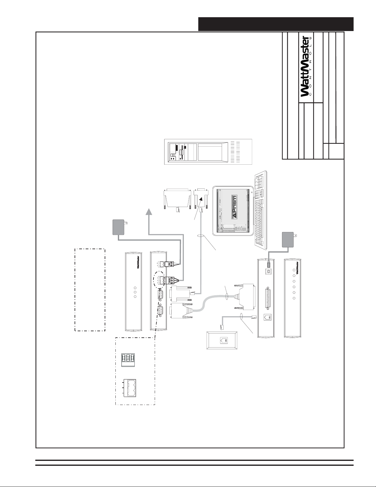
Page 8

Technical Guide
SHLD
T
LOOP
R
G
T
WMVAV Controller
R
485
Typical Terminal Blocks. All
Wiring To Be T To T, SHLD (G)
To SHLD (G)&RToR
Typical Single Loop Networked System
WHITE (T)
Note: A Modular System
Manager, A Modular Service
NEXT
UP
PREV
STATUS
Mode
Selection
(1MEG)
DRAIN WIRE (SHLD)
BLACK (R)
Tool Or A PC With Prism
Software Installed Can Be
Used To Program And
Configure TheWattMaster
P
CommLink
Front View of CommLink
CLEAR
DOWN
ENTER
ESC
SETPOINTS
SCHEDULES
Line Voltage
RED (24 VAC)
VAV System.
110 VA C To
RLINK
COM
LOOP
6
2
5
13
4
ALARMS
OVERRIDES
CONFIGURATION
24 VAC
(6 VA)
GREEN (GND)
BROWN (GND)
Connect To Modular
I/O Connectors
24 VAC
Power Pack
CONTROLS
STATUS
Back View of CommLink
9
-
MINUS
0
8
7
DEC
ON
BALANCE-TEST
Located On Back
Of The System Manager
GND
24V
R
G
T
(DCE)
COMPUTER
(DTE)
REMOTE LINK
TB1
ER
LOOP
Modular Service
24 VAC
(8 VA)
POW
485
Tool
Line Voltage
STATUS
SETPOINTS
UP
2
13
NEXT
PREV
SCHEDULES
6
5
4
Connect To Next
VAVBOX Controller
1 1
0 0
1
0
ALARMS
OVERRIDES
CLEAR
DOWN
ENTER
ESC
9
-
MINUS
0
8
7
DEC
Local Loop
Modular System Manager
MiniLink PD Loop 1
ACTUATOR
EXPANSION
U2
Q1
PAL
VAVBOX
Controller
U1
ACTUATOR
EXPANSION
U2
Q1
PAL
VAVBOX
Controller
U1
ACTUATOR
EXPANSION
U2
Q1
VAVBOX
Controller
PAL
U1
C
1
X
1
R
3
CX7
U7
C
X6
C
X1
U1
C4
P1
C2
X1
YS101818P552
PROCESSORPBOARD
C1
CX5
U5
CX4
U4
CX3
U3
C
X
2
RV1
R
4
V
R
E
F
24 VAC
V2
K2
R17
R16
D2
U7
Q3Q2
R15
7824
C7
D3
D1
K1
VR1
L1
R10
R12C6R11
SCAN
REC
R9
R21
LD2
LD1
V1
R14
R13
NET
PJ2
R100
C4
TOKEN
C5
POWER
LD3
32
16
8
C3
U10
CX6
SW1
4
75176
R8
2
U6
1
PJ1
R7
R6
R5
CX5
R4
C2C1
X1
CX2
R3
R2
R1
16L8
CX1
CX3
V2
V1
PJ2
PJ1
R7
R6
R5
CX5
R4
C2C1
X1
CX2
R3
R2
R1
16L8
CX1
CX3
V2
PJ2
PJ1
R7
R6
R5
R4
C2C1
X1
CX2
R3
R2
R1
16L8
CX1
CX3
C3
YS101900PMINILINK
POLLING
DEVICE
U6
U10
D
1
U1
PHILIPS
1
LED1
LED2
CX10
ADD
ADDRESS
U5
R25
EWDOG
C15
R20
C11
R19
U11
R24
R23
C10
P.U.
VREF
ADJ
2
R22
80C55
C14
C8
EPROM
RAM
C13
C9
U9
CX9
1
RN1
U8
U3
U4
CX8
CX4
R34
R18
K2
R17
D2
R16
U7
Q3Q2
R15
7824
C7
D3
D1
K1
VR1
L1
R12C6R11
R10
SCAN
REC
R9
R21
LD2
LD1
R14
R13
NET
R100
C4
TOKEN
C5
POWER
LD3
32
16
8
U10
C3
CX6
SW1
4
75176
R8
2
U6
1
CX10
ADD
ADDRESS
U5
R25
EWDOG
C15
R20
C11
R19
U11
R24
R23
C10
P.U.
VREF
ADJ
2
R22
80C55
C14
C8
EPROM
RAM
C13
C9
U9
CX9
1
RN1
U8
U3
U4
CX8
CX4
R34
R18
K2
R17
D2
R16
U7
Q3Q2
R15
7824
C7
D3
D1
K1
VR1
L1
R12C6R11
R10
SCAN
REC
R9
R21
LD2
LD1
V1
R14
R13
NET
R100
C4
TOKEN
C5
POWER
LD3
32
16
8
C3
U10
CX6
SW1
4
75176
R8
2
U6
1
CX10
ADD
ADDRESS
U5
R25
EWDOG
CX5
REV.1
U6
CX1
R
1
C15
R20
C11
R19
U11
R24
R23
C10
P.U.
VREF
ADJ
2
R22
80C55
C14
C8
EPROM
RAM
C13
C9
U9
CX9
U8
U3
U4
CX8
CX4
R34
R18
C10
R30X2R29
R28
32
U11
C9
16
8
4
2
RN2
1
RN3
P3
P5
R24
LD4
R
U
14
CX6
LD
SH
WDOG
T
NETWORK
DRIVER
C
X
14
NETWORK
LOOP
R2
U
13
LD5
R
LD
H
S
LOOP
DRIVER
C3
T
C
X
13
U
15
PROC.
DRIVER
U2
LOCALLOOP
C
X
15
LD6
P4
D
N
G
0-10V
THERM
4-20mA
C
X
2
2
IN
A
AIN2
1
AIN
RAM
OFF=0-5V
C8
+5V
AIN1
0-10V
THERM
4-20mA
R
27
C7
EPROM
D
N
G
U12
C
24VA
R
25
R
26
D
4
R
31
V1
POWER
24 VAC
(6 VA)
(6VA Min.)
GND
24VAC
V3
562REV 3
R35
YS101
D4
R26
R
SHLD
COMM
T
D7
GND
TMP
R28
T'STAT
R32
D5
GND
AUX2
AUX1
+VS
R27
AUX
D5
FLOW
GND
24VAC
V3
562REV 3
R35
YS101
D4
R26
R
SHLD
COMM
T
D7
GND
TMP
R28
T'STAT
R32
D5
GND
AUX2
AUX1
+VS
R27
AUX
D5
FLOW
GND
24VAC
V3
562REV 3
R35
YS101
D4
R26
R
SHLD
COMM
T
D7
GND
TMP
R28
T'STAT
R32
D5
GND
AUX2
AUX1
+VS
R27
AUX
D5
1
RN1
FLOW
OFF
SW1
AD
D
4
TB
3
TB
TB
2
C11
D5
TB
1
Line Voltage
24 VAC
(6VA Min.)
Line Voltage
24 VAC
(6VA Min.)
Line Voltage
Local
Network
JOB NAME
Local
B. Crews
DRAWN BY:
DESCRIPTION:
05/12/04
FILENAME
DATE:
VAV-Network-SingleLoop1B.CDR
PAGE
Network System - Single Loop
1of3
Wiring & Connection Diagram
omm ink
CLII
SERIAL#
Note: See Page 2 Of
This Drawing For
Optional Computer
And Remote Link
Connection Diagram.
Figure 1: T ypical Networked Single Loop System - Connections & Wiring
8
Systems
Page 9
Technical Guide
JOB NAME
FILENAME
B. Crews
DRAWN BY:
DESCRIPTION:
Wiring & Connection Diagram
Network System - Single Loop
03/24/04
DATE:
VAV-Network-SingleLoop1B.CDR
PAGE
2of3
Optional Computer Connection Diagram
Using Remote Link For Remote Connection
Note: If Direct Computer Connection
Is Required, Connect To PC As Shown.
Remote Link Is Only Required If
Alarm Callout Or Remote Computer
Connection Is Required.
110 VA C To
RLINK
COM
P
LOOP
CommLink
Front View of CommLink
omm ink
CLII
SHLD
T
R
LOOP
485
R
G
T
24 VAC
CONTROLS
STATUS
Typical Terminal Blocks. All
Power Pack
Connect To MiniLink PD Network Terminals
See Page 1 Of This Drawing
ER
W
GND
24V
OP
R
G
T
(DCE)
COMPUTER
(DTE)
Back View of CommLink
REMOTE LINK
SERIAL#
Wiring To Be T To T, SHLD (G)
To SHLD (G)&RToR
25 Pin
Female
9 Pin
(If Reqd)
Connector
Female
Connector
(By Others)
Personal Computer
Serial Port
PO
485 LO
Connect To Computer
9 Pin
Female
Connector
Assembly
8 Conductor
Modular Cable
Molded
25 Pin
Male End
POWER
500mA
9VDC @
Cable Assembly
SERIALDATA
LINE
TELCO
Back View of Remote Link
9 Pin
End
Female
Outlet
(By Others)
TELCO
SERIAL#
LINE
Cable
Assembly
Telephone
emote ink
RL
9 VDC
110 VA C To
Power Pack
PWR
CONTROLS
REC
SND
RDY
DET
SIG
(Optional)
Remote Link
Front View of Remote Link
Dedicated Telephone
Figure 2: Typical Networked Single Loop System - Connections & Wiring Using Computer & Remote Link
Systems
9
Page 10

Technical Guide
JOB NAME
B. Crews
DRAWN BY:
DESCRIPTION:
03/24/04
FILENAME
DATE:
VAV-Network-SingleLoop1B.CDR
PAGE
Network System - Single Loop
3of3
Wiring & Connection Diagram
Note: If Direct Computer Connection
Using IP-Link For Remote Connection
Optional Computer Connection Diagram
Is Required, Connect To PC As Shown. IP-Link Is
Only Required If E-mail Alarm Notification Or
Remote Computer Connection Is Required.
Connect To MiniLink PD Network Terminals
See Page 1 Of This Drawing
Note:
1.Set CommLink Internal Switch To”Multi”
2. Replace CommLink EPROM With IP-Link
EPROM Supplied With IP-Link Kit
110 VA C To
RLINK
COM
P
LOOP
CommLink
Front View of CommLink
omm ink
CLII
SHLD
T
R
LOOP
485
R
G
T
24 VAC
CONTROLS
STATUS
Typical Terminal Blocks. All
Power Pack
PO
ER
W
GND
24V
LOOP
485
R
G
T
(DCE)
COMPUTER
(DTE)
Back View of CommLink
REMOTE LINK
SERIAL#
Wiring To Be T To T, SHLD (G)
To SHLD (G)&RToR
25 Pin
Female
9 Pin
(If Reqd)
Connector
Serial Port
Connect To Computer
9 Pin
Female
End
Female
Cable Assembly
Connect Ethernet RJ45
9 Pin
Female
Connector
8 Conductor
Connector
(By Others)
On Ethernet Router
To 10 BaseT Connection
Assembly
Modular Cable
Or Modem
(By Others)
Molded
Supplied With
Cable Assembly
IP-Link Kit
9 Pin Male End
RJ45 Cable
Connect Ethernet
Port On IP-Link
Connect To Serial
9VDC
Serial
10BaseT
Assembly
On IP-Link
To 10BaseT Port
Mode
(By Others)
Personal Computer
ne
onnect
C
Back View of IP-Link
9 VDC
110 VA C To
Power Pack
PWR
R
E
S
V
C
R
LNK
T
C
A
IP-Link
(Optional)
Front View of IP- Link
Figure 3: T ypical Networked Single Loop System - Connections & Wiring Using Computer & IP-Link
10
Systems
Page 11

Technical Guide
SHLD
T
LOOP
R
G
T
R
485
Typical Terminal Blocks. All
Wiring To Be T To T, SHLD (G)
To SHLD (G)&RToR
Typical Multiple Loop Networked System
WMVAV Controller
WHITE (T)
Note: A Modular System Manager,
A Modular Service Tool Or A PC
With Prism Software Installed Can
NEXT
CLEAR
UP
DOWN
ENTER
ESC
PREV
STATUS
Mode
SETPOINTS
OVERRIDES
SCHEDULES
Selection
(1MEG)
Line Voltage
DRAIN WIRE (SHLD)
RED (24 VAC)
BLACK (R)
Be Used To Program And
Configure The WattMaster VAV
System.
110 VA C To
RLINK
COM
P
LOOP
CommLink
Front View of CommLink
6
2
5
13
4
ALARMS
CONFIGURATION
24 VAC
(6 VA)
GREEN (GND)
BROWN (GND)
Connect To Modular
I/O Connectors
24 VAC
Power Pack
CONTROLS
STATUS
Back View of CommLink
9
-
MINUS
0
8
7
DEC
ON
BALANCE-TEST
Located On Back
Of The System Manager
GND
24V
R
G
T
(DCE)
COMPUTER
(DTE)
REMOTE LINK
TB1
ER
LOOP
Modular Service
24 VAC
(8 VA)
POW
485
Tool
Line Voltage
STATUS
SETPOINTS
UP
2
13
NEXT
PREV
Connect To
SCHEDULES
6
5
4
Next VAVBOX
1
0
1
0
1
0
ALARMS
OVERRIDES
CLEAR
DOWN
ENTER
ESC
9
MINUS
0
8
7
DEC
Controller On
-
Loop 1
Modular System Manager
U1
MiniLink PD Loop 1
VAVBOX
VAVBOX
VAVBOX
CX7
U7
CX
1
P1
RV1
V2
K2
D2
Q3Q2
D1
K1
R10
R9
V1
ACTUATOR
PJ2
C4
C3
CX6
R8
EXPANSION
PJ1
R7
R6
R5
CX5
R4
C2C1
U2
X1
Q1
CX2
R3
EPROM
R2
R1
16L8
PAL
U1
U3
CX1
CX3
Controller
V2
K2
D2
D1
K1
R10
R9
V1
ACTUATOR
PJ2
C4
C3
R8
EXPANSION
PJ1
R7
R6
R5
CX5
R4
C2C1
U2
X1
Q1
CX2
R3
R2
R1
16L8
PAL
Controller
U1
U3
CX1
CX3
V2
K2
D2
D1
K1
R10
R9
V1
ACTUATOR
PJ2
C4
C3
R8
EXPANSION
PJ1
R7
R6
R5
CX5
R4
C2C1
U2
X1
Q1
CX2
R3
R2
R1
16L8
Controller
PAL
U1
U3
CX1
CX3
C
3
C1
X1
R3
YS101900PMINILINK
POLLING
DEVICE
REV.1
CX
6
RN2
U6
U10
D1
C4
U6
CX6
U1
C2
PHILIPS
X1
CX1
C3
YS101818P552
PROCESSORPBOARD
C1
1
R
1
U2
CX5
U5
CX4
U4
CX3
U3
C
X
2
R
4
V
R
E
F
LED1
LED2
24 VAC
24 VAC
(6VA Min.)
GND
R17
R16
U7
R15
R12C6R11
R13
R100
C5
24VAC
7824
C7
D3
VR1
V3
L1
562REV 3
SCAN
REC
R35
YS101
R21
LD2
LD1
D4
R14
R26
NET
TOKEN
POWER
LD3
32
R
16
SHLD
8
U10
SW1
4
75176
COMM
2
U6
U5
2
80C55
CX4
T
1
CX10
ADD
ADDRESS
D7
R25
EWDOG
C15
GND
R20
C11
R19
TMP
U11
R24
R28
T'STAT
R23
R32
C10
P.U.
VREF
ADJ
D5
R22
C14
C8
RAM
GND
C13
C9
U9
AUX2
CX9
AUX1
+VS
R27
AUX
D5
1
RN1
U8
U4
CX8
FLOW
R34
R18
Line Voltage
JOB NAME
B. Crews
DRAWN BY:
DESCRIPTION:
Network System - Multiple Loop
Wiring & Connection Diagram
05/12/04
24 VAC
Q3Q2
R15
D3
R12C6R11
R13
R100
C5
CX6
U6
2
80C55
EPROM
CX4
Q3Q2
R15
R12C6R11
R13
R100
C5
CX6
EPROM
CX4
24VAC
7824
C7
VR1
V3
L1
562REV 3
SCAN
REC
R35
YS101
R21
LD2
LD1
D4
R14
R26
NET
TOKEN
POWER
LD3
32
R
16
SHLD
8
U10
SW1
4
75176
COMM
2
T
1
CX10
ADD
ADDRESS
D7
U5
R25
EWDOG
C15
GND
R20
C11
R19
TMP
U11
R24
R28
T'STAT
R23
R32
C10
P.U.
VREF
ADJ
D5
R22
C14
C8
RAM
GND
C13
C9
U9
AUX2
CX9
AUX1
+VS
R27
AUX
D5
1
RN1
U8
U4
CX8
FLOW
R34
R18
GND
R17
R16
U7
24VAC
7824
C7
D3
VR1
V3
L1
562REV 3
SCAN
REC
R35
YS101
R21
LD2
LD1
D4
R14
R26
NET
TOKEN
POWER
LD3
32
R
16
SHLD
8
U10
SW1
4
75176
COMM
2
U6
2
80C55
T
1
CX10
ADD
ADDRESS
D7
U5
R25
EWDOG
C15
GND
R20
C11
R19
TMP
U11
R24
R28
T'STAT
R23
R32
C10
P.U.
VREF
ADJ
D5
R22
C14
C8
RAM
GND
C13
C9
U9
AUX2
CX9
AUX1
+VS
R27
AUX
D5
1
RN1
U8
U4
CX8
FLOW
R34
R18
24 VAC
Line Voltage
(6VA Min.)
Line Voltage
(6VA Min.)
GND
R17
R16
U7
FILENAME
DATE:
VAV-Network-MultLoop1B.CDR
Loop 3
MiniLink Polling Device
Connect To Loop 2
Connect To
1of3
PAGE
VAVBOX Controller
Or WMVAV Controller
Local
Local
C10
R30X2R29
R28
OFF
SW1
32
U11
C9
16
8
4
2
1
RN3
AD
D
P3
P5
R24
LD4
R
U14
LD
H
S
WDOG
T
NETWORK
DRIVER
C
X
14
4
TB
NETWORK
LOOP
R2
3
TB
U
13
LD5
R
LD
SH
LOOP
DRIVER
T
C
X13
U
15
PROC.
DRIVER
LOCALLOOP
C
X
15
LD6
P4
D
N
G
0-10V
THERM
4-20mA
C
X
2
2
IN
A
AIN2
1
AIN
RAM
OFF=0-5V
C8
+5V
AIN1
TB2
0-10V
THERM
4-20mA
R
27
C7
EPROM
D
U12
C
R
25
R
26
R
31
V
1
POWER
Network
C11
D5
N
G
24VA
TB1
D
4
Local
(6 VA)
C
3
C
1
X1
R
3
CX7
U7
C
X6
C
X
1
U1
U6
U10
C4
P1
C2
PHILIPS
X1
YS101818P552
PROCESSORPBOARD
C1
CX5
U5
CX4
U4
CX3
MiniLink PD Loop 2
U3
C
X
2
RV1
R
4
V
R
EF
LED1
YS101900PMINILINK
1
LED2
Network
C10
R30X2R29
R28
U11
C9
POLLING
DEVICE
REV.1
RN2
RN3
3
P
R
24
D
LD4
U6
U
14
CX6
U1
WDOG
NETWORK
DRIVER
C
X
14
NETWORK
R2
CX1
U
13
LD5
LOOP
DRIVER
C3
C
X13
U
15
1
PROC.
R
1
DRIVER
U2
LOCALLOOP
C
X15
LD6
0-10V
THERM
4-20mA
C
X
2
AIN2
RAM
OFF=0-5V
C8
AIN1
0-10V
THERM
4-20mA
R
27
C7
EPROM
U12
C
R
25
R
26
R
31
V1
POWER
Network
OFF
SW1
32
16
8
4
2
1
A
D
D
P5
R
LD
H
S
T
4
TB
LOOP
3
TB
R
LD
SH
T
P4
D
N
G
2
AIN
1
AIN
+5V
TB2
C11
D5
D
N
G
24VA
TB
1
D
4
omm ink
CLII
SERIAL#
Note: See Page 2 and
IP-LinkConnections
3 Of This Drawing For
Optional Computer To
Remote Link or
Figure 4: Typical Networked Multiple Loop System - Connections & Wiring
Systems
24 VAC
(6 VA)
11
Page 12

Technical Guide
JOB NAME
B. Crews
DRAWN BY:
DESCRIPTION:
03/24/04
FILENAME
DATE:
VAV-Network-MultLoop1B.CDR
PAGE
Network System - Multiple Loop
2of3
Wiring & Connection Diagram
Optional Computer Connection Diagram
Using Remote Link For Remote Connection
Note: If Direct Computer Connection
Is Required, Connect To PC As Shown.
Remote Link Is Only Required If
Alarm Callout Or Remote Computer
Connection Is Required.
110 VAC To
RLINK
COM
P
LOOP
CommLink
Front View of CommLink
omm ink
CLII
SHLD
T
R
LOOP
485
R
G
T
24 VAC
CONTROLS
STATUS
Typical Terminal Blocks. All
Power Pack
Connect To MiniLink PD Network Terminals
See Page 1 Of This Drawing
ER
GND
24V
LOO
P
R
G
T
(DCE)
COMPUTER
(DTE)
Back View of CommLink
REMOTE LINK
SERIAL#
Wiring To Be T To T, SHLD (G)
To SHLD (G)&RToR
25 Pin
Female
9 Pin
(If Reqd)
Connector
Female
Connector
(By Others)
Personal Computer
Serial Port
POW
485
Connect To Computer
9 Pin
Female
Connector
Assembly
8 Conductor
Modular Cable
Molded
25 Pin
Male End
POWER
500mA
9VDC @
Cable Assembly
SERIALDATA
LINE
TELCO
Back View of Remote Link
9 Pin
Female
End
Outlet
(By Others)
TELCO
SERIAL#
LINE
Cable
Assembly
Telephone
emote ink
RL
9 VDC
110 VAC To
Power Pack
PWR
CONTROLS
REC
SND
RDY
DET
SIG
(Optional)
Remote Link
Front View of Remote Link
Dedicated Telephone
Figure 5: Typical Networked Multiple Loop System - Connections & Wiring Using Computer & Remote Link
12
Systems
Page 13

Technical Guide
JOB NAME
FILENAME
B. Crews
DRAWN BY:
DESCRIPTION:
Wiring & Connection Diagram
Network System - Multiple Loop
03/24/04
DATE:
VAV-Network-MultLoop1B.CDR
PAGE
3of3
Note: If Direct Computer Connection
Using IP-Link For Remote Connection
Optional Computer Connection Diagram
Is Required, Connect To PC As Shown. IP-Link Is
Only Required If E-mail Alarm Notification Or
Remote Computer Connection Is Required.
Connect To MiniLink PD Network Terminals
See Page 1 Of This Drawing
Note:
1.Set CommLink Internal Switch To”Multi”
2. Replace CommLink EPROM With IP-Link
EPROM Supplied With IP-Link Kit
110 VAC To
RLINK
COM
P
LOOP
CommLink
Front View of CommLink
omm ink
CLII
SHLD
T
R
LOOP
485
R
G
T
24 VAC
CONTROLS
STATUS
Typical Terminal Blocks. All
Power Pack
ER
W
GND
24V
R
G
T
(DCE)
COMPUTER
(DTE)
Back View of CommLink
REMOTE LINK
SERIAL#
Wiring To Be T To T, SHLD (G)
To SHLD (G)&RToR
25 Pin
Female
9 Pin
(If Reqd)
Connector
Female
Connector
(By Others)
Personal Computer
ne
onnect
C
9 VDC
110 VAC To
Power Pack
PWR
R
E
S
V
C
R
K
N
L
T
C
A
IP-Link
(Optional)
Front View of IP- Link
Serial Port
PO
485 LOOP
Connect To Computer
9 Pin
Female
Connector
Assembly
8 Conductor
Modular Cable
Molded
Supplied With
Cable Assembly
IP-Link Kit
9 Pin Male End
Port On IP-Link
Connect To Serial
Mode
9VDC
Serial
10BaseT
Back View of IP-Link
End
9 Pin
Female
Assembly
On IP-Link
RJ45 Cable
To 10BaseT Port
Connect Ethernet
Or Modem
(By Others)
Cable Assembly
Connect Ethernet RJ45
(By Others)
On Ethernet Router
To 10 BaseT Connection
Figure 6: Typical Networked Multiple Loop System - Connections & Wiring Using Computer & IP-Link
Systems
13
Page 14

Notes:
Technical Guide
14
Systems
Page 15

Notes:
Technical Guide
Systems
15
Page 16

Form: WM-VAV-SYS-TGD-01A Printed in the USA May 2004
All rights reserved Copyright 2004
WattMaster Controls Inc. • 8500 NW River Park Drive • Parkville MO • 64152
Phone (816) 505-1100 E-mail: mail@wattmaster.com Fax (816) 505-1101
 Loading...