

Page 1
WattMaster VAV System
Operator Interfaces
Technical Guide
Page 2

Table Of Contents
Introduction ..................................................................................................................................................... 3
Modular Service Tool .................................................................................................................................................................. 3
Modular System Manager........................................................................................................................................................... 3
System Connections........................................................................................................................................ 4
Modular Service Tool .................................................................................................................................................................. 4
Modular System Manager........................................................................................................................................................... 5
General Programming Information ................................................................................................................. 6
Operator Interfaces Comparison ................................................................................................................................................ 6
Service Tool And System Manager............................................................................................................................................ 7
Modular System Manager........................................................................................................................................................... 7
Modular Service Tool ................................................................................................................................................................ 10
Programming The WMVAV Controller ........................................................................................................... 12
Configuration ............................................................................................................................................................................ 12
Setpoints................................................................................................................................................................................... 16
Status........................................................................................................................................................................................ 22
Scheduling ................................................................................................................................................................................ 24
Setting Time & Date.................................................................................................................................................................. 25
Damper Force Modes ............................................................................................................................................................... 26
Outputs Force ........................................................................................................................................................................... 26
Programming The VAVBOX Controller .......................................................................................................... 28
Configuration ............................................................................................................................................................................ 28
Setpoints................................................................................................................................................................................... 29
Status........................................................................................................................................................................................ 32
Damper Force Modes ............................................................................................................................................................... 34
Programming The MiniLink PD ...................................................................................................................... 35
Configuration ............................................................................................................................................................................ 35
WattMaster Controls Inc.
WattMaster Controls Inc.
WattMaster Controls Inc.
8500 NW River Park Drive · Parkville , MO 64152
8500 NW River Park Drive · Parkville , MO 64152
8500 NW River Park Drive · Parkville , MO 64152
Toll Free Phone: 866-918-1 100
Toll Free Phone: 866-918-1 100
Toll Free Phone: 866-918-1 100
PH: (816) 505-1100 · F AX: (816) 505-1 101 · E-mail: mail@wattmaster .com
PH: (816) 505-1100 · F AX: (816) 505-1 101 · E-mail: mail@wattmaster .com
PH: (816) 505-1100 · F AX: (816) 505-1 101 · E-mail: mail@wattmaster .com
Visit our web site at www.wattmaster.com
Visit our web site at www.wattmaster.com
Visit our web site at www.wattmaster.com
Form: WM-SMST-TGD-01C
Form: WM-SMST-TGD-01C
Form: WM-SMST-TGD-01C
Copyright 2004 W attMaster Controls, Inc.
Copyright 2004 W attMaster Controls, Inc.
Copyright 2004 W attMaster Controls, Inc.
WattMaster Controls, Inc. assumes no responsibility for errors, or omissions.
WattMaster Controls, Inc. assumes no responsibility for errors, or omissions.
WattMaster Controls, Inc. assumes no responsibility for errors, or omissions.
This document is subject to change without notice.
This document is subject to change without notice.
This document is subject to change without notice.
Page 3
Introduction
Technical Guide
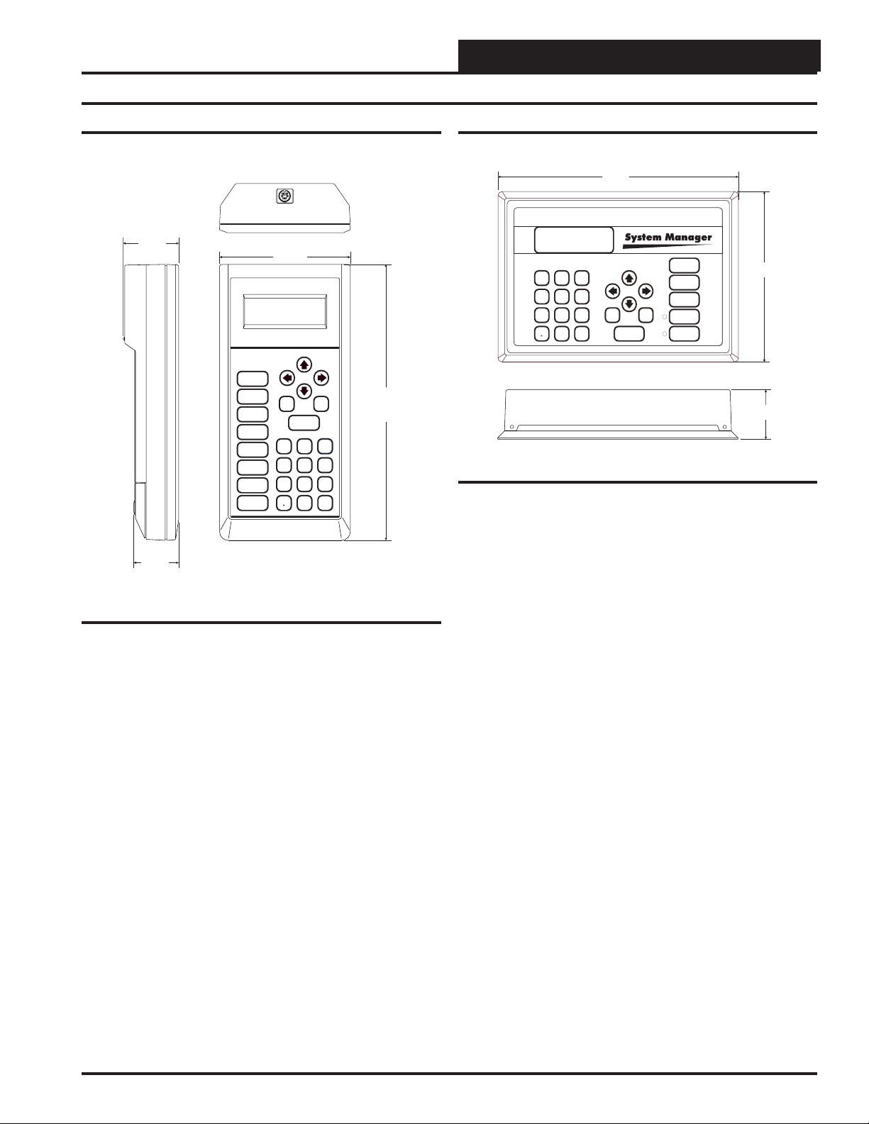
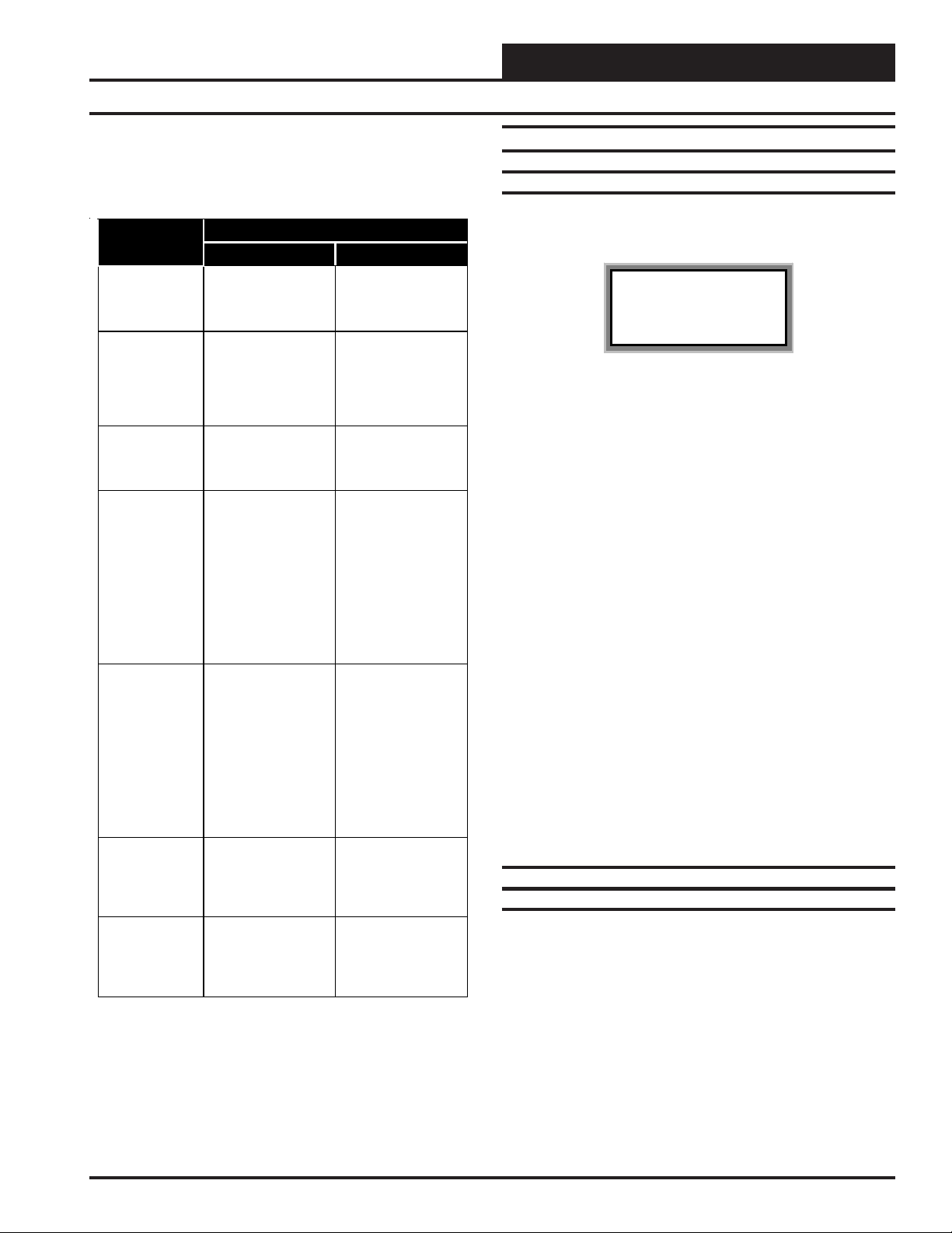
Modular Service Tool
2.02"
1.63"
Figure 1: Modular Service Tool Dimensions
Description
The OE391-05 Modular Service Tool is a system operator interface
that provides a direct link to enable the system operator to view the
status, configure and to adjust the setpoints of any controller on the
control system communications loop. The Modular Service Tool is
housed in an attractive beige colored plastic enclosure. The display
area is covered with a clear plastic bezel for protection of the display
screen. The Modular Service Tool has a four line by 20 character display panel with adjustable contrast control and a 27 key membrane
keypad for data selection and entry. All keypad operations are simple
and straight forward, utilizing non-cryptic plain English language
messages. Menu driven programming allows for easy setup and operation without the need for specialized training. The OE391-05 Modular Service T ool is supplied with (4) AA (1.5V) Volt alkaline batteries
a wall mount DC power supply and a communication cable terminated
with an 8 pin DIN connecter for connection to the Service Tool. The
cable allows the user to setup and program any WattMaster V AV controller with a 8 pin DIN connector socket by simply plugging in the
service tool to the socket on the controller. An adapter is also provided
to allow connection to the 3 pin communications terminal block on
controllers which do not have the 8 pin DIN connector.
The Modular Service Tool is designed to be carried by the system installer or service technician. Its rugged plastic housing, provides superior protection for the electronic components housed inside. The OE39105 Modular Service Tool is a top quality service tool that will stand up
to the demands of the typical job site environment for many years.
Mode
Selection
STATUS
SETPOINTS
SCHEDULES
OVERRIDES
ALARMS
CONFIGURATION
BALANCE - TEST
ON
4.75”
UP
PREV
ESC
13
4
708
DEC
NEXT
DOWN
CLEAR
ENTER
2
5
6
9
MINUS
-
10.00”
Modular System Manager
9.00"
13
2
5
6
4
708
9
DEC
MINUS
-
UP
PREV
ESC
DOWN
ENTER
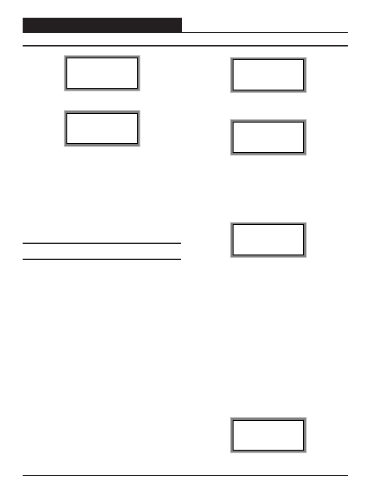
Figure 2: Modular System Manager Dimensions
Description
The OE392-05 – Modular System Manager provides a direct link to
enable the system operator to view the status and to adjust the setpoints
of any controller on the control system communications loop. The Modular System Manager is designed to be used with the WattMaster VAV
Control System. The System Manager is housed in an attractive offwhite colored plastic enclosure. The System Manager is equipped with
a four line by 20 character backlighted display panel and a 24 key membrane keypad for data selection and entry. All keypad operations are
simple and straight forward, utilizing non-cryptic plain English language
messages. Menu driven programming allows for easy setup and operation without the need for specialized training. The System Manager also
has 2 integral LED’s for user notification of system alarm conditions
and override initiations. Protection from unauthorized users is provided
by the System Manager’s integral multi-level passcode authorization
programming.
On W attMaster VAV Systems, the Modular System Manager is wired to
the communications and power loop of the system via a pigtail cable
with modular connectors on one end and stripped wire ends on the other
that is provided with the System Manager. This pigtail cable allows
connection of power to the Modular System Manager from a 24 VAC
power source and communications wiring from the HVAC unit controller communication wiring terminals.
The Modular System Manager is designed for wall mounting. Mounting holes are provided to attach the Modular System Manager to a standard handy box. It is recommended that the System Manager be mounted
at approximately eye level to allow for ease of programming and reading of the display. The System Manager is typically mounted in the
building manager or superintendent’s office or in an equipment room.
The attractive enclosure is quite suitable for mounting in any location
or with most decors.
STATUS
SETPOINTS
NEXT
SCHEDULES
CLEAR
OVERRIDES
ALARMS
6.25"
1.81"
Operator Interfaces 3
Page 4

Technical Guide
System Connections
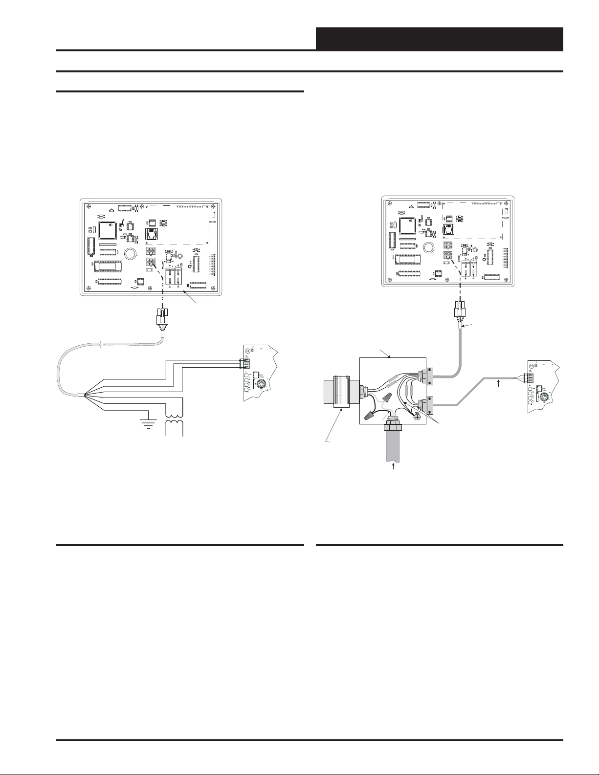
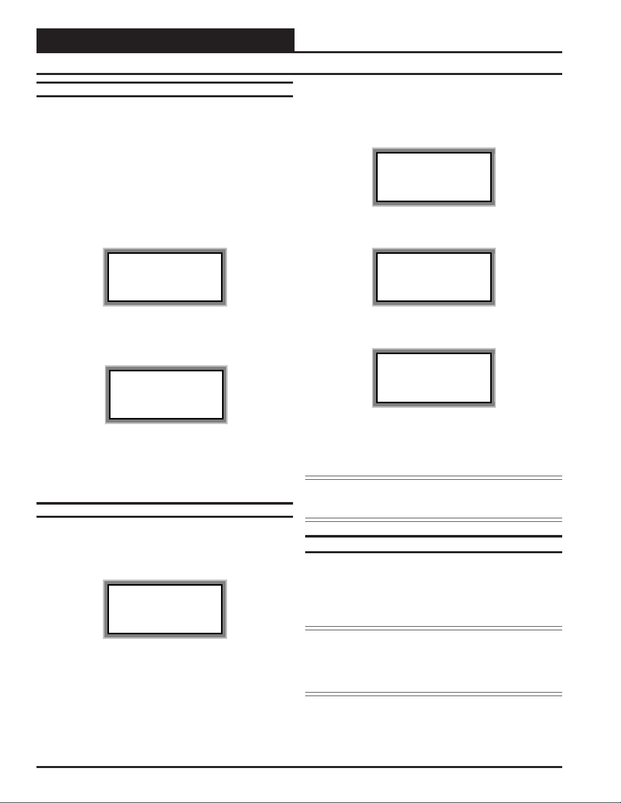
Modular Service Tool
W ether you have a S tand Alone, Interconnected or Networked System,
the Modular Service T ool always connects to an HVAC unit controller
via a prefabricated cable that is supplied with the service tool. The Modular Service T ool cable is terminated on both ends with a mini DIN connector. Attach one end to the Modular Service Tool and the other end to
the mini DIN connector on the HVAC unit controller. If this is an Interconnected System, all controllers that are interconnected with commu-
Optional Connection For
Controllers Without DIN Connector
Male DIN Connector
Connector Cable
nications cable can be programmed from any HVAC unit controller on
the loop. If this is a Networked System, all controllers on the entire
Networked System can be programmed from one HVAC unit controller.
Be sure that the Modular Service Tool has fresh batteries installed or
that it is connected to a power source using the supplied power pack
before attempting any programming of the controller. See Figure 3 for
connection details.
PL101904 Adapter Board
COMM
T
SHLD
R
Typical Controller Board
The Modular Service Tool Can Be Connected To Most
Controllers By Plugging One End Of The Supplied
Cable Into the Modular Service Tool DIN Connector
And The Other End Into The DIN Connector On The
Controllers.
Some Controllers Without DIN Connectors Require
Use Of The Supplied PL101904 Adapter Board Shown
Above. To Connect With Adapter Board, First Unplug
COMM Terminal Block From Controller Board. Plug
PL101904 Adapter Board Terminal End Into Terminal
Block Base On Controller. Plug DIN Connector Cable
Into DIN Connector On PL101904 Adapter Board . See
Optional Connection For Controllers Without DIN
Connector Above For Illustration Of This Connection.
erminal
T Block Base
(Remove Terminal Block)
Female DIN Connector
Figure 3: Modular Service Tool
Mode
Selection
STATUS
SETPOINTS
SCHEDULES
OVERRIDES
ALARMS
CONFIGURATION
BALANCE - TEST
ON
PREV
UP
NEXT
DOWN
CLEAR
ESC
ENTER
13
2
5
6
4
708
9
DEC
MINUS
-
Power On Button
Modular Service Tool
Be Sure The Modular Service
Tool Is Connected To The
Supplied Power Pack Or Has
Fresh Batteries Installed Before
Attempting Programming Of The
Controller. Be Sure The Power Is
Turned Off On The Modular
Service Tool Before Connecting
The Cable To The Controller.
4
Operator Interfaces
Page 5
Technical Guide
V62C518256L-70P
CX12
CX13
PCB80C552-5-16WPP442860=2/5
PDfD9722V7Y
PHILIPS
24C128
470uF50v
COMMOUT
COMMIN
MC34064A
74HC540
Modular System Manager
Back of Front Cover
P1
P2
VAR1
U13
RS-485P
COMM
R14
U6
V62C518256L-70PV62C518256L-70P
CX11
CX12
U12
U11
CX7
PAL
EPROM
RAM
CX13
75176
U8
74HC573
CX8
RN1
SC1
YS101830PREV.YS101830PREV.
2PMODULARPSYSTEM
MANAGER
PCB80C552-5-16WPP442860=2/5PCB80C552-5-16WPP442860=2/5PDfD9722V7YPDfD9722V7Y
C2
U7
X1
C1
R1
R4
EWDOGEWDOG
PHILIPS
X2
C3
PHILIPSPHILIPS
U3
CX5
R3
R9
8583
CX6
D3
U4
24C12824C128
CX4
74HC259
U1
U2
CX2
R3
R2
U14
C8
CX9
C7
470uF50v
1000uF10v
470uF50v
1000uF10v
R12
R11
COMMOUTCOMMOUT COMMINCOMMIN
D6
C4
R13
MC34064AMC34064A
U9
9936
D5
L1
U10
74HC540
CX14
C6
P3
CX10
C5
74HC92374HC923
R10
D4
CX3
82B71582B715
PJ1
D2
R6
R5
D1
U3
DSPY1DSPY1
R7
RV1
Class 2 Transformer
Rated For 6 VA Minimum
(By Others)
Handy Box , Conduit,
Fittings, Wire Nuts,
Butt Splices Etc.,
( By Others)
Controller Board
T
SHLD
R
HZ000121
Modular Pigtail Cable
Supplied With System Manager
WHITE(
T
)
B
LA
C
K
(R
)
RED(24 VAC)
BROWN(GND)
GREEN(
G
ND)
Drain Wire (Shld)
LINE
VOLTAGE
LINE VOLTAGE
2-Conductor Shielded
18-Guage
Communications Wire
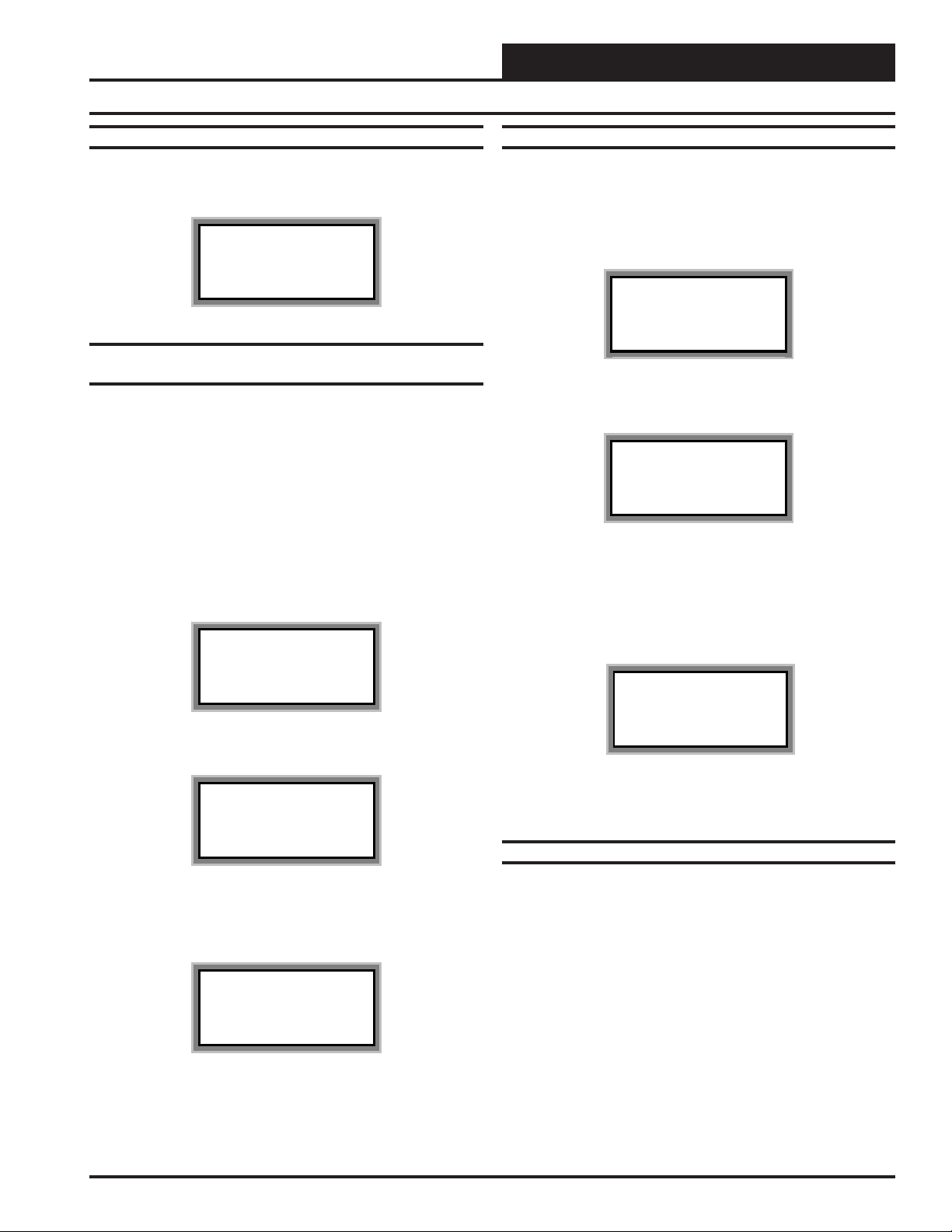
Modular System Manager
Power and communications are supplied to the System Manager via a
modular/pigtail cable that is supplied with the System Manager. This
cable has a male Molex connector on one end for connection to the
female Molex connector on the System Manager. On the other end are 5
insulated wires with a drain wire which are used for connection to the
YS101830PREV.
2PMODULARPSYSTEM
MANAGER
U1
74HC259
R1
R4
C1
X1
C2
U7
PAL
CX7
CX11
U11
CX12
U12
Use Supplied Modular
For Connection To Terminal
U2
EWDOG
CX4
U3
R3
PHILIPS
PCB80C552-5-16WPP442860=2/5
24C128
PDfD9722V7Y
PHILIPS
CX5
CX6
C3
8583
X2
U6
RN1
CX8
74HC573
U8
SC1
EPROM
RAM
V62C518256L-70P
Cable With Stripped Ends
Block And Transformer
WHITE (T)
DRAIN WIRE (SHLD)
BLACK (R)
RED (24 VAC)
BROWN (GND)
GREEN (GND)
CX2
R3
R2
U4
R9
D3
VAR1
CX13
75176
RS-485P
COMM
R14
Rated For 6 VA Minimum
DSPY1
U3
CX3
D1
R5
82B715
R6
D2
PJ1
COMMOUT
P1
COMMIN
P2
U13
R10
D5
R11
D4
R12
L1
CX10
U9
C4
9936
D6
MC34064A
C5
R13
CX9
1000uF10v
470uF50v
C6
C8
C7
1000uF10v
470uF50v
74HC540
CX14
Class 2 Transformer
RV1
R7
74HC923
U10
P3
U14
Modular System Manager
Back of Front Cover
T
SHLD
R
WMVAV Controller Board
Connection Shown
May Also Be Connected To Any
VAVBOX Controller On Loop
communication and power wiring from the transformer and from the
local loop communications terminal on the WMVAV controller or any
VAVBOX controller ’s communication terminal. A class II, 24 VAC
transformer (by others) rated at 6 VA or greater load capacity is required
for powering the System Manager.
See Figure 4 & 5 for System Manager connection and wiring details.
Figure 4 Schematic for Wiring System Manager
Using Modular Cable Pigtail
Operator Interfaces
Figure 5: Detailed Typical System Manager Wiring
Using Modular Cable Pigtail
5
Page 6
Technical Guide
General Programming Information
Operator Interfaces Comparison
In order to configure and program the W attMaster VAV System controllers you must have a central operators interface or a personal computer
with the Prism computer front end software installed. Two dif ferent central operators interfaces are available for programming of the W attMaster VA V Controls System. You may use either the Modular Service T ool
and/or the Modular System Manager to access the status and set-
points of any controller on your communications loop.
Mode
Selection
STATUS
SETPOINTS
SCHEDULES
OVERRIDES
ALARMS
CONFIGURATION
BALANCE - TEST
ON
Modular Service Tool
13
2
MINUS
PREV
6
9
-
4
708
DEC
5
Modular System Manager
UP
ENTER
DOWN
NEXT
CLEAR
2
5
6
9
MINUS
-
PREV
ESC
13
4
708
DEC
System Manager
UP
NEXT
DOWN
ENTER
CLEAR
ESC
STATUS
SETPOINTS
SCHEDULES
OVERRIDES
ALARMS
The Modular Service Tool or the System Manager allow the user to
view any temperature or output condition and change any setpoint to
fine tune the operations of the total system. All keypad operations are
simple and straightforward, utilizing non-cryptic plain English messages.
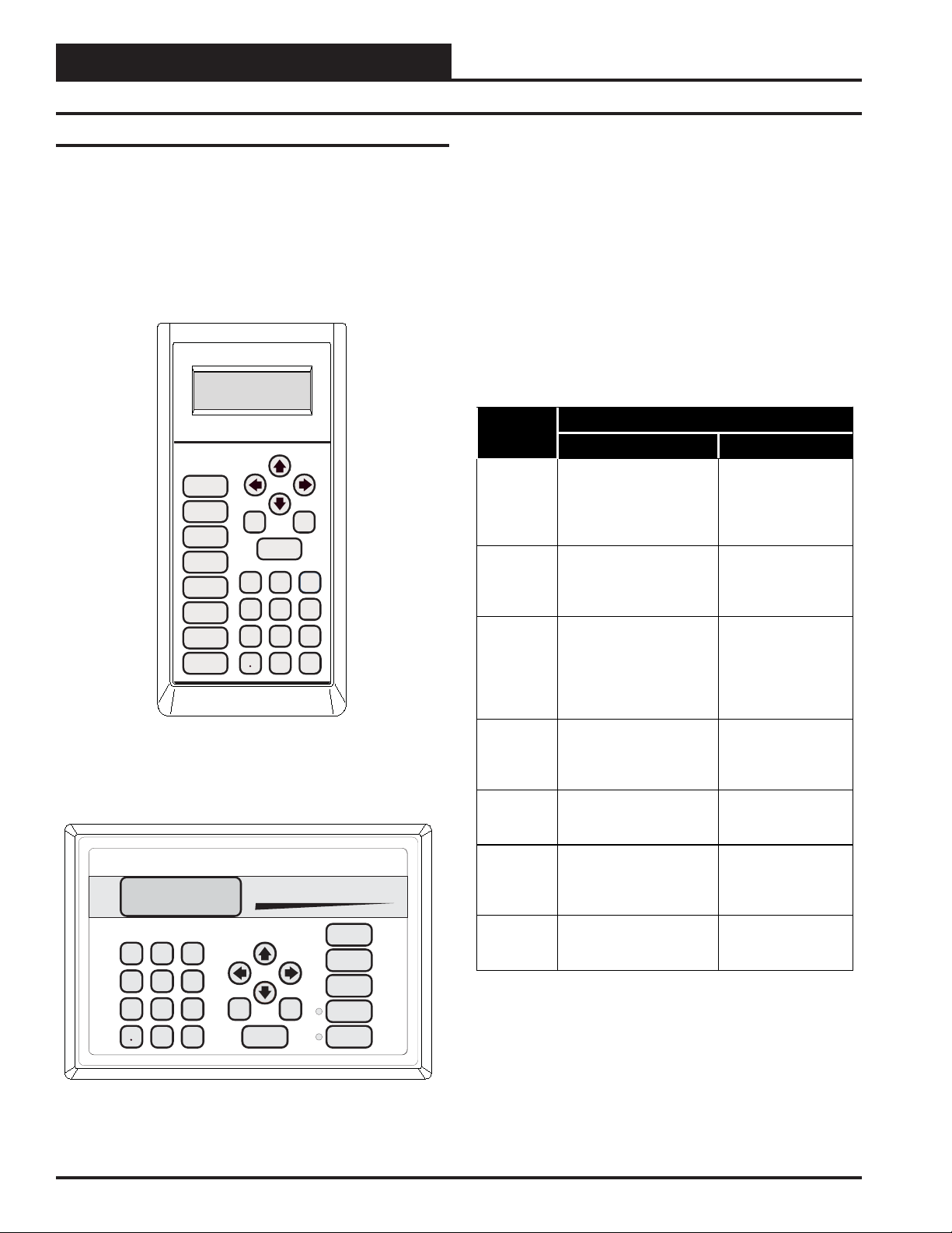
Display Screens & Data Entry Keys
The System Manager display screens and the Modular Service Tool
display screens are very similar. For most setpoints and modes the only
difference between using the Service T ool and the System Manager is a
few differences in the function of the keypads. In this manual where a
difference in the keypad input or the screens displayed exists between
the two operators interfaces, both screens or keypads will be shown.
See the chart below for a list of the keypad descriptions and functions.
Keypad
Description
ESC
System Manager Modular Service Tool
Used to exit from screens
or from data entry. Use
Key Function
Same f u nction as
System Manager
this screen to return to the
main menu f r om any
screen in the system
ENTER
This key is used to close a
data entry field and
Same f u nction as
System Manager
advance to the next item
or screen
Clear
If a data entry mistake is
made, press this key to
clear the data entry field
and start over
Same f u nction as
System Manager but
also turns off the
power to the Service
Tool when on the
main menu screen
Minus
If a setpoint with a
negative value is required,
Same f u nction as
System Manager
press this key for the
minus sign
DEC
Press this key when
entering data that requires
Same f u nction as
System Manager
a decimal point
⇐ ⇒
Steps the user to the next
controller on the loop on
Same f u nction as
System Manager
interconnected or
networked systems
⇑
⇓
Steps the user backward or
forward through the
screens
Same f u nction as
System Manager
Mode Selection Buttons
Both the System Manager and the Modular Service Tool are provided
with “Mode Selection Buttons” . These buttons give the user instant
access to the specific mode desired without having to scroll through
several menu screens to get there. The Modular Service Tool has 2
extra function keys (“Configuration” and “Balance-Test”) that are not
available on the System Manager.
6
Operator Interfaces
Page 7
Technical Guide
t
Service Tool And System Manager
Entering Unit ID (Address)
Button
Description
STATUS
SETPOINTS
SCHEDULES
OVERRIDES
ALARMS
CONFIGURATION
BALANCE-TEST
Notes:
Modular Service Tool System Manager
Pressing this button
takes you directly to
“Status” screens
Pressing this button
takes you directly to
“Setpoints” screens
Pressing this button
takes you directly to
“Schedules” scr een s
Pressing this button
takes you directly to
“Overrides” screen.
See the “Override
Button” section of
this manual for a
description of this
See Note 1 below.
Pressing this button
takes you directly to
“Alarms” screen.
See the “Alarms
Button” section of
this manual for a
description of this
See Note 1 below.
Pressing this button
takes you directly to
“Configuration”
Pressing this button
takes you directly to
Mode Selection Buttons
the controller
the controller
the controller
the controller
function.
the controller
function.
the controller
screens
the controller
“Balance-Test”
screens
Pressing this button
takes you directly to
the controller
“Status” screens
Pressing this button
takes you directly to
the controller
“Setpoints” and
“Configuration”
Menu
Pressing this button
takes you directly to
the controller
“Schedules” screens
Pressing this button
takes you directly to
the controller
“Overrides” screen.
See the “Override
Button” section of
this manualfor a
description of this
function.
See Notes 1 & 2
below.
Pressing this button
takes you directly to
the controller
“Alarms” screen.
See the “Alarms
Button” section of
this manual for a
description of this
function.
See Notes 1 & 2
below.
Not Available
Use “Setpoints”
Button To Access
Menu
Not Available
1.) This button only functions w hen the system is configured
for “Network Mode” or “Multiple MGRS Mode”. It will no
function in ‘Stand Alone M ode”.
2.) The “Search For Units” functio n must be p erformed on the
System Manager upon initial system setup before this function
will be available. See the “System Manager NM & MM Loop
Search” section of this manual for complete instructions on
performing a loop search.
With both the Modular Service Tool and the Modular System Manager
You must enter the ID (Address) of the controller you wish to program
Unit Selection
Enter Unit ID#
Selected ID#: xxxx
With the main menu screen displayed, press the function key associated
with the operation (setpoints, configuration, etc.) you want to perform.
The screen shown above will appear asking you to enter a unit I.D.#
(controller address). Put in the ID# of the controller you wish to communicate with then press the “ENTER” key.
If this is Multiple Loop Network System the Unit ID is actually two
separate numbers, combined into one value. The first part of the number contains the Loop Address at which the controller is located. The
second part of the number contains the actual controller address. See
Examples #1 & #2 below.
EXAMPLE #1
You would like to view the 3rd controller on the 5th loop. Enter “503”
as the Unit ID.
EXAMPLE #2
Y ou would like to view the 12th controller on the 24th loop. Enter “2412”
as the Unit ID
EXAMPLE #3
You would like to view the only controller on the loop. Enter 1 as the
Unit ID. No loop number is required since there is only one loop.
Hit the “Enter” key after entering the unit ID. If you are using the Modular
Service T ool you will be taken directly to the first screen for the operation you are trying to program.
Modular System Manager
System Manager Initialization Screens
When the System Manager is powered up, the first screen displays the
current version of the software installed in your System Manager and
whether your system is configured for Network or Stand-Alone operation. On a Networked System, all controllers on the communications
loop are available for programming by entering their loop address (ID).
If the System Manager is configured for Stand-Alone operation, only
the HVAC unit controller that the System Manger is connected to is
available for programming. The Stand-Alone feature is only used for
servicing and testing. For normal operation the System Manager must
be configured for Network mode.
Operator Interfaces
7
Page 8
Technical Guide
General Programming Information
Initializing
System Manager vX.XX
Wattmaster Controls
Network Mode
System Manager vX.XX
Monday Operations
09/09/99 04:26 PM
NM Outdoor Air 87°F
The screen above will appear a few seconds later. The last line of the
display will have the letters SA (Stand Alone Mode), MM (Multiple
System Manager Mode) or NM (Network Mode) followed by the current outdoor air temperature. The System Manager normally ships from
the factory set for NM (Network Mode). If you have only one System
Manager, the system must be set for NM (Network Mode). If you have
multiple System Managers on your system, the system must be set for
MM (Multiple System Managers Mode). If you believe your system is
incorrectly configured, please follow the instructions that follow. If your
system is configured correctly, proceed to the System Manager Network Mode Loop
Configuring For Stand-Alone Mode, Multiple
System Managers Mode or Network Mode
1) Set Time & Date
2) Communications
->) Next Menu
ESC) Exit Menu
Press the “2” key on the keypad to enter the communications screen.
THIS ACTION REQUIRES
A SPECIAL HIGH LEVEL
PASSCODE CLEARANCE
Enter: xxxxxxx
Enter the seven digit passcode “2337377” to access the next screen.
These seven digits spell the word “ADDRESS” on your telephone keypad if you forget what they are.
Y ou will then see the screen below displayed. You must use the keypad
to enter the correct number for the mode of operation needed for your
system.
0) Stand Alone
1-60) Multiple MGRS
63) Network System
Enter Mode Of Op:.xx
As previously described the System Manager must be configured for
the correct mode of operation for your system. Again, there are 3 modes
of operation available for the W attMaster VAV System. They are “Stand
Alone Mode”, “Multiple MGRS Mode” or “Network Mode”.
Look at the bottom line of the display as mentioned in the previous
paragraph and determine which one your System Manager is currently
set for. If you have a single System Manager for your entire system,
then you need to operate in “Network Mode” and the first two characters on the bottom line of the display should be “NM”. If you have
multiple System Managers on your system then you need to operate in
“Multiple MGRS Mode” and the first two characters on the bottom
line of the display should be “MM”. The System Manager should never
be set to “Stand-Alone” mode unless you have been instructed to configure this setting by WattMaster Technical Support.
If your display indicates a different mode than the one you need, press
the “Enter” key and the following screen will appear.
For “Multiple MGRS Mode” enter the address at which you want this
particular System Manager to be set. When multiple System Managers
are used on a local loop, each must be set with a unique address different from any other device on that loop. You must perform this same
operation again for each System Manager installed. If you want one of
these System Managers to be able to indicate alarms and overrides for
the entire system you must enter “63” for “Network Mode” on that
particular System Manager.
For “Network Mode” (or as explained above for Multiple System
Managers when one is to be set to indicate alarms and overrides) enter
“63”.
For “Stand Alone Mode” enter “0”.
Once you have the correct number per the display above displayed,
press the ENTER key. The following screen will appear telling you that
you have changed the system mode. Press any key on the keyboard to
exit this screen.
You Have Changed The
System Manager Mode
Press Any Key To
Continue
8
Operator Interfaces
Page 9

Technical Guide
System Manager NM & MM Mode Loop Search
When the System Manager is configured for Network Mode a loop search
must initially be performed for the System Manager to recognize alarms
or overrides. Also, when you have a system that has multiple System
Managers and you have one of the System Managers set to (63) Network Mode for alarm and override indication, you must also perform a
loop search for that System Manager. This allows the System Manager
to be aware of all alarms and overrides for all local loops on the entire
system. .
Note: The Loop Search function is only required when using
the System Manager(s), not the Modular Service Tool.
To access the Loop Search screen, do the following. From the main
menu screen press enter to display the following screen.
1) Set Time & Date
2) Communications
->) Next Menu
ESC) Exit Menu
Press the “Next” arrow key. The following screen will be displayed.
1) Change Passcodes
2) Loop Search
<-) Prev. Menu
ESC)Exit Menu
Once the search is completed the following screen will be displayed.
Loop Search
Finished
Loops Found = XX
Press ESC to Exit
The screen will display the number of loops found on your system. The
information will be saved into the System Manager’s memory. No further loop searches will be required unless an additional MiniLink Polling Device is added to the Network System.
System Manager Alarm Search
The System Manager can be used to search for all active alarms on the
system. The MiniLink PD must be configured to allow for “Alarm Polling” for each controller that alarming is desired on for this function to
work. See the MiniLink PD programming section of this manual for
setting information. Press the “Alarm” key. The Unit Selection screen
below will be displayed. Enter the Unit ID of any unit on the system and
press “Enter”. This is the unit ID of where the alarm search begins. The
entire system is searched from this point.
Unit Selection
Enter Unit ID#
Selected ID#: xxxx
The following screen will appear. The System Manager will search for
any active alarms on the entire system.
Press the “2” .The following screen will be displayed.
Loop Search
Current Loop = XX
Loops Found = XX
Searching
The System Manager will now proceed to search all loops to find the
MiniLink Polling Devices that are connected to the system. The screen
will display the current loop being searched and the number of loops
currently found.
Alarm Screen
SEARCHING!
After the System Manager completes it’s search, it will list the first unit
on the system that currently has an active alarm. Press “Enter” to scroll
through all the alarms on that particular unit. T o move to the next unit or
back to the previous unit use the “Prev” or “Next” arrows to move between units with alarms.
Alarm Search Screen
Loop = 1 Unit = 59
Space Sensor Failure
T o clear any alarms that are found you must fix the problem indicated in
the alarm. Once the problem is fixed, the alarm will clear from the screen
the next time the unit is polled.
Operator Interfaces
9
Page 10
Technical Guide
General Programming Information
System Manager Override Search
When a space sensor with override option is used with any VAVBOX
controller or WMVAV controller, the System Manager can determine
and report any controllers which are currently operating in an override
condition. The MiniLink PD must be configured to allow for “Alarm
Polling” for each controller that alarming is desired on for this function
to work. See the MiniLink PD programming section of this manual for
setting information
To access the Space Sensor Overrides screen, press the “Override” button located on the System Manager . A screen will appear asking you to
enter a unit ID. Enter an ID for any active controller on the system and
press "Enter". The following screen will appear.
Overrides Screen
SEARCHING!
After the System Manager completes its search, it will list the first unit
on the system that is currently in the override mode. Press the previous
or next button to scroll through all units that are in the Override Mode.
Overrides Screen
Loop = 1 Unit = 59
Override Unit
If you wish to change either Level 1 or Level 2 passcodes please see the
instructions that follow.
From the main status screen press "Enter", The following screen will
appear.
1) Set Time & Date
2) Communications
->) Next Menu
ESC) Exit Menu
Press the “Next” arrow key. The following screen will be displayed.
1) Change Passcodes
2) Loop Search
<-) Prev. Menu
ESC)Exit Menu
Press the “1” .The following screen will be displayed.
Enter New Passcode
Level 1.....: xxxx
Level 2.....: xxxx
[Must Be 4 Digits]
Anytime you enter a unit ID with the Modular System Manager you
will be asked for a passcode. Passcodes are not required to view Status
Screens. The screen below will appear if this action requires passcode
clearance.
System Manager Passcodes
Anytime you enter a unit ID with the Modular System Manager you
will be asked for a passcode. Passcodes are not required to view Status
Screens. The screen below will appear if this action requires passcode
clearance.
THIS ACTION REQUIRES
PASSCODE CLEARANCE
Enter Passcode: xxxx
The System Manager has two levels of user access. Level 1 users are
limited to viewing or changing the Time, Date, Operating Schedules
and Heating and Cooling Setpoints. Level 2 users have complete system access. Any status or setpoint field can be read or reset from the
System Manager.
This screen allows you to enter new Level 1 or Level 2 passcodes. The
actual digits in your passcodes are never displayed. An “X” is used as a
place holder for each digit entered. Passcodes must always be four digits in length, so the usable range of numbers is 1000 to 9999.
Caution: If you change the Level 2 passcode and cannot
remember what it is, you will be locked out of
your system!
Modular Service Tool
The Modular Service Tool is very similar to the System Manager in its
operations as stated previously. Two exceptions to this are that the Service Tool unlike the System Manager does not check the entire system
when performing an “Alarm” or “Override” search and it does not have
any passcoding capability.
Note: When the Alarms or Overrides buttons are pressed on
the Modular Service Tool it will search only the loop
number of the unit ID that has been entered, therefore
each local loop must be searched individually to access
all alarms or overrides on the system.
These two levels of passcodes are programmable by any Level 2 user.
The default Level 1 passcode is “111 1” and the default Level 2 passcode
is “2222.”
10
Operator Interfaces
Page 11
Technical Guide
Modular Service Tool Initialization Screen
After connecting the Service Tool to the controller with the supplied
cable, press the “On” key. The following screen will appear.
Service Tool vX.XX
Monday Operations
09/09/02 04:26 PM
Stand Alone Mode
Configuring The Modular Service Tool For
Network Or Stand-Alone Operation
As with the System Manager described previously, you must determine
if the mode displayed is correct for your system. Normally for most
applications the words “Network Mode” should be displayed in the
window. If it has been configured for Stand Alone mode you will see
the words “Stand Alone Mode” on the bottom line of the display. S tand
Alone Mode is only used when servicing or troubleshooting and is normally not used for general setup and programming as it only allows the
user to access the controller it is attached to and not the entire networked system
If your display indicates a different mode than the one you need, press
the "Enter" key and the following screen will appear.
1) Set Time & Date
2) Communications
3) Energy Saving
ESC) Exit Menu
Press the “2” key on the keypad to enter the communications screen.
Modular Service Tool Alarm Search
First, press the “Alarm” key. The Unit Selection screen below will be
displayed. Enter the Unit ID of any controller on the system and press
“Enter”. This is the unit ID of the loop where the alarm search will be
done. Unlike the System Manager, only the alarms on this loop will be
searched, not the entire system.
Unit Selection
Enter Unit ID#
Selected ID#: xxxx
The following screen will appear. The System Manager will search for
any active alarms on the local loop.
Alarm Screen
SEARCHING!
After the Modular Service T ool completes it’ s search, it will list the first
unit on the local loop, whose ID was entered, that currently has an active alarm. Press “Enter” to scroll through all the alarms for controllers
on that particular loop. To move to the next controller or back to the
previous unit use the “Prev” or “Next” arrows to move between controllers with alarms on the loop.
Alarm Search Screen
Loop = 1 Unit = 59
Space Sensor Failure
0) Stand Alone
1) Network System
Enter Mode Of Op:.xx
As the screen indicates, press the right or left arrow keys to select the
proper mode of operation. When you are finished press “Enter” to
move back to the main menu screen.
You Have Changed The
System Mode
Press Any Key To
Continue
Operator Interfaces
T o clear any alarms that are found you must fix the problem indicated in
the alarm. Once the problem is fixed, the alarm will clear from the screen
the next time the unit is polled.
Modular Service Tool Override Search
When a space sensor with override option is used with any VAVBOX
controller or WMVAV controller, the Modular Service Tool can determine and report any controllers which are currently operating in an override condition on the local loop whose ID (Address) has been entered
before running the search.
T o access the Space Sensor Overrides screen, press the “Override” button located on the Modular Service Tool . A screen will appear asking
you to enter a unit ID. Enter an ID for any active controller on the
particular local loop you wish to search and press "Enter". Unlike the
System Manager, only the overrides on this loop will be searched, not
the entire system. The following screen will appear .
11
Page 12

Technical Guide
Programming The WMVAV Controller
Configuration
In order to correctly setup the WMVAV controller you must first configure several parameters in regard to the type of HV AC unit and system
you have installed. Most of these values and operating parameters are
only set once, at the initial system setup and are never changed.
System Manager Instructions
From any menu screen press the “Setpoint” key. The unit selection screen
will appear requesting that you enter the unit ID number. Enter the cor rect unit ID number of the WMVAV controller you want to configure
and hit the “Enter” key. You will see the screen shown below.
1)Change Setpoint
2)Configure Unit
3)Damper Force
ESC) Exit Menu
Press “2” on the keypad to enter Configuration Screen #1.
Modular Service Tool Instructions
From any menu screen press the “Configuration” key. The unit selection screen will appear requesting that you enter the unit ID number.
Enter the correct unit ID number of the WMVA V controller you want to
configure and hit the “Enter” key. You will then see unit configuration
screen #1.
lected as the Controlling T emperature for the WMVAV controller. A vailable selections are:
SUPPL Y AIR Supply Air Sensor
(Occupied Cooling with
Morning W arm-up)
*RETURN AIR Return Air Sensor
(Occupied Cool, Heat &
Vent)
SPACE TEMPERATURE Space T emperature Sensor
(Occupied & Unoccupied
Cool, Heat & Vent)
OUTSIDE AIR Outdoor T emperature Sensor
(Occupied Cool, Heat &
Vent)
LOCAL ANALOG V ALUE Local Analog V alue
* On WMVAV controller codes earlier than version 1.01, if you
select “RETURN AIR” you will have Occupied Cool, Heat &
Vent as opposed to Occupied Cooling & Venting Only as the
previous code provided.
Configuration Screen #3
WMVAV Config ID 59
Economizer Control
By This AHU: YES
[0=NO 1=YES]
Configuration Screen #1
WMVAV Config ID 59
Constant Volume Mode
Active : NO
[0=NO 1=Yes]
This HVAC unit can be configured to operate as a Constant Volume or
VA V unit. The Constant Volume Mode does not provide Static Pressure
Control. You can install a Duct Pressure Sensor on a Constant Volume
unit and only monitor the Static Pressure. This is the only mode that
supports dehumidification.
Configuration Screen #2
WMVAV Config ID 59
Controlling Sensor
SUPPLY AIR
Press”0” to Change
Press the “0” key to select the desired method of control and the third
line of the display will change text to show which sensor has been se-
If your AHU has outside air dampers, it is recommended that you allow
the WMVAV controller to modulate these dampers in the economizer
mode so that it can be used as the first stage of cooling. If you don’t
have outside air dampers, or you decide to let a separate controller maintain these dampers, select NO for this option.
Configuration Screen #4
WMVAV Config ID 59
Fan Cycle Mode
Needed: Yes
[0=NO 1=Yes]
If you need proof of airflow before allowing any heating or cooling
stages to operate, install a differential pressure switch with a contact
closure that is connected to analog input #7 and select this option. If
this option is not selected, the WMVAV controller assumes there is adequate airflow anytime the fan is running and ignores this signal.
12
Operator Interfaces
Page 13

Technical Guide
Configuration Screen #5
WMVAV Config ID 59
Proof of Flow Switch
Installed: No
[0=NO 1=Yes]
If you need proof of airflow before allowing any heating or cooling
stages to operate, install a differential pressure switch with a contact
closure that is connected to analog input #7 and select this option. If
this option is not selected, the WMVAV controller assumes there is adequate airflow anytime the fan is running and ignores this signal.
Configuration Screen #6
WMVAV Config ID 59
OA Humidity Sensor
Installed: No
[0=NO 1=Yes]
If your economizer control requires the use of the W etbulb T emperature
to enable or disable it, you must install a humidity sensor on analog
input #5 and select this option. If you require the Remote Signal to
determine the occupied mode of operation, you will need to move the
remote signal to Input #2 on the Analog Input Expansion Board.
Configuration Screen #7
Configuration Screen #9
WMVAV Config ID 59
Relief Pr. Control
Reverse Acting: No
[0=NO 1=Yes]
The Relief Pressure Control described in the previous paragraph can be
configured for reverse acting operation by setting this selection to “Y es”.
With the standard configuration (“No”) a relief fan VFD and/or Exhaust Damper would modulate towards its maximum high speed and/or
open position to decrease building pressure. If you select reverse acting
operation (“Y es”) on a decrease in building pressure the HVAC unit OA
damper would be modulated towards its maximum open position to
increase building pressure.
Configuration Screen #10
WMVAV Config ID 59
Reset Setpoint Using
Input Voltage Signal
Press “0” To Change
Press the “0” key to select the desired method of resetting the Cooling
and Heating Mode Supply Setpoint and the third line of the display
will change text to show what type of method has been selected to control the Reset Setpoint. Available selections are:
WMVAV Config ID 59
Dehumidification
Installed: No
[0=NO 1=Yes]
Y ou can monitor a wet contact closure on the first binary input on the 4
Binary Input expansion board and whenever it closes, the Gas Reheat
relay will be activated. This assumes you are in a cooling mode. The
Gas Reheat does not activate if the WMVAV controller is in the heating
mode. The option is only available on units that are configured for Constant Volume Mode. If you are controlling static pressure (VAV Mode)
then this option is ignored.
Configuration Screen #8
WMVAV Config ID 59
Relief Pr. Control
Installed: No
[0=NO 1=Yes]
If you need to control building pressure, select this option by entering a
‘1’ and connect the Relief Pressure Sensor to the Analog Expansion
Input #4. The Relief Fan VFD Signal is also found on the Analog Input
Expansion module as the only analog output on that board.
Input V oltage Signal
Outdoor Air Sensor
Space Sensor
Fan VFD Percentage
Local Analog Value
Return T emp Sensor
Configuration Screen #11
WMVAV Config ID 59
CO2 Sensor Installed
Sensor Type: 0
[0=NONE 1=ma 2=vdc]
You can install a CO2 Sensor on this HVAC unit to monitor the Carbon
Dioxide levels and/or to provide for Indoor Air Quality (IAQ) control.
If you just want to monitor the level, enter the same Maximum Economizer Position that you set for the Minimum Position and it will not be
reset as the CO2 level increases. If you do want IAQ control, set the
desired Maximum Economizer Position to reset up to during high levels of CO2. The factory supplied sensor provided for the CO2 readings is
a 0-10 VDC, 0 to 2000 PPM sensor. Be sure you enter a “2” if you are
using the default sensor.
Operator Interfaces
13
Page 14

Technical Guide
A
Programming The WMVAV Controller
Configuration Screen #12
WMVAV Config ID 59
CO2 Sensor Maximum
Reading: 2000 PPM
Enter 0 If No Sensor
If you install the default CO2 sensor, it will be a 0-10 VDC device that
provides 0-2000 PPM readings. Make sure this is set to the 2000 PPM
level unless you have installed your own sensor with a different scaling
range.
Configuration Screen #13
WMVAV Config ID 59
ir to Air Heat Pump
Control: NO
[0=NO 1=YES]
The WMVAV controller can be configured to operate as an Air To Air
Heat Pump Controller. If you make this selection, the same relays are
used to stage the compressors in both the heating and cooling modes.
The only difference is that a separate Reversing Valve relay will activate in the heating mode to enable heating to occur. You must configure
at least one relay for the reversing valve.
You can also configure for an Auxiliary Heat relay that will activate
whenever the supply air drops below the supply setpoint by 5°F, to
provide heat when the outdoor air is too cold for the heating mode to
operate correctly.
Configuration Screen #16
WMVAV Config ID 59
Broadcast Supply
Temperature: NO
[0=NO 1=YES]
This enables the WMVAV Controller to send its supply air temperature
reading to all controllers that do not have there own sensor on the local
loop. This is standard for VAVBOX applications.
Configuration Screen #17
WMVAV Config ID 59
Broadcast Humidity
Reading: NO
[0=NO 1=YES]
This enables the WMVAV Controller to send its relative humidity reading to all other controllers on the entire system. It is specifically used
when more than one HVAC unit is installed, and only one relative humidity sensor is used to supply its signal to all controllers.
Configuration Screen #18
WMVAV Config ID 59
Broadcast Internal
Schedule: NO
[0=NO 1=YES]
Configuration Screen #14
WMVAV Config ID 59
Broadcast Time Clock
to Loop Units: NO
[0=NO 1=YES]
This enables the WMVAV Controller to send its real time clock information to all controllers on the local loop. This must be used when
connecting VAVBOX Controllers on the local loop, but can be used to
synchronize clock time in all controllers on the local loop.
Configuration Screen #15
WMVAV Config ID 59
Broadcast Outside
Temperature: NO
[0=NO 1=YES]
This enables the WMVAV Controller to send its outdoor air temperature reading to all other controllers on the entire system. It is specifically used when more than one HVAC unit is installed, and only one
outdoor air sensor is used to supply its signal to all controllers.
This enables the WMVAV Controller to send its Occupied and Unoccupied status to the VAVBOX Controllers on the local loop.
Configuration Screen #19
WMVAV Config ID 59
Broadcast Status
Fan & Heat: NO
[0=NO 1=YES]
This enables the WMVAV Controller to send status information on
whether the HVAC unit main fan is running, or if it is in heat mode, to
the VAVBOX Controllers on the local loop. This enable is required
when VAVBOX Controllers have heating stages or are fan-powered.
14
Operator Interfaces
Page 15

Configuration Screen #20
Technical Guide
WMVAV Config ID 59
Broadcast VAV Boxes
Force To Max: NO
[0=NO 1=YES]
When “1=YES” is selected all VAVBOX controllers connected to this
WMVAV controller will be forced to their “Maximum Airflow” position during the Morning W arm-up mode of operation. Select “0=NO” if
you do not want this to occur. See the VAVBOX controller setpoint
screens for setting of the “Maximum Airflow” position.
Configuration Screen #21
WMVAV Config ID 59
Broadcast VAV Boxes
Force To Fix: NO
[0=NO 1=YES]
When “1=YES” is selected all VAVBOX controllers connected to this
WMVAV controller will be forced to their “Fixed Airflow” position
during the Morning W arm-up mode of operation. Select “0=NO” if you
do not want this to occur. See the VA VBOX controller setpoint screens
for setting of the “Fixed Airflow” position.
Configuration Screen #22- #41
Available Relay
Configurations
Heat Stage
Cool Stage On/Off Control Of A Cooling Stage
Rev Valve On/Off Contro l Of A Reversing Valve
Exhaust Fan
Re-Heat On/Off Control O f A Re-heat Device
Warm-up Mode
Pre-heater On/Off Control Of A Pre-heat Device
Economizer On/Off Control Of An Economizer
Alarm Relay On/Off Indication Of Alarms
Override
Occupied On/Off Indication Of The Unit Being
On/Off Control Of A Heating Stage
On/Off Con trol Of An Exhaust Fan or
WattMaster Controlled VAV Boxes To
On/Off Indication O f T h e Unit Being
Description Of Use
(8 Stages Max)
(8 Stages Max)
Exhaust Damper
On/Off Signal That Causes
Drive Open to Maximum Airflow
In Override Mode
In Occupied Mode
WMVAV Config ID 59
Stage Configurations
Rly xx: Not Used
Press “0” to Change
The following 20 screens allow you to set the four relays on the WMVA V
controller board and up to sixteen additional relays when relay expansion board(s) are used.
The first relay on the WMVAV controller is always reserved for the
Supply Fan. The remaining four relays on the main board and the additional sixteen relays on the expansion relay modules can be configured
by pressing the “0” key to change the relay to the desired configuration.
Available relay configurations are listed in the table that follows.
The WMVAV controller does not require that you start configuring your
heating or cooling stages first and it doesn’t require that you utilize
consecutive relays until all heating or cooling stages have been defined.
All relays can be used for any of the above options in any order you
desire. This method allows the greatest flexibility in the field, but it
requires close attention to the wiring of the heating and cooling stages
to prevent incorrect and possibly harmful operation.
The controller assumes there will only be one relay configured for Morning Warm-up Mode although it doesn’t prevent multiple relays from
being selected. Since this relay is used to send a signal to VAV boxes to
drive to their maximum airflow position, redundant relays are not required.
Relays #2 through #21 can be individually configured. This should be
enough to handle up to 8 stages of heating and 8 stages of cooling on
large HVAC units. Only the heating and cooling relays can be configured with multiple outputs. If any other option is selected more than
once, it will simply activate redundant relays but no multiple staging
will occur.
Operator Interfaces
15
Page 16

Technical Guide
Programming The WMVAV Controller
Setpoints
System Manager Instructions
From any menu screen press the “Setpoint” key. The unit selection screen
will appear requesting that you enter the unit ID number. Enter the cor rect unit ID number of the WMVAV controller you want to change
setpoints for and hit the “Enter” key. You will see the screen shown
below.
1)Change Setpoint
2)Configure Unit
3)Damper Force
ESC) Exit Menu
Press “1” on the keypad to enter the first unit setpoint screen.
Modular Service Tool Instructions
From any menu screen press the “Setpoint” key. The unit selection screen
will appear requesting that you enter the unit ID number. Enter the cor rect unit ID number of the WMVAV controller you want to change
setpoints and press the “Enter” key. You will then see setpoint screen
#1.
Setpoint Screen #1
WMVAV Spts ID 59
HVAC Mode Setpoints
Cooling......: xx°F
Heating......: xx°F
If the controller is configured for Space T emperature, Return Air T emperature or Return Air with Day Heating control, the unit attempts
to maintain these Cooling and Heating setpoints.
If you are using a remote BAS to activate the heating or cooling modes
with contact closures on the binary input board, set these two setpoints
to zero and select the supply air as the controlling sensor.
Setpoint Screen #2
WMVAV Spts ID 59
Unoccupied Setbacks
Cooling SetUp: xx°F
Heating SetBk: xx°F
During the unoccupied mode these values will be added to the cooling
setpoint and subtracted from the heating setpoint. These settings are
only used if the controller has been configured to utilize a Space T em-
perature Sensor.
De sc rip tion Minimum Default Maximum
Cooling SetUp
He atin g S e tB k
Setpoint Screen #3
WMVAV Spts ID 59
HVAC Mode Select
Deadband....: xx.x°F
The HVAC Mode Select Deadband is the amount of error from set-
point required to activate the heating or cooling mode of operation.
This assumes the Return Air or Space Temperature are the controlling
sensors. If the Supply Air is the controlling sensor then this setpoint is
not used.
De sc r iption Minimum Default Maximum
Deadba nd
F10
0
°
F0
0
°
°
0.1
F1.0
F30
°
F-30
°
°
F 10.0
F
°
F
°
°
F
16
De sc rip tion Minimum Default Maximum
Coo lin g
Heating
F74
0
°
0
F65
°
F90
°
F90
°
F
°
F
°
Setpoint Screen #4
WMVAV Spts ID 59
Supply Air Setpoints
Cooling....: xx°F
Heating....: xx°F
This is the Supply Air Temperature that the HV AC unit will try to maintain when in heating or cooling mode. The Heating Supply Air Setpoint
will also be used for the Morning Warm-up Supply Air Temperature.
De sc rip tion Minimum Default Maximum
Coo lin g
Heating
F55
50
°
60
F140
°
F70
°
F200
°
F
°
F
°
Operator Interfaces
Page 17

Technical Guide
A
A
Setpoint Screen #5
WMVAV Spts ID 59
Both Heating/Cooling
Supply Control Use
Deadband Of.: xx°F
All heating and cooling stages are staged up and down based on the
Heating/Cooling Supply Control Staging Deadband setpoint that is entered on this screen. The value that is entered here will be added to the
Supply Air T emperature Setpoint to determine the high end of the range
and subtracted from the Supply Air Temperature Setpoint to determine
the low end of the range. Staging of Heating/Cooling will occur above
and below this deadband range. When the temperature is within this
deadband range, no staging will occur.
Description Minimum Default Maximum
Deadband
0°
F1° F20° F
Setpoint Screen #6
WMVAV Spts ID 59
Morning WarmUp Setup
Target Temp: xx°F
Max Length.: xxx Min
Setpoint Screen #7
WMVAV Spts ID 59
Outdoor Air Lockouts
Cooling:.....: xx°F
Heating:.....: xx°F
If the Outdoor Air T emperature drops below the Cooling lockout setpoint by 1°F, the DX cooling will be locked out until the Outdoor Air
Temperature rises 1°F back above the lockout setpoint. The same 1°F
deadband applies to the Heat lockout setpoint except the Outdoor Air
locks out the heating when it is above the lockout instead of below the
lockout.
De sc riptio n Minimum Default Maximum
Cooling
Hea tin g
F50
-30
°
50
F75
°
F80
°
F90
°
F
°
F
°
Setpoint Screen #8
WMVAV Spts ID 59
ll Cooling Cuts Off
If Supply Air Temp
Drops Below: xx°F
If you need a Morning Warm-up period on your HVAC unit enter a
Target Temp you want the Return Air Temperature to achieve and the
Max Length of time you want to spend in warm-up mode trying to
achieve the target temperature. If you don’t need morning warm-up,
simply ignore the Target Temp setpoint and enter a ‘0’ for the Max
Length value.
De sc rip tion Minimum Default Maximum
Target Temp
Max Length
F72
50
°
0
Min 60 Min 240 Min
F90
°
F
°
If the Supply Air Temperature ever drops below this value, all cooling
stages are immediately cutoff, regardless of run time. If the economizer
is being controlled, it is also closed completely to prevent freezing.
Description Minimum Default Maximum
Low Cutoff
30°
F40° F60° F
Setpoint Screen #9
WMVAV Spts ID 59
ll Heating Cuts Off
If Supply Air Temp
Exceeds....: xxx°F
If the Supply Air T emperature ever exceeds this value, all heating stages
are immediately cutoff, regardless of run time.
Description Minimum Default Maximum
High Cutoff
60°
F 170° F250° F
Operator Interfaces
17
Page 18

Technical Guide
Programming The WMVAV Controller
Setpoint Screen #10
WMVAV Spts ID 59
Heating Stages Off
If Supply Fan VFD Is
Below:.........: xx%
If the Supply Fan VFD drops below this value, the heat will stage off.
The Supply Fan VFD will not be allowed to drop below this value while
the unit is in Heating Mode unless the static pressure rises 0.5” above
the static setpoint.
Desc ription Minimum Default Maximum
Below SP 0 % 30 % 100 %
Setpoint Screen #11
WMVAV Spts ID 59
Pre-Heat Output ON
Continuous Below OAT
Level........: xx°F
If your air handler has at least one heating stage and you require a low
ambient protection or preheating of the air stream, you can enter a supply temperature value that causes one stage of heating to come on and
remain on continuous if the outdoor air drops below this level. If you
don’t want this protection do not configure any relays for this function.
Setpoint Screen #13
WMVAV Spts ID 59
Economizer Setpoints
Min Position.: xx %
Control Rate.: xx
If the Economizer is not enabled or currently required during the occupied mode of operation, the outside air dampers will maintain the Min
Position setpoint to provide ventilation into the space.
The Control Rate can be used to speed up or slow down the operation
of the outside air dampers to prevent hunting. Unless you actually witness this damper hunting it is not recommended that the Control Rate
value be changed. Large values speed up the damper, and small values
slow down the damper.
Des cr iption Minimum Default Maximum
Min Position 0 % 10 % 100 %
Control Rate 10 90 99
Setpoint Screen #14
WMVAV Spts ID 59
Static Spt..: x.xx”
Deadband....: x.xx”
Control Rate: xx Sec
Description Minimum Default Maximum
Low Ambi e nt Leve l
-50°
F0° F70° F
Setpoint Screen #12
WMVAV Spts ID 59
Economizer Setpoints
OAT/WB Enable: xx°F
If the Outdoor Air Temperature drops below the OAT/WB Enable
(Outdoor Air Temperature or the optional Wetbulb Temperature, if
it’s available), the Economizer will be enabled to operate as the first
stage of cooling anytime there is a demand for cooling. If the economizer is currently in a control mode, it will attempt to maintain the
Supply Air Temperature at the Supply Air Cooling Setpoint.
Description Minimum Default Maximum
OAT/WB Enable
-30°
F55° F80° F
The WMVA V controller uses the Fan VFD signal to maintain the Static
Spt (duct static pressure) value plus or minus the Deadband value.
Adjustments to the signal are made at a rate equal to the Control Rate
setpoint, which can be used to speed up or slow down the signal to
prevent hunting.
Description Minimum Default Maximum
Static Spt 0.10” WG 0.50” WG 3.0” WG
Deadband 0.01” WG 0.10” WG 1.0” WG
Control Rate 1 Sec 10 Sec 30 Sec
18
Operator Interfaces
Page 19

Technical Guide
Setpoint Screen #15
WMVAV Spts ID 59
Relief Spt..: x.xx”
Deadband....: x.xx”
The WMVAV controller uses the Relief Fan VFD signal to maintain the
Relief Spt value plus or minus the Deadband value. Adjustments to the
signal are made at a rate equal to the Control Rate setpoint on the
previous Static Pressure screen. If you don’t require relief pressure control, simply ignore these settings.
Description Minimum Default Maximum
Relief Spt -0.20” WG 0.10” WG +0.20” WG
Deadband 0.01” WG 0.02” WG 0.10” WG
Setpoint Screen #16 & 17
WMVAV Spts ID 59
Set SAT Cool Reset
VLT=0V Spt=55
VLT=10V Rst=55
WMVAV Spts ID 59
Set SAT Heat Reset
VLT=0V Spt=140
VLT=10V Rst=140
VFD Percentage Cool Reset Example:
VFD Percentage (VFD) = 70% SAT Setpoint (Spt) = 55 F
VFD Percentage (VFD) = 30% SAT Setpoint (Rst) = 65 F
VFD Percentage Heat Reset Example:
VFD Percentage (VFD) = 30% SAT Setpoint (Spt) = 90 F
VFD Percentage (VFD) = 70% SAT Setpoint (Rst) = 120 F
Input Voltage Cool Reset Example:
Input Voltage (VLT) = 0 Volts SAT Setpoint (Spt) = 55 F
Input Voltage (VLT) = 10 Volts SAT Setpoint (Rst) = 65 F
Input Voltage Heat Reset Example:
Input Voltage (VLT) = 0 Volts SAT Setpoint (Spt) = 90 F
Input Voltage (VLT) = 10 Volts SAT Setpoint (Rst) = 120 F
Setpoint Screen #18
WMVAV Spts ID 59
Start Fan Delay
Timer...:10 Sec
This is the amount of time that the main HVAC unit fan will delay
before starting after an occupied signal is initiated or after a power failure. The default value is 999. With the default value the delay will be
equal to the unit address multiplied by 5.
Example: Controller ID (address) 18 would cause a 90 second delay
when the default value of 999 is used. Controller ID (address) 30 would
cause a 150 second delay when the default value of 999 is used.
These screens allow you to set values for resetting the supply air temperature when the unit is in cooling and/or heating mode. You can
configure the HVAC unit to reset the supply air temperature setpoint
based on the Outdoor Air Temperature, Input Voltage Signal, Space
Temperature, Return Air Temperature or Fan VFD Percentage. These
are the reset values that cause the supply setpoint to reset from its
minimum to its maximum value. Please note that the Supply Air
Setpoint value (Spt) must be set using Setpoint Screen #4 and cannot
be changed from this screen.
*Space temperature setpoints are 74 COOL, and 72 HEAT
Space Temperature Cool Reset Example:
Space Temperature (SPC) = 76 F SAT Setpoint (Spt) = 55 F
Space Temperature (SPC) = 74 F SAT Setpoint (Rst) = 65 F
Space Temperature Heat Reset Example:
Space Temperature (SPC) = 72 F SAT Setpoint (Spt) = 90 F
Space Temperature (SPC) = 70 F SAT Setpoint (Rst) = 120 F
Desc riptio n Minimum Default Maximum
Timer 0 Sec 999 Sec 999 Sec
Setpoint Screen #19
WMVAV Spts ID 59
Mechanical Heat/Cool
Failures Occur After
No Change For xxx M
Once a heating or cooling stage is activated, the Supply Air must change
accordingly by 5° before this amount of time elapses, or a mechanical
failure is assumed and an alarm is generated.
Desc riptio n Minimum Default Maximum
Alarm Delay 0 Min. 15 Min. 300 Min.
Operator Interfaces
19
Page 20

Technical Guide
A
Programming The WMVAV Controller
Setpoint Screen #20
WMVAV Spts ID 59
AHU Scheduled By
Schedule Number: x
0=AHU 1-7=Scheduler
Normally, the HVAC unit will use its own internal time clock and week
schedules to set the occupied mode of operation. If you have several air
handlers you can connect an external scheduling device to the communications loop and program the air handler for the desired schedule to
follow. If the HVAC unit is using its internal schedule, enter a ‘0’ for the
Schedule Number.
Descr iption Minimum Default Maximum
Schedule Number 0 0 1 to 7
Setpoint Screen #21
WMVAV Spts ID 59
Maximum Economizer
Position if High CO2
Level Occurs.: xxx %
If you have configured the air handler to read a CO2 sensor, it will
override the minimum economizer position up to this position if the
CO2 level rises above its setpoint by the adjustable Reset Rng amount.
See Setpoint Screen #22.
Note: Minimum Position determined by user adjustable Min
Position Setpoint on Setpoint Screen #13.
Setpoint Screen #23
WMVAV Spts ID 59
Push-Button Override
Duration....: x.x Hr
If the Space T emperature sensor contains the optional push-button override then this is the amount of time the unit will revert to occupied
operation whenever the button is pressed during the unoccupied mode.
Descr iption Minimum Default Maximum
Duration 0.0 Hr 2.0 Hr 8.0 Hr
Setpoint Screen #24
WMVAV Spts ID 59
Slide Offset Sensor
Setpoint....: x°F
If Space Temperature is used as the controlling sensor for the HVAC
unit and it is supplied with the optional Setpoint Slide Adjust, this is
the maximum amount the user can adjust the heating and cooling setpoints up or down as the slide is moved from the center position to its
full up or down position.
Descriptio n Minimum Default Maximum
Slide Offset Setpoint
0°
F0° F6° F
Setpoint Screen #25
Descr iption Minimum Default Maximum
Max Po sitio n See Note 1 0 0% 100%
Setpoint Screen #22
WMVAV Spts ID 59
CO2 Protection Limit
Max Level.: xxxx PPM
Reset Rng.: xxxx PPM
If you configure the air handler to read a CO2 Sensor, the Max Level is
the point at which the economizer minimum position starts to reset
upward. As the CO2 level rises above the Max Level by the Reset Rng
amount, the economizer will have reset its minimum position proportionally up to the previously defined economizer maximum damper
position setpoint.
Description Minimum Default Maximum
Max Level 0 PPM 900 PPM 5000 PPM
Reset Rng 0 PPM 100 PPM 1000 PPM
20
WMVAV Spts ID 59
ir to Air Heat Pump
Delay Before Using
Aux Heating.: xx M
If you configured this air handler to control as an Air to Air Heat Pump
unit and you have auxiliary heating on this unit, you can adjust how
long the unit uses the compressor to attempt to provide heating before
it activates the Aux Heat to supplement the compressor.
Note: On Air to Air Heat Pumps you must configure one of the
relays to be used as the Reversing Valve. This output is
active anytime the unit is in the heating mode and this
mode is the only time the Aux Heat will be activated, if
needed.
Descr iption Minimum Default Maximum
Aux Heating Delay 0 Min 3 Min 30 Min
Operator Interfaces
Page 21

Technical Guide
Setpoint Screen #26
WMVAV Spts ID 59
Internal Schedule
Optimal Start Soak
Multiplier: X.X
If you have decided to use the AHU internal schedule and entered a ‘0’
on the previous screen for the schedule number, you can enable this
internal schedule to perform an optimal start. This feature requires a
Space Sensor input for the optimal start calculations. If you don’t
require optimal start or you are not using a space sensor, enter a ‘0’ for
this multiplier. If you do have a space sensor and want optimal start,
enter a value greater than ‘1.0’ to enable the calculations. The soak
multiplier is used to increase the normal optimal start calculation whenever the building has been in the unoccupied mode for 24 consecutive
hours or more. If you used a 1.5 multiplier and the optimal start had
calculated a 30 minute pre-start, the soak multiplier would add an additional 15 minutes to the pre-start for a total of 45 minutes (1.5 x 30).
The system would then start 45 minutes earlier than the normally scheduled occupied mode schedule to bring the space temperature under
control.
Descr iption Minimum Default Maximum
Multiplie r 0.0 0.0 5.0
Both the Heating Stages and the DX Cooling Stages utilize S taging Up
and Down delay periods between stages and Minimum Run T imes and
Off Times.
Both modes have their own set of staging and run delay times. The
Heating timer screens look exactly the same as the cooling except they
reference the Heating instead of Cooling.
See the Sequence of Operation Manual for information on how these
delays and run times are used.
Description Minimum Default Maximum
Cooling Stage U p 3 Min 3 Min 15 Min
Cooling Stag e D o wn 1 M in 1 Min 15 Min
Cooling Min Run Time 5 Min 5 Min 15 Min
Cooling Min Off Time 3 Min 3 Min 15 Min
Heating Stage Up 3 Min 3 Min 15 Min
Heating Stage Down 1 Min 1 Min 15 Min
Heating Min Run Time 2 Min 2 Min 15 Min
Heating Min Off Time 1 Min 1 Min 15 Min
Setpoint Screen #27-30
WMVAV Spts ID 59
Cooling Stage Delays
Staging Up..: xx Min
Staging Down: xx Min
WMVAV Spts ID 59
Cooling Stage Delays
Min Run Time: xx Min
Min Off Time: xx Min
WMVAV Spts ID 59
Heating Stage Delays
Staging Up..: xx Min
Staging Down: xx Min
WMVAV Spts ID 59
Heating Stage Delays
Min Run Time: xx Min
Min Off Time: xx Min
Setpoint Screen #31 & 32
Sensor Calibration
SPC: xx.x° xx.x
SAT: xx.x° xx.x
RAT: xx.x° xx.x
Sensor Calibration
OAT: xx.x° xx.x
The Thermistor T ype III sensor readings can be calibrated. Enter a Positive value to increase a reading and a Negative value to decrease a reading.
°
°
°
°
Desc riptio n Minimum Default Maximum
Space Sensor SPC
Supply Sensor SAT
Return Se ns or R AT
Outdoo r S e ns or OAT
F0.0
-100.0
°
-100.0°
F0.0° F +100.0° F
-100.0
F0.0
°
F0.0
-100.0
°
F +100.0
°
F +100.0
°
F +100.0
°
F
°
F
°
F
°
Operator Interfaces
21
Page 22

Technical Guide
Programming The WMVAV Controller
Status
The WMVAV controller status screens are accessed by pressing the
“Status” button on either the System Manager or the Modular Service
Tool. Following are the available status screens and a description of
their functions.
Status Screen 1
WMVAV v1.00 ID 59
Occupied Mode
Venting Mode
Normal Operation
Line 2 Line displays one of the following:
Unoccupied Mode Remote Signal ON
Occupied Mode Override Mode
Holiday Mode Zone Demand!
Forced Schedule Mode OUTPUT FORCE MODE!
SUPPLY AIR CUTOFF! High CO2 Level Mode!
Line 3 If you selected Supply Air as the contr olling sensor, this
line will display:
Supply Air Control
If you select Space Temp or Return Air Control the
display will show one of the following:
Venting Mode Cooling Mode
Heating Mode Dehumidify Mode
Line 4 Line displays one of the following:
Normal Operation
Fan Starting Delay
xx Left in WarmUp (Number of Minutes Left)
Status Screen 2
WMVAV v1.00 ID 59
Cooling Enabled
Heating Disabled
Economizer Enabled
Status Screen 3
WMVAV v1.00 ID 59
Temperature: x°F
Cooling Spt: xx.x°F
Heating Spt: xx.x°F
Line 2 Current Controlling Temperature
Can be Supply Air, Return Air or Space T emperature
Line 3 Currently active Cooling Setpoint
Based on the current Occupied / Unoccupied mode of
operation.
Line 4 Currently active Heating Setpoint
Based on the current Occupied / Unoccupied mode of
operation. If the Supply Air Sensor is the controlling
sensor, this will indicate the Night Setback temperature that
the Space Temperature uses to bring on heat during the
unoccupied mode.
Status Screen 4
WMVAV v1.00 ID 59
H/C Demand: xx.x°F
Space Temp: xx.x°F
CO2 Level.: xxxx PPM
Line 2 Current Heating or Cooling Demand
Based on the comparison between the Controlling
T emperature and the Heating and Cooling Setpoints. A
positive number indicates a cooling demand and a
negative number indicates a heating demand.
Line 3 Current Space Temperature reading.
This sensor is only used during unoccupied hours unless it
has been configured as the Controlling Sensor.
Line 4 Current CO
If you configured for a CO2 Sensor, this line will display the
CO2 Level. Otherwise, it will remain blank.
Level.
2
Line 2 Line displays one of the following:
Cooling Enabled
Cooling Disabled
Line 3 Line displays one of the following:
Heating Enabled
Heating Disabled
Line 4 Line displays:
Economizer Enabled
Economizer Disabled
22
SS
Status Screen 5
SS
WMVAV v1.00 ID 59
Outdoor Air: xx.x°F
Humidity...: xx.x %
Wetbulb....: xx.x°F
Line 2 Current Outdoor Air Temperature.
Operator Interfaces
Page 23

Technical Guide
Line 3 Current Outdoor Air Relative Humidity
If this unit is configured for a humidity sensor a value will
appear on this line. If a humidistat is configured
this line will display “Humidistat Open” or “Humidistat
Close”. If neither is configured, this line will be blank.
Line 4 Displays calculated Wetbulb T emperature
If this unit is configured for a humidity sensor a value will
appear on this line. If no humidity sensor is configured,
this line will be blank.
SS
Status Screen 6
SS
WMVAV v1.00 ID 59
Supply Air.: xx.x°F
Return Air.: xx.x°F
Supply Spt.: xx.x°F
Line 2 Current Supply Air Temperature.
Line 3 Current Return Air Temperature
Line 4 Current Supply Air Setpoint
Can be reset from an external signal if this option is
selected
Status Screen 7
WMVAV v1.00 ID 59
Static Pr..: x.xx”
Fan VFD....: xxx %
Economizer.: xxx %
Status Screen 9-15
WMVAV v1.00 ID 59
Fan Relay.....: OFF
CoolStage 1...: OFF
HeatStage 1...: OFF
Line 2 - Current Supply Fan Relay status
The letters FRC will appear before the colon if this relay is
in a force mode. On screens 10 to 14 this line will indicate
the relays use as a Heating / Cooling, Warm-up Mode,
Reversing Valve, etc., and the ON/OFF condition for that
relay. Possible options are:
HeatStage CoolStage Warm-up Mode
Rev. Valve Re-Heat Exhaust Fan
Pre-Heater Economizer Alarm
Override Occupied
Line 3 - Current relay status and description of what it is
configured for.
The letters FRC will indicate the relay is forced to its
current condition.
Line 3 - Current relay status and description of what it is
configured for.
The letters FRC will indicate the relay is forced to its
current condition.
Status Screen 16
WMVAV v1.00 ID 59
Line 2 - Current Static Pressure Reading.
Line 3 - Current Fan VFD Signal percentage
Line 4 - Current Economizer damper percentage open.
Status Screen 8
WMVAV v1.00 ID 59
Relief Pr..: xx.xx”
Relief VFD.: xxx %
[Relief is Optional]
Line 2 Current Relief Pressure
If the unit is configured for Relief Pressure control.
This will display 0.00” if you don’t control relief pressure.
Line 3 Current Relief Fan VFD Signal.
This will display 0 % if the unit is not configured for relief
pressure control.
Line 4 Just a reminder that this is an optional control output
and may or may not have live data to display.
NO ALARMS
Line 2 - Blank Line
Line 3 - NO ALARMS
This is displayed if no alarms are detected. If there are one
or more alarms active, the possible messages are shown
below:
BAD SPACE SENSOR
F AN PROVING FAILURE!
MECHCOOLING FAILURE
MECH HEATING FAILURE
DIRTY FILTER ALARM
CONTROL TEMP ALARM
If you press "Enter" the screen will scroll through all the
active alarms.
Line 4 - Blank Line
Operator Interfaces
23
Page 24

Technical Guide
Programming The WMVAV Controller
Scheduling
The WMVAV controller scheduling screens are accessed by pressing
the “Schedule” button on either the System Manager or the Modular
Service T ool. Press the number button for the scheduling function you
wish to view.
1)Schedule Override
2)Week Schedules
3)Holidays
ESC) Exit Menu
Week Schedules
Event #1
WMVAV Schd ID 59
Sunday Event #1
Start Time..: xxxx
Stop Time..: xxxx
Event #2
If both the Start and Stop T imes are ZERO, the schedule is in a continuous OFF mode. (Use for Remote Signal Contact)
If both the Start and Stop Times are 2359, the schedule is in a continuous ON mode.
Note: The second line displays which day of the week is cur -
rently being programmed. This automatically increments
as you finish the Event #2 screen and continue to the
next days Event #1 screen.
Caution: The controller ships with all schedules set to zero so
that the controller will not attempt to heat or cool
before the user has configured his system.
Holiday Start/Stop Day Selection
WMVAV Hldy ID 59
Holiday # 1
Start Mon/Day.: xxxx
[ July 4
th
= 704 ]
WMVAV Schd ID 59
Sunday Event #2
Start Time..: xxxx
Stop Time..: xxxx
If you are using the internal scheduling capability of the WMVAV controller, set the schedule hours and holiday periods from the menu shown
above. You can also force the unit to operate continuously in occupied
or unoccupied mode by selecting the Schedule Override menu item and
entering the desired command.
If you are using an external contact closure to signal the occupied mode,
you must access the Week Schedule screens and set all start and stop
times to zero to prevent the internal schedule from bringing the equipment on when you don’t want it to operate.
The screens will step through the Start T ime and then the S top T ime for
each day of the week. You can quit at any point in the process by pressing the “Escape” key. There are two Start/Stop events available per day
so the screen will show which event is being programmed. If you need
only one event, leave Event #2 times to ZERO.
All times are in 24-hour military format, so 5:00 PM would be entered
as 1700.
WMVAV Hldy ID 59
Holiday # 1
Stop Mon/Day.: xxxx
[ July 4
The screens will step through the fourteen possible holidays, one period at a time. Line 2 shows which holiday is currently being programmed. Since a holiday period can encompass more than one day,
you need to program the day the holiday starts and the day the holiday
ends. If your holiday only lasts one day simply set both the Start Day
and the Stop Day to the same value. Remember to combine the month
and day into a single four-digit value.
EXAMPLE: 704 = July 4th (Note : Leading zero not required)
1225 = December 25
th
= 704 ]
th
24
Operator Interfaces
Page 25

Technical Guide
Holiday Start/Stop Times
WMVAV Hldy ID 59
Holiday Schedule
Start Event #1: xxxx
Stop Event #1: xxxx
WMVAV Hldy ID 59
Holiday Schedule
Start Event #2: xxxx
Stop Event #2: xxxx
The fourteen holidays all use the same Start and Stop times which are
entered on this screen and then next. It is entered in 24-hour military
format, the same as a regular week schedule.
Normally the holidays will operate in an unoccupied mode or a reduced
schedule mode. There are two start/stop events available on holidays to
match the standard schedule number of events.
Schedule Override
WMVAV Ovrd ID 59
Schedule Override
Enter Override...: x
[0=Auto 1=ON 2=OFF]
If you want to force the unit to operate in a continuous Occupied or
Unoccupied mode, select this menu item to activate the desired method.
If a Schedule Override is active, all other methods of schedule control
are ignored. (Push-Button, Internal or Remote)
tem Manager will also broadcast this information once every day at
midnight to synchronize all the controllers on the system.
Programming Times
From the main menu press the “Enter” key . The following screen will
appear.
1) Set Time & Date
2) Communications
->) Next Menu
ESC) Exit Menu
Press “2” on your keypad to access the “Set Time & Date” screens.
Although the times are displayed on the Main Screen in a standard 12hour format, they are programmed using the 24-hour military format. If
the WMVAV controller was configured to use its own Internal Schedules, the Occupied/Unoccupied modes are calculated on the basis of the
current real time clock reading.
Program Time/Date
Day (Sunday=0): x
Enter Hr. (0-23): xx
Enter Minutes : xx
Day Enter the Day of the Week (0 to 6)
Sunday = 0
Hours (Hr) Enter Hours in 24-Hour Military Format
(1700 = 5:00 PM)
Minutes - Enter the Minutes
(0 to 59)
As you can see on the last line of the display you enter a ‘1’ to run
continuously in the Occupied Mode or a ‘2’ to run continuously in the
Unoccupied Mode.
T o restore normal schedule operations, make sure a ‘0’ is entered here.
This override remains in effect until canceled by the user and does not
time-out like the Output Overrides do after 10 minutes of no communications.
Note: Do not use the Force OFF mode in place of setting all
the week schedules to ZERO if you are using a Remote
Signal for your scheduling since the Override has priority over the Remote Signal.
Setting Time & Date
Both the Modular Service Tool and Modular System Manager are
equipped with a real time clock chip allowing it to maintain the correct time. Once the correct time and date are entered, the information
is broadcast globally to all controllers on the entire system. The Sys-
Operator Interfaces
Programming Date
Program Time/Date
Month (1-12): xx
Day (1-31): xx
Year (00-99): xx
Month Enter the Month (1 to 12)
Day Enter the Day of the Month (1 to 31)
Year Enter the current Year with two digits (00 to 99)
After the date is programmed the Daylight Savings Time Auto Adjust
Screen will be displayed. If you want the time to be automatically adjusted for daylight savings time select yes, if not select no.
Daylight Savings
Auto Adjustment: Yes
Use Left/Right Arrow
25
Page 26

Technical Guide
Programming The WMVAV Controller
Damper Force Modes
Damper Force Modes are available for testing or balancing the system.
These Force Modes can be accessed and programmed from either the
System Manager or the Modular Service Tool.
System Manager Instructions
To access the Damper Force Modes from the System Manager, press
the “Setpoints” key. You will then see the unit ID screen. Enter the unit
ID of the controller you wish to access and press "Enter". The following
screen will appear.
1)Change Setpoint
2)Configure Unit
3)Damper Force
ESC) Exit Menu
Press “3” on the keypad and then the "Enter" key. You will then see the
unit ID screen. Enter the unit ID of the controller you wish to access
and press "Enter". At this time the password screen will be displayed.
Enter your level 2 password. Press "Enter" and the damper force modes
screen will be displayed.
Modular Service Tool Instructions
When using the Modular Service T ool simply press the “Balance-Test”
key. You will then see the unit ID screen. Enter the unit ID of the controller you wish to access and press "Enter". The following screen will
be displayed.
1)Outputs Force
2)Dampers Force
Set the appropriate Damper Force Mode by entering numbers 0 through
5. Following is a list of the force modes and their meaning..
0 = Auto This is the default setpoint. With this setting
the damper will operate normally and modulate
according to the controller setpoints.
1= Open This setting will force the dampers to their fully
open position.
2= Clsd This setting will force the damper to it’s fully
closed position.
3= Max This setting will force the damper to it’s Vent
Mode Maximum position setpoint. See VAVBOX
controller Setpoint Screen #4 for available
setpoint information.
4= Min This setting will force the damper to it’s Vent
Mode Minimum position setpoint. See VAVBOX
controller Setpoint Screen #4 for available
setpoint information.
5=Fixed This setting will force the damper to a fixed
position based on the fixed position setpoint.
See VAVBOX controller Setpoint Screen #7 for
available setpoint information.
Caution: The Damper Force Modes should only be used by quali-
fied service personnel. Serious damage to the ductwork
could result if the dampers are all forced closed and
the HVAC unit fan is operating.
Press the “2” key to access the Damper Force Modes screen.
Damper Force Mode Screens
If the unit ID you entered is for a WMVA V controller that has VAVBOX
controllers connected to its communication loop, the Damper Force
Mode will act as a “Global” Damper Force Mode. That is, all VAVBOX
controllers on that WMVAV controllers communication loop will be
forced to the same Damper Force Mode setting. If the unit ID you entered is for a VAVBOX controller, the Damper Force Mode setting will
only apply to that VAVBOX controller.
Damper Force ID 159
Enter Force Mode.: 0
0=Auto 1=Open 2=Clsd
3=Max 4=Min 5=Fixd
26
Outputs Force
Output Force settings are available for testing or troubleshooting the
system. These Force settings can only be accessed and programmed
from the Modular Service T ool, the System Manager does not allow for
programming of this function.
Caution: The Output Force settings should only be applied by
qualified service personnel. Serious damage to the
HVAC unit could result from improper use of these
Outputs Force settings.
To access the Output Force settings simply press the “Balance-Test”
key on the Modular Service Tool. You will then see the unit ID screen.
Enter the unit ID of the WMVAV controller you wish to access and
press "Enter". The Output Force settings are only available for the
WMVAV controller. They are not supported for the VAVBOX controller. If you enter a unit ID for any other type of unit except a WMVAV
controller the following screen will be displayed.
Operator Interfaces
Page 27

Unit xxx Does Not
Support The Function
Press Any Key To
Continue
If you entered the unit ID of a WMVAV controller the following screen
will be displayed.
1)Outputs Force
2)Dampers Force
Press the “1” key to access the Outputs Force screen.
Supply Fan Override
Enter Override...: 0
[0=Auto 1=ON 2=OFF]
The first Outputs Force screen allows the Supply Fan relay to be set for
Auto, ON or OFF by entering a 0, 1 or 2 as desired. The default setting
is 0=Auto. After completion of all troubleshooting or testing procedures all relays should be changed back to this setting. The 1=ON setting will force the relay to the ON (energized) position. The 2=OFF
selection will force the relay to the OFF (de-energized) position.
Technical Guide
Analog Output 1 Screen
Economizer Overrides
Analog Output #1
Override Volts: -1.0
[-1.0=Auto]
Press “Enter” and the next screen will appear for Analog Output #2.
Analog Output 2 Screen
Supply VFD Override
Analog Output #2
Override Volts: -1.0
[-1.0=Auto]
Press “Enter” and the next screen will appear for Analog Output #3.
Analog Output 3 Screen
Relief VFD Override
Analog Output #3
Override Volts: -1.0
[-1.0=Auto]
The default setting for normal operation is -1.0 volts. Voltages between
0 to 10.0 can be set for any of the Analog Output Overrides. Press “Enter” after making a setting change and the next Analog Output Override
screen will be displayed.
The next screen displays the Relay Overrides for Relay 2. After pressing the "Enter" key the next relay will be displayed. All 20 Relay Over ride screens (including the AHU fan relay) are available by pressing the
"Enter" key after each setting is made.
Relay Overrides
Relay 2 Override: 0
[0=Auto 1=ON 2=OFF]
After the screen for relay 20 is displayed, the first Analog Output Override screen will be displayed.
Operator Interfaces
27
Page 28

Technical Guide
Programming The VAVBOX Controller
Configuration
In order to correctly setup the VAVBOX controller you must first configure several parameters in regard to the type of system and operating
parameters for the V AVBOX controller you have installed. Most of these
values are and operating parameters are only set once, at the initial system setup and are never changed.
System Manager Instructions
From any menu screen press the “Setpoint” key. The unit selection screen
will appear requesting that you enter the unit ID number. Enter the cor rect unit ID number of the VAVBOX controller you want to configure
and hit the “Enter” key. You will see the screen shown below.
1)Change Setpoint
2)Configure Unit
3)Damper Force
ESC) Exit Menu
Press “2” on the keypad to enter the first unit configuration screen.
Modular Service Tool Instructions
From any menu screen press the “Configuration” key. The unit selection screen will appear requesting that you enter the unit ID number.
Enter the correct unit ID number of the VAVBOX controller you want
to configure and hit the “Enter” key. You will then see unit configuration screen #1.
Configuration Screen #1
HC Box Cnfg IDxxxx
Box Control Method
COOLING ONLY BOX
[Enter Type 0 - 3]
CAUTION: If you change this setting, you MUST cycle power
to the controller to allow it to re-calibrate the
damper feedback positions for its’ new direction
of control!
Configuration Screen #3
HC Box Cnfg IDxxxx
Pr Independent Boxes
Airflow @ 1" WG
Constant..: 1200 CFM
If this is a Pressure Independent Box, you must enter this airflow constant so that the CFM readings can be correctly calculated. This airflow
constant is provided by the box manufacturer and depends on the diameter of the duct.
Configuration Screen #4
HC Box Cnfg IDxxxx
Expansion Relays
[Optional]
Steps of Re-Heat: 2
If you require the VAVBOX Controller to control reheat for the zone it
is installed in, you must include a relay expansion board and then configure the number of heating stages ( 1, 2 or 3 ) that it will be controlling
whenever there is a heating demand in the space. Enter ‘0’ if you don’t
require this option.
Configuration Screen #5
This Box Control code will operate in one of four possible modes:
0 = COOLING ONLY BOX
1 = H/C CHANGEOVER BOX
2 = SERIES FAN BOX
3 = PARALLEL FAN BOX
Configuration Screen #2
HC Box Cnfg IDxxxx
Damper Operating
Mode: DIRECT ACTING
[0=Direct 1=Reverse]
Enter a ‘0’ for DIRECT ACTING or a ‘1’ for REVERSE ACTING.
If the damper opens in a clockwise direction, it is DIRECT ACTING
If the damper opens in a counterclockwise direction, it is REVERSE
ACTING
28
HC Box Cnfg IDxxxx
Proportional Heating
Signal..: 0 - 10 VDC
[0 = 0-10 1 = 2-10]
Select this option to change the range of the proportional heat output
from 0-10 VDC to 2-10 VDC.
Configuration Screen #6
HC Box Cnfg IDxxxx
Allow Box Heat With
AHU Heat....: NO
[0=NO 1=YES]
Set this option to 1 = YES to allow the heating relays controlling box
heat to remain on even when the AHU is in Supply Air Heating Mode.
This is used as a method to provide supplemental heat if for some reason the AHU heat cannot satisfy the heating demand
Operator Interfaces
Page 29

Technical Guide
Configuration Screen #7
HC Box Cnfg IDxxxx
This Unit Needs Main
Fan Status...: NO
[0=NO 1=YES]
This setting only applies to the unoccupied mode of operation. Select
1=YES to activate the heating stages only when the main fan is operating on non fan terminal units. For series fan terminal units if this setting is set to 1=YES the series box fan will only run when the main
HV AC unit fan is running or when a space heating demand is made. For
series fan terminal units if this setting is set to 0=NO the series box fan
will only run when a space heating demand is made. This setting has no
effect on the parallel flow fan terminal unit.
Configuration Screen #8
HC Box Cnfg IDxxxx
Push-Button Override
Group ID #.: 1
Setpoints
Setpoint Screen #1
HC Box Spts IDxxxx
Occupied Setpoints
Cooling......: xx°F
Heating......: xx°F
Enter the Occupied Cooling Setpoint as the maximum temperature
you would like the zone to reach before modulating the damper open
to bring in more cold air to cool the space. Enter the Occupied Heat-
ing Setpoint as the minimum temperature you would like the zone to
reach before activating the Reheat Stages on the optional Expansion
Relay board. If this is a Cooling Only box that doesn’t contain reheat,
this setpoint will be ignored.
De s c rip tio n Minimum Default Maximum
Cooling Spt
He a ting Spt
Setpoint Screen #2
50°F74
50°F70
F90
°
F90
°
F
°
F
°
During Unoccupied Mode, all zones with a corresponding Group ID #
will resume Occupied operation whenever any of the zones in that group
has its push-button depressed to initiate an override condition. This allows you to group zones in various areas of the building. For example,
individual tenants with several offices could restore occupied mode for
just their zones and not affect other zones in the building.
If you don’t want a specific zone to be a part of any group, enter a ‘0’ for
its Group ID #.
Configuration Screen #9
HC Box Cnfg IDxxxx
Is This A Dump Zone?
(No Actuator): NO
[0=NO 1=YES]
A “Dump Zone” is used when you want to control a duct heater or
baseboard heater independently. A VAVBOX Controller board with a
relay expansion board is used for this purpose. No damper or actuator
is used. If you need to control an auxiliary heater select 1=YES otherwise be sure it is set to 0=NO.
HC Box Spts IDxxxx
Unoccupied Setbacks
Cooling SetUp: xx°F
Heating SetBk: xx°F
During unoccupied hours, the Occupied Cooling Setpoint is adjusted
up by the amount entered for the Cooling SetUp. The Occupied Heating Setpoint is adjusted down by the amount entered for the Heating
SetBk.
De s c rip tio n Minimum Default Maximum
Cooling SetUp
He a tin g SetB k
0°F+10
F+30
°
0°F-10°F-30°F
F
°
Setpoint Screen #3
HC Box Spts IDxxxx
AHU Heat Call
Space Temp...: xx°F
This setpoint allows the user to set a Space T emperature that will cause
the Box Controller to send a call for heat to the HVAC unit.
Operator Interfaces
29
Page 30

Technical Guide
Programming The VAVBOX Controller
Setpoint Screen #4
HC Box Spts IDxxxx
Damper/Airflow Spt
Integral [Ki]..: xxx
The Box Controller normally opens it’s damper based on a Proportional
Error from Setpoint. That means if the zone temperature is 4°F from
setpoint, the damper would be 100% open or it would be modulating to
provide the Maximum CFM on Pressure Independent boxes. If the error is less than 4°F , the damper may stagnate at that position and never
satisfy the zone. If you add Integral into the damper calculation process, this will cause the damper or airflow calculations to continue to
increase as long as the zone temperature is still above the setpoint. That
means it can provide 100% or Maximum CFM before the 4°F error is
achieved, bringing the zone under control faster than it normally would.
Start with a small ( 5 or 10 ) value, if you use this, and monitor the effect
it has. If you enter too large a value, you can create “hunting” situations
that can cause the damper actuator to prematurely wear out.
De scription Minimum Default Maximum
Integral 0 0 100
space for ventilation, even if the space does not require additional cooling. During Supply Air Heating Mode if the space being served by this
damper is satisfied and has no heating demand the damper will close to
this Heat Min setting. This provides a minimum amount of airflow into
the space for ventilation, even if the space does not require additional
heating.
Description Minimum Default Maximum
Cool Min
Heat Min
0% or
0 CFM
0% or
0 CFM
10% or
100 CFM
10% or
100 CFM
100% or
30000 CFM
100% or
30000 CFM
Setpoint Screen #7
HC Box Spts IDxxxx
Damper/Airflow Spt
Nt/Rh Min.: xxx %
Fan On Min: xxx %
The Nt/Rh Min (Night or Reheat Minimum Damper Position) has different functions depending on whether the VAVBOX controller is in
the occupied or unoccupied mode and whether the VAVBOX controller
is used on a fan powered or non-fan powered terminal unit.
Setpoint Screen #5
HC Box Spts IDxxxx
Damper/Airflow Spt
Maximum..: xxx %
Vent Min.: xxx %
The Box Controller will not allow the damper or airflow calculation to
exceed the Maximum setpoint while it is allowing the damper to modulate. During Vent mode when there is no heating or cooling demand, the
damper or airflow will maintain at least the V ent Min amount of airflow
into the zone for ventilation.
Description Minimum Default Maximum
Maximum
Vent Min.
0% or
0 CFM
0% or
0 CFM
100% or
1000 CFM
25% or
250 CFM
100% or
30000 CFM
100% or
30000 CFM
Setpoint Screen #6
HC Box Spts IDxxxx
Damper/Airflow Spt
Cool Min.: xxx %
Heat Min.: xxx %
Occupied Mode
If the VAVBOX controller is used on a non-fan-powered terminal unit
that has reheat, the VAVBOX damper will move to the Nite/Reheat position whenever a Space Heating demand occurs and the HVAC unit is
in Supply Air Cooling or Vent modes. When the HVAC unit is in Supply Air Heating mode the VAVBOX damper will modulate as required
to maintain the Space Heating setpoint. This setting has no effect on fan
powered terminal units when they are in the occupied mode.
Unoccupied Mode
When using non-fan powered terminal units, the VA VBOX damper will
position itself in the Nite/Reheat minimum position. In order for fan
powered terminal units to position the damper to the Nite/Reheat minimum position, the check for main fan status must be selected and the
HVAC unit fan must be operating.
The Fan On Min is used for Parallel Fan boxes only . This is the damper
position that will cause the Parallel Fan to start if the damper/airflow
drops below this value. Normally the Parallel Fan only operates when
the Reheat stages are activated. If this is not a Parallel Fan box, the last
line will remain blank. Series Fan boxes are not affected by this setting
as the fan is always on anytime the HVAC unit fan is running.
De sc r ip tio n Minimum Default Maximum
Nt/Rh Min
Fan On Min
0% or
0 CFM
0% or
0 CFM
0% or
0 CFM
0% or
250 CFM
100% or
30000 CF M
100% or
30000 CF M
During Supply Air Cooling Mode if the space being served by this damper
is satisfied and has no cooling demand the damper will close to this
Cool Min setting. This provides a minimum amount of airflow into the
30
Operator Interfaces
Page 31

Technical Guide
Setpoint Screen #8
HC Box Spts IDxxxx
Damper/Airflow Spt
Fixed Pos: xxx %
Many times while troubleshooting a system, it is useful to have the zone
damper set to a specific damper position or airflow setting. This setpoint can be used to determine where the damper/airflow will remain
when the box controller receives a Force to Fixed Position command
from the user.
Description Minimum Default Maximum
Fixed Pos 0% or
0 CFM
0% or
0 CFM
100% or 30000
CFM
Setpoint Screen #9
HC Box Spts IDxxxx
Zone Alarm Offsets
Hi Zone......: xx°F
Lo Zone......: xx°F
The VAV Box Controller can be setup to generate an alarm anytime
the Zone T emperature exceeds the user defined alarm limits for a user
defined period of time. A High Temperatur e Alarm Setpoint is created
by adding the Hi Zone Alarm offset to the current Cooling Setpoint.
The Low Temperature Alarm Setpoint is created by adding the Lo Zone
Alarm offset to the current Heating Setpoint. If the zone temperature
exceeds either of these limits for a period defined by the Alarm Delay
setpoint, the controller can generate an alarm callout if all the options
required for this to occur are installed.
Setpoint Screen #11
HC Box Spts IDxxxx
Day/Night Schedule
Control #: x
0=AHU 1-7=Scheduler
This screen allows you to set the VAVBOX controller to operate on a
remote schedule instead of the schedule that is contained in the WMV AV
controller.
D es c rip tio n Minimum Default Maximum
Schedule Num ber 0 0 1 to 7
Setpoint Screen #12
HC Box Spts IDxxxx
Maximum Slide Offset
Effect on Spt.: x°F
If the Flush Mount Wall Sensor has the optional Setpoint Slide Adjust,
this is the maximum amount the user can adjust the heating and cooling
setpoints up or down as the slide is moved from the center position to
its full up or down position
De scription Minimum Default Maximum
Effect on SP
0°F0
F6
°
F
°
Setpoint Screen #13
De s c rip tio n Minimum Default Maximum
Hi Zone Alarm
Lo Zone Alarm
+1°F+30
F+50
°
-1°F-30°F-50°F
F
°
Setpoint Screen #10
HC Box Spts IDxxxx
Zone Alarm Delay
Must Be Out Of
Limits For.: xxx Min
As mentioned above, if the user configures the controller to generate
zone temperature alarms, this is the amount of time the temperature
must be outside the alarm limits before an alarm is generated.
Descrip tion Minimum Default Maximum
Out Of Limits 1 Min 30 Min 300 Min
Operator Interfaces
HC Box Spts IDxxxx
Push-Button Override
Duration : x.x Hr
If the Flush Mount W all Sensor has the optional Push-Button Override,
this is the amount of the Box Controller will resume using its Occupied
Setpoints during unoccupied mode. This will generate a call for the Air
Handler to start its fan and provide heating or cooling, depending on
how the user configures the Air Handler.
De s c rip tio n Minimum Default Maximum
Duration 0.0 Hr 0.0 Hr 8.0 Hr
31
Page 32

Technical Guide
Programming The VAVBOX Controller
Setpoint Screen #14
HC Box Spts IDxxxx
Maximum EMS Setpoint
Offset...: xx°F
This screen is currently not used for this application.
Des c ription Minimum Default Maximum
EMS Setpoint x x x
Setpoint Screen #15
Sensor Calibration
SPC: xxx.x° xxx.x°
SAT: xxx.x° xxx.x°
[SAT Only if Sensor]
The Thermistor T ype III sensor readings can be calibrated. Enter a Positive value to increase a reading and a Negative value to decrease a reading.
Note: The Supply Air Temperature calibration offset only op-
erates on the reading when the Box Controller has it’s’
own Supply Air Temperature sensor installed on the
AUX2 input. If the supply temperature is received from
a global broadcast, you will need to go to the air handler
to calibrate the temperature reading.
Description Minimum Default Maximum
SPC [ Space Temp ]
SAT [ Supply Air ]
-100.0°F0.0°F +100.0°F
-100.0°F0.0°F +100.0°F
Status
Status Screen #1
HC Box v1.04 IDxxxx
Occupied Mode
Vent Mode
Belongs to Group # 1
Override Pending
Damper Calibration
Remote Signal ON
Group Override
Line 3 OFF Mode
Vent Mode
Cooling Mode
Heating Mode
Warm-up Mode
Sensor Fail Mode
Line 4- Belongs to Group # xx
No Group Af filiation
Status Screen #2
HC Box v1.04 IDxxxx
Zone Temp..: xx.x°F
Cooling Spt: xx.x°F
Heating Spt: xx.x°F
Line 2 Current Zone Temperature
Line 3 Currently active Cooling Setpoint based on the current
Occupied / Unoccupied mode of operation.
Line 4 Currently active Heating Setpoint based on the current
Occupied / Unoccupied mode of operation.
Status Screen #3
HC Box v1.04 IDxxxx
Slide Offset..: xx°F
H/C Demand.: xx.x°F
Line 2 If the optional Setpoint Slide Adjust is installed on the
Flush Mount Wall Sensor, this line will display the
current amount the Slide Offset is affecting the
Heating and Cooling Setpoints.
Line 3 Current Heating or Cooling Demand in the Zone
based on the current Heating and Cooling Setpoints
when compared to the current Zone Temperature.
Line 4 Current Supply Air T emperatur e received via
broadcast from the WMVAV controller or from the
VAVBox Controllers own installed Supply Air Sensor
on the AUX2 input.
Line 2 Unoccupied Mode
Occupied Mode
Override Mode
32
Operator Interfaces
Page 33

Technical Guide
Status Screen #4
HC Box v1.04 IDxxxx
Supply Air.: xx.x°F
Duct Air...: xx.x°F
Line 2 Current Supply Air T emperatur e received via
broadcast from the WMVAV controller or from the
VAVBox Controllers own installed Supply Air Sensor
on the AUX2 input.
Line 3 Current Duct Air T emperatur e at the
duct air temperature sensor location if a duct
temperature sensor is installed and connected to the
VAVBOX controller. If a duct air temperature sensor is
not installed this line will display the same supply air
temperature as on Line 2 above.
Status Screen #5
HC Box v1.04 IDxxxx
Damper FRC: xxx %
Airflow...: xxxx CFM
Desired...: xxxx CFM
Line 2 Current Zone Damper Position If the user has entered
a FORCE command, the letters FRC will appear. If
this is normal damper operation, the FRC is not
displayed.
Line 3 If this is a Pressure Independent box, the current
Airflow will be displayed. If not, this line will display
the current damper position.
Line 4 If this is a Pressure Independent box, this line will
display the Desired CFM the box would like to
provide to the zone. If not, this line will display
[Controls to +/- 3%] to indicate how accurately the
damper will maintain the desired position.
Line 3 If your VAV Box Controller has been configured to
control reheat stages, this line reflects the On/Off
Status of the first stage of Reheat. If proportional
heating is used this line will display “Heating
Signal: xxx %”. If you have 3 stages of reheat this
line will display the total number of active heating
stages.
Example:
“1 Reheat Stages On” or
“2 Reheat Stages On” or
“3 Reheat Stages On”
Line 4 Blank
Status Screen #7
HC Box v1.04 IDxxxx
NO ALARMS!
Line 2 Blank
Line 3 NO ALARMS!
This is displayed if no alarms are detected. If there are
one or more alarms active, the possible messages are
shown below:
SPACE SENSOR FAILURE
CFM SENSOR FAILURE
DAMPER OPENING ALARM
DAMPER CLOSING ALARM
HI SPACE TEMP ALARM
LO SPACE TEMP ALARM
DPR FEEDBACKFAILURE
Line 4 Blank
Status Screen #6
HC Box v1.04 IDxxxx
Fan Status : OFF
1 Reheat Stages On
Line 2 If this is a Fan Powered box, this line will display the
Fan On/Off Status. On non fan powered boxes, this
line will display: Exp Relay 1 Not Used
Operator Interfaces
33
Page 34

Technical Guide
Programming The VAVBOX Controller
Damper Force Modes
Damper Force Modes are available for testing or balancing the system.
These Force Modes can be accessed and programmed from either the
System Manager or the Modular Service Tool.
System Manager Instructions
To access the Damper Force Modes from the System Manager, press
the “Setpoints” key. You will then see the unit ID screen. Enter the unit
ID of the controller you wish to access and press "Enter". The following
screen will appear.
1)Change Setpoint
2)Configure Unit
3)Damper Force
ESC) Exit Menu
Press “3” on the keypad and then the "Enter" key. You will then see the
unit ID screen. Enter the unit ID of the controller you wish to access
and press "Enter". At this time the password screen will be displayed.
Enter your level 2 password. Press "Enter" and the damper force modes
screen will be displayed.
1)Outputs Force
2)Dampers Force
Damper Force Mode Screens
If the unit ID you entered is for a WMVA V controller that has VAVBOX
controllers connected to its communication loop, the Damper Force
Mode will act as a “Global” Damper Force Mode. That is, all VAVBOX
controllers on that WMVAV controllers communication loop will be
forced to the same Damper Force Mode setting. If the unit ID you entered is for a VAVBOX controller, the Damper Force Mode setting will
only apply to that VAVBOX controller.
Damper Force ID 159
Enter Force Mode.: 0
0=Auto 1=Open 2=Clsd
3=Max 4=Min 5=Fixd
Set the appropriate Damper Force Mode by entering numbers 0 through
5. The Force Modes for each of these settings is outlined below.
0 = Auto This is the default setpoint. With this setting
the damper will operate normally and modulate
according to the controller setpoints.
1= Open This setting will force the dampers to their fully
open position.
2= Clsd This setting will force the damper to it’s fully
closed position.
Press the “2” key to access the Damper Force Modes screen. Outputs
Force is not available with the System Manager.
Modular Service Tool Instructions
When using the Modular Service T ool simply press the “Balance-Test”
key. You will then see the unit ID screen. Enter the unit ID of the controller you wish to access and press "Enter". The damper force modes
screen will be displayed.
1)Outputs Force
2)Dampers Force
Press the “2” key to access the Damper Force Modes screen. Outputs
Force is available with the Modular Service Tool but is not used with
the VAVBOX controller.
3= Max This setting will force the damper to the dampers
maximum airflow position set under Setpoint
Screen #4
4= Min This setting will force the damper to the current
modes, minimum position setpoint. These modes
are Vent Mode, Heat Mode and Cool Mode. They
may each have a different minimum depending on
how you configured the setpoints.
5=Fixd This setting will force the damper to a fixed
position based on the fixed position setpoint.
See VAVBOX controller Setpoint Screen #7 for
available setpoint information.
Caution: The Damper Force Modes should only be used by quali-
fied service personnel. Serious damage to the ductwork
could result if the dampers are all forced closed and
the HVAC unit fan is operating.
34
Operator Interfaces
Page 35

Programming The MiniLink PD
Technical Guide
Configuration
In order to correctly setup the MiniLink PD you must first configure
several parameters in regard to the type of system and operating parameters for the system it is installed on. Most of these values and operating
parameters are only set once, at the initial system setup and are never
changed.
System Manager Instructions
From any menu screen press the “Setpoint” key. The unit selection screen
will appear requesting that you enter the unit ID number. All MiniLink
PDs are set at address 60. Enter the correct unit loop number for the
loop the MiniLink Polling Device is connected to (Loop 1 you would
enter 1) and then enter 60. Press the “Enter” key. You will see the
screen shown below.
1)Change Setpoint
2)Configure Unit
3)Damper Force
ESC) Exit Menu
Press “2” on the keypad to enter the first unit configuration screen.
Modular Service Tool Instructions
From any menu screen press the “Configuration” key. The unit selection screen will appear requesting that you enter the unit ID number.
Enter the correct unit ID number of the controller you want to configure
and hit the “Enter” key. You will then see unit configuration screen #1.
Configuration Screen #1
Configuration Screen #2
Polling Unit Config
Optimal Start Zone
Target Unit: xx
[Enter Target Zone]
This is the unit ID of the Zone that you want to be satisfied by the
normally scheduled start time. If you enter “-1” into this box it will
average all zones instead of picking a specific zone. If you do not require optimal start enter “0”.
Configuration Screen #3-62
Polling Unit Config
Enable Alarm Polling
Unit xx : YES
[0=NO 1=YES]
Enabling Alarm Polling for the controller whose unit ID you have entered, allows any alarm from that controller to be polled and reported by
the MiniLink Polling Device. If alarming is enabled when an alarm
condition is encountered, the alarm light on the System Manager will
be lit and the various alarms can be displayed for that controller at the
System Manager by pressing the “Alarms” button. You must configure
this setting to “YES” for each controller on the loop that you wish to
receive alarms from.
Polling Unit Config
Last Polled Zone
Address: xx
[Enter Last Zone]
Enter the address of the last controller (largest address number) for the
local loop the MiniLink PD is connected to.
Operator Interfaces
35
Page 36

Form: WM-SMST-TGD-01C Printed in the USA March 2004
All rights reserved Copyright 2004
WattMaster Controls Inc. • 8500 NW River Park Drive • Parkville MO • 64152
Phone (816) 505-1100 E-mail: mail@wattmaster.com Fax (816) 505-1101
 Loading...