

Page 1

www.wattmaster.com
WattMaster VAV
Component & System
Wiring - Technical Guide
Page 2

Table Of Contents
WattMaster Controls Inc.
8500 NW River Park Drive · Parkville , MO 64152
Toll Free Phone: 866-918-1100
PH: (816) 505-1100 · FAX: (816) 505-1101 · E-mail: mail@wattmaster.com
Visit our web site at www.wattmaster.com
Form: WM-VAVWIRE-TGD-01C Copyright 2008 WattMaster Controls, Inc.
WattMaster Controls, Inc. assumes no responsibility for errors, or omissions.
This document is subject to change without notice.
System Configurations Installation & Commissioning .................................................................................. 5
Networked Single Loop System ........................................................................................................................................................................... 6
Networked Single Loop - Computer Connection With Remote Link .................................................................................................................... 7
Networked Single Loop - Computer Connection With IP-Link ............................................................................................................................. 8
Networked Multiple Loop System ......................................................................................................................................................................... 9
Networked Multiple Loop - Computer Connection With Remote Link ................................................................................................................ 10
Networked Multiple Loop - Computer Connection With IP-Link ......................................................................................................................... 11
Systems Overview .............................................................................................................................................................................................. 12
General Information ............................................................................................................................................................................................ 12
Installation Procedures ....................................................................................................................................................................................... 12
System Commisioning ........................................................................................................................................................................................ 15
Transformer & Wire Sizing ................................................................................................................................................................................. 16
WMVAV Controller Wiring .............................................................................................................................. 17
WMVAV Controller Wiring .................................................................................................................................................................................. 18
WMVAV Controller Addressing ........................................................................................................................................................................... 19
Space Sensor Wiring .......................................................................................................................................................................................... 20
Supply & Return Sensor Wiring .......................................................................................................................................................................... 21
Outside Air Sensor Wiring .................................................................................................................................................................................. 22
Remote Occupied Contact To WMVAV Wiring ................................................................................................................................................... 23
Humidity Sensor Wiring ...................................................................................................................................................................................... 24
Supply Fan VFD Wiring ...................................................................................................................................................................................... 25
Bypass Damper Actuator Wiring ........................................................................................................................................................................ 26
2 Slot Expansion Base Board Wiring ................................................................................................................................................................. 27
4 Slot Expansion Base Board Wiring ................................................................................................................................................................. 28
4 Analog Input 1 Analog Output Expansion Board Wiring .................................................................................................................................. 29
4 Analog Input 1 Analog Output Expansion Board Wiring (Cont’d) .................................................................................................................... 30
4 Analog Input 1 Analog Output Expansion Board Wiring (Cont’d) .................................................................................................................... 31
4 Binary Input Expansion Board Wiring .............................................................................................................................................................. 32
4 Relay Output Expansion Board Wiring ............................................................................................................................................................ 33
VAVBOX Controller Diagrams .......................................................................................................................35
VAVBOX Controller Wiring ................................................................................................................................................................................. 36
3 Relay Output Expansion Board Wiring ............................................................................................................................................................ 37
3 Relay Output Expansion Board Wiring (Cont’d) .............................................................................................................................................. 38
3 Relay Output Expansion Board Wiring (Cont’d) .............................................................................................................................................. 39
Communication Devices Diagrams ............................................................................................................... 41
System Manager Modular Cable Pigtail - Wiring Schematic ............................................................................................................................. 42
System Manager Modular Cable Pigtail - Wiring Detail ..................................................................................................................................... 43
Modular Service Tool Connections ..................................................................................................................................................................... 44
CommLink II Wiring & Cabling Connections ...................................................................................................................................................... 45
MiniLink Polling Device Wiring Using Wire Terminals ........................................................................................................................................ 46
RS-232 Serial Port To USB Port Converter ........................................................................................................................................................ 47
Page 3

Table Of Contents
Add-On Devices Diagrams ............................................................................................................................. 49
Lighting Panel Wiring For Standard Lighting Contactors ................................................................................................................................... 50
Lighting Panel Wiring For GE® Latching Relay Lighting Contactors ................................................................................................................. 51
Optimal Start Scheduler Wiring .......................................................................................................................................................................... 52
GPC Wiring ......................................................................................................................................................................................................... 53
GPC-17 Wiring ................................................................................................................................................................................................... 54
Miscellaneous Diagrams & Technical Information ...................................................................................... 55
Over Voltage Board Wiring ................................................................................................................................................................................. 56
Chip Locations .................................................................................................................................................................................................... 57
Chip Locations (Cont’d) ...................................................................................................................................................................................... 58
Chip Installation Procedures ............................................................................................................................................................................... 59
Temperature & Humidity Sensor Voltage-Resistance Tables ............................................................................................................................. 60
Pressure Sensors Voltage-Resistance Tables ................................................................................................................................................... 61
Notes .................................................................................................................................................................................................................. 62
Notes .................................................................................................................................................................................................................. 63
Component & System Wiring 3
Page 4

Component & System Wiring4
Page 5

System Configurations
Installation &
Commissioning
Component & System Wiring 5
Page 6
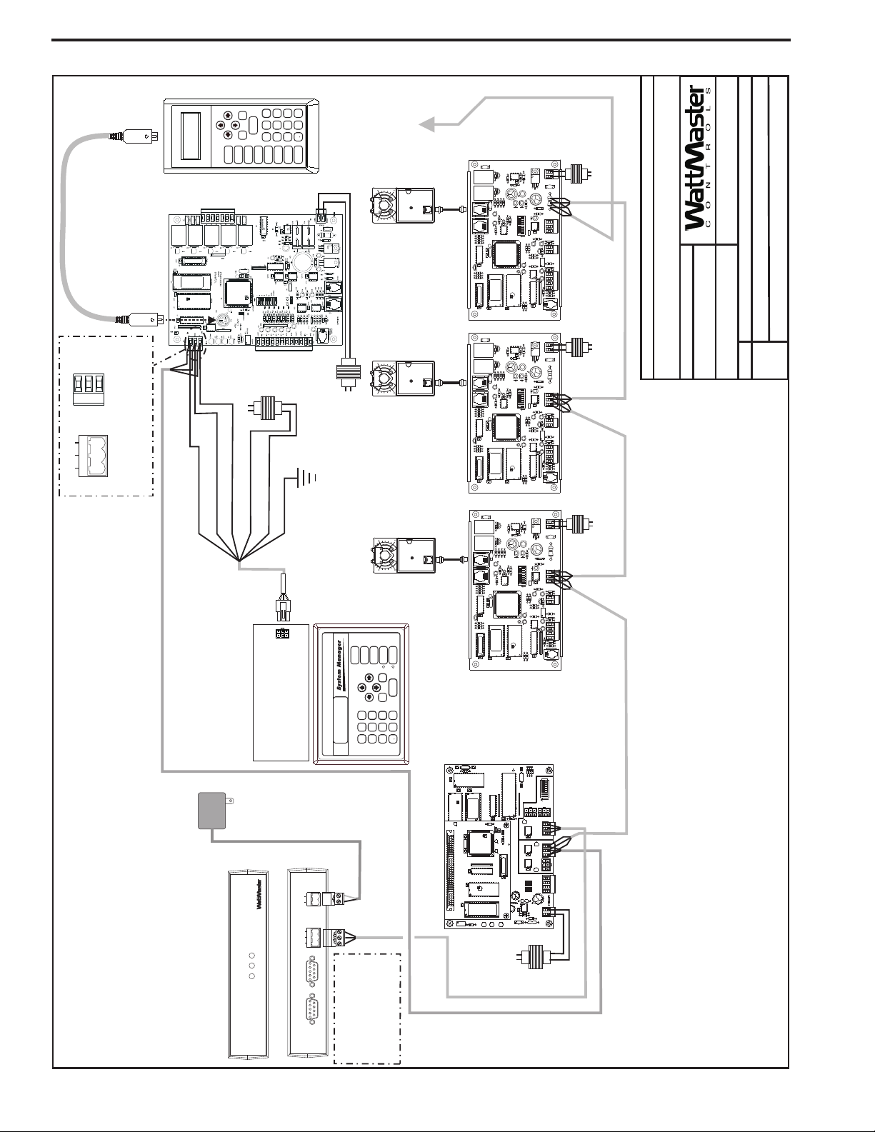
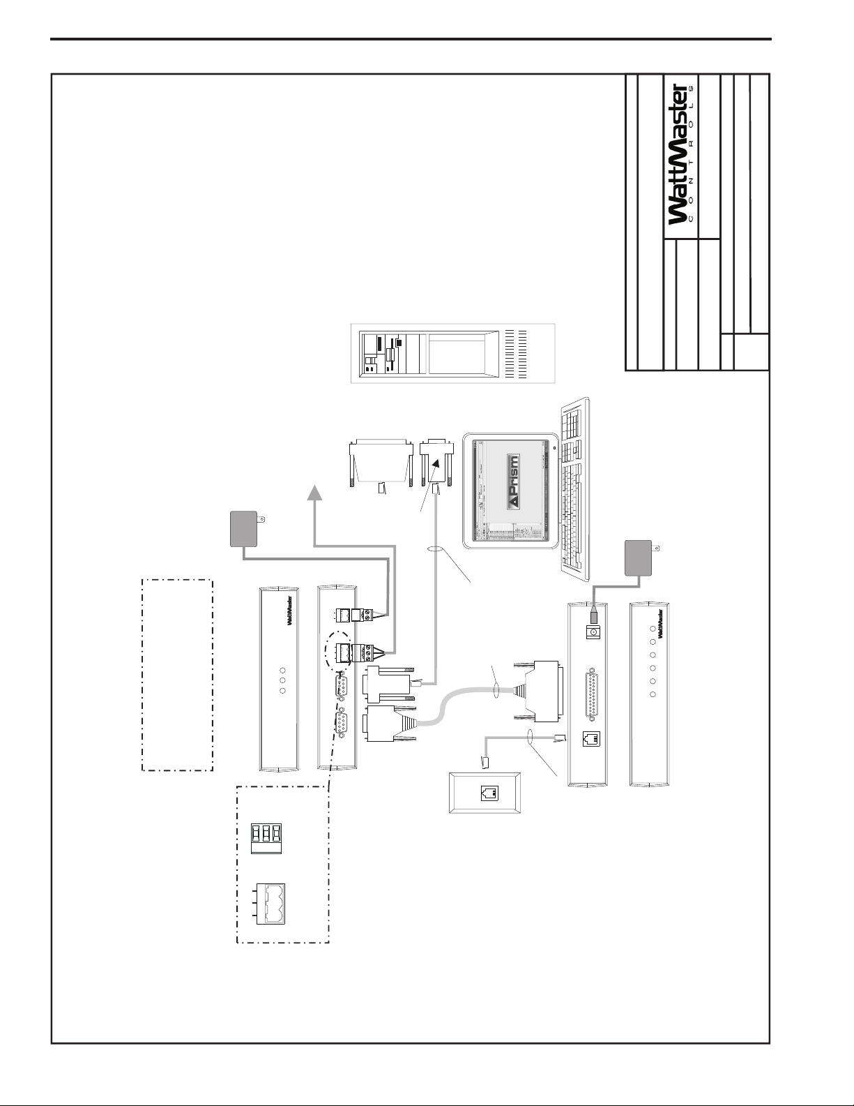
Networked Single Loop System
EPROM
U3
U5
RAM
C
X
2
1
U2
R
1
C3
U4
CX3
CX4
YS101818P552
PROCESSORPBOARD
CX5
C1
U1
R2
CX1
CX6
WDOG
U6
PHILIPS
D
1
P1
X1
C2
C4
0-10V
4-20mA
THERM
R
27
R
31
D
4
G
N
D
24VA
C
TB1
D5
C11
U12
LED2
POWER
V
1
R
25
R
26
C7
C
X15
C
X
13
PROC.
DRIVER
LOOP
DRIVER
LOCALLOOP
G
N
D
A
IN
2
A
IN
1
+5V
T
B2
P4
OFF=0-5V
AIN2
AIN1
0-10V
4-20mA
THERM
TB
3
U
15
LD5
LD6
U
13
C8
LED1
RV1
R
4
V
R
EF
C
X
2
U11
YS101900PMINILINK
POLLING
DEVICE
REV.1
OFF
1
2
4
8
16
32
C
X
14
NETWORK
DRIVER
RN3
SH
LD
S
H
LD
T
T
TB
4
R
R
U14
NETWORK
LOOP
P5
A
D
D
P
3
R
24
LD4
C9
U10
RN2
SW1
R30X2R29
R28
C10
U6
C
X6
C
X1
U7
U1
X
1
C3
C
1
R
3
CX7
Line Voltage
Line Voltage
Network
Local
Local
24 VAC
(8 VA)
24 VAC
(6 VA)
24 VAC
(6 VA)
Back View of CommLink
Front View of CommLink
CLIIomm ink
LOOP
24V
T
G
R
GND
REMOTE LINK
(DTE)
COMPUTER
(DCE)
485
LOOP
STATUS
POW
ER
COM
P
RLINK
SERIAL #
CONTROLS
110 VAC To
24 VAC
Power Pack
CommLink
MiniLink PD Loop 1
VAVBOX
Controller
VAVBOX
Controller
VAVBOX
Controller
WMVAV Controller
(1MEG)
TB1
Connect To Modular
I/O Connectors
Located On Back
Of The System Manager
ENTER
CLEAR
ESC
PREV
NEXT
DOWN
UP
6
5
4
DEC
7
0
8
13
2
9
MINUS
-
STATUS
SETPOINTS
SCHEDULES
ALARMS
OVERRIDES
Modular System Manager
Note: A Modular System
Manager, A Modular Service
Tool Or A PC With Prism
Software Installed Can Be
Used To Program And
Configure TheWattMaster
VAV System.
Note: See Page 2 Of
This Drawing For
Optional Computer
And Remote Link
Connection Diagram.
1 1
1
0 0
0
Modular Service
Tool
Mode
Selection
ENTER
CLEAR
ESC
PREV
NEXT
DOWN
UP
6
5
4
DEC
7
0
8
13
2
9
MINUS
-
STATUS
SETPOINTS
SCHEDULES
CONFIGURATION
ALARMS
ON
OVERRIDES
BALANCE-TEST
Connect To Next
VAVBOX Controller
Local Loop
SHLD
T
R
Typical Terminal Blocks. All
Wiring To Be T To T, SHLD (G)
To SHLD (G)&RToR
T
G
R
485 LOOP
Typical Single Loop Networked System
05/12/04
VAV-Network-SingleLoop1B.CDR
Network System - Single Loop
FILENAME
DATE:
B. Crews
DESCRIPTION:
PAGE
DRAWN BY:
Wiring & Connection Diagram
JOB NAME
1of3
WHITE (T)
DRAIN WIRE (SHLD)
BLACK (R)
RED (24 VAC)
Line Voltage
24 VAC
(6VA Min.)
BROWN (GND)
GREEN (GND)
CX6
SW1
U10
75176
EXPANSION
Q3Q2
D3
VR1
7824
GND
R
SHLD
GND
GND
AUX2
AUX1
AUX
+VS
TMP
T
24VAC
R17
R16
U7
C7
R15
POWER
R21
R35
YS101
562REV 3
D4
R26
LD3
L1
SCAN
REC
R12C6R11
TOKEN
NET
LD2
32
R14
R13
R100
LD1
C5
D1
K1
V2
V3
K2
D2
ACTUATOR
R10
R9
PJ2
V1
C4
EPROM
VREF
ADJ
R23
C10
EWDOG
COMM
D7
CX10
R25
R28
T'STAT
U11
C15
R20
C11
R24
8
16
2
4
ADDRESS
ADD
1
U6
U5
R19
U9
CX9
R32
D5
C14
P.U.
R22
C13
R27
D5
RAM
C9
C8
80C55
2
CX5
PJ1
C3
R8
R7
R5
R6
R4
C2C1
X1
U2
R1
R2
R3
CX2
Q1
16L8
R34
FLOW
U8
1
RN1
CX8
U4
R18
CX4
U3
CX3
U1
PAL
CX1
CX6
SW1
U10
75176
EXPANSION
Q3Q2
D3
VR1
7824
GND
R
SHLD
GND
GND
AUX2
AUX1
AUX
+VS
TMP
T
24VAC
R17
R16
U7
C7
R15
POWER
R21
R35
YS101
562REV 3
D4
R26
LD3
L1
SCAN
REC
R12C6R11
TOKEN
NET
LD2
32
R14
R13
R100
LD1
C5
D1
K1
V2
V3
K2
D2
ACTUATOR
R10
R9
PJ2
V1
C4
EPROM
VREF
ADJ
R23
C10
EWDOG
COMM
D7
CX10
R25
R28
T'STAT
U11
C15
R20
C11
R24
8
16
2
4
ADDRESS
ADD
1
U6
U5
R19
U9
CX9
R32
D5
C14
P.U.
R22
C13
R27
D5
RAM
C9
C8
80C55
2
CX5
PJ1
C3
R8
R7
R5
R6
R4
C2C1
X1
U2
R1
R2
R3
CX2
Q1
16L8
R34
FLOW
U8
1
RN1
CX8
U4
R18
CX4
U3
CX3
U1
PAL
CX1
Line Voltage
Line Voltage
24 VAC
(6VA Min.)
24 VAC
(6VA Min.)
Component & System Wiring6
Page 7
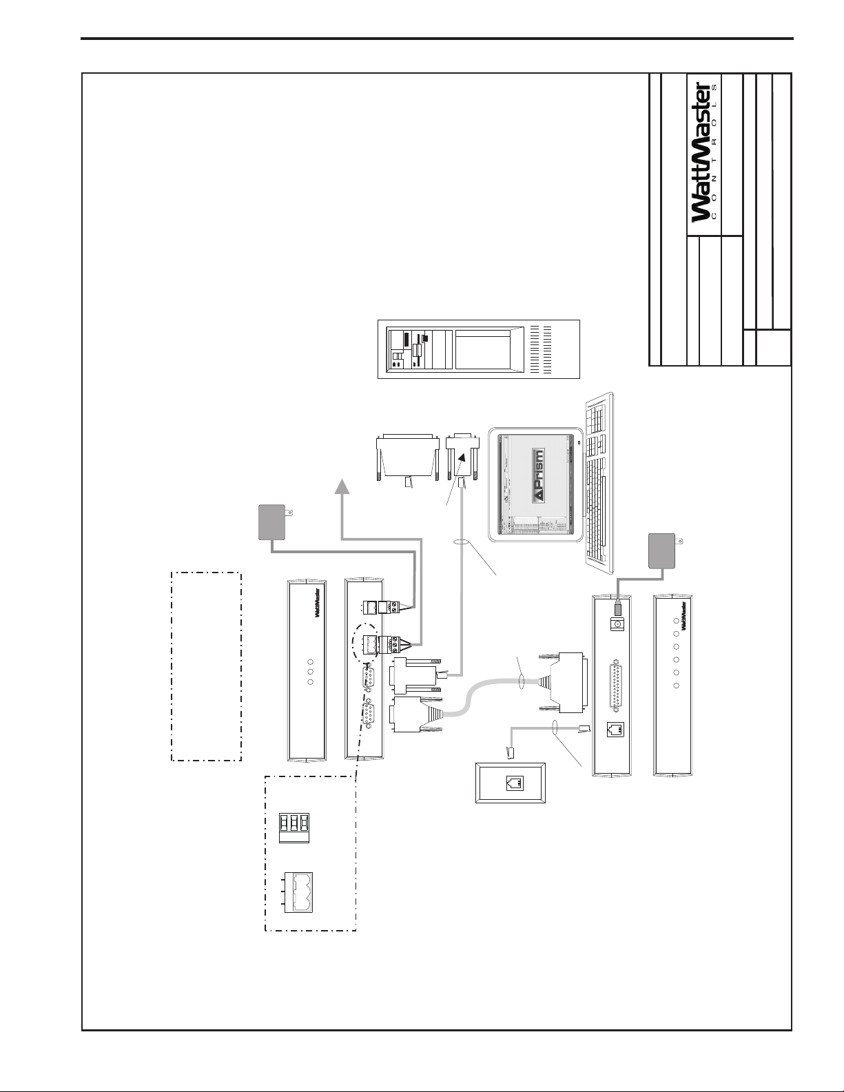
Networked Single Loop - Computer Connection With Remote Link
VAV-Network-SingleLoop1B.CDR
9Pin
Female
End
Telephone
Cable
Assembly
9Pin
Female
Connector
9Pin
Female
Connector
Molded
Cable Assembly
25 Pin
Male End
25 Pin
Female
Connector
(If Reqd)
Connect To Computer
Serial Port
Personal Computer
(By Others)
Dedicated Telephone
Outlet
(By Others)
Back View of CommLink
Back View of Remote Link
Front View of CommLink
Note: If Direct Computer Connection
Is Required, Connect To PC As Shown.
Remote Link Is Only Required If
Alarm Callout Or Remote Computer
Connection Is Required.
Front View of Remote Link
CLIIomm ink
LOOP
24V
T
G
R
GND
REMOTE LINK
(DTE)
COMPUTER
(DCE)
485
LOOP
STATUS
POW
ER
COMP
RLINK
SERIAL #
CONTROLS
RL
emote ink
SIG
TELCO
LINE
TELCO
LINE
SERIAL DATA
DET
RDY
SND
REC
PWR
SERIAL #
CONTROLS
8 Conductor
Modular Cable
Assembly
110 VAC To
9 VDC
Power Pack
110 VAC To
24 VAC
Power Pack
CommLink
Remote Link
(Optional)
Connect To MiniLink PD Network Terminals
See Page 1 Of This Drawing
POWER
9VDC @
500mA
SHLD
T
R
Typical Terminal Blocks. All
Wiring To Be T To T, SHLD (G)
To SHLD (G)&RToR
T
G
R
485
LOOP
FILENAME
DATE:
B. Crews
DESCRIPTION:
PAGE
DRAWN BY:
Wiring & Connection Diagram
JOB NAME
2of3
Network System - Single Loop
03/24/04
Optional Computer Connection Diagram
Using Remote Link For Remote Connection
Component & System Wiring 7
Page 8
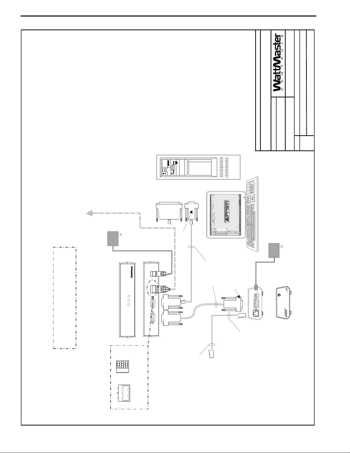
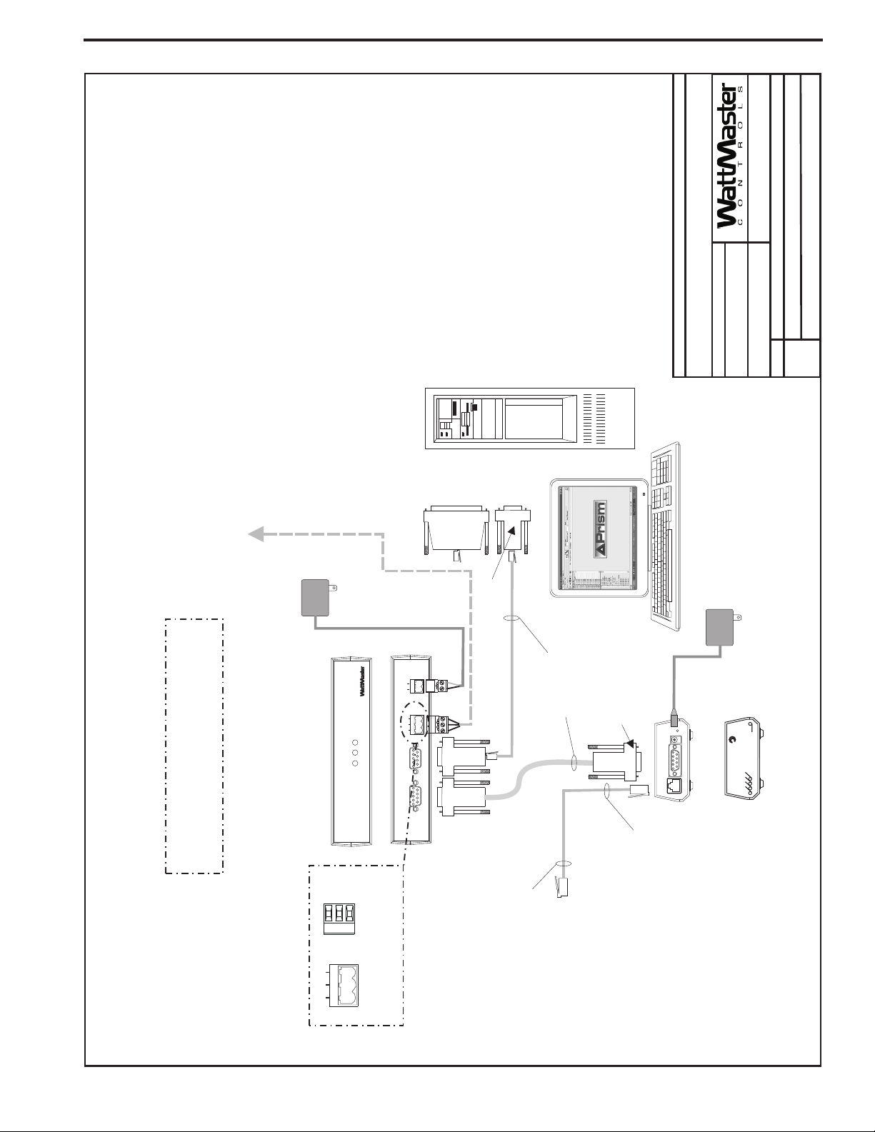
Networked Single Loop - Computer Connection With IP-Link
JOB NAME
FILENAME
B. Crews
DRAWN BY:
DESCRIPTION:
Wiring & Connection Diagram
Network System - Single Loop
03/24/04
DATE:
VAV-Network-SingleLoop1B.CDR
PAGE
3of3
Note: If Direct Computer Connection
Using IP-Link For Remote Connection
Optional Computer Connection Diagram
Is Required, Connect To PC As Shown. IP-Link Is
Only Required If E-mail Alarm Notification Or
Remote Computer Connection Is Required.
Connect To MiniLink PD Network Terminals
See Page 1 Of This Drawing
Note:
1.Set CommLink Internal Switch To”Multi”
2. Replace CommLink EPROM With IP-Link
EPROM Supplied With IP-Link Kit
110 VAC To
RLINK
COM
P
LOOP
CommLink
Front View of CommLink
omm ink
CLII
SHLD
T
R
LOOP
485
R
G
T
24 VAC
Power Pack
CONTROLS
STATUS
Typical Terminal Blocks. All
ER
GND
24V
LOOP
R
G
T
(DCE)
COMPUTER
(DTE)
Back View of CommLink
REMOTE LINK
SERIAL #
Wiring To Be T To T, SHLD (G)
To SHLD (G)&RToR
25 Pin
Female
9 Pin
(If Reqd)
Connector
Female
Connector
(By Others)
Personal Computer
ne
onnect
C
9 VDC
110 VAC To
Power Pack
PWR
R
E
S
V
C
R
K
N
L
T
C
A
IP-Link
(Optional)
Front View of IP- Link
Serial Port
POW
485
Connect To Computer
9 Pin
Female
Connector
Assembly
8 Conductor
Modular Cable
Molded
Supplied With
Cable Assembly
IP-Link Kit
9 Pin Male End
Port On IP-Link
Connect To Serial
Mode
9VDC
Serial
10BaseT
Back View of IP-Link
End
9 Pin
Female
Assembly
On IP-Link
RJ45 Cable
To 10BaseT Port
Connect Ethernet
Or Modem
(By Others)
Cable Assembly
Connect Ethernet RJ45
(By Others)
On Ethernet Router
To 10 BaseT Connection
Component & System Wiring8
Page 9
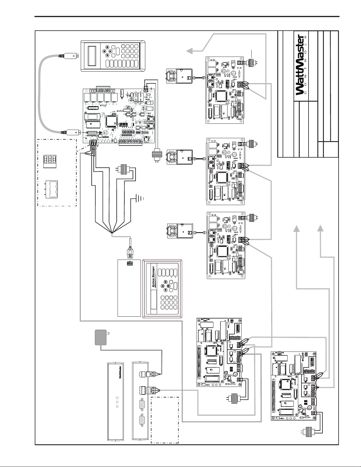
Networked Multiple Loop System
SHLD
T
R
G
T
R
485 LOOP
Typical Terminal Blocks. All
Wiring To Be T To T, SHLD (G)
ToSHLD(G)&RToR
Typical Multiple Loop Networked System
WMVAV Controller
WHITE (T)
Note: A Modular System Manager,
A Modular Service Tool Or A PC
With Prism Software Installed Can
NEXT
CLEAR
UP
DOWN
ENTER
ESC
PREV
STATUS
Mode
SETPOINTS
OVERRIDES
SCHEDULES
Selection
(1MEG)
Line Voltage
DRAIN WIRE (SHLD)
RED (24 VAC)
BLACK (R)
Be Used To Program And
Configure The WattMaster VAV
System.
24 VAC
110 VAC To
RLINK
COM
P
STATUS
LOOP
CommLink
Front View of CommLink
6
9
8
2
5
13
7
4
ALARMS
BALANCE-TEST
CONFIGURATION
24 VAC
(6 VA)
GREEN (GND)
BROWN (GND)
Connect To Modular
I/O Connectors
Located On Back
Power Pack
CONTROLS
Back View of CommLink
-
MINUS
0
DEC
ON
24 VAC
TB1
Of The System Manager
POW
ER
GND
24V
LOOP
485
R
G
T
(DCE)
COMPUTER
(DTE)
REMOTE LINK
Tool
Modular Service
(8 VA)
Line Voltage
Connect To
STATUS
SETPOINTS
OVERRIDES
SCHEDULES
NEXT
CLEAR
UP
DOWN
ESC
PREV
6
2
5
13
4
Next VAVBOX
Controller On
1
0
1
0
1
0
ALARMS
ENTER
9
-
MINUS
0
8
7
DEC
Loop 1
Modular System Manager
U1
MiniLink PD Loop 1
VAVBOX
VAVBOX
VAVBOX
1
CX7
U7
C
X
1
P1
RV1
V2
K2
D2
Q3Q2
D1
K1
R10
R9
V1
ACTUATOR
PJ2
C4
C3
R8
EXPANSION
PJ1
R7
R6
R5
CX5
R4
C2C1
U2
X1
Q1
CX2
R3
EPROM
R2
R1
16L8
PAL
U1
U3
CX1
CX3
Controller
V2
K2
D2
D1
K1
R10
R9
V1
ACTUATOR
PJ2
C4
C3
R8
EXPANSION
PJ1
R7
R6
R5
CX5
R4
C2C1
U2
X1
Q1
CX2
R3
R2
R1
16L8
PAL
Controller
U1
U3
CX1
CX3
V2
K2
D2
D1
K1
R9
V1
ACTUATOR
PJ2
C4
C3
R8
EXPANSION
PJ1
R7
R6
R5
CX5
R4
C2C1
U2
X1
Q1
CX2
R3
R2
R1
16L8
Controller
PAL
U1
U3
CX1
CX3
C
3
C
X
1
R3
YS101900PMINILINK
POLLING
DEVICE
REV.1
C
X
6
U6
U10
D
1
C4
U6
CX6
U1
C2
PHILIPS
X1
CX1
C3
YS101818P552
PROCESSORPBOARD
C1
1
R
1
U2
CX5
U5
CX4
U4
CX3
U3
C
X2
R
4
V
R
E
F
LED1
LED2
24 VAC
24 VAC
(6VA Min.)
GND
R17
R16
U7
R15
R12C6R11
R13
R100
C5
CX6
CX4
24VAC
7824
C7
D3
VR1
V3
L1
562REV 3
SCAN
REC
R35
YS101
R21
LD2
LD1
D4
R14
R26
NET
TOKEN
POWER
LD3
32
R
16
SHLD
8
U10
SW1
4
75176
COMM
2
U6
U5
2
80C55
T
1
CX10
ADD
ADDRESS
D7
R25
EWDOG
C15
GND
R20
C11
R19
TMP
U11
R24
R28
T'STAT
R23
R32
C10
P.U.
VREF
ADJ
D5
R22
C14
C8
RAM
GND
C13
C9
U9
AUX2
CX9
AUX1
+VS
R27
AUX
D5
1
RN1
U8
U4
CX8
FLOW
R34
R18
Line Voltage
JOB NAME
B. Crews
DRAWN BY:
DESCRIPTION:
Network System - Multiple Loop
Wiring & Connection Diagram
05/12/04
24 VAC
Q3Q2
R15
R12C6R11
R13
R100
C5
CX6
EPROM
CX4
Q3Q2
R15
R12C6R11
R10
R13
R100
C5
CX6
EPROM
CX4
24VAC
7824
C7
D3
VR1
V3
L1
562REV 3
SCAN
REC
R35
YS101
R21
LD2
LD1
D4
R14
R26
NET
TOKEN
POWER
LD3
32
R
16
SHLD
8
U10
SW1
4
75176
COMM
2
U6
U5
2
80C55
U7
D3
R14
U6
U5
2
80C55
T
1
CX10
ADD
ADDRESS
D7
R25
EWDOG
C15
GND
R20
C11
R19
TMP
U11
R24
R28
T'STAT
R23
R32
C10
P.U.
VREF
ADJ
D5
R22
C14
C8
RAM
GND
C13
C9
U9
AUX2
CX9
AUX1
+VS
R27
AUX
D5
1
RN1
U8
U4
CX8
FLOW
R34
R18
GND
R17
R16
24VAC
7824
C7
VR1
V3
L1
562REV 3
SCAN
REC
R35
YS101
R21
LD2
LD1
D4
R26
NET
TOKEN
POWER
LD3
32
R
16
SHLD
8
U10
SW1
4
75176
COMM
2
T
1
CX10
ADD
ADDRESS
D7
R25
EWDOG
C15
GND
R20
C11
R19
TMP
U11
R24
R28
T'STAT
R23
R32
C10
P.U.
VREF
ADJ
D5
R22
C14
C8
RAM
GND
C13
C9
U9
AUX2
CX9
AUX1
+VS
R27
AUX
D5
1
RN1
U8
U4
CX8
FLOW
R34
R18
Line Voltage
24 VAC
(6VA Min.)
Line Voltage
(6VA Min.)
GND
R17
R16
U7
FILENAME
DATE:
VAV-Network-MultLoop1B.CDR
Loop 3
Connect To
MiniLink Polling Device
Connect To Loop 2
1of3
PAGE
VAVBOX Controller
Or WMVAV Controller
Local
Local
C10
R30X2R29
R28
OFF
SW1
32
U11
C9
16
8
4
2
RN2
1
RN3
D
D
A
3
P
P5
R
24
LD4
R
U
14
LD
H
S
WDOG
T
NETWORK
DRIVER
C
X14
4
TB
NETWORK
LOOP
R2
3
TB
U
13
LD5
R
LD
SH
LOOP
DRIVER
T
C
X
13
U
15
PROC.
DRIVER
LOCALLOOP
C
X
15
LD6
P4
D
N
G
0-10V
THERM
4-20mA
C
X2
2
IN
A
AIN2
1
AIN
RAM
OFF=0-5V
C8
+5V
AIN1
TB
2
0-10V
THERM
4-20mA
R
27
C7
EPROM
U12
C
R
25
R
26
R
31
V1
POWER
Network
C11
D5
D
N
G
24VA
T
B1
D
4
Local
(6 VA)
C
3
C
1
X1
R
3
CX7
U7
C
X
6
C
X
1
U1
U6
U10
C4
P1
C2
PHILIPS
X1
YS101818P552
PROCESSORPBOARD
C1
CX5
U5
CX4
U4
CX3
MiniLink PD Loop 2
U3
C
X2
RV1
R
4
VR
EF
LED1
YS101900PMINILINK
POLLING
D
1
LED2
Network
C10
R30X2R29
R28
U11
C9
DEVICE
REV.1
RN2
RN3
3
P
R
24
LD4
U6
U
14
CX6
U1
1
LD
WDOG
NETWORK
DRIVER
C
X
14
NETWORK
LOOP
R2
CX1
U
13
LD5
LD
LOOP
DRIVER
C3
C
X
13
U
15
PROC.
R
1
DRIVER
U2
LOCALLOOP
C
X15
LD6
0-10V
THERM
4-20mA
C
X2
2
AIN2
1
RAM
OFF=0-5V
C8
AIN1
0-10V
THERM
4-20mA
R
27
C7
EPROM
D
U12
C
R
25
R
26
R
31
V1
POWER
Network
OFF
SW1
32
16
8
4
2
1
D
AD
P5
R
H
S
T
4
TB
3
TB
R
SH
T
P4
D
N
G
AIN
IN
A
+5V
TB
2
C11
D5
N
G
24VA
TB1
D
4
omm ink
CLII
SERIAL #
Note: See Page 2 and
IP-LinkConnections
3 Of This Drawing For
Optional Computer To
Remote Link or
24 VAC
(6 VA)
Component & System Wiring 9
Page 10
Networked Multiple Loop - Computer Connection With Remote Link
03/24/04
VAV-Network-MultLoop1B.CDR
FILENAME
DATE:
B. Crews
DESCRIPTION:
PAGE
DRAWN BY:
Wiring & Connection Diagram
JOB NAME
2of3
Network System - Multiple Loop
9Pin
Female
End
Telephone
Cable
Assembly
9Pin
Female
Connector
9Pin
Female
Connector
Molded
Cable Assembly
25 Pin
Male End
25 Pin
Female
Connector
(If Reqd)
Connect To Computer
Serial Port
Personal Computer
(By Others)
Dedicated Telephone
Outlet
(By Others)
Back View of CommLink
Back View of Remote Link
Front View of CommLink
Note: If Direct Computer Connection
Is Required, Connect To PC As Shown.
Remote Link Is Only Required If
Alarm Callout Or Remote Computer
Connection Is Required.
Front View of Remote Link
CLII
omm ink
LOOP
24V
T
G
R
GND
REMOTE LINK
(DTE)
COMPUTER
(DCE)
485 LOOP
STATUS
POWER
COMP
RLINK
SERIAL #
CONTROLS
RL
emote ink
SIG
TELCO
LINE
TELCO
LINE
SERIAL DATA
DET
RDY
SND
REC
PWR
SERIAL #
CONTROLS
8 Conductor
Modular Cable
Assembly
110 VAC To
9 VDC
Power Pack
110 VAC To
24 VAC
Power Pack
CommLink
Remote Link
(Optional)
Connect To MiniLink PD Network Terminals
See Page 1 Of This Drawing
POWER
9VDC @
500mA
SHLD
T
R
Typical Terminal Blocks. All
Wiring To Be T To T, SHLD (G)
To SHLD (G)&RToR
T
G
R
485 LOOP
Optional Computer Connection Diagram
Using Remote Link For Remote Connection
Component & System Wiring10
Page 11
Networked Multiple Loop - Computer Connection With IP-Link
JOB NAME
FILENAME
VAV-Network-MultLoop1B.CDR
B. Crews
DRAWN BY:
DESCRIPTION:
Network System - Multiple Loop
03/24/04
DATE:
3of3
PAGE
Wiring & Connection Diagram
Note: If Direct Computer Connection
Using IP-Link For Remote Connection
Optional Computer Connection Diagram
Is Required, Connect To PC As Shown. IP-Link Is
Only Required If E-mail Alarm Notification Or
Connect To MiniLink PD Network Terminals
See Page 1 Of This Drawing
Remote Computer Connection Is Required.
Note:
1.Set CommLink Internal Switch To”Multi”
2. Replace CommLink EPROM With IP-Link
EPROM Supplied With IP-Link Kit
110 VAC To
RLINK
COMP
LOOP
CommLink
Front View of CommLink
CLIIomm ink
SHLD
T
R
LOOP
485
R
G
T
24 VAC
Power Pack
CONTROLS
STATUS
Typical Terminal Blocks. All
ER
GND
24V
R
G
T
(DCE)
COMPUTER
(DTE)
Back View of CommLink
REMOTE LINK
SERIAL #
Wiring To Be T To T, SHLD (G)
To SHLD (G)&RToR
25 Pin
Female
9Pin
(If Reqd)
Connector
Female
Connector
(By Others)
Personal Computer
ne
onnect
C
9 VDC
110 VAC To
Power Pack
PWR
R
E
S
V
C
R
K
N
L
T
C
A
IP-Link
(Optional)
Front View of IP- Link
Serial Port
POW
485 LOOP
Connect To Computer
9Pin
Female
Connector
Assembly
8 Conductor
Modular Cable
Molded
Supplied With
Cable Assembly
IP-Link Kit
9 Pin Male End
Port On IP-Link
Connect To Serial
Mode
9VDC
Serial
10BaseT
Back View of IP-Link
End
9Pin
Female
Assembly
On IP-Link
RJ45 Cable
To 10BaseT Port
Connect Ethernet
Or Modem
(By Others)
Cable Assembly
Connect Ethernet RJ45
(By Others)
On Ethernet Router
To 10 BaseT Connection
Component & System Wiring 11
Page 12

Systems Overview
General Information
The WattMaster VAV system components can be configured into different types of systems depending on the type and number of controllers required. It is a good idea to become familiar with the types of
systems and their architecture by reading the information in this section
and looking at the configuration diagrams in the System Configurations Installation & Commissioning section of this manual. The information below is designed to help you understand how the system components integrate with each other and the available configuration options.
System Types
Two different system configurations are available depending on the type
and number of controllers that you have on your system.
1. Networked Single Loop
(See Pages 6 Through 8 For Connection Diagrams)
2. Networked Multiple Loop
(See Pages 9 Through 11 For Connection Diagrams)
System Type Definitions
Networked Single Loop
The Networked Single Loop system, as its name implies, consists of a
single communications loop. The system can consist of the following
controllers and devices.
1. A single WMVAV controller used as a VAV controller and
it’s associated VAVBOXcontrollers. Other WMVAV
controllers used for constant volume units and/or and Addon Devices may also be connected as long as the total of all
controllers on the loop does not exceed 59. Only one VAV
controller with it’s VAVBOX controllers can be installed
per loop. If more than one VAV controller with VAVBOX
controllers is required, you must have a separate loop for
each.
This system requires one CommLink communications interface and
one MiniLink Polling Device. Programming and status monitoring are
accomplished by the following methods.
1. By using an operators interface. This can be either a
Modular System Manager, a Modular Service Tool or both
devices. The System Manager or Modular Service Tool
can connect to any controller on the local loop.
2. A computer interface can also be used in conjunction with
the other operators interfaces listed above, or by itself. This
requires a personal computer with the Prism computer front
end software installed. The PC connects to the CommLink
via a supplied cable.
2. A single WMVAV controller used as a VAV controller and
its associated VAVBOX controllers. Other WMVAV
controllers used for constant volume units and/or and Addon Devices may also be connected as long as the total of all
controllers on the loop does not exceed 59. Only one VAV
controller with its VAVBOX controllers can be installed
per local loop.
To form the Networked Multiple Loop System the following network
devices are required.
1. A MiniLink Polling Device is required per loop (Local
Loop). This allows the controllers to share information that
is broadcast from one controller to all controllers on that
local loop and also provides alarming and trend logging
capabilities.
2. One CommLink is required for the entire system. It resides
on the Network Loop and allows for communications
between all the local loops and provides for global
broadcasts to all controllers on the entire system.
Programming and status monitoring are accomplished by one or more
of the following methods.
1. By using an operator interface. This can be either a
Modular System Manager, a Modular Service Tool or both
devices. The System Manager or Modular Service Tool can
connect to any controller on any “Local Loop” on the
entire system.
2. A computer interface can also be used in conjunction with
the other operators interfaces listed above, or by itself. This
requires a personal computer with the Prism computer front
end software installed. The PC connects to the CommLink
via a supplied cable.
Network Communications Devices
MiniLink Polling Device
1. This device is required for all Networked Single loop
systems.
2. One of these device is required on each local loop of all
Networked Multiple Loop systems
CommLink
1. One CommLink is required on all Networked Single Loop
or Multiple Loop Systems
2. Up to 60 local loops can be connected to the CommLink
Installation Procedures
Networked Multiple Loop
This Networked Multiple Loop System consists of two or more loops,
each being called ‘Local Loops’, with one ‘Network Loop’ that ties the
“Local Loops” together. Each of these local loops can consist of the
following controllers and devices.
1. A series of WMVAV controllers for constant volume units
and/or Add-on devices without any VAVBOX controllers.
Up to 59 controllers may be connected on the loop in this
manner.
The installation procedures that follow are based on recommended methods of wiring connection and controller installation. Installation procedures vary depending on the which Networked system you are installing. The system you are installing could be “Networked Single Loop”
or a “Networked Multiple Loop” system. The Networked Systems
also have installation variations based on the type of components you
are installing for that system. The following information explains the
procedures for all of these systems. Please find the system and components that closely match your system and follow the outlined procedures.
Component & System Wiring12
Page 13

Networked Single Loop Systems
See the “Networked System - Single Loop Wiring” on pages 6 through
8 of this manual for detailed wiring information. Also see page 16 for
wire and transformer sizing information. You should review these diagrams before attempting connections or powering up the controller or
interface devices.
1. Connect all WMVAV or Add-on Device controllers in a
daisy chain or star ring format by connecting from each
controller’s communication terminal block to the next using
18 gauge, 2 conductor shielded cable. Install a separate 24
VAC, transformer for each controller and wire from each
controller’s power terminal block to its transformer using
18 gauge minimum, 2 wire cable for power. See Wire and
Transformer Sizing section on page 16 for detailed
transformer and wire sizing information. Observe polarity
on all board power wiring. Install a separate 24 VAC, 6 VA
minimum, transformer for each VAVBOX controller on the
loop and wire from each controller’s power terminal block
to its transformer using 18 gauge minimum, 2 wire cable.
Observe polarity on all boards! As an alternative, a single
transformer that connects to all VAVBOX controllers may
also be used. It must be sized to handle the minimum load
of 6 VA per VAVBOX controller connected to it. When
using this method, the polarity of all wiring between the
transformer and the VAVBOX controllers is extremely
critical and must be maintained to prevent damage to
all boards connected! See the wire and transformer sizing
information on page 16 of this manual for complete
wire and transformer sizing information.
Warning: If polarity between controllers is not maintained,
severe damage to the controllers may result.
WattMaster recommends using a separate transformer
for each controller in order to eliminate the potential
for damaging controllers due to incorrect polarity.
2. Using 18 gauge 2 conductor shielded cable, connect from
the WMVAV controller’s 3 wire communications
connector to the MiniLink PD’s 3 wire communications
connector marked “Local Loop”.
3. Connect 2 conductor shielded cable from the
MiniLink PD’s 3 wire communications terminal blocks
labeled “Network Loop” to the CommLink’s 3 wire
communications terminal block located on the back of the
CommLink. Find the 110 VAC/24 VAC power supply
furnished with the CommLink and connect the 2 stripped
wire leads to the 24 VAC terminals on the back of the
CommLink. The CommLink’s internal jumper must be set
to “Multiple” for all WattMaster VAV systems. See page 45
of this manual for complete CommLink wiring and jumper
setting information. After determining all wiring and
jumper settings are correct, connect the power supply plugin transformer to a 110 V receptacle.
4. Install a 24 VAC, 6 VA minimum, transformer for the
MiniLink PD and wire it to the 24 VAC power terminal
block on the MiniLink PD using 18 gauge minimum, 2
wire cable. See page 46 of this manual for complete
MiniLink PD wiring diagrams and instructions.
5. When the Modular Service Tool is to be used for
programming and monitoring of the controllers it can be
connected to the WMVAV controllers using the supplied
cable with DIN connectors on both ends. The DIN
connector on the WMVAV controller is located near the
communications terminals. To connect the Modular Service
Tool to a VAVBOX controller first unplug the 3 wire
communication terminal block from the VAVBOX
controller. Connect the DIN to terminal adapter terminal
end to the communication terminals block socket on the
VAVBOX controller then connect the DIN connector side
of the adapter to the Modular Service Tool cable DIN
connector. See page 44 of this manual for complete
Modular Service Tool connection diagrams and
instructions.
6. The Modular System Manager comes supplied with a 12
foot modular cable pigtail with a modular connector on one
end and stripped wires on the other. Plug the modular
connector end into the System Manager modular connector.
Run 18 gauge, 2 conductor shielded cable for
communications from the MiniLink PD or any controller
on the local loop by connecting one end of the controller’s
or MiniLink PD’s 3 wire “Local Loop” communications
terminal block to a junction box located within 12 feet of
the System Manager. Run 18 gauge, 2 wire, power wires
supplied by a separate 24 VAC, 6 VA minimum transformer
into the junction box. Splice the stripped modular cable
ends from the System Manager to the communications and
power wire inside of the junction box using solid
connections made with wire nuts or butt-splice connectors.
See Modular System Manager wiring on pages 42 and 43
of this manual for wiring color coding and complete wiring
instructions. The Modular System Manager MUST always
be connected on the “Local Loop”, never the “Network
Loop”.
Networked Multiple Loop Systems
See the “Networked System - Multiple Loop Wiring” on pages 9 through
11 of this manual for detailed wiring diagrams. Also see page 16 for
wire and transformer sizing information. You should review these diagrams before attempting connections or powering up the controller or
interface devices.
Loop(s) with WMVAV Controllers without VAVBOX Controllers
1. For each local loop on the system, connect all controllers in
a daisy chain or star ring format by connecting from each
controllers communication terminal block to the next using
18 gauge, 2 conductor shielded cable. Install a separate 24
VAC, 8 VA minimum, transformer for each controller and
wire from each controller’s power terminal block to its
transformer using 18 gauge minimum, 2 wire cable for
power. Observe polarity on all boards.
2. Select one of the local loops and connect 2 conductor
shielded cable from one of its WMVAV controller’s 3 wire
communications terminal blocks to it’s associatedMiniLink
PD’s 3 wire communications terminal block marked “Local
Loop”. Repeat this procedure for all loops on the entire
system.
Component & System Wiring 13
Page 14

System Installation
3. Connect 2 conductor shielded cable from one of the
systems MiniLink PD’s 3 wire communications terminal
blocks labeled “Network Loop” to the CommLink’s 3 wire
communications terminal block located on the back of the
CommLink. Find the 110 VAC/24 VAC power supply
furnished with the CommLink and connect the 2
stripped wire leads to the 24 VAC terminals on the back of
the CommLink. The CommLink’s internal jumper must be
set to “Multiple” for all WattMaster VAV systems. See page
45 of this manual for complete CommLink wiring and
jumper setting information. After determining all wiring
and jumper settings are correct, connect the power supply
plug-in transformer to a 110 V receptacle.
4. Connect 2 conductor shielded cable for network
communications between each MiniLink PD on the system
including the one that was just connected to the
CommLink. This is accomplished by connecting between
each MiniLink PD’s 3 wire communications terminal block
labeled “Network Loop” and the next MiniLink PD’s
communications terminal block labeled “Network Loop”.
Install a 24 VAC, 6 VA minimum, transformer for each of
the MiniLink PDs on the system and wire each transformer
to the 24 VAC power terminal block for its respective
MiniLink PD using 18 gauge minimum, 2 wire cable. See
page 46 of this manual for complete MiniLink PD wiring
diagrams and instructions.
5. When the Modular Service Tool is to be used for
programming and monitoring of the controllers it can be
connected to the WMVAV controllers using the supplied
cable with DIN connectors on both ends. The DIN
connector on the WMVAV controller is located near the
communications terminals. See page 44 of this manual for
complete Modular Service Tool connection diagrams and
instructions.
6. The Modular System Manager comes supplied with a 12
foot modular cable pigtail with a modular connector on one
end and stripped wires on the other. Plug the modular
connector end into the System Manager modular connector.
Run 18 gauge, 2 conductor shielded cable for
communications from the MiniLink PD or any controller
on the local loop by connecting one end the controller’s or
MiniLink PD’s 3 wire “Local Loop” communications
terminal block to a junction box located within 12 feet of
the System Manager. Run 18 gauge, 2 wire, power wires
supplied by a separate 24 VAC, 6 VA minimum transformer
into the junction box. Splice the stripped modular cable
ends from the System Manager to the communications and
power wire inside of the junction box using solid
connections made with wire nuts or butt-splice connectors.
See Modular System Manager wiring on pages 42 and 43
of this manual for wiring color coding and complete wiring
instructions. The Modular System Manager MUST always
be connected on the “Local Loop”, never the “Network
Loop”.
Loop(s) with WMVAV and VAVBOX Controllers
1. Select one of the local loops on your system. Connect all
WMVAV or Add-on Device controllers in a daisy chain or
star ring format by connecting from each controller’s
communication terminal block to the next using 18 gauge,
2 conductor shielded cable. Install a separate 24 VAC,
transformer for each controller and wire from each
controller’s power terminal block to its transformer using
18 gauge minimum, 2 wire cable for power. See Wire and
Transformer Sizing section on page 16 for detailed
transformer and wire sizing information. Observe polarity
on all board power wiring. Install a separate 24 VAC, 8 VA
minimum, transformer for each VAVBOX controller on the
loop and wire from each controller’s power terminal block
to it’s transformer using 18 gauge minimum, 2 wire cable.
Observe polarity on all boards! As an alternative, a single
transformer that connects to all VAVBOX controllers may
also be used. It must be sized to handle the minimum load
of 6 VA per VAVBOX controller connected to it. When
using this method, the polarity of all wiring between the
transformer and the VAVBOX controllers is extremely
critical and must be maintained to prevent damage to
all boards connected! See the wire and transformer sizing
information on page 16 of this manual for complete wire
and transformer sizing information. Repeat this procedure
for each loop with VAVBOX controllers on your system.
Warning: If polarity between controllers is not maintained,
severe damage to the controllers may result.
WattMaster recommends using a separate transformer
for each controller in order to eliminate the potential
for damaging controllers due to incorrect polarity.
2. For each local loop on the system do the following. Using
18 gauge 2 conductor shielded cable, connect from
one of the WMVAV controller’s on the loop, 3 wire
communications connector to that loop’s MiniLink PD 3
wire communications terminal block marked “Local Loop”.
3. To install the CommLink, connect 2 conductor shielded
cable from one of the system’s MiniLink PD’s 3 wire
communications terminal blocks labeled “Network Loop”
to the CommLink’s 3 wire communications terminal block
located on the back of the CommLink. Find the 110 VAC/
24 VAC power supply furnished with the CommLink and
connect the 2 stripped wire leads to the 24 VAC terminals
on the back of the CommLink. The CommLink’s internal
jumper must be set to “Multiple” for all WattMaster VAV
systems. See page 45 of this manual for complete
CommLink wiring and jumper setting information. After
determining all wiring and jumper settings are correct,
connect the power supply plug-in transformer to a 110 V
receptacle.
4. The following procedure must be performed for each
MiniLink PD on your system. Install a 24 VAC, 6 VA
minimum, transformer for theMiniLink PD and wire it to
the 24 VAC power terminal block on the MiniLink PD
using 18 gauge minimum, 2 wire cable. See page 46 of this
manual for complete MiniLink PD wiring diagrams and
instructions. Be sure that all MiniLink PDs on the entire
system are wired as required.
Component & System Wiring14
Page 15

5. When the Modular Service Tool is to be used for
programming and monitoring of the controllers it can be
connected to the WMVAV controllers using the supplied
cable with DIN connectors on both ends. The DIN
connector on the WMVAV controller is located near the
communications terminals. To connect the Modular Service
Tool to a VAVBOX controller, first unplug the 3 wire
communication terminal block from the VAVBOX
controller. Connect the DIN to terminal adapter terminal
end to the communication terminals block socket on the
VAVBOX controller then connect the DIN connector side
of the adapter to the Modular Service Tool cable DIN
connector. See page 44 of this manual for complete
Modular Service Tool connection diagrams and
instructions.
System Commissioning
6. The Modular System Manager comes supplied with a 12foot modular cable pigtail with a modular connector on one
end and stripped wires on the other. Plug the modular
connector end into the System Manager modular connector.
Run 18 gauge, 2 conductor shielded cable for
communications from the MiniLink PD or any controller
on the local loop by connecting one end the controller’s or
MiniLink PD’s 3 wire “Local Loop” communications
terminal block to a junction box located within 12 feet of
the System Manager. Run 18 gauge, 2 wire, power wires
supplied by a separate 24 VAC, 6 VA minimum transformer
into the junction box. Splice the stripped modular cable
ends from the System Manager to the communications and
power wire inside of the junction box using solid
connections made with wire nuts or butt-splice connectors.
See Modular System Managerl wiring on pages 42 and 43
of this manual for wiring color coding and complete wiring
instructions. The Modular System Manager MUST always
be connected on the “Local Loop”, never the “Network
Loop”.
The following information is a brief overview of the procedures required to commission a typical WattMaster VAV System.
1. Address each MiniLink PD on the system with a unique
address from 1 to 60.
2. On a loop of WMVAV controllers and/or Add-on Devices,
without VAVBOX Controllers, address the controllers and
devices from 1 to 59.
3. On a loop which has VAVBOX controllers, address
the VAVBOX controllers from 1 to 58. Address the
WMVAV controller serving the VAVBOX controllers as
address 59. Address all other controllers with addresses not
already used by other controllers on the loop.
4. Always apply power to the system in the following order.
WMVAV controllers or Add-on Devices, MiniLink PD(s),
CommLink, VAVBOX controllers (if used).
5. After powering up verify diagnostics LED indicator for
proper operation of all controllers. See the technical guide
for each specific controller for detailed information on the
location of its diagnostic LED, and each controller’s
start-up sequence.
6. If a computer is used, install the Prism computer front end
software on it and connect it to the CommLink to access
all of the controllers on the entire system for programming.
7. If a computer is not used, and if a Modular System Manger
is not already connected on the local loop, connect a
Modular Service Tool to one of the controllers to perform
programming of all controllers on the entire system.
Component & System Wiring 15
Page 16
Transformer & Wire Sizing
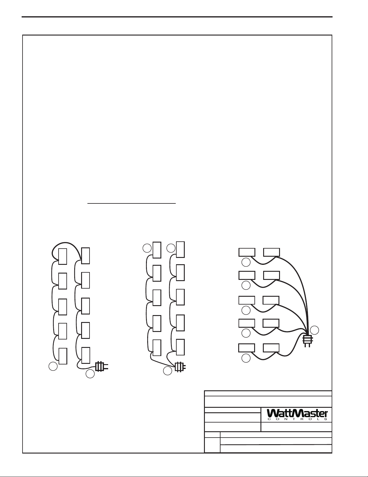
24VAC Power - Transformer & Wire Sizing Considerations For VAVBOX Controllers
Some installers like to use one large 24VAC transformer to power several devices. This is allowable as long as polarity is maintained to each device on
the transformer circuit.
using a separate transformer for each device in order to eliminate the potential for damaging controllers due to incorrect polarity.
separate transformers also allows redundancy in case of a transformer failure. Instead of having 8 controllers inoperative because of a malfunctioning
transformer you have only 1 controller off line. If the installer does decide to use a large transformer to supply power to several devices, the following
transformer and wire sizing information is presented to help the installer correctly supply 24VAC power to the devices.
Following is a typical example to help the installer to correctly evaluate transformer and wiring designs.
Each VAVBOX Controller requires 6 VA @ 24VAC power. In the examples below we have a total of 10 VAV Controllers.
10 VAVBOX Controllers @ 6VA each................ 10 x 6VA =60VA.
The above calculation determines that our transformer will need to be sized for a minimum of 60VA if we are to use one transformer to power all the
controllers. We will use a 75 VA transformer, as this is a readily available size that meets our VA load requirements.
Next we must determine the maximum length of run allowable for the wire gauge we wish to use in the installation. Each wire gauge below has a
voltage drop per foot value we use to calculate total voltage drop.
18ga wire.................................0.00054 = voltage drop per 1’ length of wire
16ga wire.................................0.00034 = voltage drop per 1’ length of wire
14ga wire.................................0.00021 = voltage drop per 1’ length of wire
For our example we will use 18 gauge wire. WattMaster recommends 18 gauge as a minimum wire size for all power wiring.
Next use the voltage drop per foot value for 18 gauge wire from the list above and multiply by the total VA load of the 10 controllers to be installed.
0.00054 (Voltage drop per foot for 18 gauge wire) x 60VA controller load = Volts/Ft.
WattMaster VAVBOX controllers will operate efficiently with a voltage drop no greater than 2 Volts. Divide the total allowable voltage drop of 2 Volts by
the number you arrived at above and you have the maximum number of feet you can run the 18 gauge wire with an 75 VA transformer with no more
thana2Voltdrop at the farthest controller from the transformer..
Parallel circuiting of the wiring instead of wiring all 10 controllers in series allows for longer wire runs to be used with the same size wire (as shown in
our examples below).
transformer size, multiple transformers, circuiting, etc., when laying out an installation. No matter what layout scheme is decided upon, it is mandatory
that the farthest controller on the circuit is supplied with a minimum of 22 Volts and that the polarity is maintained to all controllers connected to the
transformer.
Warning:
It is often necessary for the installer to calculate and weigh the cost and installation advantages and disadvantages of wire size,
If polarity is not maintained, severe damage to the devices may result. WattMaster Controls recommends
0.0324
2 (Volts total allowable voltage drop)
0.0324 (Voltage drop per 1 ft. @ 60VA load)
= 61.73
feet
Using
B
A
120 / 24VAC
Distance A to B cannot exceed 61.73 Ft.
Component Power Requirements
VAV/CAV Controller ..................8VA
VAVBOX Controller..... ..............6VA
Optimal Start Scheduler............10VA
GPC Controller.................. .......8VA
BC
A
120 / 24VAC
Distance from A to B cannot exceed 123.46 Ft.
Distance from A to C cannot exceed 123.46 Ft.
GPC-17 Controller....................10VA
Lighting Panel Controller ..........10VA
MiniLink Polling Device............. 6VA
Distance from A to B cannot exceed 230.40 Ft.
Distance from A to C cannot exceed 308.64 Ft.
Distance from A to D cannot exceed 308.64 Ft.
Distance from A to E cannot exceed 308.64 Ft.
Distance from A to F cannot exceed 308.64 Ft.
FILENAME
VAV-WIRSIZ1.CDR
DATE:
05/12/04
PAGE
1of1
Wire & Transformer Sizing
F
E
D
C
B
JOB NAME
DRAWN BY:
DESCRIPTION:
WattMaster VAV
A
120 / 24VAC
B. CREWS
Component & System Wiring16
Page 17

WMVAV Controller Wiring
Component & System Wiring 17
Page 18

WMVAV Controller Wiring
3
2
1
+
_
All Comm Loop Wiring Is
Straight Thru
TtoT
RtoR
SHLD to SHLD
Connect To Next Controller,
MiniLink PD Or System Manager
See Individual Sensor
Wiring Diagrams For
Detailed Sensor Wiring
VFD 0-10VDC Input
GND
Supply Fan
Variable Frequency Drive
(By Others)
The VFD Unit Must Be
Configured For 0-10VDC
Input. The Input Resistance
At The VFD Must Not Be
Less Than 1000 Ohms When
Measured At The VFD
Terminals With All Input
Wires Removed.
Local Loop RS-485
9600 Baud
On Local Loop
Analog Inputs
C21
RN1
1
TB1
COMM
T
SHLD
R
CX5
LD6
COMM
LD7
1
PWR
LD8
LED1
RN3
LD9
LED2
R1
+VREF
TESTPOINT
U7
RV1
VREFADJ
INPUTS
+VDC
RN5
AIN1
AIN2
AIN3
AIN4
AIN5
C10
GND
GND
AOUT1
AOUT2
AIN7
GND
PJ1
TB3
PRESSURE
SENSOR
EXPANSION
Splice If Req’d
S.P.
Transducer
CX1
U2
U1
U5
RS-485
COMM
5.11V
C12
C17
P1
EWDOG
R26
RAM
HH
C1
R28
ADDRESS
PU1
D6
PU2
D7
PU3
D8
PU4
SW1
D9
PU5
D11
PU7
0-5
VDC
D14
U13
CX13
D15
U15
C20
CX15
PJ2
CX2
U6
PHILIPS
0-1
ADD
2
4
8
16
32
TOKEN
NETWORK
VDC
JP1
U3
CX3
EPROM
TUC-5R PLUS
(1 MEG)
YS101816 REV.2
CX6
C2
X1
C3
1
CX10
U10
CX12
C11
X2
R15
U12
CX14
C14
R19
U14
C15
R22
R24
R25
D18
D17
PJ3
C18
T'STAT
Not Used
Connect To
Expansion Board
Base (When Used)
D1
CX4
U4
RLY1
D2
RLY2
D3
PAL
1
RLY3
D4
RN2
RLY4
D5
RLY5
1
RN4
U9
C7
R7
D10
L1
R10
D13
D12
R13
SC1
D19
C19
VR1
VR2
Jumper Must
Be In 0-5V Position
As Shown
CX8
D16
COM1-3
COM4-5
NE5090NPB3192
0PS
R6
C9
R11
R27
V6
R1
R2
R3
R4
R5
U8
9936
V1
V2
V3
V5
U11
MC34064A
C13
C16
GND
POWER
24VAC
R - 24VAC
G - Fan ON/OFF Only
TB2
Relay Output Dry Contacts
R2 Thru R5 May Be User Configured
V4
For The Following:
1 - Heating (Aux. Heating)Stages
2 - Cooling (Compressor) Stages
3 - Warm-up Mode Command For Boxes
4 - Reversing Valve (Air To Air Heat Pumps)
5 - Gas Reheat Control For Dehumidification
6 - Exhaust Fan Interlock
7 - Preheat Coil
8 - Alarm Relay
9 - Override
10 - Occupied
11 - Economizer
Note: Up To 16 More Relays Are Available By
Adding Relay Expansion Boards. All
Expansion Board Relay Outputs Are User
Configurable As Listed Above.
TB4
GND
24VAC
Size Transformer For
Correct Total Load. WMVAV
Controller = 8 VA Power
Consumption. If Economizer
Option Is Used
The Economizer Actuator
VA load Must Also Be
Considered When Sizing
The Transformer.
Line Voltage
Economizer
Actuator
(Belimo Shown)
Consult Factory For
Other Manufacturers
Wiring Connections
Warning:
24 VAC Must Be Connected So That All Ground
Wires Remain Common. Failure To Do So Will
Result In Damage To The Controllers.
Notes:
1.)24 VAC Must Be Connected So That
All Ground Wires Remain Common.
2.)All Wiring To Be In Accordance With
Local And National Electrical Codes
and Specifications.
3.)All Communication Wiring To Be 18
Ga. Minimum, 2 Conductor Twisted
Pair With Shield. Belden #82760 Or
Equivalent.
4.)When Humidity Sensor Is To Be
Installed A 250 Ohm Resistor Must Be
Installed On The Ground Side Of The
Sensor And Pull Up Resistor PU5
Must Be Removed From The
Controller. See Humidity Sensor
Wiring Diagram In The WMVAV
section of this manual.
Connect Tubing To High Pressure
Port (Bottom Tube) and Route To Static
Pressure Pickup Probe Located In Unit
Discharge. Leave Port Marked “Lo” Open
GND
To Atmosphere
24VAC
5.)If The Slide Adjust Option Is Used On
The Room Sensor , The AUX
Connection Must Be Wired To AIN7.
The Fan Proof Of Flow Switch,
Which Normally Connects To AIN7, Is
Not Available For Use When The
Slide Adjust Option Is Used.
FILENAME
VAV-WMVAVWIR1A.CDR
DATE:
05/12/04
PAGE
1of2
JOB NAME
DRAWN BY:
B. Crews
DESCRIPTION:
WMVAV Controller
Component Wiring Diagram
Component & System Wiring18
Page 19
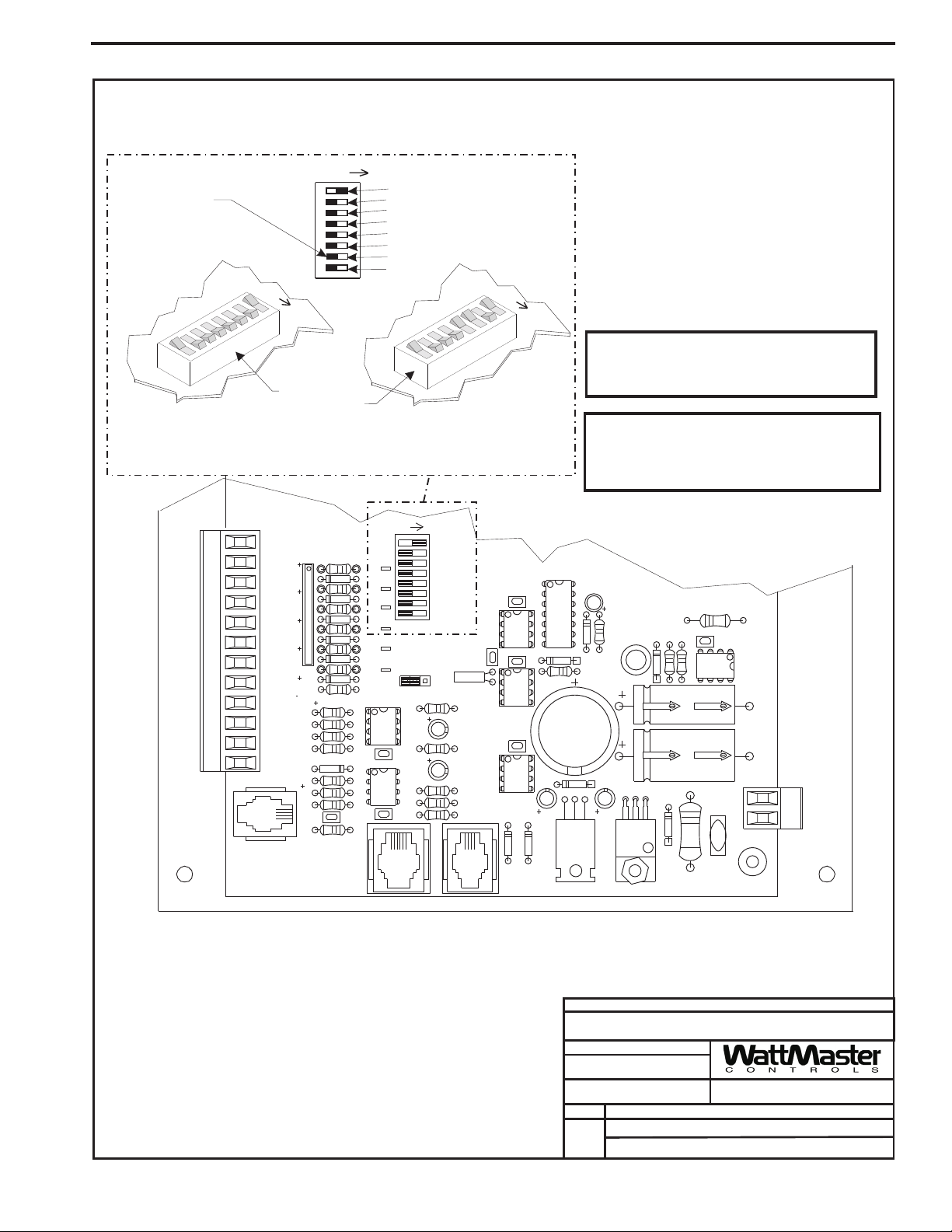
WMVAV Controller Addressing
This Switch Should Be
In The OFF Position
As Shown
ADDRESS ADD
Address Switch Shown Is
Set For Address 1
The Address For Each Controller
Must Be Unique To The Other Controllers
On The Local Loop And Be Between 1 and 59
INPUTS
+VDC
AIN1
AIN2
AIN3
AIN4
AIN5
GND
GND
AOUT1
AOUT2
AIN7
GND
PJ1
TB3
PRESSURE
SENSOR
ADDRESS ADD
Controller
Address Switch
RN5
C10
C17
C12
R26
C20
D15
PU1
D6
PU2
D7
PU3
D8
PU4
D9
PU5
D11
PU7
D14
PJ2
EXPANSION
1
2
4
8
16
32
TOKEN
NETWORK
ADDRESS ADD
Address Switch Shown Is
Set For Address 13
0-5
CX13
CX15
U15
SW1
VDC
0-1
ADD
1
2
4
8
16
32
TOKEN
NETWORK
VDC
JP1
PJ3
C14
C15
U10
C11
X2
R15
R19
R22
R24
R25
ADDRESS
U13
U14
D17
CX10
U12
CX14
D18
CX12
Note:
The Power To The Controller Must Be Removed And
Reconnected After Changing The Address Switch
Settings In Order For Any Changes To Take Effect.
Caution
Disconnect All Communication Loop Wiring From The
Controller Before Removing Power From The Controller.
Reconnect Power And Then Reconnect Communication
Loop Wiring.
C7
D16
R6
C9
R11
U11
C13
C16
TB4
GND
R27
V6
POWER
C18
D10
D12
R13
SC1
D19
C19
R7
L1
R10
D13
24VAC
VR1
VR2
JOB NAME
FILENAME
VAV-WMVAVWIR1A.CDR
PAGE
2of2
DATE:
05/12/04
DRAWN BY:
DESCRIPTION:
WMVAV Controller
Component Wiring Diagram
B. Crews
Component & System Wiring 19
Page 20
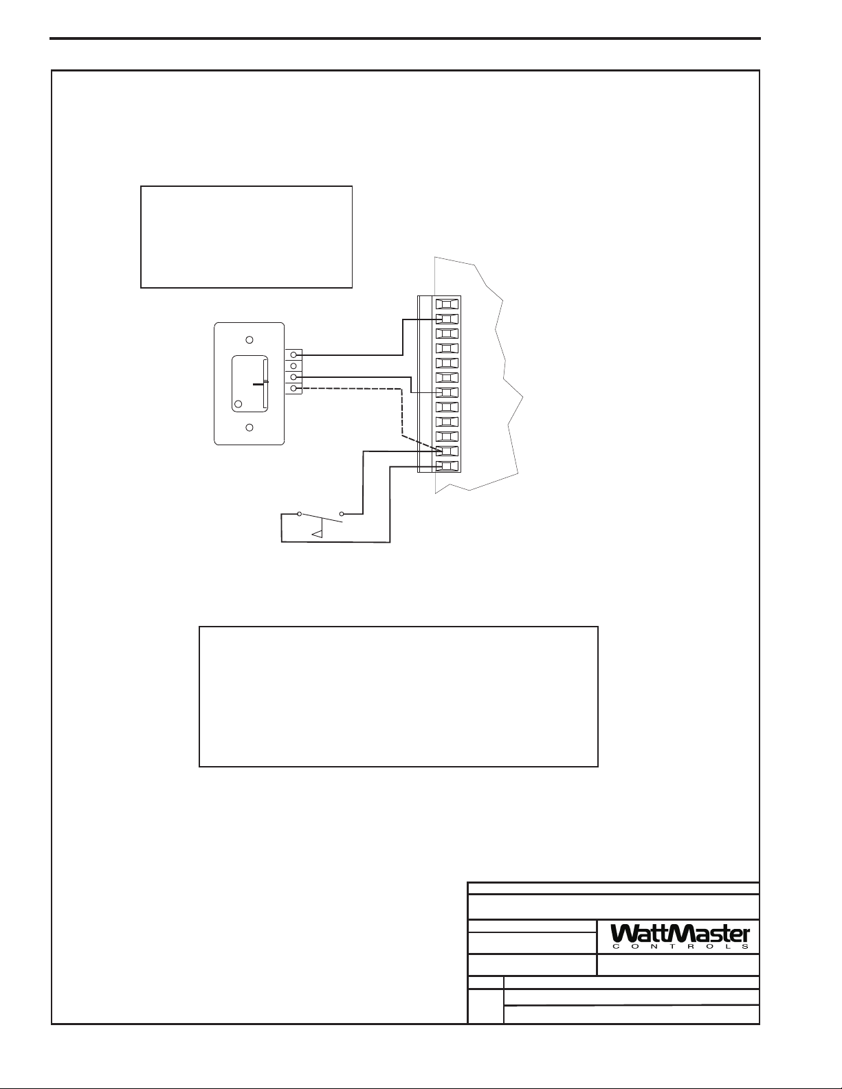
Space Sensor Wiring
Note:
If The Slide Adjust Option Is Used On
The Room Sensor The AUX Terminal
Must Be Wired To AIN7. The Fan Proof
Of Flow Switch, Which Normally
Connects To AIN7, Is Not Available For
Use When The Slide Adjust Option Is
Used.
Space Temperature Sensor
NORMAL
OVR
W
A
R
M
E
R
C
O
O
L
E
R
TMP
GND
AUX (See Note)
Fan Proof Of
Flow Switch
(See Note)
INPUTS
+VDC
AIN1
AIN2
AIN3
AIN4
AIN5
GND
GND
AOUT1
AOUT2
AIN7
GND
WMVAV Controller Board
Space Temperature Sensor Information
The Space Temperature Sensor is typically used for constant volume HVAC
unit applications controlling one zone. The Space Temperature Sensor is a
10K Type III thermistor sensor. The Space Temperature Sensor should be
mounted approximately 5 ft. above the floor in the space that is to be
controlled. The Space Temperature Sensor is available in a sensor only,
sensor with override button, sensor with slide adjust and sensor with slide
adjust and override configurations. If the Space Temperature Sensor with
Slide Adjust option is to be used, the Fan Proof of Flow Switch cannot be
used.
Notes:
1.)All Wiring To Be In Accordance With
Local And National Electrical Codes
and Specifications.
FILENAME
VAV-SpaceTempWire1.CDR
DATE:
05/12/04
PAGE
1
Space Temperature Sensor To
WMVAV Controller Wiring
JOB NAME
DRAWN BY:
DESCRIPTION:
B. Crews
Component & System Wiring20
Page 21
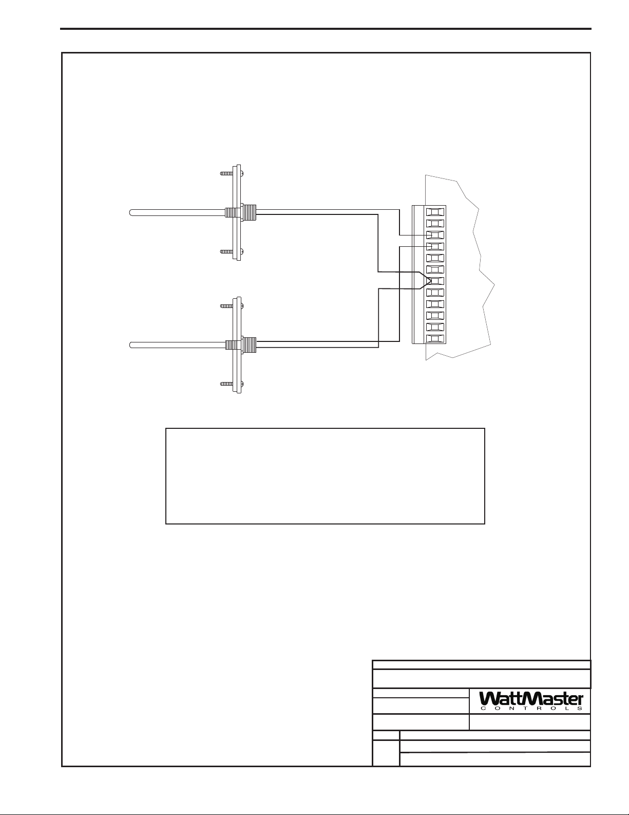
Supply & Return Sensor Wiring
Supply
Air Temperature
Sensor
Mount In HVAC
Unit Supply
Air Duct
Return
Air Temperature
Sensor
INPUTS
+VDC
AIN1
AIN2
AIN3
AIN4
AIN5
GND
GND
AOUT1
AOUT2
AIN7
GND
Mount In HVAC
Unit Return
Air Duct
WMVAV Controller Board
Supply & Return Sensor Information
The Supply and Return Air Temperature Sensors must be wired as shown in the
illustration below for proper operation. The Supply and Return Air Temperature
Sensors are 10K Type III thermistor sensors. The Supply Air Temperature Sensor
should be mounted in the unit discharge plenum or in the supply air duct. The Return
Air Temperature Sensor should be mounted in the return air duct. If the system has a
bypass damper installed, be sure the return air sensor is located upstream of the
bypass duct connection.
Notes:
1.)All Wiring To Be In Accordance With
Local And National Electrical Codes
and Specifications.
FILENAME
VAV-SupRetTempWire1.CDR
DATE:
03/24/04
PAGE
Supply & Return Air Temperature Sensor To
1
JOB NAME
DRAWN BY:
DESCRIPTION:
WMVAV Controller Wiring
B. Crews
Component & System Wiring 21
Page 22

Outside Air Sensor Wiring
Caution:
Be sure to mount the Outside Air Sensor in an area that is not exposed to direct sunlight. A
shaded area under the eve of the building or under the HVAC unit rainhood is normally a good
location. If sensor is not located as specified, erroneous outside air temperature readings will
result. Unused conduit opening(s) must have closure plugs installed and must be coated with a
sealing compound to provide raintight seal. Water can damage sensor!
Outdoor
Air Temperature
Sensor
Make Splice Connections
Inside Sensor Enclosure
As Shown.
INPUTS
+VDC
AIN1
AIN2
AIN3
AIN4
AIN5
GND
GND
AOUT1
AOUT2
AIN7
GND
WMVAV Controller
Outside AirTemperature Sensor
The Outside Air Sensor must be wired as shown in the illustration above for proper
operation. The Outside Air Temperature Sensor is a 10K Type III thermistor sensor.
The sensor should be mounted in the upright position as shown, in an area that is
protected from the elements and direct sunlight. Be sure to make the wiring splices
inside of the OutsideAirTemperature Sensor weathertight enclosure.
Notes:
1.)All Wiring To Be In Accordance With
Local And National Electrical Codes
and Specifications.
FILENAME
VAV-OATempWire1.CDR
DATE:
05/12/04
PAGE
1
Outside Air Temperature Sensor To
Component & System Wiring22
JOB NAME
DRAWN BY:
DESCRIPTION:
WMVAV Controller Wiring
B. Crews
Page 23

Remote Occupied Contact To WMVAV Wiring
Note:
If Remote Occupied Contact Is Required
When Humidity Sensor Is Used, The
Remote Occupied Contact Must Be
Relocated To AIN2 On The 4 Analog Input
1 Analog Output Expansion Board. See
Expansion Board Wiring For Detailed
Wiring.
Remote Occupied
Contact
(Relay By Others)
INPUTS
+VDC
AIN1
AIN2
AIN3
AIN4
AIN5
GND
GND
AOUT1
AOUT2
AIN7
GND
Notes:
1.)All Wiring To Be In Accordance With
Local And National Electrical Codes
and Specifications.
WMVAV Controller Board
FILENAME
VAV-RemoteOccConWire1.CDR
DATE:
03/24/04
PAGE
1
Remote Occupied Contact To
WMVAV Controller Wiring
JOB NAME
DRAWN BY:
DESCRIPTION:
B. Crews
Component & System Wiring 23
Page 24

Humidity Sensor Wiring
Outdoor
Air Humidity
Sensor - 4-20mA
Warning:
It is very important to be certain that all wiring
is correct as shown in the wiring diagram
below. Failure to observe the correct polarity
will result in damage to the Humidity Sensor or
controller.
The Pull-up Resistor (PU5)
Must Be Removed
When Using A 4-20ma Device
INPUTS
+VDC
AIN1
4-20 mA4-20 mA
SpanSpan
ZeroZero
GNDGND
0-5V or 0-10V0-5V or 0-10V
VACorDCVACorDC
AIN2
44
3333222211
ONON
AIN3
AIN4
AIN5
GND
GND
AOUT1
445566
11
ONON
250 Ohm
Resistor
(Shipped With Sensor)
To be Installed Between
AIN5 and GND
AOUT2
AIN7
GND
WMVAV Controller Board
Note:
If Remote Occupied Contact Is
Required When Humidity
Sensor Is Used, The Remote
Occupied Contact Must Be
Relocated To AIN2 On The 4
Analog Input 1 Analog Output
Expansion Board.
Notes:
1.)All Wiring To Be In Accordance With
Local And National Electrical Codes
and Specifications.
FILENAME
VAV-HumidSensorWire1B.CDR
02/21/08
DATE:
PAGE
1
DESCRIPTION:
Humidity Sensor To
WMVAV Controller Wiring
Component & System Wiring24
JOB NAME
DRAWN BY:
B. Crews
Page 25

+
_
Supply Fan VFD Wiring
The VFD Unit Must Be Configured For 0-10VDC Input. The
Input Resistance At The VFD Must Not Be Less Than 1000
Ohms When Measured At The VFD Terminals With All
Input Wires Removed.
VFD 0-10VDC Input
GND
Supply Fan
Variable Frequency Drive
(By Others)
Caution:
Variable Frequency Drive Units Can Cause Large
Transient Noise Spikes Which Can Cause
Interference To Be Propagated On Other
Electronic Equipment. Use Shielded Wire
Wherever Possible And Route All
Sensor/controller Wiring Away From The Variable
Frequency Drive And The Air Handling Unit
Electrical Wiring.
INPUTS
+VDC
AIN1
AIN2
AIN3
AIN4
AIN5
GND
GND
AOUT1
AOUT2
AIN7
GND
WMVAV Unit Controller Board
JOB NAME
FILENAME
Notes:
1.)All Wiring To Be In Accordance With
Local And National Electrical Codes
and Specifications.
VAV-SupplyVFDWR1.CDR
DATE:
03/24/04
PAGE
1
DRAWN BY:
DESCRIPTION:
B. Crews
Supply Fan VFD To
WMVAV Controller Wiring
Component & System Wiring 25
Page 26

Bypass Damper Actuator Wiring
OE281-04 Bypass Damper Actuator
10
0
1
Set Rotation Switch To Correct Damper
Operating Rotation. Standard
WattMaster Rotation Is
Counterclockwise To Open (1) As
Shown.
WMVAV Unit Controller Board
1
2
3
?
Y
?
2
1
3
24 VAC
INPUTS
+VDC
AIN1
AIN2
AIN3
AIN4
AIN5
GND
GND
AOUT1
AOUT2
AIN7
GND
LINE
Notes:
1.)All Wiring To Be In Accordance With
Local And National Electrical Codes
and Specifications.
GND
Transformer-8VAMinimum
FILENAME
VAV-BypassActuatorWire1B.CDR
DATE:
02/20/08
PAGE
1
Component & System Wiring26
JOB NAME
DRAWN BY:
DESCRIPTION:
B. Crews
Bypass Damper Actuator To
WMVAV Controller Wiring
Page 27

VR5
MC
7824CT
C6
TB2
VR3
7805ACT
R14
VR2
D3
7824CT
MC
MC
VR4
7812CT
MC
GND
+24VDC-OUT
GND
24VAC-IN
TB1
CX3
R13
PWR
LD1
C1
PJ2
R11
C2 C3
U1
PJ1
R9
R7
D2D1 R8
P1
R1
CX1
R2
R3
JP1
2
SLOT
MODULAR
I/O
VR6
7824CT
MC
LM358N
YS101780
C4 C5
U2
VR1
R12
R6
CX2
R10
R4
R5
P2 JP2
2 Slot Expansion Base Board Wiring
Jumpers Must Be Set
According To Type Of
Expansion Board Used
See Expansion Board
Specific Wiring For
Jumper Settings
Connect To Unit Controller Board
24VAC
Line Voltage
GND
Transformer Load = 10VA
WARNING!!
Observe Polarity! All boards must be wired with
GND-to-GND and 24VAC-to-24VAC.
Failure to observe polarity will result in damage
to one or more of the boards. Expansion Boards
must be wired in such a way that power to both
the expansion boards and the
controller are always powered together. Loss of
power to the expansion board will cause the
controller to become inoperative until power is
restored to the expansion board.
2 SLOT MODULAR I/O
Notes:
1.)All Wiring To Be In Accordance With
Local And National Electrical Codes
JOB NAME
and Specifications.
FILENAME
VAV-2SlotExpBase.CDR
PAGE
1of1
DATE:
03/24/04
DRAWN BY:
DESCRIPTION:
2 Slot Expansion Base Board
Component Wiring Diagram
B. Crews
Component & System Wiring 27
Page 28

4 Slot Expansion Base Board Wiring
Connect To Unit Controller Board
Jumpers Must Be Set
According To Type Of
Expansion Board Used
See Expansion Board
Specific Wiring For
Jumper Settings
Line Voltage
24VAC
GND
Transformer Load = 14VA
Observe Polarity! All boards must be wired with
GND-to-GND and 24VAC-to-24VAC.
Failure to observe polarity will result in damage
to one or more of the boards. Expansion Boards
must be wired in such a way that power to both
the expansion boards and the
controller are always powered together. Loss of
power to the expansion board will cause the
controller to become inoperative until power is
restored to the expansion board.
WARNING!!
TB1
TB2
PJ1
PJ2
+24VDC-OUT
GND
LD1
PWR
24VAC-IN
GND
R20
C8
P1 JP1
R2
R1
R3
CX1
R15
R17
D3
P82B715P
D1
D2
R13
R14
U1
C1
R19
CX3
7824CT
VR2
VR3
7805ACT
C3C2
7812CT
VR4
VR5 VR6
P2
LM358N
U2
C4 C5
7824CT
JP2
CX2
7824CT
P3
JP3
R5R4 R6
C6
7824CT
VR7
R9R8R7
P4 JP4
C7
4 SLOT MODULAR I/O BD.
7824CT
YS101782
VR8
R11
R10
R12
R16
VR1
R18
Notes:
1.)All Wiring To Be In Accordance With
Local And National Electrical Codes
and Specifications.
FILENAME
VAV-OE353-4SLOTEXP.CDR
DATE:
03/24/04
PAGE
1
OE353 - 4 Slot Expansion Base Board
Component Wiring Diagram
Component & System Wiring28
JOB NAME
DRAWN BY:
DESCRIPTION:
B. Crews
Page 29

4 Analog Input 1 Analog Output Expansion Board Wiring
For Proper Operation Pullup Resitors PU1,
PU3 & PU4 Must Be Removed As Shown
Voltage Is Selectable For AIN1 Only
Jumper On = 0-10VDC Input Setting
Jumper Off = 0-5 VDC Input Setting
Jumper Must Be Off For AIN2 & 4
Analog Inputs
Input #9 - Supply Setpoint Reset
Input #10 - Remote Occupied Contact
Input #11 - Carbon Dioxide Sensor
Input #12 - Relief Pressure Sensor
Analog Output
Output #3 - Relief Fan VFD Signal (0-10VDC)
Mount Expansion Board To Either The OE352 2 Slot
Or OE353 4 Slot Expansion Base Board
TB1
AIN1
AIN2
AIN3
AIN4
GND
AOUT1
R10
R5
R6
R7
R8
R9
D5
Q1
PU1
PU2
PU3
PU4
U2
JO1
C2
JO2
C3
JO3
C4
JO4
C5
C1
LM358
Jumper Must Be ON For AIN3
R1
D1
R2
D2
R3
D3
R4
D4
CX2
4 ANALOG IN MOD. I/O BD.
YS101784
CX1
Address Jumpers
Located On Base
Board Under
Expansion Board
U1
PCF8591P
P1
Base Board
Edge of
4 Analog Input 1 Analog Output Expansion Board Overview
+
_
Other Device That Is
Supplying Reset Signal
Supply Setpoint ResetSignal
0-5VDC or 0-10VDC
GND
Jumper J01 Must Be Removed
For 0-5VDC Operation
Pullup Resistor PU1 Must Be
Removed For Proper Operation
AIN1
R5
AIN2
R6
AIN3
R7
AIN4
GND
R8
R9
AOUT1
R10
D5
Q1
TB1
PU1
C2
PU2
C3
PU3
C4
PU4
C5
C1
U2
LM358
Input #9 - Supply Setpoint Reset - Wiring
JO1
JO2
JO3
JO4
Jumper J01 Must Be On
As Shown For
0-10VDC Operation
R1
D1
R2
D2
R3
D3
R4
D4
CX2
4 ANALOG IN MOD. I/O BD.
YS101784
CX1
PCF8591P
P1
U1
JOB NAME
FILENAME
Notes:
1.)All Wiring To Be In Accordance With
Local And National Electrical Codes
and Specifications.
VAV-OE354-4ANALOGIN1OUT.CDR
DATE:
03/24/04
PAGE
1of3
OE354 - 4 Analog Input 1 Analog Output Expansion Board
DESCRIPTION:
Component Wiring Diagram
DRAWN BY:
B. Crews
Component & System Wiring 29
Page 30

4 Analog Input 1 Analog Output Expansion Board Wiring (Cont’d)
Pullup Resistor PU2 Must Be
Installed
Jumper Must Be Off For AIN2
JO1
R1
JO2
D1
R2
JO3
D2
R3
JO4
D3
R4
D4
CX2
4 ANALOG IN MOD. I/O BD.
YS101784
CX1
P1
U1
PCF8591P
Input #10 - Remote Occupied Contact
CO Sensor
2
(0-10VDC Signal)
Normally Open
Dry Contact
(By Others)
AIN1
R5
AIN2
R6
AIN3
R7
AIN4
GND
R8
R9
AOUT1
TB1
D5
R10
PU1
C2
PU2
C3
PU3
C4
PU4
C5
C1
U2
Q1
LM358
Input #10 - Remote Occupied Contact - Wiring
VAV/CAV Unit Controller Board
GND
1. AC+/DC+
2. AC/GND
Pin Designations
7. Signal Ground
8. 0-10V Output
6. 4-20mA Output
24VAC
GND
Pullup Resistor PU3 Must Be
Removed As Shown
4. Relay Common
5. Relay Norm Closed
3. Relay Norm Open
1. - Not Used
2. - Not Used
Pin Designations
AIN1
R5
AIN2
R6
AIN3
R7
AIN4
GND
R8
R9
AOUT1
R10
D5
Q1
TB1
Input #11 - Carbon Dioxide Sensor - Wiring
Line Voltage
Warning
24VAC
24 VAC Must Be Connected So That All Ground
Wires Remain Common. Failure To Do So Will
Result In Damage To The Controllers.
:
Jumper J03 Must Be On
As Shown For CO Sensor
With 0-10VDC Signal
If
CO Sensor With 0-5VDC
2
Signal Is Used It Must
Be Removed
PU1
PU2
PU3
PU4
U2
JO1
C2
C3
C4
C5
C1
JO2
JO3
JO4
LM358
R1
D1
R2
D2
R3
D3
R4
D4
CX2
4 ANALOG IN MOD. I/O BD.
YS101784
CX1
U1
PCF8591P
2
P1
Notes:
1.)All Wiring To Be In Accordance With
Local And National Electrical Codes
and Specifications.
FILENAME
VAV-OE354-4ANALOGIN1OUT.CDR
DATE:
03/24/04
PAGE
2of3
OE354 - 4 Analog Input 1 Analog Output Expansion Board
DESCRIPTION:
Component Wiring Diagram
Component & System Wiring30
JOB NAME
DRAWN BY:
B. Crews
Page 31

+
_
4 Analog Input 1 Analog Output Expansion Board Wiring (Cont’d)
VAV/CAV Unit Controller Board
INPUTS
+VDC
AIN
1
AIN
2
Building Pressure Sensor
Tubing To Building
Pressure Sensing Location
Tubing To Atmospheric
Pressure Sensing Location
HIGH
LOW
+
+
+
+
-
-
AIN
3
AIN
4
AIN
5
GND
GND
AOUT1
AOUT2
AIN
7
GND
PRESSURE
SENSOR
TB1
EXPANSION
AIN1
AIN2
AIN3
AIN4
GND
AOUT1
Warning
:
24 VAC Must Be Connected So That All Ground
Wires Remain Common. Failure To Do So Will
Result In Damage To The Controllers.
Pullup Resistor PU4 Must Be
R10
Removed
PU1
R5
R6
R7
R8
R9
D5
U2
Q1
PU2
PU3
PU4
JO1
C2
JO2
C3
JO3
C4
JO4
C5
C1
LM358
Jumper J04 Must Be Off
As Shown For Proper
0-5VDC Operation
R1
D1
R2
D2
R3
D3
R4
D4
CX2
4 ANALOG IN MOD. I/O BD.
YS101784
CX1
PCF8591P
P1
U1
Relief Fan Variable Frequency Drive
Notes:
1.)All Wiring To Be In Accordance With
Local And National Electrical Codes
and Specifications.
(By Others)
Input #12 - Relief Pressure Sensor - Wiring
VFD 0-10VDC Input
GND
Warning:
The VFD Unit Must Be configured for 0-10VDC input.
The input resistance at the VFD must not be less than
1000 ohms when measured at the VFD terminals with
all input wires removed. Higher voltages or lower
resistance will cause improper operation and could
result in damage to circuit boards
AIN1
R5
AIN2
R6
AIN3
R7
AIN4
GND
R8
R9
AOUT1
TB1
D5
R10
PU1
C2
PU2
C3
PU3
C4
PU4
C5
C1
U2
Q1
Output #3 - Relief Fan VFD Signal - Wiring
FILENAME
VAV-OE354-4ANALOGIN1OUT.CDR
DATE:
PAG E
3of3
JO1
JO2
JO3
JO4
LM358
R1
D1
R2
D2
R3
D3
R4
D4
CX2
4 ANALOG IN MOD. I/O BD.
YS101784
CX1
PCF8591P
P1
U1
JOB NAME
03/24/04
DRAWN BY:
B. Crews
DESCRIPTION:
OE354 - 4 Analog Input 1 Analog Output Expansion Board
Component Wiring Diagram
Component & System Wiring 31
Page 32

R4
R3
R2
R1
YS101788
BIN 4
BIN 3
BIN 2
BIN 1
COM
TB1
OPTO2
R10
R12
4 DIG. IN MOD. I/O BD.
P2506-2
R8
R6
R5
P2506-2
OPTO1
74HC14N
PCF8574P
U2
C4
C3
U1
CX2
C2
C1
CX1
P1
4 Binary Input Expansion Board Wiring
OE265-06 Humidistat
RD
Address Jumpers
Located On Base
Board Under
Expansion Board
Base Board
Edge of
Remote Forced Heat Mode
Remote Forced Cool Mode
24Volt
Power
Only
Dirty Filter
Relay Contacts
(By Others)
BIN 1
BIN 2
BIN 3
BIN 4
4 DIG. IN MOD. I/O BD.
4 Binary Input Expansion Board
Mount Expansion Board To Either The OE352 2 Slot
Or OE353 4 Slot Expansion Base Board
Notes:
1.)All Wiring To Be In Accordance With
Local And National Electrical Codes
and Specifications.
FILENAME
VAV-OE356-4BINARYINPUT.CDR
DATE:
03/24/04
PAGE
1of1
OE356 4 Binary Input Expansion Board
Component Wiring Diagram
Component & System Wiring32
JOB NAME
DRAWN BY:
DESCRIPTION:
B. Crews
Page 33

K3
K2
4RLY IO BD.
V4
K4
YS101790
TB1
V1
K1
K3
U2
K4
RN1
PCF8574P
U3
CX3
U1
ULN2803A/
K2
K1
74HC04N
P1
CX2
CX1
4 Relay Output Expansion Board Wiring
Relay Output Dry Contacts
R6 Through R21 May Be User Configured For The
Following:
24Volt
Power
Not Used
Heating (Aux. Heating)Stages
Cooling (Compressor) Stages
Warm-up Mode Command For Boxes
Reversing Valve (Air To Air Heat Pumps)
Gas Reheat Control For Dehumidification
Exhaust Fan Interlock
Preheat Coil
Alarm Relay
Override
Occupied
Economizer
Configure Relays By Utilizing The System Manager,
Modular Service Tool or Prism Computer Front End
Software.
Typical Wiring For Relay
Outputs - 6 Through 21
Pilot Duty Relays
(By Others)
R1
R2
R3
R4
Note:
All Circuit Board Contacts Are N.O.
!
All Contacts Are Rated For 2 Amps @
!
24VAC Pilot Duty Only
Do Not Apply Any Voltage Greater Than
!
24VAC
Address Jumpers
Located On Base
Board Under
Expansion Board
UL 5A250VAC
CONTACT:
24VDC
G5L-114P-PS
OMRON
4RLY IO BD.
Mount Expansion Board To Either The OE352 2 Slot
UL 5A250VAC
CONTACT:
24VDC
G5L-114P-PS
OMRON
UL 5A250VAC
CONTACT:
24VDC
G5L-114P-PS
OMRON
UL 5A250VAC
CONTACT:
24VDC
G5L-114P-PS
OMRON
4 Relay Output Expansion Board
Or OE353 4 Slot Expansion Base Board
Relays 6-9
Relays 10-13
Relays 14-17
Relays 18-21
ULN2803A/
Base Board
Edge of
Base Board
Edge of
Base Board
Edge of
Base Board
Edge of
JOB NAME
FILENAME
Notes:
1.)All Wiring To Be In Accordance With
Local And National Electrical Codes
and Specifications.
VAV-OE357-4RELAYOUT.CDR
DATE:
05/12/04
PAGE
1of1
OE357 4 Relay Output Expansion Board
DESCRIPTION:
Component Wiring Diagram
DRAWN BY:
B. Crews
Component & System Wiring 33
Page 34

Component & System Wiring34
Page 35

VAVBOX Controller
Diagrams
Component & System Wiring 35
Page 36

VAVBOX Controller Wiring
Airflow Sensor (Optional)
Only Used For Pressure
Independent Applications
Airflow
Room Sensor
(See Note 3)
W
A
R
M
E
R
NORMAL
C
O
O
OVR
L
E
R
Connection To AUX
Terminal Required Only
When Sensor Is Specified
With Slide Adjust Option
TMP
GND
AUX
Local Loop
RS-485
9600 Baud
All Comm Loop Wiring Is
Straight Thru
T
T
SH
R
T
SH
SH
R
R
Lo
T
SH
R
Hi
Connect To
Next VAVBOX
Controller
And/Or WMVAV
Controller On
Local Loop
24VAC
See Note 1
Required VA For Transformer
Each VAVBOX Controller=6VAMin.
(Includes Actuator)
Diagnostic Blink Code LED
Caution!
VAVBOX Controllers Must Have Address Switches Set
Between 1 And 58
GND
SHIELD
AIRFLOW
P.U .
D5
D6
P.U .
R32
T'STAT
R33
D7
COMM
T
R
YS101562 REV. 3
R35
V3
24VAC
GND
RN1
U8
PJ3
R27
C13
C14
VREF
ADJ
R28
U11
C15
R25
CX10
485
DR
V
R26
D4
OI
C16
R22
P.U.
R23
R24
CX8
CX9
C11
U9
R20
EWDOG
OFF
U10
SW1
POWER
R21
VR1
7824
L1
R34
R18
C9
C10
R19
ADDRESS
R17
R16
ADD
SCAN
U4
C8
1
2
4
8
16
32
TOKEN
NET
CX4
U6
R14
REC
D3
C7
U7
CX3
CX1
U3
EPROM
U5
CX5
R8
CX6
C4
C5
R100
R13
V1
R9
R12
R11
C6
Q2
D1
R15
Q3
D2
U1
PAL
R1
R2
R3
X1
C1
C2
R5
R6
R7
PJ1
C3
PJ2
Q1
CX2
U2
R4
EXPANSION
ACTUATOR
K1
K2
V2
VAVBOX Damper Actuator
10
ADDRESS ADD
This Switch Must Be
In The ON Position
As Shown
ADDRESS ADD
1
2
4
8
16
32
TOKEN
NET
Switches Labeled 32 And
Token Should Be In The
OFF Position As Shown
ADDRESS ADD
Note:
The Power To The VAVBOX Controller Must Be
Removed And Reconnected After Changing The
Address Switch Settings In Order For Any Changes
To Take Effect.
Caution:
Disconnect All Communication Loop Wiring
From The VAVBOX Controller Before Removing Power
From The VAVBOX Controller. Reconnect Power And
Then Reconnect Communication Loop Wiring.
Address Switch Shown Is
Set For Address 9
Notes:
1.) All wiring to be in accordance with local and national electrical codes
and specifications.
2.) All communication wiring to be 2 conductor twisted pair with shield.
Use Belden #82760 or equivalent.
3.)The Supply Air Sensor is not required when the VAVBOX Controllers are
connected with WMVAV Unit Controller boards. A global supply air
temperature is broadcast by the one of the WMVAV Unit Controllers. The
Supply Air Sensor is only required if the VAVBOX Controller is required to
operate as a “Stand Alone” controller.
Controller
Address Switch
Address Switch Shown Is
The Address For Each Controller
Must Be Between 1 And 58 And Be
Unique To The Other Controllers
On The Local Loop
JOB NAME
FILENAME
VAV-VAVBOXWire1.CDR
DATE:
05/12/04
PAGE
1of1
DESCRIPTION:
WattMaster VAV System
VAVBOX Controller
Component & System Wiring36
Set For Address 13
CONTROLS
DRAWN BY:
B. CREWS
Page 37

3 Relay Output Expansion Board Wiring
2RAOUT BD.
K1
WattMaster Part #OE322
Q3
Relay Expansion Board
R3
w/ Modular Cable
Supplied by WattMaster
R6
Q2
Mounted by Others
Q1
Connect To VAVBOX Controller
Using Modular Cable Supplied
By WattMaster
R7
PJ1
WattMaster Part # BK000047
Snaptrack Supplied by WattMaster
Mounted by Others. Remove Control
Board from Snaptrack & Mount Snaptrack on Box
D4
RLY
1
R10
D3
RLY
2
R9R5R2
D2
RLY
3
R8R4R1
U1
C1
C3
C6
D1
C2
C4
YS101714
REV.3
V4
TB2
COM
1
2
V3
K2
3
TB3
V2
+V
K3
GND
ANALOG
V1
OUTV5
C5
LM358
Q4
R11
R12
VR2
I
7824CT
O
VR1
+
Note: 3 Stage Heating is Attained by Sizing All 3
TB1 GND
R14
R13
M
Heating Elements For Equal KW Output. Each
Element Should be Sized for 1/3 of the Total KW
Output Required. To Achieve 3 Stage Heating the
System would be Configured to Energize
SERIAL #
Contactor C1 for First Stage Heat. For 2nd Stage
Heat the System Would be Configured to Deenergize Contactor C1 and Energize Contactor C2
& C3. For 3rd Stage Heat the System Would be
Configured to Leave Contactor C2 & C3 Energized
and also Energize Contactor C1.
24VAC
COM
C1
C3
24 VAC Transformer Supplied
& Wired by Others. Size For
Required Contactor(s) Load.
1st Stage Heat Contactor
2nd Stage Heat Contactor
C2
3rd Stage Heat Contactor
24 VAC Contactor(s)
Supplied & Installed
By Others. 2 Amp
Max. Load Each.
Typical Wiring for
Single Duct Terminal
with Electric Heat
WattMaster Part #OE322
Relay Expansion Board
w/ Modular Cable
Supplied by WattMaster
Mounted by Others
Connect To VAVBOX Controller
Using Modular Cable Supplied
By WattMaster
WattMaster Part # BK000047
Q3
RLY
1
R3
R6
R10
D3
RLY
Q2
2
R9R5R2
D2
Q1
RLY
3
R8R4R1
U1
C1
R7
PJ1
D1
C5
LM358
C3
C6
R11
VR2
I
O
C2
VR1
C4
K1
D4
Snaptrack Supplied by WattMaster
Mounted by Others. Remove Control
Board from Snaptrack & Mount Snaptrack on Box
K1
WattMaster Part #OE322
Relay Expansion Board
w/ Modular Cable
Supplied by WattMaster
Mounted & Wired by Others
Connect To VAVBOX Controller
Using Modular Cable Supplied
By WattMaster
WattMaster Part # BK000047
R3
PJ1
D4
Q3
RLY
1
R6
R10
D3
RLY
Q2
2
R9R5R2
D2
Q1
RLY
3
R8R4R1
U1
C1
R7
D1
C5
LM358
C3
C6
R11
VR2
I
O
C2
VR1
C4
Snaptrack Supplied by WattMaster
Mounted by Others. Remove Control
Board from Snaptrack & Mount Snaptrack on Box
Notes:
1.) All Wiring to be in Accordance With Local & National Electrical Codes
& Specifications.
2RAOUT BD.
K2
K3
Q4
R12
M
7824CT
2RAOUT BD.
K2
K3
Q4
R12
M
7824CT
YS101714
REV.3
V4
COM
1
2
V3
3
V2
+V
GND
V1
TB1 GND
R14
R13
YS101714
REV.3
V4
COM
1
2
V3
3
V2
+V
GND
V1
TB1 GND
R14
R13
24VAC
COM
TB2
Fan Relay
R1
ANALOG
OUTV5
TB3
+
SERIAL #
TB2
24 VAC Fan Relay
Supplied & Installed
By Others. 2 Amp
Max. Load.
24VAC
COM
Fan Relay
R1
TB3
C1
ANALOG
OUTV5
+
Note: 3 Stage Heating is Attained by Sizing All 3 Heating
Elements For Equal KW Output. Each Element Should be
Sized for 1/3 of the Total KW Output Required. To Achieve 3
Stage Heating the System would be Configured to Energize
Contactor C1 for First Stage Heat. For 2nd Stage Heat the
System Would be Configured to De-energize Contactor C1
SERIAL #
and Energize Contactor C2 & C3. For 3rd Stage Heat the
System Would be Configured to Leave Contactor C2 & C3
Energized and also Energize Contactor C1.
PAGE
1of3
C3
FILENAME
VAV-OE322-3RELAY1OUTBD.CDR
DATE:
1st Stage Heat Contactor
2nd Stage Heat Contactor
C2
3rd Stage Heat Contactor
09/26/06
OE322-3Relay -1 Analog Output Board
Component Wiring Diagram
24 VAC Transformer Supplied
& Wired by Others. Size For
Required Fan Relay Load.
Typical Wiring for
Fan Terminal Unit
with Cooling Only
24 VAC Transformer Supplied &
Wired by Others. Size For Required
Fan Relay & Contactor(s) Load.
24 VAC Fan
Relay &
Contactor(s)
Supplied &
Installed By
Others. 2
Amp Max.
Load Each.
Typical Wiring for
Fan Terminal Unit
with Electric Heat
JOB NAME
DRAWN BY:
DESCRIPTION:
B. Crews
Component & System Wiring 37
Page 38

3 Relay Output Expansion Board Wiring (Cont’d)
2RAOUT BD.
K1
WattMaster Part #OE322
Relay Expansion Board
w/ Modular Cable
R3
Supplied by WattMaster
Mounted & Wired by Others
Connect To VAVBOX Controller
Using Modular Cable Supplied
By WattMaster
PJ1
WattMaster Part # BK000047
Snaptrack Supplied by WattMaster
Mounted by Others. Remove Control
Board from Snaptrack & Mount Snaptrack on Box
WattMaster Part #OE322
Relay Expansion Board
w/ Modular Cable
R3
R6
Supplied by WattMaster
Mounted & Wired by Others
Connect To VAVBOX Controller
Using Modular Cable Supplied
By WattMaster
R7
PJ1
WattMaster Part # BK000047
Snaptrack Supplied by WattMaster
Mounted by Others. Remove Control
Board from Snaptrack & Mount Snaptrack on Box
D4
Q3
RLY
1
R6
R10
D3
RLY
Q2
2
R9R5R2
D2
Q1
RLY
3
R8R4R1
U1
C1
R7
C3
C6
D1
C2
C4
D4
Q3
RLY
1
R10
D3
RLY
Q2
2
R9R5R2
D2
Q1
RLY
3
R8R4R1
U1
C1
C3
C6
D1
C2
C4
YS101714
REV.3
V4
TB2
COM
1
2
V3
K2
3
TB3
V2
+V
K3
GND
ANALOG
V1
OUTV5
C5
LM358
Q4
TB1 GND
R11
R12
R14
R13
VR2
I
M
7824CT
O
VR1
SERIAL #
0-10 VDC Signal
+
HWV
0-10 VDC Modulating
Hot Water Valve Supplied & Installed by Others
2RAOUT BD.
K1
YS101714
REV.3
V4
TB2
COM
1
2
V3
K2
3
TB3
V2
+V
K3
GND
ANALOG
V1
OUTV5
C5
LM358
Q4
R11
R12
VR2
I
7824CT
O
VR1
+
TB1 GND
R14
R13
M
SERIAL #
24VAC
COM
R1
Fan Relay
0-10 VDC Signal
0-10 VDC Modulating
Hot Water Valve Supplied & Installed by Others
24 VAC Fan Relay Supplied and
Installed by Others. 2 Amp Max.
Load For Fan Relay.
Supply Power
Of Required Voltage
To Valve Motor
(By Others)
24 VDC Power Only
(12 Watts Max.)
Is Available From TB3
Terminals (+V & GND)
Typical Wiring For
Single Duct Terminal
With Modulating Hot
Water Heat
24 VAC Transformer Supplied &
Wired by Others. Size For Required
Fan Relay Load.
Supply Power
Of Required Voltage
To Valve Motor
(By Others)
24 VDC Power Only
HWV
(12 Watts Max.)
Is Available From TB3
Terminals (+V & GND)
Typical Wiring For
Fan Terminal Unit
With Modulating
Hot Water Heat
Notes:
1.) All Wiring to be in Accordance With Local & National Electrical Codes
& Specifications.
FILENAME
VAV-OE322-3RELAY1OUTBD.CDR
09/26/06
DATE:
PAGE
2of3
OE322-3Relay -1 Analog Output Board
Component Wiring Diagram
Component & System Wiring38
JOB NAME
DRAWN BY:
DESCRIPTION:
B. Crews
Page 39

3 Relay Output Expansion Board Wiring (Cont’d)
24VAC
WattMaster Part #OE322
Relay Expansion Board
w/ Modular Cable
R3
R6
Supplied by WattMaster
Mounted & Wired by Others
Connect To VAVBOX Controller
Using Modular Cable Supplied
By WattMaster
PJ1
WattMaster Part # BK000047
Snaptrack Supplied by WattMaster
Mounted by Others. Remove Control
Board from Snaptrack & Mount Snaptrack on Box
2RAOUT BD.
K1
D4
Q3
RLY
1
R10
D3
RLY
Q2
2
R9R5R2
D2
Q1
RLY
3
R8R4R1
U1
C1
R7
C3
C6
D1
C2
C4
D4
Q3
RLY
1
R10
D3
Q2
RLY
2
R9R5R2
D2
Q1
RLY
3
R8R4R1
U1
C1
R7
C3
C6
D1
C2
C4
YS101714
REV.3
V4
TB2
COM
1
2
V3
K2
3
TB3
V2
+V
K3
GND
ANALOG
V1
OUTV5
R14
R13
M
2RAOUT BD.
YS101714
REV.3
V4
COM
1
2
V3
K2
3
V2
+V
K3
GND
V1
R14
R13
M
+
TB1 GND
SERIAL #
TB2
TB3
ANALOG
OUTV5
+
TB1 GND
24 VAC Fan Relay and HW Valve Supplied and Installed by
Others. 2 Amp Max. Load Each For HW Valve and Fan Relay.
SERIAL #
C5
LM358
Q4
R11
R12
VR2
I
7824CT
O
VR1
K1
C5
LM358
Q4
R11
R12
VR2
I
7824CT
O
VR1
COM
24 VAC HW Valve Supplied and
Installed by Others. 2 Amp Max. Load.
24VAC
COM
Fan Relay
24 VAC - Transformer Supplied
and Installed by Others. Size For
Required HW Valve Load.
HWV
Typical Wiring for
Single Duct Terminal
With 2 Position HW Valve
24 VAC - Transformer Supplied
and Installed by Others. Size For
Required Fan Relay and HW
Valve Load.
R1
HWV
Typical Wiring for
Fan Terminal
With 2 Position HW Valve
JOB NAME
FILENAME
VAV-OE322-3RELAY1OUTBD.CDR
Notes:
1.) All Wiring to be in Accordance With Local & National Electrical Codes
& Specifications.
DATE:
PAGE
3of3
09/26/06
OE322-3Relay -1 Analog Output Board
Component Wiring Diagram
DRAWN BY:
DESCRIPTION:
B. Crews
Component & System Wiring 39
Page 40

Component & System Wiring40
Page 41

Communication Devices
Diagrams
Component & System Wiring 41
Page 42

P1
P2
VAR1
U13
RS-485P
COMM
R14
U6
V62C518256L-70P
CX11
CX12
U12
U11
CX7
PAL
EPROM
RAM
CX13
75176
U8
74HC573
CX8
RN1
SC1
YS101830PREV.
2PMODULARPSYSTEM
MANAGER
PCB80C552-5-16WPP442860=2/5
PDfD9722V7Y
C2
U7
X1
C1
R1
R4
EWDOG
PHILIPS
X2
C3
PHILIPS
U3
CX5
R3
R9
8583
CX6
D3
U4
24C128
CX4
74HC259
U1
U2
CX2
R3
R2
U14
C8
CX9
C7
470uF50v
1000uF10v
470uF50v
1000uF10v
R12
R11
COMMOUT
COMMIN
D6
C4
R13
MC34064A
U9
9936
D5
L1
U10
74HC540
CX14
C6
P3
CX10
C5
74HC923
R10
D4
CX3
82B715
PJ1
D2
R6
R5
D1
U3
DSPY1
R7
RV1
System Manager Modular Cable Pigtail - Wiring Schematic
YS101830PREV.
2PMODULARPSYSTEM
PHILIPS
PCB80C552-5-16WPP442860=2/5
PDfD9722V7Y
COMMOUT
COMMIN
470uF50v
Modular System Manager
Back of Front Cover
Use Supplied Modular
Cable With Stripped Ends
For Connection To Terminal
Block And Transformer
WHITE (T)
DRAIN WIRE (SHLD)
BLACK (R)
RED (24 VAC)
BROWN (GND)
GREEN (GND)
Class 2 Transformer
Rated For 6 VA Minimum
System Manager Wiring Schematic For Using The Pigtail
See Page 2 of this Diagram for Additional Pigtail Wiring Details
Notes:
1.) All wiring to be in accordance with local and national electrical codes
and specifications.
Controller Board
FILENAME
VAV-SYSTEMMGRWIRE1A.CDR
05/12/04
DATE:
PAGE
1of2
OE392 Modular System Manager
Component Wiring Diagram
T
SHLD
R
JOB NAME
DRAWN BY:
DESCRIPTION:
B. Crews
B. Light
Component & System Wiring42
Page 43

P1
P2
VAR1
U13
RS-485P
COMM
R14
U6
V62C518256L-70P
CX11
CX12
U12
U11
CX7
PAL
EPROM
RAM
CX13
75176
U8
74HC573
CX8
RN1
SC1
YS101830PREV.
2PMODULARPSYSTEM
MANAGER
PCB80C552-5-16WPP442860=2/5
PDfD9722V7Y
C2
U7
X1
C1
R1
R4
EWDOG
PHILIPS
X2
C3
PHILIPS
U3
CX5
R3
R9
8583
CX6
D3
U4
24C128
CX4
74HC259
U1
U2
CX2
R3
R2
U14
C8
CX9
C7
470uF50v
1000uF10v
470uF50v
1000uF10v
R12
R11
COMMOUT
COMMIN
D6
C4
R13
MC34064A
U9
9936
D5
L1
U10
74HC540
CX14
C6
P3
CX10
C5
74HC923
R10
D4
CX3
82B715
PJ1
D2
R6
R5
D1
U3
DSPY1
R7
RV1
System Manager Modular Cable Pigtail - Wiring Detail
YS101830PREV.
MANAGER
PHILIPS
Handy Box , Conduit,
Fittings, Wire Nuts,
Butt Splices Etc.,
( By Others)
PCB80C552-5-16WPP442860=2/5
PDfD9722V7Y
CX11
24C128
COMMOUT
COMMIN
MC34064A
1000uF10v
470uF50v
1000uF10v
470uF50v
Modular System Manager
Back of Front Cover
HZ000121
Modular Pigtail Cable
Supplied With System Manager
RED (24 VAC)
WHITE (T)
BLACK (R)
LINE
VOLTAGE
BRO
(G
N
W
GREEN (GND)
ND)
Class 2 Transformer
Rated For 6 VA Minimum
(By Others)
LINE VOLTAGE
System Manager Wiring Details For Using The Pigtail
See Page 1 of this Diagram for Pigtail Wiring Schematic
Notes:
1.) All wiring to be in accordance with local and national electrical codes
and specifications.
Drain Wire (Shld)
VAV-SYSTEMMGRWIRE1A.CDR
PAGE
2of2
2-Conductor Shielded
18-Guage
Communications Wire
Controller Board
JOB NAME
FILENAME
DATE:
05/12/04
OE392 Modular System Manager
Component Wiring Diagram
DRAWN BY:
DESCRIPTION:
T
SHLD
R
B. Crews
B. Light
Component & System Wiring 43
Page 44

Modular Service Tool Connections
Optional Connection For
Controllers Without DIN Connector
Male DIN Connector
Connector Cable
PL101904 Adapter Board
erminal
T Block Base
(Remove Terminal Block)
COMM
T
SHLD
R
Female DIN Connector
Typical Controller Board
The Modular Service Tool Can Be Connected To Most
Controllers By Plugging One End Of The Supplied
Cable Into the Modular Service Tool DIN Connector
And The Other End Into The DIN Connector On The
Controllers.
Some Controllers Without DIN Connectors Require
Use Of The Supplied PL101904 Adapter Board Shown
Above. To Connect With Adapter Board, First Unplug
COMM Terminal Block From Controller Board. Plug
PL101904 Adapter Board Terminal End Into Terminal
Block Base On Controller. Plug DIN Connector Cable
Into DIN Connector On PL101904 Adapter Board . See
Optional Connection For Controllers Without DIN
Connector Above For Illustration Of This Connection.
Mode
Selection
STATUS
SETPOINTS
SCHEDULES
OVERRIDES
ALARMS
CONFIGURATION
BALANCE - TEST
ON
UP
PREV
DOWN
ESC
ENTER
13
4
708
DEC
NEXT
CLEAR
2
5
6
9
MINUS
-
Power On Button
Modular Service Tool
Be Sure The Modular Service
Tool Is Connected To The
Supplied Power Pack Or Has
Fresh Batteries Installed Before
Attempting Programming Of The
Controller. Be Sure The Power Is
Turned Off On The Modular
Service Tool Before Connecting
The Cable To The Controller.
G-ModServiceTool1A.CDR
DATE:
PAGE
1of1
FILENAME
02/11/04
JOB NAME
DRAWN BY:
DESCRIPTION:
B. Crews
OE391 Modular Service Tool
Connection Diagram
Component & System Wiring44
Page 45

(DTE)
REMOTE LINK
485 LOOP
COMPUTER
(DCE)
GT
R
G
2
V
4
D
N
POWER
CommLink II Wiring & Cabling Connections
Part #OE361-04
Molded Modem Cable.
Part #HZ000098
Supplied With CommLink
Commlink II Communications Interface
(Jumper Set For Multiple Loop)
485 LOOP
REMOTE LINK
Female
9Pin
Female
9Pin
RS-485
19200 Baud
Connect Supplied RJ12 Modular Phone Cable
To Supplied 9 Pin Or 25 Pin Connector As Reqd
By Your Computer Com Port Connection
CommLink Is Supplied With 110/24VAC Power Supply.
If Desired A Transformer (By Others)
May Be Wired To The CommLink Instead
Required VA For Transformer
CommLink = 14VA Max.
24VAC
See Note 1
120/24 Vac
Transformer
Part # PX000015
Connect To First Device On Loop. See
System Application Documentation For
Your Specific Systems Controller
Connection & Wiring Information
All Communication Loop
Wiring Is Straight Through
T
4 Piece Computer
Cable Kit.
Part # HZ000112
Supplied With
CommLink
Caution:
Disconnect All Communication Loop Wiring
From The CommLink Before Removing Power
From The CommLink. Reconnect Power And Then
Reconnect Communication Loop Wiring.
T
SH
SH
R
R
Line Voltage
T
SH
R
T
SH
R
25 Pin
Male
Connect To Remote Link .
Remote Link Is Part # OE419-04
Caution: Use The “Molded Cable” To
Do Not
Connect To The Computer (DCE) Connector.
This Cable Is Only To Be Used To Connect
From The CommLink (DTE) Connection To The
Remote Link (When Used).
Only
Notes:
1.)24 VAC Must Be Connected So
That All Ground Wires Remain
Common.
2.)All Wiring To Be In Accordance
With Local And National Electrical
Codes And Specifications.
3.)All Communication Wiring To Be
2 Conductor Twisted Pair With
Shield. Use Belden #82760 Or
Equivalent.
9Pin
Female
Use 25 Pin Or 9 Pin Connector As
Required By Available Serial (COM) Port
On Computer.
Caution: Use The “25 Pin Or 9 Pin Cable” To
Do Not
Connect To The Remote Link (DTE) Connector. This
Cable Is Only To Be Used To Connect From The
CommLink (DCE) Connection To The Computer
(When Used)
Serial Port (COM) Connection.
25 Pin
Female
4.)CommLink Is Usually Shipped With The
Jumper In The Multiple Loop
Configuration. Check The Application
Documentation For Your Specific System
For Correct Jumper Position Setting.
PIN 1
Note:
Place Jumper Between
Pins1&2forMultiple
Loop Applications &
Between Pins2&3for
Single Loop Applications
See Note 4.
CommLink Jumper Switch Settings
FILENAME
G-CommLinkWire.CDR
02/11/04
DATE:
PAGE
1
CommLink II Wiring
COMM DRIVER CHIP
(U1)
JOB NAME
DRAWN BY:
DESCRIPTION:
OE361-04
EPROM CHIP
B. CREWS
1
2
3
MULTI
SINGLE
Component & System Wiring 45
Page 46

Notes:
1.) All Wiring To Be In Accordance With Local And National Electrical Codes
And Specifications.
2.) All Communication Wiring To Be 2 Conductor Twisted Pair With Shield.
Use Belden #82760 Or Equivalent.
Component Wiring Diagram
03/24/04
VAV-MiniLinkPolDevWr1A.CDR
MiniLink Polling Device
1of1
MiniLink Polling Device
CommLink
Terminals
Only First MiniLink PD
To Be Connected To
CommLink, Otherwise
Connect MiniLink PD To
Network Terminals Of
Previous Or Next
MiniLink PD On Loop
24 VAC
Class 2
Transformer
Rated For
6 VA Load
Minimum
Not Used
To WMVAV
Controller
Terminals
MiniLink PD
Network
Terminals
Connect
MiniLink PD To
Network
Terminals Of
Previous Or
Next MiniLink
PD On Loop.
EPROM
U3
U5
RAM
CX2
1
U2
R1
C3
U4
CX3
CX4
YS101818P552
PROCESSORPBOARD
CX5
C1
U1
R2
CX1
CX6
WDOG
U6
PHILIPS
D1
P1
X1
C2
C4
0-10V
4-20mA
THERM
R27
R31
D4
GND
GND
24VAC
24VAC
TB1
D5
C11
U12
LED 2
POWER
V1
R25
R26
C7
CX15
CX13
PROC.
DRIVER
LOOP
DRIVER
LOCAL LOOP
GND
AIN 2
AIN 1
+5V
TB2
P4
OFF=0-5V
AIN2
AIN1
0-10V
4-20mA
THERM
TB3
U15
LD5
LD6
U13
C8
LED 1
RV1
R4
VREF
CX2
U11
YS101900PMINILINK
POLLING
DEVICE
REV.1
OFF
1
2
4
8
16
32
CX14
NETWORK
DRIVER
RN3
SHLD
SHLD
SHLD
SHLD
T
T
G
T
T
T
TB4
R
R
485 LOOP
R
R
R
U14
NETWORK
LOOP
P5
ADD
P3
R24
LD4
C9
U10
RN2
SW1
R30X2R29
R28
C10
U6
CX6
CX1
U7
U1
X1
C3
C1
R3
CX7
Line Voltage
16
32
8
4
2
1
Address Switch Shown Is
Set For Address 1
Address Switch Shown Is
Set For Address 13
Controller
Address Switch
This Switch Should Be
In The OFF Position
As Shown
Note:
The Power To The MiniLink PD Must Be Removed And
Reconnected After Changing The Address Switch
Settings In Order For Any Changes To Take Effect.
Caution
Disconnect All Communication Loop Wiring From The
MiniLink PD Before Removing Power From The MiniLink
PD. Reconnect Power And Then Reconnect
Communication Loop Wiring.
ADD
ADD
ADD
The Address For Each MiniLink PD
Must Be Unique To The Other MiniLink PDs
On The Local Loop And Be Between 1 and 60
FILENAME
DATE:
B. Crews
DESCRIPTION:
PAGE
DRAWN BY:
JOB NAME
Communication
Wiring To Be Wired
T to T, SHLD (G) to
SHLD (G) & R to R
3.) All Communication Wiring To Be
2 Conductor Twisted Pair With
Shield. Use Belden #82760 Or
Equivalent.
MiniLink Polling Device Wiring Using Wire Terminals
Component & System Wiring46
Page 47

RS-232 Serial Port To USB Port Converter
Features & Specifications
Converts a USB port into a 9-pin male RS-232 serial port capable of
speeds up to 115 Kbps.
The USB Serial Adapter is designed to make serial port expansion
Cable Length = 12 inches
quick and simple.
Installs as a standard Windows COM port,
Full RS-232 modem control signals,
RS-232 data signals; TxD, RxD, RTS, CTS, DSR, DTR, DCD, RI,
GND
Self Powered by USB port
Supports Windows 98/SE, ME & 2000 and XP
Packages Includes::
USB-232 Converter cable with short 12inch USB Type A end
Installation Instructions
USB Driver CD for win98/ME/2K/XP
SERIAL #
REMOTE LINK
(DTE)
Top View
End View
CommLink
COMPUTER
TGR
(DCE)
Female
9 Pin
9Pin
Female
GND
24V
485 LOOP
POWER
Connect 9 Pin Serial
Cable Supplied With
CommLink To Port
Labeled “Computer (DCE)
On CommLink As Shown
9 Pin Serial Cable
Assembly Supplied With
CommLink
Connect 9 Pin Serial
Cable Supplied With
CommLink To USB
Serial Adapter As Shown
Installing the USB adapter
Follow the instructions provided inside the USB Serial Adapter
package for installation and driver setup of the USB Serial Adapter.
A CD-ROM is included that contains the correct drivers.
Changing the COM ports:
To change the COM port to a different COM port is accomplished
by changing the COM port I/O range in the Windows Device
Manager.
Right-click on "My Computer"
Click the "Device Manager" tab.
Click the "+" by "Ports"
Select "USB to Serial Port (COM5)"
Click the "Properties" button
Click the "Resources" Tab.
Uncheck the box that says "Use automatic settings".
Select the "Input/Output range"
Click the "Change Settings " button.
Click the little arrows until you find an appropriate setting.
"02E8-02EF" should give you a COM4 setting after you restart the
computer.
Make sure to click "OK" on all screens.
Use the following settings to get the following COM ports:
COM1 - 3F8h-03FFh
COM2 - 2F8h-02FFh
COM3 - 3E8h-03EFh
COM4 - 2E8h-02EFh
JOB NAME
Connect To
USB Serial
Adapter
Connection Detail
USB Port
On Computer
FILENAME
USB-RS232Cnvrt1A.CDR
08/20/03
DATE:
PAGE
1
RS-232 to USB Converter
CONTROLS
DRAWN BY:
DESCRIPTION:
OE299
B. CREWS
Component & System Wiring 47
Page 48

Component & System Wiring48
Page 49

Add-On Devices Diagrams
Component & System Wiring 49
Page 50

EPROM
RAM
PAL
PIN 1
PIN 1
CPU
Lighting Panel Wiring For Standard Lighting Contactors
Required VA For Transformer
Caution: If Lighting Contactor Coil Current
Draw Is More Than 2 Amps And/Or Does
Not Use A 24VAC Coil, A Pilot Duty Relay
That Has A Current Draw Of Less Than 2
Amps @ 24VAC Must Be Used To Energize
The Lighting Contactor. A Separate
Transformer Rated For The Total Lighting
Contactor(s)Or Pilot Relay Current Draw
Must Always Be Used To Power The Circuit.
GND
Line Voltage
24V
Lighting Contactors Or
Pilot Duty Relays
(By Others)
Light Circuit 1
Light Circuit 2
Light Circuit 3
Light Circuit 4
Light Circuit 5
Light Circuit 6
Light Circuit 7
C1
C2
C3
C4
C5
C6
C7
Note:
All Circuit Board Contacts Are N.O.
!
All Contacts Are Rated For 2 Amps @
!
24VAC Pilot Duty Only
Do Not Apply Any Voltage Greater Than
!
24VAC
All Lighting Contactors
Must Be Wired For N.C.
Operation So That System
Fails To Lights On Mode.
This Switch Must Be
In The ON Position
As Shown
The Address For Each Controller
Must Be Unique To The Other Controllers
On The Local Loop
Each Controller = 10 VA Min.
See Note 1
Line Voltage
24VAC
GND
K1
K2
K3
K4
K5
K6
K7
Lighting Panel Controller
These Switches Should Be
In The OFF Position
As Shown
ADD
Light Sensor (Optional)
GND
+5V
SIG
Momentary Pushbuttons
T
SH
R
PIN 1
PIN 1
ANALOG
INPUTS
+V
+V
1
2
3
4
5
6
7
8
G
G
ANALOG
OUTPUTS
A1
A2
G
T
SH
R
Note:
Set-up, Programming And Monitoring Of The Lighting
Panel Controller Requires The Use Of A Personal
Computer And Prism Software.
(Optional)
Override Circuit #1
Override Circuit #2
Override Circuit #3
Override Circuit #4
Override Circuit #5
Override Circuit #6
Override Circuit #7
Local Loop RS-485
Communications To Other
Controllers On The Local
Loop
ADD
Address Switch Shown Is
Set For Address 1
Caution!
Controller Must Have Address Switch Set Between 1 And 60
1.)24 VAC Must Be Connected So
That All Ground Wires Remain
Common.
2.)All Wiring To Be In Accordance With
Local And National Electrical Codes
and Specifications.
16
4
8
1
2
Controller
Address Switch
Address Switch Shown Is
Set For Address 13
3.)All Communication Wiring To Be 18
Ga. Minimum, 2 Conductor Twisted
Pair With Shield. Belden #82760 Or
Equivalent.
4.)It Is Recommended That All
Controllers Address Switches Are
Set Before Installation.
ADD
W-LightingPnlStd1.CDR
DATE:
PAGE
1
JOB NAME
FILENAME
CONTROLS
05/12/04
DRAWN BY:
DESCRIPTION:
OE310 Lighting Panel Controller Wiring
Using Standard Lighting Relays
Component & System Wiring50
B. Crews
Page 51

EPROM
RAM
PAL
PIN 1
PIN 1
CPU
Lighting Panel Wiring For GE® Latching Relay Lighting Contactors
Required VA For Transformer
Each Controller = 10 VA Min..
Line Voltage
Line Voltage
See Note 1
Light Circuit 1
Light Circuit 2
Light Circuit 3
Light Circuit 4
Light Circuit 5
Light Circuit 6
Light Circuit 7
Caution: If Lighting Contactor Coil Current Draw Is More Than 2
Amps And/Or Does Not Use A 24VAC Coil, A Pilot Duty Relay
That Has A Current Draw Of Less Than 2 Amps @ 24VAC Must
Be Used To Energize The Lighting Contactor. A Separate
Transformer Rated For The Total Lighting Contactor(s) Or Pilot
Relay Current Draw Must Always Be Used To Power The Circuit.
GND
+5V
SIG
24VAC
GND
K1
ANALOG
INPUTS
ANALOG
OUTPUTS
K2
K3
K4
K6
K7
K5
PIN 1
PIN 1
+V
+V
1
2
3
4
5
6
7
8
G
G
A1
A2
G
T
SH
R
Light Sensor
(Optional)
Momentary Pushbuttons
T
SH
R
Typical Wiring Shown For Circuit #1
All Other Circuits Are To Be Wired
Identically. Up to 7 Lighting Circuits May
Be Wired To Each Lighting Panel Controller.
Note:
All Circuit Board
!
Contacts Are N.O.
All Contacts Are
!
Rated For 2 Amps
(Optional)
Override Circuit #1
Override Circuit #2
Override Circuit #3
Override Circuit #4
Override Circuit #5
Override Circuit #6
Override Circuit #7
@ 24VAC Pilot
Duty Only
Do Not Apply Any
!
Voltage Greater
Than 24VAC
Note:
Set-up, Programming
And Monitoring Of
The Lighting Panel
Controller Requires
The Use Of A
Personal Computer
And PrismSoftware.
All switches
(1 thru 4)
must be in the
“ON” position
OFF
24VAC
ON
GE Lighting Relay- Circuit #1
(By Others)
This Switch Must Be
In The ON Position
As Shown
The Address For Each Controller
Must Be Unique To The Other Controllers
On The Local Loop
Address Switch Shown Is
Set For Address 1
Caution!
Controller Must Have Address Switch Set Between 1 And 60
Lighting Panel Controller
These Switches Should Be
In The OFF Position
As Shown
16
4
8
ADD
Controller
Address Switch
2
Local Loop RS-485
Communications To Other
Controllers On The Local
Loop
ADD
1
Address Switch Shown Is
Set For Address 13
ADD
R1
R2
R3
R4
R5
R6
Light Circuit 5
Light Circuit 6
R7
R8
24V
Ribbon Connector
Relay Expansion Board
JOB NAME
Light Circuit 1
Light Circuit 2
Light Circuit 3
Light Circuit 4
Light Circuit 7
Ground
1.)24 VAC Must Be Connected So
That All Ground Wires Remain
Common.
2.)All Wiring To Be In Accordance With
Local And National Electrical Codes
and Specifications.
3.)All Communication Wiring To Be 18
Ga. Minimum, 2 Conductor Twisted
Pair With Shield. Belden #82760 Or
Equivalent.
4.)It Is Recommended That All
Controllers Address Switches Are
Set Before Installation.
FILENAME
W-LightingPnl-GE1.CDR
DATE:
05/12/04
PAGE
1
OE310 Lighting Panel Controller Wiring
CONTROLS
DRAWN BY:
B. Crews
DESCRIPTION:
Using GE Latching Relays
Component & System Wiring 51
Page 52

EPROM
RAM
PAL
PIN 1
PIN 1
CPU
Optimal Start Scheduler Wiring
Required VA For Transformer
Caution: If Equipment Contactor Coil
Current Draw Is More Than 2 Amps And/Or
Does Not Use A 24VAC Coil, A Pilot Duty
Relay That Has A Current Draw Of Less
Than 2 Amps @ 24VAC Must Be Used To
Energize The Equipment Contactor. A
Separate Transformer Rated For The Total
Pilot Relay Current Draw Must Always Be
Used To Power The Circuit.
Direct Control Of Equipment
(Optional)
GND
24V
Equipment Contactors Or
Pilot Duty Relays
(By Others)
Equipment Circuit 1
Equipment Circuit 2
Equipment Circuit 3
Equipment Circuit 4
Equipment Circuit 5
Equipment Circuit 6
Equipment Circuit 7
Line Voltage
C1
C2
C3
C4
C5
C6
C7
Note:
All Circuit Board Contacts Are N.O.
!
All Contacts Are Rated For 2 Amps @
!
24VAC Pilot Duty Only
Do Not Apply Any Voltage Greater Than
!
24VAC
Each Controller = 10 VA Min.
See Note 1
24VAC
GND
K1
K2
K3
K4
K5
K6
K7
Optimal Start Scheduler
Line Voltage
GND
+5V
SIG
Momentary Pushbuttons
T
SH
R
(Optional)
Override Circuit Schedule #1
Override Circuit Schedule #2
Override Circuit Schedule #3
Override Circuit Schedule #4
Override Circuit Schedule #5
Override Circuit Schedule #6
Override Circuit Schedule #7
Local Loop RS-485
Communications To Other
Controllers On The Local
Loop
PIN 1
PIN 1
ANALOG
INPUTS
+V
+V
1
2
3
4
5
6
7
8
G
G
ANALOG
OUTPUTS
A1
A2
G
T
SH
R
Note:
Set-up, Programming And Monitoring Of The Optimal
Start Scheduler Requires The Use Of A Personal
Computer And Prism Software.
This Switch Must Be
In The ON Position
As Shown
The Address For Each Controller
Must Be Unique To The Other Controllers
On The Local Loop
ADD
Address Switch Shown Is
Set For Address 1
Caution!
Controller Must Have Address Switches Set Between 1 And 60
1.)24 VAC Must Be Connected So
That All Ground Wires Remain
Common.
2.)All Wiring To Be In Accordance With
Local And National Electrical Codes
and Specifications.
These Switches Should Be
In The OFF Position
As Shown
ADD
16
4
8
1
2
Controller
Address Switch
Address Switch Shown Is
Set For Address 13
3.)All Communication Wiring To Be 18
Ga. Minimum, 2 Conductor Twisted
Pair With Shield. Belden #82760 Or
Equivalent.
4.)It Is Recommended That All
Controllers Address Switches Are
Set Before Installation.
ADD
WM-OptStartSched1.CDR
DATE:
PAGE
1
JOB NAME
FILENAME
CONTROLS
05/12/04
DRAWN BY:
DESCRIPTION:
OE310 Optimal Start Scheduler
Component Wiring
B. Crews
Component & System Wiring52
Page 53

GPC Wiring
T
Local Loop
9600 Baud
Analog Input(s)
And/Or Digital
Input(s) From
Devices
As Required By
Application
Analog Output
To Device (WhenUsed)
(0-10 VDC)
Note:
Set-up, Programming And Monitoring Of The General
Purpose Controller Requires The Use Of A Personal
Computer And Prism Software.
SHLD
R
COMM
LD4
REC.
PRESSURE
SENSOR
T
SHLD
R
12V
AIN
1
AIN
2
AIN
3
AIN
4
AIN
5
GND
GND
AOUT
YS101564
GPC Controller
RAM EPROM
485
COMM
PU1
ADDRESS ADD
PU2
PU3
EWDOG
PU4
PU5
This Switch Must Be
In The ON Position
As Shown
32K
8K
RELAY
OUTPUT
COM
1-3
OUT
COMM
OUT
OUT
OUT
OUT
OUT
COM
4-5
4-5
1
2
3
4
5
Relay Output(s) To
Device(s) As
Required
By Application
TEST
0-5
VDC
0-1
VDC
PWR
GND
24VAC
GND
24VAC
LINE
VOLTAGE
See Note 1
Required VA For
Transformer=8VAMin.
ADDRESS ADD
1
2
4
8
16
These Switches Should Be
In The OFF Position
As Shown
Caution!
GPC Controllers Must Have Address Switches Set
Between 1 And 60.
Note:
The Power To The GPC Controller Must Be
Removed And Reconnected After Changing The
Address Switch Settings In Order For Any Changes
To Take Effect.
Caution:
Disconnect All Communication Loop Wiring
From The GPC Controller Before Removing Power
From The GPC Controller. Reconnect Power And
Then Reconnect Communication Loop Wiring.
Notes:
1.)24 VAC Must Be Connected So
That All Ground Wires Remain
Common.
2.)All Wiring To Be In Accordance With
Local And National Electrical Codes
and Specifications.
ADDRESS ADD
Address Switch Shown Is
Set For Address 9
Caution!
GPC Controller Must Have Address Switch Set Between 1 And 60
GPC Controller Address Switch Setting
3.)All Communication Wiring To Be 18
Ga. Minimum, 2 Conductor Twisted
Pair With Shield. Belden #82760 Or
Equivalent.
4.)It Is Recommended That All
Controllers Address Switches Are
Set Before Installation.
Controller
Address Switch
W-GPC-Control1.CDR
DATE:
05/12/04
PAGE
1
ADDRESS ADD
Address Switch Shown Is
Set For Address 28
JOB NAME
CONTROLS
DRAWN BY:
DESCRIPTION:
OE330 GPC
Controller Wiring
B. Crews
Component & System Wiring 53
Page 54

EPROM
RAM
PAL
PIN 1
PIN 1
CPU
GPC-17 Wiring
Required VA For Transformer
Each Controller = 10 VA Min.
Line Voltage
See Note 1
Line Voltage
Relay Outputs
To DevicesAs
Required
By Application
This Switch Must Be
In The ON Position
As Shown
The Address For Each Controller
Must Be Unique To The Other Controllers
On The Local Loop
Address Switch Shown Is
Set For Address 1
Caution!
Controller Must Have Address Switch Set Between 1 and 60
24VAC
GND
ADD
K1
K2
K3
K4
K5
K6
K7
GPC-17 Controller
These Switches Should Be
In The OFF Position
As Shown
16
4
8
Controller
Address Switch
ADD
1
2
GND
+5V
SIG
ANALOG
INPUTS
+V
+V
1
2
3
4
5
6
7
8
G
G
ANALOG
OUTPUTS
A1
A2
G
PIN 1
PIN 1
Local Loop RS-485
Communications To Other
Controllers
And/Or System Manager
T
T
SH
SH
R
R
Optional Relay Expansion Board
ADD
Address Switch Shown Is
Set For Address 13
Analog Inputs And/Or
Digital Inputs
From Devices As
Required By
Application
Analog Output
To Device
(0-10 VDC)
Note:
!
!
!
Note:
Set-up, Programming
And Monitoring Of
The GPC-17
Controller Requires
The Use Of A
Personal Computer
And Prism Software.
All switches
(1 thru 4)
must be in the
“ON” position
Ribbon Connector
R1
R2
R3
R4
R5
R6
R7
R8
Ribbon Connector
LD1
24V
PWR
COM
ANALOG OUT1
+
-
ANALOG OUT2
+
-
ANALOG OUT3
+
-
ANALOG OUT4
+
-
RN1
All Circuit Board
Contacts Are N.O.
All Contacts Are
Rated For 2 Amps
@ 24VAC Pilot
Duty Only
Do Not Apply Any
Voltage Greater
Than 24VAC
Relay
Outputs to
Devices
As
Required
By
Application
Ground
24V
2
1
ADDR
Optional
Analog
ANALOGOUTPUT BOARD
Output
YS101428REV.1
WATTMASTER
Board
1.)24 VAC Must Be Connected So
That All Ground Wires Remain
Common.
2.)All Wiring To Be In Accordance With
Local And National Electrical Codes
and Specifications.
3.)All Communication Wiring To Be 18
Ga. Minimum, 2 Conductor Twisted
Pair With Shield. Belden #82760 Or
Equivalent.
4.)It Is Recommended That All
Controllers Address Switches Are
Set Before Installation.
FILENAME
W-GPC-17CNTRL1A.CDR
DATE:
05/12/04
PAGE
1
GPC-17 Controller
Component & System Wiring54
JOB NAME
CONTROLS
DRAWN BY:
DESCRIPTION:
OE310-21-GPC
B. Crews
Page 55

Miscellaneous Diagrams
& Technical Information
Component & System Wiring 55
Page 56

Over Voltage Board Wiring
OE-268 Over Voltage Board
NOTE: This board goes between the supply transformers
low voltage output and the controllers low voltage input.
WattMaster Controllers do not like to see more than
28 VAC on their input side. When the line voltage to the
transformer is too high, generally the output side of the
transformer (low voltage) is too high, thus requiring this
Over Voltage Board.
+
R3
AC_IN GND
TB1
INPUT
24-32VAC
D1
TRANSFORMER
R2
C3
HV POWER BD.
YS101750
REV 1.0
C2
+
U1
+V GND
D2
R1
TB2
POWER
OUTPUT
Note:
This output is DC voltage. Our
controllers will accept DC voltage
if the voltage is above 28 VDC.
Warning
This board is designed to power one
controller with expansion boards only.
To the 24 VAC input side
of WattMaster Controller
LINE VOLTAGE
FILENAME
VAV-OE268-OVBoard.cdr
DATE:
03/24/04
PAGE
1
OE-268 Over Voltage Board
Component & System Wiring56
JOB NAME
CONTROLS
DRAWN BY:
DESCRIPTION:
Barry Light
Page 57

Chip Locations
Comm Driver Chip
(U5) Pin 1
COMM
INPUTS
TB3
C21
TB1
T
SHLD
R
CX5
LD6
COMM
LD7
PWR
LD8
LED1
LD9
LED2
R1
U7
RV1
VREFADJ
+VDC
AIN1
AIN2
AIN3
AIN4
AIN5
GND
GND
AOUT1
AOUT2
AIN7
GND
PJ1
PRESSURE
SENSOR
RAM Chip
(U2) Pin 1
CX1
RN1
1
U5
RS-485
COMM
1
RN3
P1
+VREF
5.11V
TESTPOINT
EWDOG
RN5
C10
C12
C17
R26
EXPANSION
U3
CX2
U2
U1
EPROM
RAM
HH
C1
R28
ADDRESS
PU1
D6
PU2
D7
PU3
D8
PU4
D9
PU5
D11
PU7
D14
U13
D15
C20
PJ2
TUC-5RPLUS
YS101816REV. 2
U6
PHILIPS
ADD
1
2
4
8
16
32
TOKEN
NETWORK
U10
SW1
C11
X2
0-5
0-1
VDC
VDC
JP1
R15
C14
R19
U14
CX13
U15
C15
R22
R24
R25
CX15
PJ3
MG331-21-VAV
WMVAV Controller
EPROM Chip
(U3) Pin 1
CX3
U4
(1MEG)
CX6
C2
X1
C3
1
RN4
U9
CX10
CX12
U12
CX14
D18
D17
C18
VR1
T'STAT
PAL Chip
(U4) Pin 1
D1
CX4
RLY1
D2
RLY2
D3
PAL
1
RLY3
D4
RN2
RLY4
D5
RLY5
C7
R7
D10
L1
D13
D12
R13
SC1
D19
C19
7824CT
M
VR2
CX8
R10
D16
COM1-3
COM4-5
NE5090NPB3192
0PS
R6
R11
R27
V6
V1
V2
V3
R1
R2
R3
R4
R5
TB2
V4
V5
U8
C9
9936
U11
MC34064A
C13
C16
TB4
GND
POWER
24VAC
EPROM Chip
(U3) Pin 1
U1
CX1
CX3
U3
32K
RAM
8K
CX4
U4
9936
MS6264L-70PC
R18
R34
74HC573N
CX8
B31920PS
U8
RN1
1
FLOW
PAL Chip
(U1) Pin 1
Q1
74HC259
B31920PS
16L8
CX2
R1
R2
R3
X1
EPROM
80C55
2
C8
RAM
C10
C9
U9
LMC662
R23
P.U.
R22
CX9
VREF
C14
ADJ
C13
R27
D5
R32
D5
Comm Driver Chip
(U10) Pin 1
VAVBOX Controller
EXPANSION
U2
R4
C2C1
R5
R6
R7
PJ1
CX5
C3
R8
DFD9940SM
CX6
500650=1/3
PCB80C552-5-16WP
93C46
PHILIPS
U6
PHILIPS
U5
1
2
4
8
16
32
ADD
R19
ADDRESS
SW1
U10
EWDOG
R20
C11
R24
75176
U11
CX10
C15
R25
COMM
R28
D7
T'STAT
MG320 - VAV
ACTUATOR
PJ2
G5L-114P-PS
24VDC
CONTACT:
V1
C4
R9
R10
R11
R100
R12
C5
R13
R14
C6
LD1
NET
TOKEN
REC
LD2
SCAN
L1
R21
POWER
LD3
D4
R26
YS101562
REV.2
V2
G5L-114P-PS
24VDC
CONTACT:
UL/ CSA 5A250VAC
UL/ CSA 5A250VAC
K2
K1
D2
D1
Q3Q2
R15
D3
MC340
U7
9936
C7
R16
R17
7824
VR1
M
T
7824C
GND
24VAC
PAL Chip
(U7) Pin 1
EPROM Chip
(U11) Pin 1
RAM Chip
(U12) Pin 1
Comm Driver Chip
(U13) Pin 1
Warning!
Use Extreme Caution When Removing Any Chips
To Avoid Damaging Any Circuit Board Traces Which
Are Under The Chip.
Be Sure That Any Small Screwdriver Or Other
Sharp Object Used To Remove The Chip Does Not
Come Into Contact With The Printed Circuit Board
Surface.
A Small Screwdriver May Be Inserted Between The
Chip And The Socket To Aid In Removal Of The Chip.
Be Very Careful Not To Insert The Screwdriver Under
The Socket!! Damage To The Board Is Not Covered
By Warranty.
C1
C2
U7
PAL
CX7
CX11
YS101830PREV.2
MODULAR
SYSTEMMANAGER
R1
R4
X1
U11
CX12
U12
U1
U3
U8
CX2
R3
R2
U2
EWDOG
R3
CX5
C3
X2
RN1
CX8
EPROM
RAM
CX3
CX4
CX6
U6
SC1
CX13
U3
U4
R9
D3
P1
P2
VAR1
U13
RS-485P
COMM
R14
MG392
System Manager
DSPY1
D1
R5
R6
D2
PJ1
COMMOUT
COMMIN
D5
R11
R12
U9
D6
C7
R10
D4
L1
CX10
C4
C5
R13
CX9
C6
C8
CX14
RV1
Comm Driver Chip
R7
U10
P3
U14
(U1) Pin 1
TB1
24VAC
GND
VAR1
C2
CR2
C5
R7
U6
CX7
R12
R11
U7
C10
Y2
R1
CR1
J1
L1
R9
R13
JO3
WDOG
C11
C12
SERIALNUMBER
COMM
TB2
R
T
C1
SHLD
J01
R2
TERM
RS-485
GND
U1
R4
R3
R5
CX5
CX8
U8
RN1
R14
D1
LOOP
P1
COMPUTER
DCE PORT
CX1
CX9
U9
R15
D2
COMP
MODEM
EPROM Chip
P
P
YS101693 REV 3
MADE IN U.S.A.
C3
CX2
U2
R6
C4
R10
CX10
U10
R16
D3
(U11) Pin 1
P
P2
MODEM
DTE PORT
Y1
C6
C8
C7
C9
CX11
U11
MULTI
SINGLE
JO4
TP1
GND
MODEL
Single/Multi
Loop Jumper
(J04)
OE361-04 Commlink II
JOB NAME
FILENAME
VAV-DRCHPREP.CDR
DATE:
PAGE
1of3
05/12/04
DRAWN BY:
DESCRIPTION:
WattMaster VAV Components
Chip Replacement Information
B. CREWS
Component & System Wiring 57
Page 58

Chip Locations (Cont’d)
Comm Driver Chip
(U5 ) Pin 1
C22
COMM
T
SHLD
R
TB4
R1
Q1
REC.
Q2
C3
Q3
U6
C4
R11
INPUTS
C5
12V
AIN
1
AIN
2
AIN
3
C6
AIN
4
AIN
5
GND
C7
GND
AOUT
TB3
C8
PRESSURE
SENSOR
R21
EPROMChip
(U2) Pin 1
CX1
RN1
U1
CX5
U5
485
COMM
R2
R3
R4
C2
R5
D6
R6
R7
U7
D7
R8
PU1
R6
D8
ADDRESS
D9
PU2
R13
D10
PU3
EWDOG
R15
D11
R22
D12
PU4
R17
D13
R23
D14
PU5
R19
CX11
D15
D16
U11
R26
R27
C11
R28
R20
CX3
CX2U2
U3
80C552
ADD
U9
1
2
4
8
16
32
CX9
NET
SW1
R24
R25
C9
SC1
C10
0-5
D17
VDC
D18
0-1
JP1
VDC
TUC-5R
YS101564
REV.4
SERIAL#
OE330 - GPC Controller
RAM Chip
(U3) Pin 1
RAM
D1
CX4
32K
U4
8K
PAL
D2
CX8
D3
U8
D4
R29
CX7
C12
COMM
R30
TEST
X1
C13
R31
D5
C14
CX10
X2
U10
CLK
C16
D19
R32
R33
R34
C18
D20
R36
1.21K
U12
C20
R37
L1
C21
D21
PAL Chip
(U4) Pin 1
SENSORJACK
PRESSURE
K1
V1
K2
COM
1-3
OUT
1
V2
OUT
K3
2
OUT
3
OUT
4
OUT
5
V3
COM
K4
4-5
TB2
V4
K5
V5
C17
D22
VR2
C19
VR1
R38
PWR
TB1
GND
V6
POWER
24VAC
R39
VR3
R63
V8
24V
GND
TB4
C30
+
R62
U17
REC
V1
OUT1
TB5 TB6 TB7 TB8 TB9
V2
OUT2
V3
OUT3
V4
OUT4
V5
OUT5
V6
OUT6
V7
OUT7
TB11TB10
D33
P3
P3
D34
LEDDISPLAY
K1
K2
K3
K4
K5
K6
K7
VR2
C26
C27
C32
U14
C31
C28
CX14
WDOG
R58
L1
+
SC1
PWR
R61
C29
U16
X2
R60
C24
R59
U15
CX17
P2
R49
R50
OUT1
D26
R51
OUT2
D27
R52
OUT3
D28
R53 R54
OUT4
D29
OUT5
R55
D30
OUT6
D31
R56
OUT7
R57
D32
RAM Chip
(U11) Pin 1
SERIAL#
R42
R41
R44
R46
D25
R45
R40
Q2
C21
Q3
U5
JO5
JO4
C22
R43
EWDOG
BATT
R39
C25
C23
U9
U13
CX13
R48
R64
JO3
8K
U12
D24
D23
D19
D21
D20
D18
D22
SW1
16
B
4
2
A
C
8
R36
R35
R34
R47
+
C34
R38
R37
R65
5.11V
C17
X1
C18
RAM
C20
32K
1
RN2
CX12
D17
ADD
1
R33
PJ1
D1
Q4
C21
U5
D3
CX5C33
D5
R31
Q5
D7
5.11V
T.P.
D9
VR1
R32
ADJ
D11
C16
D13
D15
C19
U10
U11
EPROM
CX10
PAL
C13
C12
C14
C15
EPROMChip
(U10) Pin 1
+5V
SIG
GND
R7
PU
R8
ANALOG
C4
C3
INPUTS
+V
R9
PU
+V
R10
R11
1
PU
R12
C5
C6
2
3
R13
PU
R14
4
R15
5
PU
R16
C8
C7
6
7
R17
PU
R18
8
R19
G
PU
R20
C9
C10
G
TB1
R21
PU
R22
JO1
ANALOG
YS101560
REV.4
THERM8
OUTPUTS
A1
A2
CX1
G
TB2
EXP
BUSS
U1
R23
RN1
R24
R25
R1
U2
CX6
CX2
R29
R27
TERM
R28
R30
C
U3
JO2
CX3
P1
R6
C1
COMM
T
SH
AB
R
R26
TB3
C2
PAL Chip
(U6) Pin 1
Comm Driver Chip
(U3) Pin 1
U6
C11
Q1
U7
OE310 - GPC-17 Controller,
Lighting Controller, OSS Scheduler
PAL Chip
(U6) Pin 1
EPROM Chip
(U10) Pin 1
Comm Driver
Display Must Be Removed
To Access Driver Chip
RV1
CONT.
1
U6
PAL
CX8
U8
CX7
U7
CX10
R3
R4
C5
CX11
U11
X2
SC1
U10
R7
D3
R9
Q1
D7
R10
R11
R12
R13
Chip
(U1) Pin 1
U4
SERIAL #
C7
C6
U12
D5
L1
P3
485 DRIVER
RN1
CX4
CX1
U1
CX9
U9
C3
C4
EPROM
SYSM HAND HELD
YS101890
REV 2
D9C8D8R8D4
D6
B2
B1
R2
CX14
NETWORK
LOOP
TB4
C2
NETWORK
DRIVER
T
P2
P1
WDOG
Polling Device
PAL Chip
(U2) Pin 1
C4
EPROM
D1
CX10
U1
U6
CX6
CX11
R24
LD4
U14
R
SHLD
U1
U6
U10
P3
SERIAL#
P5
ADD
Network Loop
Comm Driver Chip
(U14) Pin 1
Polling Device
EPROM Chip
(U3) Pin 1
C2
RV1
VREF
CX2
R4
POWER
C13
LED 1
LED 2
C12
R1
P1
VR2
D1P2R5R6D2
U3
R
R
D4
R31
V1
GND
24VAC
TB1
CX3
U4
EPROM
RAM
C7
AIN1 AIN2
0-10V
R27
4-20mA
THERM
OFF=0-5V
AIN 1
+24VDC
C11
D5
TB2
Processor
Comm Driver Chip
(U15) Pin 1
CX4
C8
AIN 2
U5
CX2
0-10V
4-20mA
THERM
GND
Polling Device
CX5
R1
U2
PROC.
DRIVER
CX15
LD6
R35
P4
RAM Chip
(U4) Pin 1
YS101818P552
BOARD
X1
PROCESSOR
C1
C3
CX1
ULLABEL
LOOP
DRIVER
CX13
U13
U15
LD5
LOCALLOOP
T
R
SHLD
TB3
Local Loop
Comm Driver Chip
(U13) Pin 1
RN2
RN3
1
2
4
MiniLink
EPROM Chip
(U6) Pin 1
CX7
U7
CX1
CX6
YS101900
MINILINK
POLLING
DEVICE
REV.1
U11
C9
X2
R28
R29
R30
16
8
32
SW1
C1
R3
X1
C3
C10
MG364-22 - MiniLink Polling Device
JOB NAME
9V
MG391
Service Tool
FILENAME
VAV-DRCHPREP.CDR
DATE:
05/12/04
PAGE
2of3
WattMaster VAV Components
Chip Replacement Information
Component & System Wiring58
DRAWN BY:
DESCRIPTION:
B. CREWS
Page 59

Chip Installation Procedures
Small Flathead
Screwdriver
Gently Rock Chip Side To Side And Then
Lift Straight Up To Remove Chip From
Chip Socket.
I.C. Puller
Using I.C. Puller To Remove Socketed Chip
Gently Lift The Chip On One End And Rock Chip
Back And Forth With Screwdriver As Shown.
Repeat This Process On The Other End Of Chip.
Alternate This Process On Both Ends Of Chip Until
The Chip Is Free From The Chip Socket.
Direction Of Pull
Using Screwdriver To Remove Socketed Chip
Chip
Chip Socket
Printed Circuit
Board
Chip Socket
Printed Circuit
Board
Chip
WARNING!
Be sure the chip you have selected to replace is a
socketed chip. Not all driver chips on the boards
are field replaceable. Only socketed chips may be
removed and replaced in the field. All other chips
that are not socketed will require sending the board
to the WattMaster factory for repair.
remove a chip that is not socketed it will destroy
the circuit board.
Once you have determined that the
chip needing replacement is indeed a socketed chip
please proceed in the following manner.
Remove the communications loop connector and
then the 24VAC power connector on the controller
before attempting to change any components.
DAMAGE
will occur if components are removed or
installed with power applied.
If you are unsure how to safely remove the chip or
about the correct pin placement, please consult the
factory before proceeding.
Damage to the board caused by failure to correctly
remove or install the chip is not covered by the
WattMaster warranty.
Use extreme care to avoid inserting the screwdriver
or I.C. Puller under the socket. You must insert the tip
of the screwdriver or ends of the I.C. Puller between
the body of the chip and the chip socket.
Each chip be installed with Pin 1 in the correct
MUST
location. Installing the chip “backwards” will in most
cases destroy the device when power is reapplied.
Pin 1 can be located by looking for the notch in the end
of the chip. Pin 1 on "some" chips is identified with a dot.
Be certain that pins are lined up in the socket
ALL
before pressing the chip in. Failure to properly line
up the pins will result in damage to the chip.
This is a common error -
VERY BE CAREFUL.
Only after confirming that the chip has been correctly
installed with Pin 1 in the proper position and that the
pins are lined up and none are bent or out of the socket,
should communication or power wiring be reconnected
to the board. Tp prevent possible damage always
reconnect the power wiring first and then the
communication wiring.
If you try to
Notch
Dot
Pin1
Top View Of Socketed Chip Assembly
Socket
Dot
Pin 1
Printed
Circuit
Board
Typical RS-485 Communications
Driver Chip Detail
End View Of Socketed Chip Assembly
JOB NAME
FILENAME
VAV-DRCHPREP.CDR
DATE:
PAGE
3of3
05/12/04
WattMaster VAV Components
Chip Replacement Information
DRAWN BY:
DESCRIPTION:
Chip
Chip Socket
Printed Circuit
Board
B. CREWS
Component & System Wiring 59
Page 60

Temperature & Humidity Sensor Voltage-Resistance Tables
Sensor Checks
The following sensor voltage and resistance tables are provided to aid
in checking sensors that appear to be operating incorrectly. Many system operating problems can be traced to incorrect sensor wiring. Be
sure all sensors are wired per the wiring diagrams in this manual.
Temperature – Resistance – Voltage For Type III 10 K Ohm Thermistor Sensors
Temp
(ºF)
-10 93333 4.620 60 14681 3.042 86 8153 2.297
-5 80531 4.550 62 14014 2.985 88 7805 2.242
10 52500 4.297 68 12191 2.810 100 6047 1.927
15 45902 4.200 69 11906 2.780 105 5453 1.805
20 40147 4.095 70 11652 2.752 110 4923 1.687
25 35165 3.982 71 11379 2.722 115 4449 1.575
30 30805 3.862 72 11136 2.695 120 4030 1.469
35 27140 3.737 73 10878 2.665 125 3656 1.369
40 23874 3.605 74 10625 2.635 130 3317 1.274
45 21094 3.470 75 10398 2.607 135 3015 1.185
50 18655 3.330 76 10158 2.577 140 2743 1.101
52 17799 3.275 78 9711 2.520 145 2502 1.024
54 16956 3.217 80 9302 2.465 150 2288 0.952
56 16164 3.160 82 8893 2.407
58 15385 3.100 84 8514 2.352
Resistance
(Ohms)
0 69822 4.474 64 13382 2.927 90 7472 2.187
5 60552 4.390 66 12758 2.867 95 6716 2.055
Voltage @
Input (VDC)
Temp
(ºF)
Resistance
Thermistor Sensor Testing Instructions
Use the resistance column to check the thermistor sensor while disconnected from the controllers (not powered). Use the voltage column to
check sensors while connected to powered controllers. Read voltage
If the sensors still do not appear to be operating or reading correctly,
check voltage and/or resistance to confirm that the sensor is operating
correctly per the tables. Please follow the notes and instructions below
each chart when checking sensors.
(Ohms)
Voltage @
Input (VDC)
Temp
(ºF)
Resistance
(Ohms)
with meter set on DC volts. Place the “-”(minus) lead on GND terminal
and the “+”(plus) lead on the sensor input terminal being investigated.
If the voltage is above 5.08 VDC, then the sensor or wiring is “open.”
If the voltage is less than 0.05 VDC, the sensor or wiring is shorted.
Voltage @
Input (VDC)
OE265-03 Relative Humidity Transmitter – Humidity vs. Voltage
Humidity
Percentage
(RH)
Voltage
@
Input
(VDC)
Humidity
Percentage
(RH)
Voltage
@
Input
(VDC)
0% 1.00 26% 2.04 52% 3.08 78% 4.12
2% 1.08 28% 2.12 54% 3.16 80% 4.20
4% 1.16 30% 2.20 56% 3.24 82% 4.28
6% 1.24 32% 2.28 58% 3.32 84% 4.36
8% 1.32 34% 2.36 60% 3.40 86% 4.44
10% 1.40 36% 2.44 62% 3.48 88% 4.52
12% 1.48 38% 2.52 64% 3.56 90% 4.60
14% 1.56 40% 2.60 66% 3.64 92% 4.68
16% 1.64 42% 2.68 68% 3.72 94% 4.76
18% 1.72 44% 2.76 70% 3.80 96% 4.84
20% 1.80 46% 2.84 72% 3.88 98% 4.92
22% 1.88 48% 2.92 74% 3.96 100% 5.00
24% 1.96 50% 3.00 76% 4.04
OE265-03 Relative Humidity Sensor
Testing Instructions:
Use the voltage column to check the Humidity Sensor while connected
to a powered expansion board. Read voltage with meter set on DC volts.
Humidity
Percentage
(RH)
Voltage
@
Input
(VDC)
Humidity
Percentage
(RH)
Voltage
@
Input
(VDC)
Place the “-”(minus) lead on terminal labeled GND and the “+” lead on
terminal AIN4 on the Analog Input/Output Expansion Board.
Component & System Wiring60
Page 61

Pressure Sensors Voltage-Resistance Tables
OE271 Duct Static Pressure Sensor
This sensor is used to sense duct static pressure for the WattMaster
VAV system controllers. The OE271 sensor is a 0-5” W.C. pressure
range, 0-5 VDC voltage range sensor. Use the table and testing information below to check for proper sensor operation.
OE271 Duct Static Pressure Sensor
Pressure
@
Sensor
(“ W.C.)
0.00 0.25 2.60 2.20
0.10 0.33 2.70 2.28
0.20 0.40 2.80 2.35
0.30 0.48 2.90 2.43
0.40 0.55 3.00 2.50
0.50 0.63 3.10 2.58
0.60 0.70 3.20 2.65
0.70 0.78 3.30 2.73
0.80 0.85 3.40 2.80
0.90 0.93 3.50 2.88
1.00 1.00 3.60 2.95
1.10 1.08 3.70 3.03
1.20 1.15 3.80 3.10
1.30 1.23 3.90 3.18
1.40 1.30 4.00 3.25
1.50 1.38 4.10 3.33
1.60 1.45 4.20 3.40
1.70 1.53 4.30 3.48
1.80 1.60 4.40 3.55
1.90 1.68 4.50 3.63
2.00 1.75 4.60 3.70
2.10 1.83 4.70 3.78
2.20 1.90 4.80 3.85
2.30 1.98 4.90 3.93
2.40 2.05 5.00 4.00
2.50 2.13
Voltage
@
Input
(VDC)
Pressure
@
Sensor
(“ W.C.)
Voltage
@
Input
(VDC)
OE258 Building Pressure Sensor
This sensor is used to sense building pressure for the WattMaster VAV
system controllers. The OE258 sensor is a -0.25” to +0.25” W.C. pressure range, 0-5 VDC voltage range sensor. Use the table and testing
information below to check for proper sensor operation.
OE258 Building Pressure Sensor
Pressure
@
Sensor
(“ W.C.)
-0.25 0.00 0.01 2.60
-0.24 0.10 0.02 2.70
-0.23 0.20 0.03 2.80
-0.22 0.30 0.04 2.90
-0.21 0.40 0.05 3.00
-0.20 0.50 0.06 3.10
-0.19 0.60 0.07 3.20
-0.18 0.70 0.08 3.30
-0.17 0.80 0.09 3.40
-0.16 0.90 0.10 3.50
-0.15 1.00 0.11 3.60
-0.14 1.10 0.12 3.70
-0.13 1.20 0.13 3.80
-0.12 1.30 0.14 3.90
-0.11 1.40 0.15 4.00
-0.10 1.50 0.16 4.10
-0.09 1.60 0.17 4.20
-0.08 1.70 0.18 4.30
-0.07 1.80 0.19 4.40
-0.06 1.90 0.20 4.50
-0.05 2.00 0.21 4.60
-0.04 2.10 0.22 4.70
-0.03 2.20 0.23 4.80
-0.02 2.30 0.24 4.90
-0.01 2.40 0.25 5.00
0.00 2.50
Voltage
@
Input
(VDC)
Pressure
@
Sensor
(“ W.C.)
Voltage
@
Input
(VDC)
OE271 Pressure Sensor Testing Instructions
Use the voltage column to check the Duct Static Pressure Sensor while
connected to powered controllers. Read voltage with meter set on DC
volts. Place the “-”(minus) lead on GND terminal and the “+”(plus)
lead on the 0-5 pin terminal on (JP1) with the jumper removed. Be sure
to replace the jumper after checking.
OE258 Building Pressure Sensor Testing Instructions
Use the voltage column to check the Building Static Pressure Sensor
while connected to a powered expansion board. Read voltage with meter
set on DC volts. Place the “-”(minus) lead on terminal labeled GND
and the “+” lead on terminal AIN4 on the Analog Input/Output Expansion Board.
Component & System Wiring 61
Page 62

Notes
Component & System Wiring62
Page 63

Notes
Component & System Wiring 63
Page 64

Form: WM-VAVWIRE-TGD-01C Printed in the USA February 2008
All rights reserved Copyright 2008
WattMaster Controls Inc. • 8500 NW River Park Drive • Parkville MO • 64152
Phone (816) 505-1100 E-mail: mail@wattmaster.com Fax (816) 505-1101
 Loading...