

Page 1
www.wattmaster.com
USB-Link 2 Code: SS0073 Version 4.11 and up
USB-Link 2
Technical Guide
Page 2

TABLE OF CONTENTS
GENERAL INFORMATION .................................................................................................. 3
USB-Link 2 Overview .............................................................................................................................. 3
System Requirements ............................................................................................................................. 3
QUICK GUIDE ....................................................................................................................4
USB-LINK 2 DRIVER INSTALLATION INSTRUCTIONS .....................................................5
CONNECTION AND WIRING .............................................................................................. 6
FINDING THE COM PORT NUMBER .................................................................................. 7
PRISM 2 SETUP INSTRUCTIONS ...................................................................................... 8
COMMUNICATION SETTINGS AND LED DESCRIPTIONS ...............................................10
USB-Link 2 Switch Settings ................................................................................................................... 10
USB-Link 2 LED Descriptions ................................................................................................................ 10
TROUBLESHOOTING ....................................................................................................... 11
Troubleshooting Tips ............................................................................................................................. 11
Changing the USB COM Port Number .................................................................................................. 12
WattMaster Controls, Inc.
8500 NW River Park Drive · Parkville, MO 64152
Toll Free Phone: 866-918-1100
PH: (816) 505-1100 · FAX: (816) 505-1101 · E-mail: mail@wattmaster.com
Visit our website at www.wattmaster.com
Form: WM-USBLII-TGD-01G © December 2017 WattMaster Controls, Inc.
Windows
Microsoft Corporation.
WattMaster Controls, Inc. assumes no responsibility for errors or omissions.
This document is subject to change without notice.
®
2000 , Vista, Windows® 7, 8 & 10 are registered trademarks of
Page 3
USB-LINK 2
General Information
USB-Link 2 Overview
The USB-Link 2 (OE366) is a portable device that is used as an interface
to connect your computer to WattMaster controllers without the need
for a CommLink.
The USB-Link 2 provides a direct link to enable you to view the status
and confi gure and adjust the setpoints of any controller on the control
system communications loop using Prism 2 graphical front end computer software.
The USB-Link 2 is small in size and is powered by the USB port of the
computer it is plugged into, making it completely portable and allowing
connection to the system from any controller.
The USB-Link 2 is supplied with a USB cable, a mini-DIN male
communication cable, and two mini-DIN to terminal adapters. The
communication cable allows you to walk up to any controller that has
a communication socket and plug in the USB-Link 2 to gain access to
the system. The adapters are used for boards that do not have a female
mini-DIN plug connection.
CAUTION: The USB-Link 2 will not work with Prism software.
It will only work with Prism 2 software.
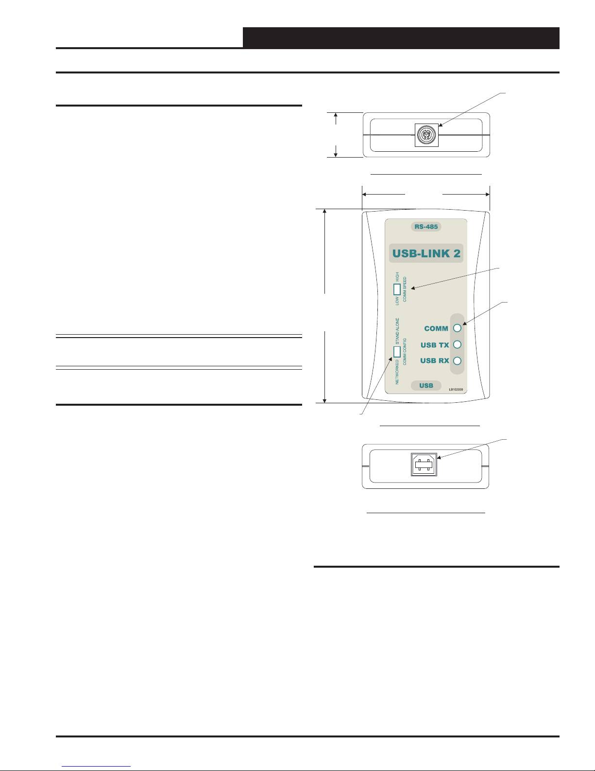
Female 6 Pin
Mini-DIN
Connector
1.06”
Top End View of USB-Link 2
2.31”
Communication
Speed Switch
LED - Typical
3.63”
STANDALONE
NETWORK
System Requirements
To enable the USB-Link 2 to work with Prism 2, you will need:
• USB-Link 2 with USB cable, mini-DIN male
communication cable, and adapters for terminal and
modular connections (cables and adapters provided)
• USB drivers on CD-ROM (supplied with USB-Link 2 but
also downloadable from any of our websites). Make sure to
install the drivers before connecting the USB-Link 2 to
your computer.
• PC with USB 1.1 or 2.0 port (supplied by others)
• Microsoft® Windows® 2000, Vista, 7, 8 & 10
• Prism 2 software version 4.0.4 or later (supplied with USB Link 2 but also downloadable from any of our websites)
Networked Systems Only
• CommLink(s) and/or MiniLink(s)
Configuration
Switch
Front View of USB-Link 2
Female Type B
USB Connector
Bottom End View of USB-Link
Figure 1: Top, Front, and Bottom Views of the
USB-Link 2
Technical Guide
3
Page 4

USB-LINK 2
Quick Guide
Important Notes
Follow the included USB-Link 2 driver installation
instructions (page 5).
Follow the connection and wiring instructions
(Figure 2, page 6) to connect and confi gure the
USB-Link 2.
If you use your USB-Link 2 on a network and after
installation you cannot view all controllers, you may
need an EPROM upgrade in your CommLink(s) and/
or MiniLink(s). See Troubleshooting in the back of
this guide on page 13 for further instructions.
Familiarize yourself with all system components and
review all documentation. Pay special attention to
“Cautions,” “Notes,” and “Warnings” since these may
keep you from experiencing unnecessary problems.
If you encounter any problems, please refer to the
Troubleshooting section of this guide fi rst. If you
can’t resolve the problem, please call WattMaster
Technical Support at our toll free number—
1-866-918-1100.
Quick Guide
Follow the fi ve steps below to get your USB-Link 2 up and running
in no time.
WARNING: You must install the USB drivers (Step 3 below)
before connecting the USB-Link 2 to your computer (Step 4 below).
Step 1: Set your USB-Link 2’s confi guration switch to Stand
Alone or Network (Figure 3, page 10).
Step 2: Set your USB-Link 2’s communication speed switch to
Low Speed or High Speed (Figure 3, page 10).
Step 3: Install the USB drivers from the included CD-ROM onto
your computer.
Step 4: Attach the USB cable to your USB-Link 2 and plug
the other end of the cable into your computer’s
USB port (Figure 2,page 6).
Step 5: Attach the communication cable to your USB-Link 2
and connect the other end of the cable to the
Controller’s communication port (Figure 2,page 6).
Step 6: Install the included Prism 2 software on your
computer (page 8).
4
Technical Guide
Page 5

USB-LINK 2
USB Driver Installation
USB Serial Converter and Serial Port
Driver Installation
The internal USB communication port of the USB-Link 2 uses a
specialized driver that must be installed on your Windows PC before
communication to the device can be established.
NOTE: You may already have this driver installed on your PC if
you are using a CommLink 5.
1. Before you begin, you must determine if your computer
is running 32-bit or 64-bit Windows. Open the System
information by clicking the
<Control Panel>, and clicking <System>. Under
System, you can view the system type. Based on what
type of system you have, you will choose 32_Bit.exe or
64_Bit.exe from the list of fi les shown in Step 10.
2. Insert the USB Drivers CD-ROM into your CD-ROM
drive or download the USB Drivers fi le from www.
orioncontrols.com/a/software/. If using the CD-ROM,
go to Step 7. If downloading the fi le, you will need to
scroll down the page until you fi nd “USB Drivers For
All Products” to download the driver fi les.
<Start> button, clicking
9. Double-click the folder “USBLink NewSS0073”.
10. The following list of fi les will display. Choose 32_Bit.
exe or 64_Bit.exe based on what type of system you
determined you have in Step 1.
3. Right click on “Click Here.” Then click
As> or <Save Target As> and select Desktop as the
destination.
4. Go to the “USB-DRIVERS-ALL.exe” fi le on your desk-
top. Double-click on this fi le and choose “Run” from the
options list. The following window will appear:
5. Select
6. Next, go to the C:\Temp\WM-USB-Drivers folder and
7. Click your
<Unzip> and the fi le will be unzipped to the
folder C:\Temp\WM-USB-Drivers folder by default.
now go to Step 9.
<Start> button and then click, <Computer>.
<Save Link
11. In the window that pops up, shown below, click
and the installation program will walk you through the
rest of the steps.
12. When successful installation has occurred, connect the
USB cable between the PC and the USB-Link 2. The
PC will automatically recognize the device and a COM
port will be assigned.
verify the Comm Port.
Follow the procedures on page 7 to
<Next>
8. Double-click on your CD-ROM drive. Open the Media
Files Folder.
Technical Guide
5
Page 6

USB-LINK 2
Connection and Wiring
Notes:
1. You Must
In Order To View A Single Controller Using Prism 2,
Disconnect The Communication Loop From The Controller Your USB-Link
Is Plugged Into
Set The Type Of CommLink In Prism 2 To USB Link Stand Alone, And
Cycle Power By Disconnecting And Reconnecting the USB Power Supply
Cable.
Connect The USB-Link 2 Mini D
Cable To The - IN
Connector On Controllers That Are
Supplied With Them.
Allows Communications With
Controllers That Are Connected To
The System When Network
Communication Is Chosen.
, Set The USB-Link Configuration Switch To Stand Alone,
NOTE:
-IN
This
All
RS-485 COMM
LOOP. WIRE
“R”TO “R”,
“T”TO “T”
“SHLD”TO “SHLD”
VCCX2 CONTROLLER
Orion No.: OE338-26B-VCCX2
BINARYINPUTS
BI1= PROOF OF AIRFLOW
= DIRTYFILTER
BI2
= HOOD ON/OFF
BI3
BI4
= REMOTE OCCUPIED
= REMOTE COOLING
BI5
= REMOTE HEATING
BI6
BI7
= REMOTE DEHUMIDIFICATION
BI8
= EMERGENCYSHUTDOWN
ANALOG INPUTS
= SPACETEMPERATURE
AI1
= SPACE SLIDE OFFSET
AI2
= SUPPLYAIR TEMPERATURE
AI3
= RETURNAIR TEMPERATURE
AI4
= BUILDING PRESSURE
AI5
I
= SUPPLYAIR TEMP RESET
A6
AI7
= OUTDOORAIR TEMPERATURE
AI8
= NOTCONNECTED USE DUCT
STATIC CONNECTOR
24 VAC POWER
ONLY
WARNING!
POLARITY
MUST BE
OBSERVED
OR THE
CONTROLLER
WILLBE
DAMAGED
GND
Female Mini D Plug
Mini-DIN Cable
Supplied With
USB-Link
Connect Mini-DIN Cable End
To Mini-DIN Port On USB-Link.
USB-Link 2
ALARM
DUCT
STATIC
+24VAC
M
MENU
www.aaon.com
MAIN SUPPLYFAN VFD =
ECONOMIZERACTUATOR =
MODULATING HEATING =
EXHAUSTFAN VFD =
DUAL
E-BUS
Controller With
Mini-DIN Plug
UP
ENTER
DOWN
www.orioncontrols.com
AAON No.: V87900
RELAYCONTACT
RATING IS 1AMP
MAX @ 24 VAC
MAIN FAN
RELAY2
RELAY3
RELAY4
RELAY5
RELAY6
RELAY7
RELAY8
RELAY
COMMON
BACNET–
=T
BACNETSHIELD
=SH
=R
BACNET+
AO1
AO2
AO3
AO4
WattMaster
Overlay
#S 000079
W
Rev.: 1A
Mini-DIN Cable
PL101904
Use The Adapter To Plug In To A Terminal Socket And Connect
The USB-Link 2 On Boards That Don’t Have A Female Mini-DIN Plug Connection.
This Only Allows Communications With The Board It Is Connected To
NOTE: .
Mini-DIN Cable
Use The Adapter And Wire To A Terminal Block
To Connect The USB-Link 2 To The Local Communications Loop
On Boards That Don’t Have A Female Mini-DIN Plug Connection.
NOTE:
Supplied With USB-Link 2
PL101905
Supplied With USB-Link 2
Adapter
P 101905L
This Allows Communications With
That Are Connected To The System
All Controllers
. See Note 1.
T
SHLD
R
T
SHLD
R
Adapter
PL101904
Computer
With Prism 2
Software
Installed
Communication Speed Switch
Must Be Set To Low or High Speed
Depending on Your Controller’s
Baud Rate.
STANDALONE
NETWORK
To USB Port On USB-Link 2.
Supplied With
Configuration Switch
Must Be Set To Stand Alone
Or Network Depending On Your
Installation.
Connect Type B Cable End
USB Cable
USB-Link 2
Figure 2: USB-Link 2 Connection & Wiring
6
Connect Type A Cable End To
USB Port On Desktop Or Laptop
NOTE:
Link 2 Must Be Installed On Your Computer
Personal Computer.
USB Drivers Supplied With The USB-
Before USB-Link 2 Can Be Used.
Technical Guide
Page 7

USB-LINK 2
Finding the COM Port Number
Finding What COM Port Number the
USB-Link 2 is Using
1. Left-click on <Start>, located on the bottom left of the
Windows toolbar. Select <Control Panel>. Double-click
the <System> icon.
2. Click the <Hardware> tab. Click the <Device
Manager> button.
3. Click on the plus sign next to Ports to see all of the COM
ports.
4. Locate the USB Serial Port (COM#). The COM# in
parentheses is the port it is located on. Write this COM port
number down. You will need to know this when setting up
the Prism 2 software.
Technical Guide
7
Page 8

USB-LINK 2
Prism 2 Setup Instructions
Confi guring Prism 2 for the USB-Link 2
1. Insert your Prism 2 software CD and follow the steps in the
readme.txt fi le to install the software.
2. The instructions will tell you to create a
Prism 2.exe shortcut on your desktop. Click
on this icon to open your Prism 2 software.
3. Click the <Login> button and type in the
level 3 User Name and password (default is
“admin, admin”). Click <Login>.
4. If Prism 2 is online, click the
<ON LINE> button to make it go
<OFFLINE>.
7. In the Serial Port fi eld, click on the pull down box and
select the COM port number that the USB-Link 2 is using.
8. In the Type of CommLink selection box, select the radio
button next to “CommLink 5 or USB Link II”.
9. In the Network Confi guration selection box, select the
mode for the USB-Link 2 you are using. If using stand
alone mode, select USB Link Stand Alone. If using network
mode, select USB Link Network. The position of the slide
switch on the USB-Link 2 must also be set to the mode you
are using (See Figure 3, page 10 for help in setting this
switch).
5. Click the <Job-Site> button to open the Job
Sites Window.
6. Click on any empty location in the Job-Site Selection
Window and type in a job name in the Selected
Location fi eld. Press <Enter>.
Your job site name will now appear in the Job-Site
Selection Window.
10. Click
11. Click the <OFFLINE> button to go
<Exit> to close out of the Job Sites Window.
<ON LINE>.
8
Technical Guide
Page 9

USB-LINK 2
Prism 2 Setup Instructions
12. From the <Communications> menu on the main toolbar,
select
<Search for Units>.
13. The Search For Units Window will appear. If you haven’t
performed a previous search, the Loop Selection fi eld
will read 01 and the Current Unit will read 00. You can
perform a selective search by entering the loop number
you would like to search and checking Search ONLY the
Selected Loop. The Check Unit Maps box will already be
checked. Do not deselect this box. Deselecting it will cause
the search not to work.
16. If Units Found on this Loop stays at zero, check the
wiring to the USB-Link 2 and the controller and/or read
through these directions again to make sure all steps were
followed. Refer to the Troubleshooting Section in the back
of this guide for further help.
17. To stop a search, click
18. Once you are done searching for units, close out of the
window or click <Exit>.
19. A window will pop up that asks, “Do you want to save
the search results?” Click <Yes> if you wish to save the
results. Click <No> if not.
20. You can now access any installed unit from the Main Prism
2 Screen by selecting a loop from the Loop Selection
Window with a single-click and by selecting the unit from
the Unit Selection Window with a double-click.
<Cancel Search>.
14. Click <Start Search> to initiate an automatic
detection of all installed controllers on your system.
15. If everything is working correctly, Units Found on this
Loop should increment. You will also see green boxes
indicating units that have been found.
Technical Guide
9
Page 10

USB-LINK 2
Communication Settings and LED Descriptions
Communication
Speed Switch
Configuration
Switch
STAND ALONE
NETWORK
LEDs
Figure 3: USB-Link 2 Confi guration Switch, Communication Speed Switch, and LEDs
Communication Speed
NOTE: Whenever you change the confi guration or
communication speed setting on the USB-Link 2,
you must cycle the power to the USB-Link 2 by
disconnecting and reconnecting the USB power
supply cable.
The communication speed switch for low or high speed is found to the
left of the LEDs. See Figure 3 above. To set the communication speed
switch, insert a pen tip to move the switch up or down.
Low Speed - The switch should be set to LOW if using VCM-X or
older generation Orion Controllers, older generation Auto-Zone
Controllers, or VCB-X or GPC-XP Controllers set to Low Speed.
USB-Link 2 Switch Settings
High Speed - The switch should be set to HIGH if using AZ2
Confi guration Switch
The confi guration switch for stand alone or network mode is found to the
left of the LEDs. See Figure 3 above. To set the confi guration switch,
insert a pen tip to move the switch up or down.
Stand Alone - No MiniLink or CommLink - The slide switch
on the USB-Link 2 should be set to “Stand Alone” when you are
trying to talk to a stand alone controller or multiple controllers on
a loop without a CommLink or a MiniLink wired to the
communications loop.
Network - MiniLink or CommLink connection - The slide
switch on the USB-Link 2 should be set to “Network” any time
there is a CommLink or MiniLink wired to the communications
loop.
Controllers, VCCX2/VCC-X Controllers, or VCB-X and GPC-XP
Controllers set to High Speed.
USB-Link 2 LED Descriptions
COMM - Indicates communication activity between the USB-Link
2 and the controller(s) that the USB-Link 2 is connected to.
When this LED is fl ashing, data is being exchanged.
USB TX & USB RX - Indicates communication activity between
the USB-Link 2 and the computer that the USB-Link 2 is connected to. The LEDs will fl ash only when data is sent from Prism
2 to the USB-Link via USB.
10
Technical Guide
Page 11

USB-LINK 2
Troubleshooting
Troubleshooting Tips
Problems with Prism 2 Software
• Verify that the correct USB serial port created by the
USB connection is selected in the Job-Sites Window.
Verify the COM port number in
<System>,<Hardware>,<Device Manager>,
<Ports>.
• Verify that USB-Link 2 is selected for Type of CommLink
in the Job Sites Window.
• Verify that the correct USB-Link 2 mode is selected
under Network Confi guration in the Job-Sites Window.
Problems with USB Connection
• Verify that the USB-Link 2’s USB LEDs blink when you
perform a Search for Units or try to open a status screen in
Prism 2.
• If the USB-Link 2’s USB LEDs fail to blink, disconnect and
reconnect the USB connection.
<Control Panel>,
Problems with RS-485 Wiring
• Make sure T connects to T, R to R, and Shld to Shld if
multiple boards are wired together on a loop.
• Make sure that the USB-Link 2 mini-DIN communication
cable is plugged into a controller or wired to the local
side of the loop.
Problems Viewing Controllers on a Network
• Make sure that in Prism 2, USB Link Network is
selected under Network Confi guration in the Job-Sites
Window.
NOTE: WattMaster Controls Technical Support cannot trouble-
shoot internal PC and/or Windows®-based operating
system problems.
• If the problem persists, check that the USB drivers
have been installed properly
Technical Guide
11
Page 12

Form: WM-USBLII-TGD-01G Printed in the USA December 2017
All rights reserved. Copyright 2017
WattMaster Controls, Inc. 8500 NW River Park Drive Parkville, MO 64152
Phone (816) 505-1100 www.wattmaster.com Fax (816) 505-1101
 Loading...