

Page 1
www.wattmaster.com
MUA II Controller
Technical Guide
Page 2

Table of Contents
Controller Overview ......................................................................................................................................... 3
Features .......................................................................................................................................................................................3
Controller Inputs and Outputs ......................................................................................................................... 6
General.........................................................................................................................................................................................6
MUA II Controller Analog Inputs ...................................................................................................................................................6
Relay Outputs...............................................................................................................................................................................6
Analog Output ..............................................................................................................................................................................6
Controller Installation & Wiring ...................................................................................................................... 7
General.........................................................................................................................................................................................7
Controller Mounting ......................................................................................................................................................................7
Important Wiring Considerations ..................................................................................................................................................7
Expansion Board Installation & Wiring ........................................................................................................... 9
Jumper Settings ...........................................................................................................................................................................9
Wiring Considerations ................................................................................................................................................................10
Wiring Details ................................................................................................................................................. 11
Space Temperature Sensor ........................................................................................................................................................ 11
Supply Air Temperature Sensor ..................................................................................................................................................12
Outside Air
Remote Occupied Contact ........................................................................................................................................................13
Outside Air Humidity Sensor .....................................................................................................................................................14
Space Humidity Sensor ..............................................................................................................................................................15
Fan Proof of Flow Switch ...........................................................................................................................................................15
Temperature Sensor .................................................................................................................................................13
Start-up & Commissioning............................................................................................................................. 16
Controller Addressing .................................................................................................................................................................16
Power Wiring .............................................................................................................................................................................16
Initialization.................................................................................................................................................................................17
Programming The Controller ......................................................................................................................................................17
Sequence of Operations ................................................................................................................................ 18
MUA Operation Overview ...........................................................................................................................................................18
MUA Modes ................................................................................................................................................................................18
Initialization.................................................................................................................................................................................21
MUA II Confi guration & Setup ....................................................................................................................................................21
Scheduling..................................................................................................................................................................................22
Force Modes or Overrides..........................................................................................................................................................23
Internal Trend Logging ...............................................................................................................................................................23
Troubleshooting ............................................................................................................................................. 24
Using LED’s To Verify Operation ................................................................................................................................................24
Appendix ........................................................................................................................................................ 26
WattMaster Controls Inc.
8500 NW River Park Drive · Parkville , MO 64152
Toll Free Phone: 866-918-1100
PH: (816) 505-1100 · FAX: (816) 505-1101 · E-mail: mail@wattmaster.com
Visit our web site at www.wattmaster.com
Form: WM-MUAII-TGD-01A Copyright 2009 WattMaster Controls, Inc.
WattMaster Controls, Inc. assumes no responsibility for errors, or omissions.
This document is subject to change without notice.
Page 3
Controller Overview
MUA II Controller
Features
The MUA II Controller Board is designed with 5 usable analog inputs
and 5 relay outputs. The controller’s input and output capabilities can
be expanded by use of either 2-slot or 4-slot expansion boards that plug
into the MUA II Controller by means of a modular cable. The MUA II
Controller is designed for use with Makeup Air HVAC units. Features
include the following:
• Up to 8 Stages of Cooling (4 on board, 4 more with
expansion board)
• Up to 8 Stages of Heating (4 on board, 4 more with
expansion board)
• External Modulating Heat
• Fan Proving Interlock
• Supply Air Setpoint Reset From Temperature Input
• Dewpoint Setpoint Reset From Humidity Input
• Accepts Remote Occupied Signal
• De-Humidifi cation Capable
• 7-Day, 2-Event-Per-Day Scheduler Built In
• 14-Day Holiday Scheduler Built In
• Internal Trend Logging
Most makeup air control confi gurations can be confi gured with the
standard MUA II Controller. If the application requires more outputs,
optional relay expansion boards are available from the factory to
provide for additional relay outputs as required. These expansion
boards are installed on the MUA II Controller board via a modular
cable connection.
The available expansion board configurations allow for up to 16
additional binary (relay) outputs. The various expansion boards connect
to the expansion board base. Jumpers must be set according to the board
type installed. Up to 4 Relay Output Expansion Boards can be installed
on the expansion base board connected to the controller.
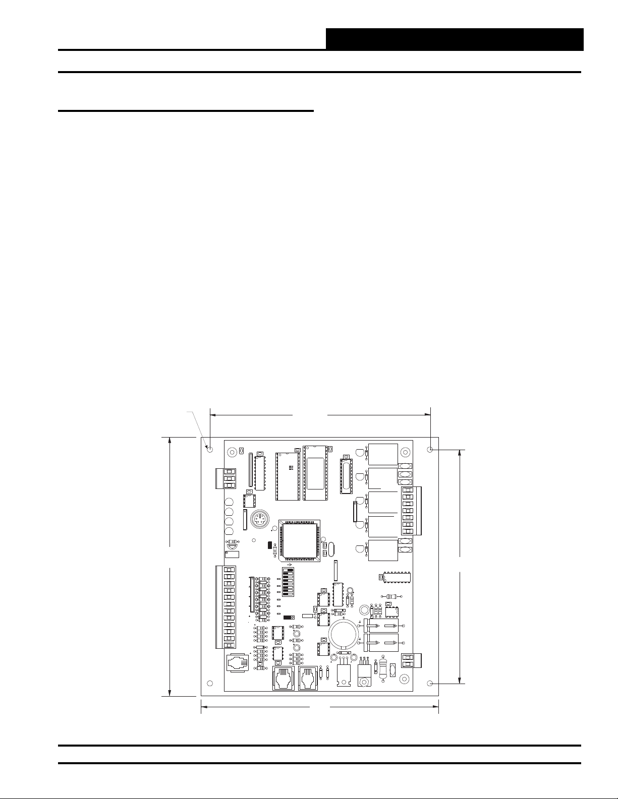
.20 Dia.
Typ. of 4
7.3”
C21
TB1
COMM
T
SHLD
R
CX5
LD6
COMM
LD7
PWR
LD8
LED1
LD9
LED2
R1
U7
RV1
VREFADJ
INPUTS
+VDC
AIN1
AIN2
AIN3
AIN4
AIN5
GND
GND
AOUT1
AOUT2
AIN7
GND
PJ1
TB3
PRESSURE
SENSOR
CX1
RN1
1
U5
RS-485
COMM
1
RN3
P1
+VREF
5.11V
TESTPOINT
EWDOG
RN5
C10
C12
C17
R26
EXPANSION
6.2“
U3
CX2
U2
U1
RAM
HH
U6
C1
R28
ADD
ADDRESS
1
2
4
PU1
8
D6
16
PU2
32
D7
TOKEN
PU3
NETWORK
D8
PU4
SW1
D9
PU5
D11
PU7
D14
D15
C20
PJ2
X2
0-1
0-5
VDC
VDC
JP1
U13
R15
C14
R19
CX13
U15
C15
R22
R24
R25
CX15
PJ3
EPROM
TUC-5RPLUS
YS101816REV. 2
U10
C11
U14
D17
CX3
(1MEG)
CX6
C2
C3
CX10
CX12
U12
CX14
D18
C18
T'STAT
D1
CX4
U4
RLY1
D2
RLY2
D3
PAL
1
RLY3
D4
RN2
RLY4
D5
X1
RLY5
1
RN4
U9
C7
D10
R7
L1
D13
D12
R13
SC1
D19
C19
VR1
VR2
CX8
R10
D16
COM1-3
COM4-5
R6
R11
R27
V6
C9
R1
R2
R3
R4
R5
U8
V1
V2
V3
V4
V5
U11
C13
C16
TB4
GND
POWER
24VAC
TB2
6.6”
6.7”
Figure 1: MUA II Controller Dimensions
Technical Guide 3
Page 4
MUA II Controller
Controller Overview
2.12
TB2
TB1
C6
GND
24VAC-IN
PWR
LD1
R14
D3
VR2
VR3
4.73
VR4
VR5
VR6
R13
MC
7824CT
CX3
MC
7805ACT
MC
7812CT
MC
7824CT
MC
7824CT
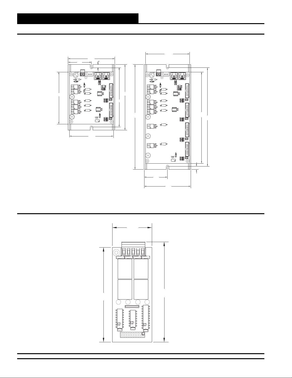
2-Slot Expansion
Base Board
C1
C2 C3
C4 C5
4.24
GND
+24VDC-OUT
YS101780
4.00
4.00
0.28
TB2
TB1
GND
+24VDC-OUT
24VAC-IN
GND
PJ2
PJ1
R11
R9
D2D1 R8
R7
P1
U1
P82B715P
CX1
JP1
R1
R2
R3
U2
P2 JP2
LM358N
CX2
VR1
R10
R4
2 SLOT MODULAR I/O
R5
R6
R12
5.96
5.40
C8
VR2
VR3
VR4
VR5
VR6
9.52
VR7
VR8
LD1
PWR
R20
D3
7824CT
7805ACT
7812CT
7824CT
7824CT
7824CT
7824CT
4 SLOTMODULAR I/O BD.
YS101782
PJ2
PJ1
R17
R19
CX3
R15
D1
D2
C1
R13
R14
P1
U1
P82B715P
C2
C3
C4
C5
C6
C7
CX1
JP1
R1
R2
R3
U2
P2
LM358N
CX2
JP2
R5R4 R6
P3
JP3
R9R8R7
P4
VR1
R16
JP4
R10
R11
R12
R18
8.29
8.96
Figure 2: Expansion Base Board Dimensions
V4
4RLY IO BD.
K4
YS101790
4.00
K3
K4
OMRON
24VDC
G5L-114P-PS
OMRON
24VDC
G5L-114P-PS
K3
RN1
1.67
UL 5A250VAC
CONTACT:
UL 5A250VAC
CONTACT:
K2
OMRON
24VDC
G5L-114P-PS
OMRON
24VDC
G5L-114P-PS
K1
2.12
4-Slot Expansion
Base Board
TB1
V1
UL 5A250VAC
CONTACT:
K1
4.24
UL 5A250VAC
CONTACT:
K2
0.28
4.24
Figure 3: Relay Expansion Board Dimensions
4
U3
CX3
PCF8574P
74HC04N
ULN2803A/
CX2
PHILIPS
TL
HA
AN
ID
U1
CX1
P1
U2
Technical Guide
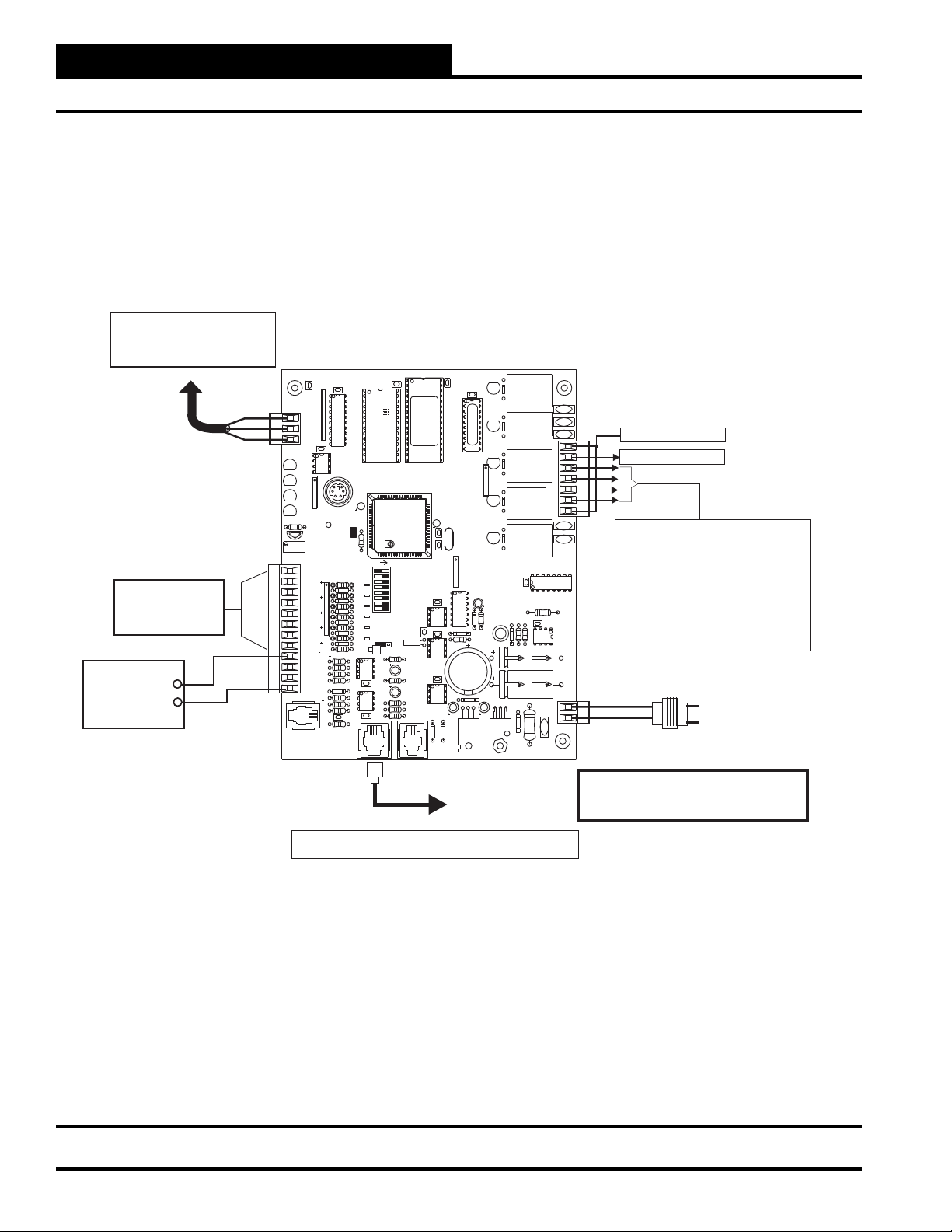
Page 5
MUA II Controller
Controller Overview
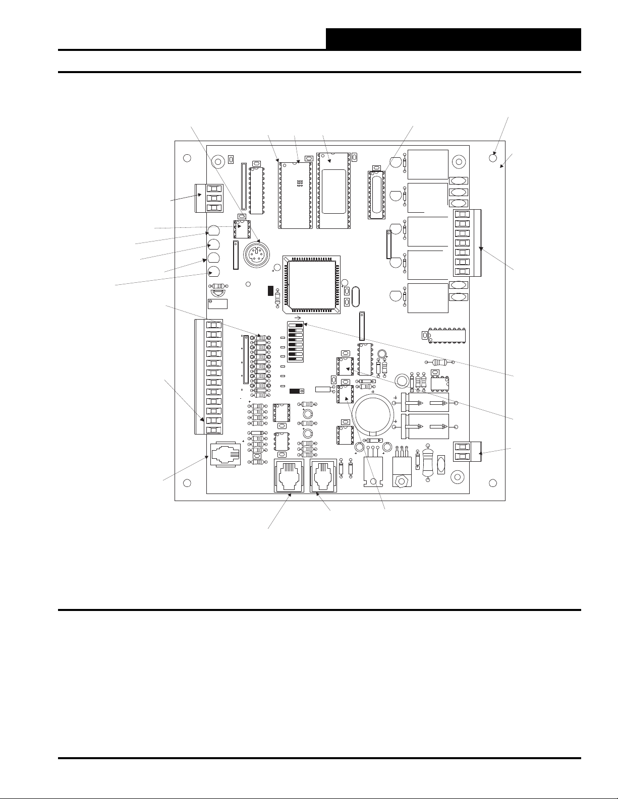
RS-485
Communications
Loop Connection
RS-485
Communications
Driver Chip
Comm
LED
Power
LED
Diagnostic
Blink Code
LED
Pull-up Resistors
For Analog Inputs
Analog Input
And Output
Terminal Block
Pressure Sensor
(AIN6 Modular Connection)
Not
Used
Modular Service
Tool - Mini Din
Connector
C21
TB1
COMM
T
SHLD
R
CX5
LD6
COMM
LD7
PWR
LD8
LED1
LD9
LED2
R1
U7
RV1
VREF ADJ
INPUTS
+VDC
AIN1
AIN2
AIN3
AIN4
AIN5
GND
GND
AOUT1
AOUT2
AIN7
GND
PJ1
TB3
PRESSURE
SENSOR
Typical
Pin 1
Indicator
CX1
RN1
1
U1
U5
RS-485
COMM
1
RN3
P1
+VREF
5.11V
TEST POINT
EWDOG
RN5
C10
C12
D15
C17
C20
R26
EXPANSION
Mounting Hole
EPROM
RAM
Chip
Chip
ADD
1
2
4
8
16
32
TOKEN
NETWORK
VDC
JP1
PJ3
X2
R15
C14
R19
C15
R22
R24
R25
U3
EPROM
TUC-5R PLUS
YS101816 REV.2
C2
CX10
U10
C11
U12
CX14
U14
D17
T'STAT
(1 MEG)
C3
CX3
CX4
U4
PAL
1
RN2
CX6
X1
1
RN4
U9
C7
D10
CX12
D12
R13
SC1
D19
D18
C19
C18
VR1
CX2
U2
RAM
HH
U6
C1
R28
ADDRESS
PU1
D6
PU2
D7
PU3
D8
PU4
SW1
D9
PU5
D11
PU7
0-1
0-5
VDC
D14
U13
CX13
U15
CX15
PJ2
PAL
Chip
D1
RLY1
D2
RLY2
D3
V1
V2
V3
COM1-3
R1
R2
RLY3
D4
R3
R4
R5
RLY4
RLY5
R7
COM4-5
D5
CX8
L1
R10
D13
D16
TB2
V4
V5
U8
R6
C9
R11
U11
C13
C16
TB4
GND
R27
V6
POWER
24VAC
VR2
Typof4
Mounting
Backplate
Relay Output
Terminal Block
Address Switch
EEPROM
24 VAC
Power Input
Expansion Board
(Modular Connection)
Figure 4: MUA II Controller Component Locations
Technical Guide
Not Used
Real Time
Clock Chip
5
Page 6

MUA II Controller
Controller Inputs and Outputs
General
The following inputs and outputs are available on the MUA II Controller
and/or the relay expansion boards that can be added to the main controller board expansion port. For component locations of the inputs on the
MUA II Controller, see Figure 4. For wiring of inputs and outputs, see
Figure 5 and 6.
MUA II Controller Analog Inputs
Input #1 - Reset Temperature Sensor
A space temperature sensor can be connected here and used for modulation of the Supply Air Setpoint. At a specifi ed Space Temperature
Setpoint, the Supply Air Setpoint will be reset towards the Maximum
Supply Air Temperature Setpoint.
Input #2 - Supply Air Temperature
The Supply Air Temperature Sensor is connected to this input. This
sensor is used to control heating and cooling staging.
Input #3 - Remote Occupied Contact
This input can be confi gured to monitor a contact closure from another
building automation system which indicates that the equipment should be
operating in the occupied mode. If the remote occupied signal is being
monitored, you must program all the internal schedules to be zero for
both the start and stop times on every day of the week.
Input #4 - Outdoor Air Temperature
The Outdoor Air Temperature Sensor is connected to this input. The
Outdoor Air Temperature Sensor is used to initiate the heating, cooling,
and vent modes of operation. It is also used in combination with the
outdoor air humidity to calculate the Dewpoint Temperature.
Input #5 - Outdoor Air Humidity
This input is used for an Outdoor Air Humidity Sensor that, combined
with the outdoor air temperature, is used to calculate a Dewpoint Temperature for the purpose of dehumidifi cation.
Input #7 - Fan Proof of Flow Switch
or Reset Humidity Sensor
A Proof of Flow Switch that provides a contact closure whenever the fan
is moving air can be monitored on this input. If this contact opens while
the fan is on, all heating and cooling is suspended. This is an optional
item. If a switch is installed, you must confi gure the MUA II to utilize
the signal. If this option is not confi gured, the unit will default to reset
humidity input. An indoor Humidity Sensor can be installed on this
input instead of the Proof of Flow Switch. This extra Humidity Sensor
is used to provide for reset of the Dewpoint setpoint.
Relay Outputs
Relay #1 - Fan (Enable)
This is a non-confi gurable output.
Relay #2 - #5 Confi gurable Relays
These relays are located on the MUA Controller. Confi guration order
and options are the same as for relays #6 through #21 as outlined in the
information for these relays that follows.
Relay #6 - #21 Confi gurable Relays
These relays are available by using Relay Expansion boards connected
to the MUA II Controller. Relays can be confi gured in any order, but we
recommend that they be confi gured in the following order:
1. Heating (aux. heating) stages
2. Cooling (compressor) stages
3. Gas Reheat Control for De-Humidifi cation
4. External Heat Enable
You can have up to 8 stages of Heating (aux. heating) and 8 stages of
Cooling (compressors) as well as individual relays assigned to options
3 and 4 above.
Analog Output
Input #6 - Not Used
6
AOUT1
The MUA II Controller has 1 Analog Output available. The usable output
is located at terminal AOUT1 and is used for controlling an external
heating device. Voltage ranges for this output are user-confi gurable for
either a 0-10 VDC or 2-10 VDC signal.
Technical Guide
Page 7

MUA II Controller
Controller Installation & Wiring
General
Correct wiring of the MUA II Controller is the most important factor in
the overall success of the controller installation process. In general, most
MUA II Controllers are factory installed and wired. It is also possible to
purchase these controllers directly from WattMaster Controls for installation in the fi eld. Some of the following information pertains to fi eld
wiring and may not apply to your installation since it was pre-wired at
the factory. However, in the unlikely event that troubleshooting of the
controller is required, it is a good idea to be familiar with the system
wiring, no matter if it was factory or fi eld wired.
Controller Mounting
When the controller is to be fi eld mounted, it is important to mount the
controller in a location that is free from extreme high or low temperatures,
moisture, dust, and dirt. It is recommended that it be installed in the
HVAC unit control panel. If this is not practical, it should be mounted
in a separate control enclosure that is weathertight. Be careful not to
damage the electronic components when mounting the controller. Remove the controller from its backplate. Mark the control enclosure base
using the backplate as a template. Drill pilot holes in the enclosure base
and secure the backplate to it using sheet metal screws. Do not allow
metal shavings to fall onto the circuit board. Reattach the controller to
the backplate.
Important Wiring Considerations
Please carefully read and apply the following information when wiring
the MUA II Controller. See Figure 5 for MUA II Controller wiring
diagram.
1. All 24 VAC wiring must be connected so that all ground
wires remain common. Failure to follow this procedure
can result in damage to the controller and connected
devices.
2. All wiring is to be in accordance with local and national
electrical codes and specifi cations.
3. Minimum wire size for 24 VAC wiring should be 18 gauge.
4. Minimum wire size for all sensors should be 24 gauge.
Some sensors require 2-conductor wire and some require
3-conductor.
5. Be sure that all wiring connections are properly inserted
and tightened into the terminal blocks. Do not allow wire
strands to stick out and touch adjoining terminals which
could potentially cause a short circuit.
6. When communication wiring is to be used to interconnect
controllers together or to connect to other communication
devices, all wiring must be minimum 18-gauge,
2-conductor, twisted pair with shield.
7. Before applying power to the MUA II Controller, be sure
to recheck all wiring connections and terminations
thoroughly.
Technical Guide
7
Page 8
MUA II Controller
Controller Installation & Wiring
Connect To Next Controller And/Or
MiniLink PD On Local Loop
For Stand Alone Applications
Connect To System Manager
All Comm Loop Wiring Is
Straight Thru
TtoT
RtoR
SHLD to SHLD
Analog Inputs
See Individual Sensor
Wiring Diagrams For
Detailed Sensor Wiring
0-10 VDC
0r 2-10 VDC
Connect To
External Heat
Device If Used
Local Loop RS-485
9600 Baud
+
_
C21
CX1
RN1
1
TB1
COMM
T
SHLD
R
CX5
U5
LD6
INPUTS
TB3
RS-485
COMM
COMM
LD7
1
PWR
LD8
LED1
RN3
LD9
LED2
R1
+VREF
5.11V
TESTPOINT
U7
RV1
VREFADJ
+VDC
RN5
AIN1
AIN2
AIN3
AIN4
AIN5
C10
GND
GND
C12
AOUT1
AOUT2
AIN7
C17
GND
PJ1
PRESSURE
SENSOR
EXPANSION
Note: All Temperature Sensors Must Be Thermistor Type III Which
Provide 10K Ohms Resistance @77 Deg. F
U2
U1
RAM
HH
C1
P1
EWDOG
R28
ADDRESS
PU1
D6
PU2
D7
PU3
D8
SW1
PU4
D9
PU5
D11
PU7
0-5
VDC
D14
U13
CX13
D15
U15
C20
CX15
R26
PJ2
MUA II Controller
CX2
U6
PHILIPS
ADD
1
2
4
8
16
32
TOKEN
NETWORK
X2
0-1
VDC
JP1
R15
C14
R19
C15
R22
R24
R25
PJ3
U3
EPROM
TUC-5RPLUS
YS101816REV. 2
U10
C11
U14
D17
T'STAT
C2
CX10
U12
CX14
(1MEG)
CX6
C3
CX12
D18
CX3
X1
C18
Connect To
Expansion Board
Base (When Used)
D1
CX4
U4
RLY1
D2
RLY2
D3
PAL
1
RLY3
D4
RN2
RLY4
D5
RLY5
1
RN4
U9
C7
D10
R7
L1
R10
D13
D12
R13
SC1
D19
C19
7824CT
M
VR1
VR2
CX8
D16
COM1-3
COM4-5
R11
R27
V1
V2
R1
R2
R3
R4
R5
U8
NE5090NPB3192
0PS
R6
C9
9936
U11
MC34064A
C13
C16
GND
V6
POWER
24VAC
V3
TB2
V4
V5
TB4
R - 24VAC
G - Fan ON/OFF Only
Relay Output Dry Contacts
R2 Thru R5 May Be User Configured For
The Following:
1 - Heating (Aux. Heating)Stages
2 - Cooling (Compressor) Stages
3 - Gas Reheat Control For Dehumidification
4 - External Heat Enable
Note: Up To 16 More Relays Are Available
By Adding Relay Expansion Boards. All
Expansion Board Relay Outputs Are User
Configurable As Listed Above.
GND
24VAC
Required VA For
Transformer = 8VA
Warning:
24 VAC Must Be Connected So That All Ground
Wires Remain Common. Failure To Do So Will
Result In Damage To The Controllers.
Line Voltage
Figure 5: MUA II Controller Wiring
8
Technical Guide
Page 9
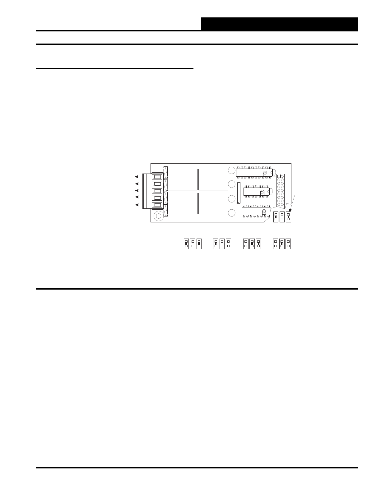
Expansion Board Installation & Wiring
Jumper Settings
The expansion boards are connected to the MUA II Controller with
a modular cable. Up to 2 Expansion Base Boards can be populated
with expansion boards to provide additional inputs and outputs. The
expansion boards can be placed on the expansion base board in any
order; however, the jumpers on the Expansion Base Board must be set
correctly for proper operation. See Figure 6 for correct jumper settings
and jumper locations.
4 Relay Output Expansion Board
Relay Outputs - 6 Through 21
N.O. Contact #6 - Configurable
N.O. Contact #7 - Configurable
N.O. Contact #8 - Configurable
N.O. Contact #9 - Configurable
TB1
Common
V1
V4
4RLY IO BD.
Relays 6-9 Relays 10-13
MUA II Controller
K1
UL 5A250VAC
CONTACT:
24VDC
G5L-114P-PS
OMRON
UL 5A250VAC
CONTACT:
24VDC
G5L-114P-PS
OMRON
K4
YS101790
K2
UL 5A250VAC
CONTACT:
K1
24VDC
G5L-114P-PS
OMRON
K2
UL 5A250VAC
CONTACT:
24VDC
G5L-114P-PS
K3
RN1
OMRON
K3
K4
Relays 14-17 Relays 18-21
CX1
ULN2803A/
74HC04N
PCF8574P
P1
PHILIPS
TL
HA
AN
ID
U1
CX2
U2
Address Jumpers
Jumpers
Under
Expansion
Board To Be
Set As Shown
Figure 6: Expansion Board Jumper Settings
Technical Guide
9
Page 10

MUA II Controller
Expansion Board Installation & Wiring
Wiring Considerations
The expansion base boards must be connected to 24 VAC as shown in
the wiring diagram below. As noted below, the power requirement for
a two-slot base board is 10 VA. A four-slot base board requires 20 VA.
Be sure that the transformer used for powering the base boards meets
these minimums. See Figure 7 for complete wiring details.
Observe Polarity! All boards must be wired with GND-to-GND and 24VAC-to-24VAC.
Failure to observe polarity will result in damage to one or more of the boards. Expansion
Boards must be wired in such a way that power to both the expansion boards and the
controller are always powered together. Loss of power to the expansion board will cause the
controller to become inoperative until power is restored to the expansion board.
Relay Output #6 - Configurable (N.O. Dry Contact)
Relay Output #7 - Configurable (N.O. Dry Contact)
Relay Output #8 - Configurable (N.O. Dry Contact)
Relay Output #9 - Configurable (N.O. Dry Contact)
Relay Output #10 - Configurable (N.O. Dry Contact)
Relay Output #11 - Configurable (N.O. Dry Contact)
Relay Output #12 - Configurable (N.O. Dry Contact)
Relay Output #13 - Configurable (N.O. Dry Contact)
Common
Common
WARNING!!
24VAC
POWER
INPUT
GND
4RLY IO BD.
4RLY IO BD.
24VAC
YS101790
YS101790
Connect to
MUA
Controller Board
Relay Output #14 - Configurable (N.O. Dry Contact)
Relay Output #15 - Configurable (N.O. Dry Contact)
Relay Output #16 - Configurable (N.O. Dry Contact)
Relay Output #17 - Configurable (N.O. Dry Contact)
Relay Output #18 - Configurable (N.O. Dry Contact)
Relay Output #19 - Configurable (N.O. Dry Contact)
Relay Output #20 - Configurable (N.O. Dry Contact)
Relay Output #21 - Configurable (N.O. Dry Contact)
Figure 7: Expansion Board Wiring
10
Common
Common
4RLY IO BD.
4RLY IO BD.
YS101790
YS101790
Technical Guide
Page 11

Space Temperature Sensor
A Space Temperature Sensor is used with the MUA II Controller to
provide for Supply Air Temperature Reset. At a specifi ed Space Temperature Setpoint, the Supply Air Setpoint will be reset towards the
Maximum Supply Air Temperature Setpoint. For more information on
the operation of this sequence, see the Sequence of Operation section of
this manual. This sensor is a 10K Type III thermistor sensor. See Figure
8 for complete sensor wiring details.
Space Temperature Sensor
TMP
GND
MUA II Controller
Wiring Details
INPUTS
+VDC
AIN1
AIN2
AIN3
AIN4
AIN5
GND
GND
AOUT1
AOUT2
AIN7
GND
Figure 8: Space Temperature Sensor Wiring
MUA II Unit Controller Board
Technical Guide
11
Page 12

MUA II Controller
Wiring Details
Supply Air Temperature Sensor
The Supply Air Temperature Sensor should be mounted in the unit
discharge plenum or in the supply air duct.
The Supply Air Temperature Sensors are 10K Type III thermistor sensors.
Supply
Air Temperature
Sensor
Mount In MUA
Unit Supply
Air Duct
INPUTS
+VDC
AIN1
AIN2
AIN3
AIN4
AIN5
GND
GND
AOUT1
AOUT2
AIN7
GND
Figure 9: Supply Air Temperature Sensor Wiring
12
MUA II Controller Board
Technical Guide
Page 13

MUA II Controller
GND
INPUTS
GND
AOUT1
AOUT2
GND
+VDC
AIN1
AIN2
AIN3
AIN4
AIN5
AIN7
MUA II Controller Board
Remote Occupied
Contact
(Relay By Others)
Wiring Details
Outside Air Temperature Sensor
The Outside Air Sensor must be wired as shown in the illustration
below for proper operation. The Outside Air Temperature Sensor is a
10K Type III thermistor sensor. The sensor should be mounted in the
upright position as shown in an area that is protected from the elements
and direct sunlight. Be sure to make the wiring splices inside of the
Outside Air Temperature Sensor weathertight enclosure. See Figure
10 for detailed wiring.
Outdoor
Air Temperature
Sensor
Make Splice Connections
Inside Sensor Enclosure
As Shown. Seal All
Conduit Fittings With
Silicone Sealant.
Mount Sensor Outdoors
In Shaded Protected
Area & In Upright
Position As Shown
Caution: Be sure to mount the Outside Air Sensor in
an area that is not exposed to direct sunlight. A
shaded area under the eve of the building or
under the HVAC unit rainhood is normally a
good location. If the sensor is not located as
specifi ed, erroneous outside air temperature
readings will result. Unused conduit opening(s)
must have closure plugs installed and must be
coated with sealing compound to provide rain
tight seal. Water can damage sensor!
INPUTS
+VDC
AIN1
AIN2
AIN3
AIN4
AIN5
GND
GND
AOUT1
AOUT2
AIN7
GND
Figure 10: Outside Air Temperature Sensor Wiring
Remote Occupied Contact
A Remote Occupied contact closure supplied from another Building
Automation System device can be used to enable Occupied and Unoccupied modes on the MUA II Controller. This relay contact must be
a dry contact and be wired as shown below. See Figure 11 below for
detailed wiring.
Figure 11: Remote Occupied Contact Wiring
Technical Guide
13
Page 14

MUA II Controller
Wiring Details
Outside Air Humidity Sensor
If you want to install a humidity sensor onto the MUA II Controller, it
is important that you follow these instructions. There are 2 terminals
labeled “H+” and “H-”. Terminal “H+” will connect to the connection
labeled “+VDC” on the analog input block. See Figure 12. Terminal
“H-” connects to the connection labeled “AIN 5” on the analog input
block. Also, the resistor labeled “PU5” needs to be removed. Lastly, a
supplied 250 Ohm, ¼ Watt, 1% resistor needs to be installed between
“AIN 5” and “GND”. See Figure 12 for detailed wiring.
Outdoor
Air Humidity
Sensor - 4-20mA
H+(T1)
H-(T4)
Seal All Conduit Fittings
With Silicone Sealant.
250 Ohm
Resistor
(Shipped With Sensor)
To be Installed Between
AIN5 and GND
MUA II Controller Board
Warning: It is very important to be certain that all wiring is
correct as shown in the wiring diagram below.
Failure to observe the correct polarity will result in
damage to the Humidity Sensor or controller.
The Pull-up Resistor (PU5)
INPUTS
+VDC
AIN1
AIN2
AIN3
AIN4
AIN5
GND
GND
AOUT1
AOUT2
AIN7
GND
Must Be Removed
When Using A 4-20ma Device
If YouAre Using The Standard Factory Supplied Humidity Sensor, It
Has Terminals Labeled “H+ (T1)” And “H- (T4)”. Terminal “H+ (T1)” Is
The Voltage Input And Should Be Connected To The Terminal Labeled
+VDC On The VAV/CAV Controller. Terminal “H- (T4)” Is The 4-20 Ma
Output Signal And Should Be Connected To The Terminal Labeled AIN
5 On The VAV/CAV Controller.
Should Be Connected Between AIN 5 AndA Ground Terminal On The
VAV/CAV Controller.
Factory Is Used, Refer To The Wiring Instructions Shipped With The
Sensor.
Figure 12: Humidity Sensor Wiring
A Factory Supplied 250 Ohm Resistor
If A Sensor Other Than The One Supplied By The
14
Technical Guide
Page 15

MUA II Controller
Wiring Details
Space Humidity Sensor
A Space Humidity Sensor or a Fan Proof of Flow Switch can be connected to AIN7 on the MUA II Controller. Shown below is the Space
Humidity Sensor wiring.
If YouAre Using The Standard Factory Supplied Humidity Sensor, It Has
Terminals Labeled “+ (T1)”And - (T2)”. Terminal + (T1)” Is The Voltage
Input And Should Be Connected To The Terminal Labeled +VDC On The
MUA II Controller. Terminal “- (T2)” Is The 4-20 Ma Output Signal And
Should Be Connected ToThe Terminal Labeled AIN7 On The MUA II
Controller.
A Factory Supplied 250 Ohm Resistor Should Be Connected
Between AIN 7 AndA Ground Terminal On The MUAII Controller.
Sensor Other Than The One Supplied By The Factory Is Used, Refer To
The Wiring Instructions Shipped With The Sensor.
+ (T1)
- (T2)
250 Ohm
Resistor
(Shipped With Sensor)
To be Installed Between
AIN7 and GND
If A
Figure 13: Space Humidity Sensor Wiring
The Pull-up Resistor (PU7)
Must Be Removed
When Using A 4-20ma Device
INPUTS
+VDC
AIN1
AIN2
AIN3
AIN4
AIN5
GND
GND
AOUT1
AOUT2
AIN7
GND
MUA II Controller Board
Fan Proof of Flow Switch
If a Fan Proof of Flow Switch is required, then obviously the Space
Humidity Sensor option is not available. By the same token, if a Space
Humidity Sensor is required, then the Fan Proof of Flow Switch option
is not available. See Fan Proof of Flow Switch wiring below.
INPUTS
+VDC
AIN1
AIN2
AIN3
AIN4
AIN5
GND
GND
Fan Proof Of Flow
Switch
MUA II Controller Board
Figure 14: Fan Proof of Flow Switch Wiring
AOUT1
AOUT2
AIN7
GND
Technical Guide
15
Page 16

MUA II Controller
Start-up & Commissioning
In order to have a trouble free start-up, it is important to follow a few
simple procedures. Before applying power for the fi rst time, it is very
important to correctly address the controller and run through a few
simple checks.
Controller Addressing
All MUA II Controllers are equipped with address switches. If the MUA
II Controller is to operate as a stand-alone system (not connected to any
other controllers), the controller address switch should be set for address
1. When using the Modular Service Tool or System Manager to program
and confi gure the MUA II Controller, you would enter this address to
communicate with the controller. When the system is to be connected to
other HVAC unit controllers on a communication loop, each controllers
address switch must be set with a unique address between 1 and 59. See
Figure 15 for address switch setting information.
This Switch Should Be
In The OFF Position
As Shown
ADDRESS
Address Switch Shown Is
Set For Address 1
ADDRESS ADD
1
2
4
8
16
32
TOKEN
NETWORK
ADD
Controller
Address Switch
The Address For Each Controller
Must Be Unique To The Other Controllers
On The Local Loop And Be Between 1 and 59
Address Switch Shown Is
Set For Address 13
Power Wiring
One of the most important checks to make before powering up the system
for the fi rst time, is to confi rm proper voltage and transformer sizing for
the controller. Each MUA II Controller requires 10 VA of power delivered
to it at 24 VAC. Each 2-slot expansion board requires 5 VA at 24 VAC
and each 4-slot expansion board requires 10 VA at 24 VAC. You may
use separate transformers for each device (preferred) or power several
devices from a common transformer. If several devices are to be powered
from a single transformer, correct polarity must be followed.
Warning: Observe Polarity! All boards must be wired with
GND-to-GND and 24 VAC-to-24 VAC. Failure to
observe polarity will result in damage to
one or more of the boards. Expansion Boards must be
wired in such a way that power to both the expansion
boards and the controller are always powered together.
Loss of power to the expansion board will cause the
controller to become inoperative until power is
restored to the expansion board.
ADDRESS
ADD
Note:
The Power To The Controller Must Be Removed And
Reconnected After Changing The Address Switch Settings
Caution
Disconnect All Communication Loop Wiring From The
Controller Before Removing Power From The Controller.
Reconnect Power And Then Reconnect Communication Loop
Wiring.
INPUTS
+VDC
AIN1
AIN2
AIN3
AIN4
AIN5
GND
GND
AOUT1
C10
ADDRESS
RN5
PU1
D6
PU2
D7
PU3
D8
PU4
D9
PU5
D11
PU7
0-5
D14
U13
C12
AOUT2
AIN7
GND
PJ1
TB3
PRESSURE
SENSOR
C17
R26
EXPANSION
CX13
D15
C20
CX15
PJ2
Figure 15: MUA II Controller Address Switch Setting
16
ADD
1
2
4
8
16
32
TOKEN
NETWORK
SW1
0-1
VDC
VDC
JP1
U15
PJ3
CX10
U10
C11
X2
R15
U12
CX14
C14
R19
U14
C15
R22
R24
R25
D17
C7
D10
R7
CX12
D18
C18
L1
D12
R13
SC1
D19
C19
VR1
VR2
R6
C9
R10
D13
R11
U11
C13
C16
TB4
GND
R27
D16
V6
POWER
24VAC
Technical Guide
Page 17

MUA II Controller
Mode
Selection
ENTER
CLEAR
ESC
PREV
NEXT
DOWN
UP
6
5
4
DEC
708
13
2
9
MINUS
-
STATUS
SETPOINTS
SCHEDULES
CONFIGURATION
ALARMS
ON
OVERRIDES
BALANCE - TEST
ENTER
CLEAR
ESC
PREV
NEXT
DOWN
UP
6
5
4
DEC
708
13
2
9
MINUS
-
STATUS
SETPOINTS
SCHEDULES
ALARMS
OVERRIDES
System Manager
Start-up & Commissioning
Check all wiring leads at the terminal block for tightness. Be sure that
wire strands do not stick out and touch adjacent terminals. Confi rm that
all sensors required for your system are mounted in the appropriate location and wired into the correct terminals on the MUA II Controller. Be
sure any expansion boards connected to the MUA II Controller are also
correctly wired just as you did for the MUA II Controller.
After all the above wiring checks are complete, apply power to the MUA
II Controller and all expansion boards connected to it.
Initialization
Upon applying power to the MUA II Controller, the following should
occur:
On system power-up, a 30 second start-up delay is performed where
all default setpoints are initialized, LEDs are initialized, and all outputs
are turned off.
When power is fi rst applied, LED2 is turned off for 5 seconds. At this
time, the LED will “blink” to indicate the setting of the address switch
and then extinguish for another 5 seconds. The LED will now “blink”
for a 30-second start-up delay to protect the fan and other components
from short cycling during intermittent power conditions. If all inputs are
operating correctly, the LED will blink once every ten seconds.
The PWR LED should glow continuously. If this is a stand-alone or
interconnected system, the COMM LED should also glow continuously
after its initial start-up routine. If this is a networked system, the COMM
LED should fl icker approximately once every second to indicate communications are occurring. If the LEDs are behaving as indicated, proceed
to the next step. If the LEDs fail to light or do not behave as indicated,
please proceed to the troubleshooting section of this manual to diagnose
and correct the problem before proceeding with the start-up process.
Programming The Controller
The next step is programming the controller for your specifi c requirements. In order to confi gure and program the MUA II Controller, you
must have a central Operator’s Interface or a personal computer with
the Prism computer front-end software installed. Two different central
operator’s interfaces are available for programming of the MUA II Controller. You may use either the Modular Service Tool or the Modular
System Manager to access the status and setpoints of any controller on
your communications loop. See the Modular Service Tool and System
Manager Programming Guide for MUA II Controller programming.
If you are going to use a personal computer and the Prism computer
front-end software, please see the Prism Graphical Communications
Interface Technical Guide. No matter which operator’s interface you
use, it is recommended that you proceed with the programming and
setup of the controller in the order that follows:
1. Confi gure the controller for your application.
2. Program the controller’s setpoints.
3. Program the controller’s operation schedules.
4. Set the controller’s current time and date.
5. Review controller status screens to verify system
operation and correct controller confi guration.
Technical Guide
Figure 16: Operator’s Interfaces
17
Page 18

MUA II Controller
Sequence of Operations
MUA Operation Overview
The MUA Controller is designed to control an HVAC unit to provide
fresh air of neutral temperature (and humidity if required) into a building
that has a net air loss caused by air being exhausted from the building.
The MUA-controlled HVAC unit can have heating, cooling, and/or dehumidifi cation capabilities. Heating and cooling sequences are controlled
based on outside air temperature. Whenever the outside air temperature
is outside of the heating or cooling setpoints, the appropriate heating
or cooling staging will be initiated to bring the supply air temperature
within the required range and maintain it at that condition.
The outside air humidity and temperature in the form of a dewpoint
temperature setpoint control the MUA Controller dehumidifi cation
sequence. Since dewpoint temperature by defi nition is the temperature
at which water vapor condenses from the air mixture, it is good indicator
of when dehumidifi cation is required. The controller uses the outside air
humidity sensor in conjunction with an outside air temperature sensor to
calculate the dewpoint temperature of the outside air. If the outside air
dewpoint exceeds the dewpoint setpoint with respect to the outside air
temperature, the dehumidifi cation sequence will be initiated to bring the
supply air dewpoint temperature within the required range and maintain
it at that condition.
MUA Modes
This controller has a total of 6 modes of operation that behave differently. These are divided into 1 unoccupied mode and 5 occupied
modes. The operation of each of these modes is explained on the pages
that follow.
The diagrams that follow depict the operational modes of the MUA II
Controller.
Figure 17 illustrates how the OAT (Outdoor Air Temperature) and the
Dewpoint Temperature initiate the various normal operational modes.
Figure 18 illustrates the Temperature Protect Modes which are determined by the Supply Air Temperature.
Cool
Cool Setpoint
=
Dehumidification
Heat Setpoint
=
(OAT)
Outdoor Air Temperature
Vent
Heat
Cool Setpoint
Heat Setpoint
Dewpoint Temperature
Supply Setpoint + Cool Deadband
Dewpoint Setpoint
Supply Setpoint - Heat Deadband
Figure 17: Operational Modes
Unoccupied
In this mode, the controller will shut off the cooling, the heating, and
the blower.
Occupied
In the occupied cycle, the unit has the following modes:
• Cooling
• Vent
• Dehumidifi cation
• Heating
• Temperature Protect Mode
Low SAT
Cutoff Limit
0F°
(SAT) Supply Air Temperature
Figure 18: Temperature Protect Mode
High SAT
Cutoff Limit
150 F°
18
Technical Guide
Page 19

MUA II Controller
Sequence of Operations
Cool
This mode occurs when the controller reads an OAT one Cooling
Deadband above the Supply Air Setpoint and a Dewpoint Temperature below the Dewpoint Setpoint. The migration table for this mode
is shown below.
Condition Mode
Outside Dewpoint rises above the
Dewpoint Setpoint Dehumidifi cation
OAT drops below the Cool Setpoint Vent
During this mode, the controller will maintain the SAT between a ±
Cooling Deadband from the Supply Air Setpoint. This is achieved
by activating and deactivating the stages of cooling.
Figure 19: Cool Mode Staging
Vent Mode
This mode occurs when the controller reads an OAT between the
Cooling and Heating Deadband from the Supply Air Setpoint and a
Dewpoint reading below the Dewpoint Setpoint. The migration table
for this mode is shown below.
Dehumidifi cation Mode
This mode occurs when the controller reads a Dewpoint Temperature
above the Dewpoint Setpoint. The migration table for this mode is
shown below.
Condition Mode
OAT falls below the Heat Setpoint
and Dewpoint Temperature falls
below the Dewpoint Setpoint
OAT rises above the Cool Setpoint
and Dewpoint Temperature falls
below the Dewpoint Setpoint
Dewpoint Temperature falls below
the Dewpoint Setpoint Vent
In this mode, the controller will use the Outside Enthalpy to calculate the
number of compressors needed to extract the moisture from the air. At the
same time, the Reheat Control will be active to avoid over-cooling.
Reheat Control
The controller can utilize a combination of different heating methods to
reheat the supply air during dehumidifi cation mode. The following is the
method the controller will use to try to reheat the supply air:
Dehumidifi cation Heat
You can elect to use the unit heating source to reheat the air during dehumidifi cation or to supplement Hot Gas Reheat dehumidifi cation control. If the HVAC unit is not equipped with Hot Gas
Reheat or the Hot Gas Reheat is not able to bring the Supply Air
Temperature to the desired setpoint, the MUA II Controller will
activate the heat source to maintain the Supply Air Temperature
Setpoint. The heat source can be either internal or external to the
HVAC unit.
Heat
Cool
Condition Mode
OAT falls below the Heat Setpoint Heat
OAT rises above the Cool Setpoint Cool
Dewpoint Temperature rises above
the Dewpoint Setpoint Dehumidifi cation
During this mode, the controller will shut off heating and cooling, but
will allow the blower to continue its normal operation.
Technical Guide
19
Page 20

MUA II Controller
Sequence of Operations
Heat
This mode occurs when the controller reads an OAT one Heating Dead-
Band below the Supply Air Setpoint and a Dewpoint Temperature
below the Dewpoint Setpoint. The migration table for this mode is
shown below.
Condition Mode
OAT rises above the Heat Setpoint Vent Mode
Dewpoint Temperature rises above
the Dewpoint Setpoint Dehumidifi cation
Temperature Protect
This mode occurs when the SAT rises above the High Cutoff Tempera-
ture Setpoint or drops below the Low Cutoff Temperature Setpoint
for a defi ned period of time. To return to the normal mode, the SAT
must drop 10°F below the High Cutoff Temperature Setpoint or rise
10°F above the Low Cutoff Temperature Setpoint, depending on the
situation. See the table that follows:
Condition Mode
SAT rises above the High Cutoff
Temperature
SAT drops below the Low Cutoff
Temperature
After Temperature Protect is
initiated and SAT rises 10ºF above
the Low Cutoff Temperature Return to Normal
After Temperature Protect is
initiated and SAT drops 10ºF below
the High Cutoff Temperature
Heating & Cooling
Disabled
Blower Operation
for 3 Minutes
Then Off
Operation
Figure 19: Heat Mode Staging
External Heating
This feature is designed to control an external Hot Water Valve or an
SCR Controller. Confi guring a relay for External Heating Control enables this feature. This relay is activated any time the unit needs heat.
The output follows a proportional control scheme and can be confi gured for a range of 0-10 VDC or 2-10 VDC. The External Heat relay is
deactivated when the call for heat or reheat is canceled or the Supply
Air Temperature rises one Heating Deadband above the Supply Air
Temperature Setpoint.
20
Technical Guide
Page 21

MUA II Controller
Sequence of Operations
Initialization
On system power-up, a 30-second start-up delay is performed where
all default setpoints are initialized, LEDs are initialized, and all outputs
are turned off.
When power is fi rst applied, LED2 is turned off for 5 seconds. At this
time, the LED will “blink” to indicate the setting of the address switch
and then extinguish for another 5 seconds. The LED will now “blink”
for a 30-second start-up delay to protect the fan and other components
from short cycling during intermittent power conditions.
MUA II Confi guration & Setup
There are a few confi guration selections available to you which can be
used to tailor the software operation to match the mechanical equipment
this controller is installed on.
Resets
Supply Temperature Reset from Space Temperature
This feature requires a Space Temperature Sensor connected to the controller. The reset is always upwards from the Supply Temp Setpoint to
the Maximum Supply temp (Maximum Supply temp = Supply Temp
Setpoint + Reset band). When the Space Temperature is at the Min
Temp Reset, the desired Supply temp is the Supply Temp Setpoint.
When the Space Temperature is at the Max Temp Reset, the desired
Supply temp is the Maximum Supply temp.
Outside Dewpoint Reset from Space Humidity
This feature requires a Space Humidity Sensor connected to the controller
on analog input AIN7. When this option is used, the Fan Proof of Flow
Switch option is not available as it also connects to analog input AIN7.
The reset is always downwards from the Outside Dewpoint Setpoint
to the Minimum Outside Dewpoint (Minimum Outside Dewpoint =
Outside Dewpoint Setpoint - Reset Band). When the Space Humidity
is at the Space Hum Min Reset, the desired Outside Dewpoint is the
Minimum Outside Dewpoint. When the Space Humidity is at the
Space Hum Max Reset, the desired Outside Dewpoint is the Outside
Dewpoint Setpoint.
Other Control Options
Fan Proof of Flow Switch
The MUA II Controller can monitor a Fan Proof of Flow Switch contact closure on analog input #7. When this option is used, the Outside
Dewpoint Reset from Space Humidity option is not available as it also
connects to analog input #7. Anytime the fan is running, this contact must
be closed. If the contact does not close or remain closed, no heating or
cooling outputs can activate or remain active. If this option is selected,
the loss of this signal can generate an alarm so that you know there is a
problem that needs to be corrected. There is a built-in fi ve-second fi lter
provided to prevent intermittent contact “bounce” from affecting the
operation. This option is not available.
Remote Occupied Contact
If you have a separate source that will provide a dry contact closure
to indicate the occupied mode, you can monitor this contact closure in
place of a humidity sensor on analog input #3.
Outside Air Temperature Broadcast
If you have several Air Handlers on a jobsite and they are connected
together via the RS-485 communications loop, you can select this option and confi gure the controller to broadcast Outside Air Temperature
to all controllers on the network, instead of installing a Outside Air
Temperature sensor on every unit. This saves you from having to install
duplicate sensors on every air handler.
Outside Air Humidity Broadcast
If you have several Air Handlers on a jobsite and they are connected
together via the RS-485 communications loop, you can select this option
and confi gure the controller to broadcast Outside Air Humidity to all
controllers on the network, instead of installing a Outside Air Humidity
sensor on every unit. This saves you from having to install duplicate
sensors on every air handler.
Relay Confi guration
Output Relay Confi guration
Relays #2 through #21 can be confi gured for the type of function that
matches the MUA II Controller options. The relays can be confi gured for
any of the following: Heating (aux. Heating) Stages, Cooling (compressor) Stages, Gas Reheat Control for De-Humidifi cation, and External
Heat Enable for control of external heating devices.
Technical Guide
21
Page 22

MUA II Controller
Sequence of Operations
Scheduling
The MUA II Controller has an internal battery backed-up Real Time
Clock (RTC) that allows the controller to keep the time and allows for
scheduling.
The MUA II Controller has an internal 7-day schedule with 2 start-stop
events per day. You can also have 1 holiday schedule with 2 start-stop
events. This holiday schedule can be used for 14 different holiday
periods.
One thing to be noted is that you cannot view the current time when you
are viewing the MUA II Controller with the Modular Service Tool or
the System Manager. You can, however, change the time on the MUA
II Controller through the Modular Service Tool or the System Manager.
If there is any doubt on the current time, re-enter the time and date and
it will change the controller to match what you have entered. If you
want the feature of viewing the current time the MUA II Controller is
using, you must install a Personal Computer and the Prism computer
front-end software.
Alarm Detection and Reporting
The MUA II Controller continuously performs self diagnostics during
normal operations to determine if any operating failures have occurred.
These failures can be reported to you in several ways, depending on the
type of system and options you have installed.
If a Modular Service Tool or System Manager is connected, the alarms
will be reported on the Status Screens. If the Prism computer front-end
software is installed, the alarms will be reported on the main screen of
the program and logged to disk. If neither remote communication option
is installed, you can check for alarms by viewing LED2 on the MUA
II Controller board. If everything is operating normally, the LED will
blink once every 10 seconds. If there is a problem detected, the LED will
fl ash a specifi c number of times every 10 seconds to indicate what the
problem is. These fl ashes or “blink codes” are described below in order
of priority. The highest priority condition must be corrected before any
lower conditions can be observed and corrected. One blink is the lowest
priority and indicates no alarms. Five blinks is the highest priority.
If the Remote Link (modem) is installed, any alarm condition can initiate a callout to a pager to alert someone to the alarm condition. See the
Prism Graphical Communications Interface Technical Guide for further
information on this topic.
No. of Blinks Blink Code Description
1 Normal Operations. No
Alarm Conditions
2 Sensor Failure
(OAT, OAH, SAT)
3 Mechanical Failure
4 Fan Proving Alarm
5 Unit In Force Mode
Table 2: Diagnostic Blink Codes
22
Technical Guide
Page 23

MUA II Controller
Sequence of Operations
Force Modes or Overrides
The MUA II Controller relay outputs can be user-overridden if the Modular Service Tool or the Prism graphical front-end program is available.
The modes of operation for the relays are:
0 = Auto (Normal Operation)
1 = Forced ON
2 = Forced OFF
The analog outputs are forced if you specify a value between 0.0 and
10.0 VDC. To cancel the force mode, enter a value less than zero (-1.0
VDC).
When the analog outputs are forced, the display on the Modular Service
Tool or front-end can be interpreted as the actual voltage. During normal
operation, the display indicates the percentage signal applied based on
the user-defi ned voltage limits. For example, if you defi ne a 2.0 VDC to
10.0 VDC range, then 50% would be 6.0 VDC instead of the 5.0 VDC
applied when the range is 0.0 VDC to 10.0 VDC.
As mentioned, force modes can only be activated with an attached remote
communications device described previously. Furthermore, the override
condition can only remain in effect as long as the remote device is connected and communicating with the unit. That means that you cannot set
an override condition and then “walk away” from the equipment with
the override still active. The loss of communications or the removal of
the remote interface will automatically terminate the override within
10 minutes. This is to protect the equipment and to prevent an override
condition from remaining active indefi nitely, resulting in ineffi cient
operation of the equipment.
Caution: No equipment protection is available during the
force mode of operation. That means you could
start a compressor without running the fan or
create other conditions that WILL damage the
HVAC equipment. WattMaster Controls, Inc.
assumes no responsibility or liability for the
misuse of these user overrides that cause
damage to the HVAC equipment!
Internal Trend Logging
The MUA II Controller continuously maintains an Internal Trend Log
which records a fi xed set of values at an interval programmed by you.
These values can be retrieved only with the Prism graphical front-end
program. If you don’t have the Remote Communications option with a
front-end program, you do not have access to these logs.
There are 120 log positions available. Once the last (120th) position
has been recorded, the log jumps back to the fi rst position and begins
overwriting the old data. This means you are required to retrieve the logs
at an interval that is shorter than the duration of the last 120 logs.
Shown below are some log intervals and the duration of 120 logs.
1-Minute Interval = 2-Hour Duration
15-Minute Interval = 30-Hour Duration
30-Minute Interval = 60-Hour Duration
60-Minute Interval = 120-Hour Duration
The fi xed items in the log are listed below:
Date
Time
Supply Air Temperature
Outside Air Temperature
Supply Air Setpoint
Outdoor Air Humidity
Dewpoint Setpoint
Onboard Relay Status (BIT Pattern)
Expansion Board Relay Status (BIT Pattern)
External Heat (% of Max Heat)
These items and values are explained in greater detail in the Prism
Graphical Communications Interface Technical Guide.
Technical Guide
23
Page 24

MUA II Controller
Troubleshooting
Using LED’s To Verify Operation
The MUA II Controller is equipped with LEDs that can be used as very
powerful troubleshooting tools. There are four LEDs on the MUA II
Controller board. Three of these LEDs are used in troubleshooting.
See Figure 18 for the LED locations. The LEDs and their uses are as
follows:
“COMM”
This LED will light up to indicate system communications.
“PWR”
This LED will light up to indicate that 24 VAC power has been applied
to the controller.
“LED1”
This LED is not used for this controller application.
“LED2”
This is the diagnostic blink code LED. It will light up and blink out
diagnostic codes.
PWR LED Operations
When the MUA II Controller is powered up, the “PWR” LED should
light up and stay on continuously. If it does not light up, check to be
sure that you have 24 VAC connected to the board, that the wiring
connections are tight, and that they are wired for the correct polarity.
The 24 VAC power must be connected so that all ground wires remain
common. If after making all these checks, the PWR LED does not light
up, please contact WattMaster Technical Support’s toll free number at
866-918-1100 for further assistance
COMM LED Operations
When power is applied to the controller, the “COMM” LED will also
light up. If this is a Stand-Alone System (one controller only on the loop)
or an Interconnected System (several MUA II Controllers tied together
without a CommLink) the COMM LED will glow continuously. The
COMM LED will fl icker when you are connected to the MUA II Controller, and you are entering setpoints with the Modular Service Tool or
the System Manager. It will also fl icker if this is a Networked System.
If this is a Networked System (the system has a CommLink installed),
the COMM LED should fl icker rapidly, indicating that the system is
communicating. A “fl icker” is defi ned as a brief moment when the LED
turns off then back on. It may be easier to see this “fl icker” if you cup
your hand around the LED.
If the COMM LED does not operate as indicated above, fi rst check the
address switch setting. Verify the address switch as outlined in LED
(Diagnostic LED) Operations. If the address switch setting is correct and
the COMM LED still does not behave as indicated above, check to be
sure the operator’s interface is connected correctly. The System Manager
must be connected to a local communications loop either at the MUA II
Controller as shown in Figure 20 or to another controller on the same
local communications loop. If you are using the Modular Service Tool,
verify that it is plugged in securely to the DIN connection on the MUA
II Controller. See Figure 20 for DIN connector location.
24
Technical Guide
Page 25

MUA II Controller
Troubleshooting
MUA II Controller Board
Communications Terminals
System Manager Can Be
Connected Here
(COMM) Communications
(PWR) Power
(LED1) Not Used
(LED2) Diagnostic
COMM
T
SHLD
R
COMM
PWR
LED1
LED2
DIN Connector
For Modular
Service Tool
Figure 20: LED & Interface Connection Locations
If the COMM LED still does not behave correctly, check the voltages
at the communications terminal block. Be sure the board is powered up
for this test. Unplug the communications terminal block from the board
and check the DC voltage between T and SHLD and between R and
SHLD. Check the voltage with a digital multimeter set to DC volts. The
voltage should be between 2.4 to 2.5 VDC between SHLD and either T
or R. If your voltage is not in this range, you probably have a damaged
driver chip that must be replaced.
LED2 (Diagnostic LED) Operations
When power is fi rst applied, LED2 is turned off for 5 seconds. At this
time, LED2 will “blink” to indicate the setting of the address switch and
then extinguish for another 5 seconds. Verify that the address switch
setting is correct by counting the number of blinks. If the address switch
setting is not correct, remove the communication loop terminal plug from
the controller and then the power terminal plug. Correctly set the address
switch setting (see Figure 15) with the dip switches on the controller,
reconnect the power connection, and then the communication loop.
Reapply power to the controller and observe the blink code to verify
the address is set correctly.
Note: Power to the controller being addressed must always be
cycled after changing address switch settings in order
for the changes to take effect. Always unplug the communications terminal block before removing the power
terminal block from the board. When fi nished, reinstall
the power terminal block fi rst and then the communications terminal block.
If LED2 blinks the correct address, your board is addressed correctly.
If it does not light up at all, the board is not operating correctly and
could be defective.
If all of these tests are made and the controller still doesn’t operate,
contact the WattMaster Technical Support’s toll free number at 866918-1100 for further assistance.
Technical Guide
25
Page 26

MUA II Controller
Appendix
Sensor Checks
The following sensor voltage and resistance tables are provided to aid in
checking sensors that appear to be operating incorrectly. Many system
operating problems can be traced to incorrect sensor wiring. Be sure all
sensors are wired per the wiring diagrams in this manual.
If the sensors still do not appear to be operating or reading correctly,
check voltage and/or resistance to confi rm that the sensor is operating
correctly per the tables. Please follow the notes and instructions below
each chart when checking sensors.
Temperature – Resistance – Voltage for
Type III 10 K Ohm Thermistor Sensors
Temp
(ºF)
Resistance
(Ohms)
Voltage @
Input (VDC)
-10 93333 4.620
-5 80531 4.550
0 69822 4.474
5 60552 4.390
10 52500 4.297
15 45902 4.200
20 40147 4.095
25 35165 3.982
30 30805 3.862
35 27140 3.737
40 23874 3.605
45 21094 3.470
50 18655 3.330
52 17799 3.275
54 16956 3.217
56 16164 3.160
58 15385 3.100
60 14681 3.042
62 14014 2.985
64 13382 2.927
66 12758 2.867
68 12191 2.810
69 11906 2.780
70 11652 2.752
71 11379 2.722
72 11136 2.695
73 10878 2.665
Temperature – Resistance – Voltage for
Type III 10 K Ohm Thermistor Sensors
Temp
(ºF)
Resistance
(Ohms)
Voltage @
Input (VDC)
74 10625 2.635
75 10398 2.607
76 10158 2.577
78 9711 2.520
80 9302 2.465
82 8893 2.407
84 8514 2.352
86 8153 2.297
88 7805 2.242
90 7472 2.187
95 6716 2.055
100 6047 1.927
105 5453 1.805
110 4923 1.687
115 4449 1.575
120 4030 1.469
125 3656 1.369
130 3317 1.274
135 3015 1.185
140 2743 1.101
145 2502 1.024
150 2288 0.952
Table 3 cont: Temperature/Resistance for Type III
10K Ohm Thermistor Sensors
Thermistor Sensor Testing Instructions
Use the resistance column to check the thermistor sensor while disconnected from the controllers (not powered).
Use the voltage column to check sensors while connected to powered
controllers. Read voltage with meter set on DC volts. Place the “-”(minus) lead on GND terminal and the “+”(plus) lead on the sensor input
terminal being investigated.
If the voltage is above 5.08 VDC, then the sensor or wiring is “open.” If
the voltage is less than 0.05 VDC, the sensor or wiring is shorted.
Table 3: Temperature/Resistance for Type III 10K
Ohm Thermistor Sensors
26
Technical Guide
Page 27

MUA II Controller
Appendix
OE265-11, -13 & -14 Relative Humidity Transmitters –
Humidity vs. Voltage for 0-5 VDC Sensors
Humidity
Percentage
(RH)
0% 0.00 44% 2.20
2% 0.10 46% 2.30
4% 0.20 48% 2.40
6% 0.30 50% 2.50
8% 0.40 52% 2.60
10% 0.50 54% 2.70
12% 0.60 56% 2.80
14% 0.70 58% 2.90
16% 0.80 60% 3.00
18% 0.90 62% 3.10
20% 1.00 64% 3.20
22% 1.10 66% 3.30
24% 1.20 68% 3.40
26% 1.30 70% 3.50
28% 1.40 72% 3.60
30% 1.50 74% 3.70
32% 1.60 76% 3.80
34% 1.70 78% 3.90
36% 1.80 80% 4.00
38% 1.90 82% 4.10
40% 2.00 84% 4.20
42% 2.10 86% 4.30
Voltage
@
Input
(VDC)
Humidity
Percentage
(RH)
Voltage
@
Input
(VDC)
OE265-11, -13 & -14 Relative Humidity Transmitters –
Humidity vs. Voltage for 0-5 VDC Sensors
Humidity
Percentage
(RH)
88% 4.40 96% 4.80
90% 4.50 98% 4.90
92% 4.60 100% 5.00
94% 4.70
Table 4: Humidity/Voltage for OE265-11, -13 & -14
Humidity Sensors
OE265 Relative Humidity Sensors
Testing Instructions:
Use the voltage column to check the Humidity Sensor while connected
to a powered controller.
Read the voltage with meter set on DC volts. Place the “-” (minus) lead
on GND terminal and the “+”(plus) lead on the sensor input terminal
being investigated.
If the voltage is above 5.08 VDC, then the sensor or wiring is “open.” If
the voltage is less than 0.05 VDC, the sensor or wiring is shorted.
Voltage
@
Input
(VDC)
Humidity
Percentage
(RH)
Voltage
@
Input
(VDC)
Table 4: Humidity/Voltage for OE265-11, -13 & -14
Humidity Sensors
Technical Guide
27
Page 28

Form: WM-MUAII-TGD-01A Printed in the USA April 2009
All rights reserved. Copyright 2009
WattMaster Controls Inc. • 8500 NW River Park Drive • Parkville, MO • 64152
Phone (816) 505-1100 www.wattmaster.com Fax (816) 505-1101
 Loading...